Sign In
Upload
Manuals
Brands
Analog Devices Manuals
Signal Processors
ADV8003
Analog Devices ADV8003 Manuals
Manuals and User Guides for Analog Devices ADV8003. We have
1
Analog Devices ADV8003 manual available for free PDF download: Hardware Manual
Analog Devices ADV8003 Hardware Manual (440 pages)
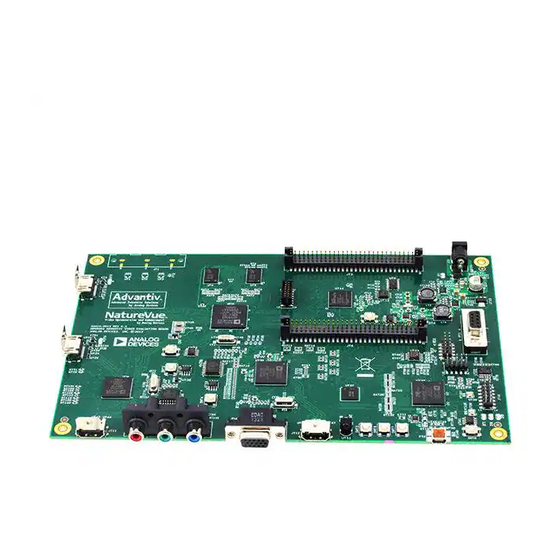
Video Signal Processor with Motion Adaptive Deinterlacing, Scaling, Bitmap OSD, Dual HDMI Tx and Video Encoder
Brand:
Analog Devices
| Category:
Signal Processors
| Size: 6 MB
Table of Contents
Table of Contents
2
Understanding the ADV8003 Hardware Manual
10
Description of the Hardware Manual
10
Disclaimer
10
Trademark and Service Mark Notice
10
Number Notations
10
Register Access Conventions
10
Acronyms and Abbreviations
10
Field Function Description
13
Figure 1: Field Description Format
13
References
14
1 Introduction to the ADV8003
15
Overview
15
Digital Video Input
16
Table 1: Available Features Within ADV8003 Family of Ics
16
Figure 2: ADV8003 Digital Video Interface
17
Figure 3: ADV8003 Video Processing
17
Flexible Digital Core
17
Video Signal Processor
17
Bitmap on Screen Display
18
Figure 4: ADV8003 Bitmap OSD
18
External DDR2 Memory
19
HDMI Transmitter
19
Video Encoder
19
Main Features of the ADV8003
19
Figure 5: External DDR2 Memory Interface
19
Primary VSP
19
Video Signal Processor
19
HDMI 1.4 Transmitter
20
Osd
20
Secondary VSP
20
Video Encoder
20
ADV8003 Functional Block Diagram
21
Figure 6: ADV8003 Block Diagram
21
ADV8003 Pinouts
22
Figure 7. ADV8003KBCZ-8 and ADV8003KBCZ-7 Pin Configuration
22
Figure 8. ADV8003KBCZ-8B and ADV8003KBCZ-7B Pin Configuration
34
Figure 9. ADV8003KBCZ-8C and ADV8003KBCZ-7C Pin Configuration
45
Figure 10. ADV8003KBCZ-7T Pin Configuration
56
Protocol for Main I C Port
67
Figure 11: Register Map Architecture
67
Table 6: ADV8003 I C Address and Register Address Range for Different HW Blocks
67
Configuring the ADV8003
68
Figure 12: Bus Data Transfer
68
Figure 13: Read and Write Sequence
68
2 ADV8003 Top Level Control
69
Figure 14: ADV8003 Simplified Block Diagram
69
ADV8003 Modes of Operation
70
Table 7: ADV8003 Modes of Operation
70
Mode 1
71
Selecting a Mode
71
Figure 15: ADV8003 Mode 1 Configuration
72
Figure 16: ADV8003 Mode 2 Configuration
73
Mode 2
73
Figure 17: ADV8003 Mode 3 Configuration
74
Mode 3
74
Figure 18: ADV8003 Mode 4 Configuration
75
Mode 4
75
Figure 19: ADV8003 Mode 5 Configuration
76
Mode 5
76
Figure 20: ADV8003 Mode 6 Configuration
77
Mode 6
77
Figure 21: ADV8003 Mode 7 Configuration
78
Mode 7
78
Figure 22: ADV8003 Mode 8 Configuration
79
Mode 8
79
Figure 23: ADV8003 Mode 9 Configuration
80
Mode 9 - Bypass
80
Figure 24: ADV8003 Mode 10 Configuration
81
Mode 10 - Picture in Picture (Pip) (External OSD Less than 720P)
81
Figure 25: ADV8003 Mode 11 Configuration
82
Mode 11 - PIP (External OSD Greater than or Equal to 720P)
82
Figure 26: ADV8003 Mode 12 Configuration
83
Mode 12 - Dual Zone OSD
83
Figure 27: ADV8003 Mode 13 Configuration
84
Mode 13 - OSD from HDMI RX
84
ADV8003 Top Level Overview
85
Figure 28: ADV8003 Mode 14 Configuration
85
Mode 14 - Handling Triple Inputs
85
Video Muxing
85
Figure 29: ADV8003 Digital Core Muxing
86
Figure 31: EXOSD TTL Input Channel
86
Figure 32: RX Input Channel
86
Digital Video Input
89
Figure 30: Video TTL Input Channel
89
EXOSD TTL Input
90
Video TTL Input
90
Figure 33: TTL Output Block Diagram
91
TTL Output
91
Primary Input Channel
93
Serial Video Rx
93
Figure 34: DDR Mode, Luma and Chroma Swap
94
Figure 35: Contrast Processing
98
Figure 36: Brightness Processing
99
Figure 37: Saturation Processing
100
Secondary Input Channel
100
Figure 38: DDR Mode, Luma and Chroma Swap
101
RX Input Channel
105
Clock Configuration
106
Figure 39: Updither Operation
106
Updither Configuration
106
Figure 40: Configuring Input Port Clock
107
Figure 41: PVSP/SVSP Output Clock Configure
110
Table 8: Example Values for Dpll_Clock_Period
110
PVSP Output Timing
111
SVSP Output Timing
111
Frame Tracking
112
DDR2 Configuration
113
DDR2 Interface
113
Table 9: Frame Tracking
113
DDR2 Bandwidth and Memory Selection
115
Figure 42: DDR2 PLL Architecture
115
Table 10: Indication of ADV8003 Capabilities with One DDR2 Memory
115
Table 11: Indication of ADV8003 Capabilities with Two DDR2 Memories
116
Table 12: Indication of ADV8003 Capabilities with Different Memory Sizes
116
DDR2 Loopback Test
117
Figure 43: DDR2 Loopback Test Architecture
117
Single DDR2 Memory Configuration
117
I 2 C Auto Increment
118
Extraction Overview
119
SPI Loop through
119
VBI Data Insertion
119
Ancillary Data Extraction
120
Figure 44: VBI Data Extraction Block Diagram
120
Table 13: Output Mode Outline
120
SPI Data Extraction
121
VBI Data Delay
121
Resets
122
AV-Codes
125
Figure 45: ADV8003 Image Processing Colorimetry Breakdown
125
Image Processing Colorimetry Breakdown
125
Color Space Conversion
130
Figure 46: 720(1440) X 240P @ 59.94/60Hz, CEA Formats 8 and 9
130
Figure 47: Primary Input Channel CSC
130
Primary Input Channel CSC
130
Secondary Input Channel CSC
133
Figure 48: Secondary Input Channel CSC
134
RX Input Channel CSC
136
Figure 49: RX Input Channel CSC
137
HDMI Transmitter Cscs
139
Figure 50: HDMI TX CSC
140
ADV8003 Silicon Revision
142
System Configuration
143
3 Video Signal Processing
144
Introduction
144
Primary VSP
144
Figure 51: ADV8003 PVSP
144
Introduction to PVSP
144
Autoconfiguration
146
Table 22: PVSP Supported Input Video Timing and VID
146
Table 23: PVSP Supported Output Video Timing and VID
147
Customized Input/Output Video Format Configuration
148
Field/Frame Buffer Address and Size
149
Field/Frame Buffer Number
149
Frame Latency
151
Table 24: Frame Latency in Normal Mode
151
Game Mode
153
Low Latency Mode
154
Table 25: Frame Latency in Low Latency Mode
154
Figure 52: 2:3 Frame Rate Conversion
155
Freezing Output Video
155
Progressive Cadence Detection
155
Figure 53: PVSP Video Input Module
156
Figure 54: VIM Crop Dimensions
156
PVSP Video Input Module
156
VIM Cropper
156
Horizontal down Scaler
158
Scaler Interpolation Mode
158
Pixel Packer
159
Scaler Controls
159
Figure 55: PVSP Video Output Module
160
PVSP Video Output Module
160
Table 26: Bytes Per Pixel
160
Pixel Unpacker
161
VOM Cropper
161
Figure 56: vom Crop Dimensions
162
Motion Detection
163
Cadence Detection
164
Low Angle De-Interlacing
164
Table 27: Corresponding Bit for each Cadence Type
165
CUE Correction
166
Random Noise Reduction
166
Mosquito Noise Reduction
167
Block Noise Reduction
168
Table 28: Corresponding Value for Block Noise Reduction Level
168
Scaler
170
Sharpness Enhancement
170
Figure 57: vom Scaler Dimensions
172
Figure 58: Panorama Scaling Feature
172
Panorama Mode
172
Output Port
173
Figure 59: vom Output Dimensions
176
Table 29: Output Port Configuration Settings for Example Output Resolutions
176
Demo Function
177
Progressive to Interlaced Converter
179
Automatic Contrast Enhancement
180
Secondary VSP
180
Figure 60: ADV8003 SVSP
180
Introduction to SVSP
180
Table 30: VID Set to Ptoi
180
Autoconfiguration
182
Table 31: SVSP Supported Input Video Timing and VID
182
Table 32: SVSP Supported Output Video Timing and VID
183
Customized Input/Output Video Format Configuration
184
Frame Buffer Address and Size
185
Frame Buffer Number
185
Frame Latency
187
Table 33: Frame Latency in Normal Mode
187
Figure 61: SVSP Video Input Module
189
Freezing Output Video
189
SVSP Video Input Module (VIM)
189
VIM Cropper
189
Figure 62: VIM Crop Dimensions
190
Scaler
191
Figure 63: VIM Scaler Dimensions
192
Scaler Interpolation Mode
192
VIM Miscellaneous Control
192
Panorama Mode
193
Figure 64: SVSP Video Output Module (VOM)
194
Pixel Packer
194
SVSP Video Output Module
194
Pixel Unpacker
195
VOM Cropper
195
Figure 65: vom Crop Dimensions
196
Output Port
197
Table 34: Output Port Configuration Settings for Example Output Formats
199
Figure 66: vom Output Dimensions
200
DDR Bypass Mode
201
Progressive to Interlaced Converter in SVSP
201
VSP Register Access Protocols
202
Bootup Protocol
202
Table 35: VID for Ptoi
202
Figure 67: Bootup Protocol Flowchart
203
Reboot Protocol
203
Figure 68: Reboot Protocol Flowchart
204
Figure 69: Gentle Reboot Protocol Flowchart
205
Gentle Reboot Protocol
205
Figure 70: vom Set Protocol Flowchart
206
Figure 71: Free Access Protocol
206
Free Access Protocol
206
VOM Set Protocol
206
Progressive to Interlaced Conversion
207
4 On Screen Display
208
Introduction
208
Features
208
OSD System Application Diagram
208
Typical OSD Component Sizes
209
Architecture Overview
209
Figure 72: Typical Application Diagram
209
Introduction
209
Table 36: Output Port Configuration Settings for Example Output Formats
209
Top Level Diagram
209
Figure 73: Bitmap OSD Top Level Diagram
210
OSD Blending
210
External Alpha Blending
211
Figure 74: OSD Scaler and Blending Top Level Diagram
211
OSD Core
211
Figure 75: Definition of OSD Region
212
OSD Core Region Definition
212
Table 37: Regions Used for OSD Components
212
Figure 76: OSD Menu Bar Component
213
OSD Color Space
213
OSD Timers
213
OSD Master/Slave SPI Interface
217
OSD Scaler
217
Figure 77: Data Loaded from SPI Flash through ADV8003 SPI Master Interface
218
Overview
218
Figure 78: MCU as SPI Master Sending OSD Data through ADV8003 SPI Slave Interface
219
Figure 79: SPI Loopback Enabled so MCU Can Program SPI Flash
220
Figure 80: SPI Slave Interface Timing and Data Format
223
SPI Slave Interface
223
Figure 81: SPI Master Interface Timing and Data Format
225
SPI Master Interface
225
OSD Initialization
226
5 Serial Video Receiver
227
Detect
227
Figure 82: Functional Block Diagram of ADV8003 Serial Video Rx
227
TMDS Clock Activity Detection
228
Clock and Data Termination Control
229
AV Mute Status
229
Deep Color Mode Support
229
Video FIFO
230
Figure 83: HDMI Video FIFO
231
Pixel Repetition
232
Sync Signal Polarity Readbacks
233
Figure 84: Horizontal Timing Parameters
234
Figure 85: Vertical Parameters for Field 0
234
Infoframe Registers
235
Infoframe Checksum Error Flags
235
Infoframe Collection Mode
235
AVI Infoframe Registers
236
Table 38: AVI Infoframe Registers
236
SPD Infoframe Registers
237
Table 39: SPD Infoframe Registers
237
MPEG Source Infoframe Registers
238
Table 40: MPEG Infoframe Registers
238
Table 41: VS Infoframe Registers
238
Vendor Specific Infoframe Registers
238
Packet Registers
239
ISRC Packet Registers
239
Table 42: ISRC1 Packet Registers
239
Table 43: ISRC2 Packet Registers
240
Gamut Metadata Packets
241
Table 44: Gamut Metadata Packet Registers
241
Customizing Packet/Infoframe Storage Registers
242
HDMI Section Reset Strategy
244
6 HDMI Transmitter
245
Figure 86: Functional Block Diagram of HDMI Tx Core
245
Table 45: HDMI Transmitter Memory Addresses
245
General Controls
246
Reset Strategy
247
Table 46: HDMI Tx Main Map Reset Strategy
247
Table 47: HDMI Tx CEC Map Reset Strategy
247
AV Mute
248
HDMI DVI Selection
248
Table 48: HDMI Tx Packet Map Reset Strategy
248
Source Product Description Infoframe
249
Table 49: SPD Infoframe Configuration Register
249
Spare Packets
250
Table 50: Spare Packet 0 Configuration Register
250
Table 51: Spare Packet 1 Configuration Register
251
EDID/HDCP Controller Status
252
General Status and Interrupts
252
System Monitoring
252
Table 52: HDMI Tx Interrupt Bits in HDMI Tx Main Map Register 0Xec96
252
Table 53: HDMI Tx Interrupt Bits in Main Map Register 0Xec97
252
Table 54: Status Bits in Main Map Register 0Xec42
252
EDID/HDCP Controller Error Codes
253
Input Format
253
Video Setup
253
Figure 87: Format of Video Data Input into HDMI Tx Core
254
Video Mode Detection
254
Pixel Repetition
255
AVI Infoframe
256
Video Related Packets and Infoframes
256
MPEG Infoframe
257
Table 55: AVI Infoframe Configuration Registers
257
Gamut Metadata
258
Table 56: MPEG Infoframe Configuration Registers
258
Figure 88: I C Write Timing if GMP Data
259
Table 57: Gamut Metadata Packet Configuration Registers
259
Audio Architecture
260
Audio Setup
260
Table 58: HDMI TX Supported Audio Input Modes from Audio Input Pins
260
Audio Configuration
261
Table 59: Valid Configuration for Audio_Mode[1:0]
262
Table 60: Audio Input Format Summary
262
I2S Audio
263
Figure 89: IEC60958 Sub Stream
268
Figure 90: AES3 Stream Format Input to ADV8003
269
Figure 91: Timing of Standard I2S Stream Input to ADV8003
269
Figure 92: Timing for Right-Justified I2S Stream Input to ADV8003
269
Figure 93: Timing for Left-Justified I2S Stream Input to ADV8003
269
Figure 94: Timing for I2S Stream in 32-Bit Mode
270
Figure 95: Timing for I2S Stream in Left or Right-Justified and 32-Bit Modes
270
SPDIF Audio
270
DSD Audio
271
HBR Audio
271
Table 61: Valid Configuration for Audioif_Sf[2:0] Address B8 (Main), Address 0X74[4:2]
271
N and CTS Parameters
272
CTS Parameter
273
Figure 96: Audio Clock Regeneration
273
N Parameter
273
Recommended N and Expected CTS Values
273
Table 62: Recommended N and Expected CTS Values for 32 Khz Audio
274
Audio Sample Packets
275
Table 63: Recommended N and Expected CTS Values for 44.1 Khz and Multiples
275
Table 64: Recommended N and Expected CTS Values for 48 Khz and Multiples
275
Table 65: I S Channel Status ADV8003 Register Map Location of Fixed Value
278
Figure 97: Definition of Channel Status Bits 20 to 23
279
ACP Packet
280
Audio Infoframe
280
Table 66: Audio Infoframe Configuration Registers
280
ISRC Packet
281
Table 67: ACP Packet Configuration Registers
281
Table 68: ISRC1 Packet Configuration Registers
282
Table 69: ISRC2 Packet Configuration Registers
282
EDID Definitions
283
EDID Handling
283
Reading the EDID
283
Additional Segments
284
Figure 98: Reading Sink EDID through ADV8003
284
EDID Reread Control
285
Edid_Tries Control
285
HDCP Handling
285
One Sink and no Upstream Devices
285
Multiple Sinks and no Upstream Devices
286
Table 70: KSV Fields Accessed from EDID Map
287
Software Implementation
288
Figure 99: HDCP Software Implementation
289
Audio Return Channel
290
AV Mute
290
Charge Injection Settings
291
Table 71: Charge Injection Settings
291
7 Consumer Electronics Control
293
Figure 100: CEC Module Block Diagram
293
CEC Transmit Section
294
Main Controls
294
Table 72: CEC Outgoing Message Buffer Registers
294
CEC Receive Section
296
Logical Address Configuration
296
Receive Buffers
297
Table 73: CEC Incoming Frame Buffer 0 Registers
299
Table 74: CEC Incoming Frame Buffer 1 Registers
299
CEC Message Reception Overview
300
Table 75: CEC Incoming Frame Buffer 2 Registers
300
Antiglitch Filter Module
301
Figure 101: CEC Module Initialization
302
Initializing CEC Module
302
Typical Operation Flow
302
Using CEC Module as Initiator
302
Figure 102: Using CEC Module as Initiator
303
Figure 103: Using CEC Module as Follower
304
Using CEC Module as Follower
304
Low Power CEC Message Monitoring
305
8 Video Encoder
307
Introduction
307
Input Configuration
307
Figure 104: ADV8003 Encoder Block Diagram
307
Figure 105: Simplified View of ADV8003 Encoder Block
308
Output Configuration
310
Table 76: Standards Directly Supported by ADV8003 Encoder Processor
310
Additional Design Features
312
Output Oversampling
312
SD VCR FF/RW Synchronization
313
Subcarrier Frequency Lock (SFL) Mode
313
Table 77: Output Oversampling Modes and Rates
313
SD Subcarrier Frequency Control
314
Vertical Blanking Interval
314
Filters
315
Programming the FSC
315
SD Filters
315
SD Noninterlaced Mode (240P/288P)
315
Table 78: Typical F
315
Table 79: Internal Filter Specifications
315
Figure 106: SD Luma SSAF Filter, Programmable Responses
316
Figure 107: SD Luma SSAF Filter, Programmable Gains
317
Figure 108: SD Luma SSAF Filter, Programmable Attenuation
317
ED/HD Filters
318
Figure 109: Prpb SSAF Filter
318
ED/HD Test Pattern Generator
319
Figure 110: ED/HD Sinc Compensation Filter Enabled
319
Figure 111: ED/HD Sinc Compensation Filter Disabled
319
Table 80: Sample Color Values for EIA 770.2/EIA770.3 ED/HD Output Standard Selection
320
Color Space Conversion Matrix
321
ED/HD Manual CSC Matrix Adjust Feature
321
Programming the CSC Matrix
322
SD Luma and Color Scale Control
322
Table 81: ED/HD Manual CSC Matrix Default Values
322
SD Hue Adjust Control
324
SD Brightness Control
325
SD Brightness Detect
325
Double Buffering
326
ED/HD Doubling Buffering
326
Figure 112: Examples of Brightness Control Values
326
SD Doubling Buffering
326
Table 82: Sample Brightness Control Values
326
Figure 113: Programmable DAC Gain - Positive and Negative Gain
327
Programmable DAC Gain Control
327
Table 83: DAC Gain Control
328
Gamma Correction
329
ED/HD Gamma Correction
330
Figure 114: Signal Input (Ramp) and Signal Output for Gamma 0.5
330
Figure 115: Signal Input (Ramp) and Selectable Output Curves
330
SD Gamma Correction
331
Table 84: ED/HD Gamma Curve a
331
Table 85: ED/HD Gamma Curve B
331
ED/HD Sharpness Filter and Adaptive Filter Controls
332
ED/HD Sharpness Filter Mode
332
Table 86: SD Gamma Curve a
332
Figure 116: ED/HD Sharpness and Adaptive Filter Control Block
333
ED/HD Adaptive Filters
334
ED/HD Adaptive Filter Modes
336
ED/HD Sharpness Filter and Adaptive Filter Application Examples
337
Figure 117: ED/ HD Sharpness Filter Control with Different Gain Settings for ED/HD Sharpness Filter Gain Values
337
Table 87: ED/HD Sharpness Control Settings for Figure 117
337
Table 88: Register Settings for Figure 119
337
Figure 118: Input Signal to ED/HD Adaptive Filter
338
Figure 119: Output Signal from ED/HD Adaptive Filter (Mode A)
338
Figure 120: Output Signal from ED/HD Adaptive Filter (Mode B)
338
Figure 121: SD DNR Block Diagram
339
SD Digital Noise Reduction
339
Coring Gain Border
340
Coring Gain Data
340
Figure 122: SD DNR Offset Control
340
Border Area
341
DNR Threshold
341
Figure 123: SD DNR Border Area
341
Block Size Control
342
DNR Input Select Control
342
DNR Mode Control
342
Figure 124: SD DNR Input Filter Select
342
DNR Block Offset Control
343
Figure 125: Example of Active Video Edge Functionality
343
SD Active Video Edge Control
343
Figure 126: Example of Video Output with SD Active Video Edge Control Disabled
344
Figure 127: Example of Video Output with SD Active Video Edge Control Enabled
344
Vertical Blanking Interval
345
DAC Configurations
346
Figure 128: Example of Output Filter for SD, 16× Oversampling
346
Table 89: Output Filter Requirements
346
Video Output Buffer and Optional Output Filter
346
Voltage Reference
346
Figure 129: Example of Output Filter for ED, 8× Oversampling
347
Figure 130: Example of Output Filter for HD, 4× Oversampling
347
Figure 131: Output Filter Plot for SD, 16× Oversampling
347
Figure 132: Output Filter Plot for ED, 8× Oversampling
347
Figure 133: Output Filter Plot for HD, 4× Oversampling
348
9 Interrupts
349
Interrupt Pins
349
Interrupt Duration
349
Storing Masked Interrupts
350
Serial Video Rx Interrupts
350
Introduction
350
Figure 134: Level and Edge-Sensitive Raw, Status and Interrupt Generation
351
Figure 135: AVI_INFO_RAW and AVI_INFO_ST Timing
352
Figure 136: NEW_AVI_INFO_RAW and NEW_AVI_INFO_ST Timing
352
Interrupt Architecture Overview
354
Table 90: Serial Video Rx Level Sensitive Interrupts
354
Table 91: Serial Video Rx Edge Sensitive Interrupts
354
Multiple Interrupt Events
355
Serial Video Interrupts Validity Checking Process
355
VSP and OSD Section
355
Interrupt Architecture Overview
355
Table 92: VSP and OSD Interrupts
355
HDMI Tx Core
356
Interrupt Architecture Overview
356
Introduction
356
Table 93: HDMI Tx Interrupts
356
HDMI Tx Interrupt Polarity
357
PCB Layout Recommendations
358
Analogue/Digital Video Interface Outputs
358
External DDR2 Memory Requirements
358
Appendix A
358
Power Supply Bypassing
359
Figure 137: Recommended Power Supply Decoupling
359
General Digital Inputs and Outputs
360
XTAL and Load Cap Value Selection
360
Figure 138: Crystal Circuit
360
Table 94: Recommended PSU Decoupling for ADV8003-8 Parts
360
Encoder Component Placement
361
HDMI Transmitter Component Placement
361
Power Supply Design and Sequencing
361
Figure 139: Power Supply Design
362
Figure 140: Power Supply Sequence
362
ADV8003 Evaluation Board Schematics
363
Figure 141: ADV8003 Schematic
363
Appendix B
363
Figure 142: ADV8003 Schematic
364
Figure 143: ADV8003 Schematic
365
Figure 144: ADV8003 Schematic
366
Figure 145: ADV8003 Schematic
367
Figure 146: ADV8003 Schematic
368
Figure 147: ADV8003 Schematic
369
Figure 148: ADV8003 Schematic
370
Figure 149: ADV8003 Schematic
371
Figure 150: ADV8003 Schematic
372
Figure 151: ADV8003 Schematic
373
Figure 152: ADV8003 Schematic
374
Figure 153: ADV8003 Schematic
375
Figure 154: ADV8003 Schematic
376
Figure 155: ADV8003 Schematic
377
Figure 156: ADV8003 Schematic
378
Figure 157: ADV8003 Schematic
379
Figure 158: ADV8003 Schematic
380
Figure 159: ADV8003 Schematic
381
Figure 160: ADV8003 Schematic
382
Figure 161: ADV8003 Schematic
383
Figure 162: ADV8003 Schematic
384
Figure 163: ADV8003 Schematic
385
Figure 164: ADV8003 Schematic
386
Figure 165: ADV8003 Schematic
387
Figure 166: ADV8003 Schematic
388
Figure 167: ADV8003 Schematic
389
Figure 168: ADV8003 Schematic
390
Figure 169: ADV8003 Schematic
391
Figure 170: ADV8003 Schematic
392
Figure 171: ADV8003 Schematic
393
Appendix C ADV8003 Evaluation Board Layout
394
Figure 172: ADV8003 Layout
394
Figure 173: ADV8003 Layout
395
Figure 174: ADV8003 Layout
396
Figure 175: ADV8003 Layout
397
Figure 176: ADV8003 Layout
398
Figure 177: ADV8003 Layout
399
Figure 178: ADV8003 Layout
400
Figure 179: ADV8003 Layout
401
Package Outline Drawing
402
Appendix D
402
Unused Pin List
403
Appendix E
403
Pixel Input and Output Formats
416
Table 95: RGB Input Formats
416
Appendix F
416
Table 96: Ycbcr Input Formats
418
Table 97: Alpha Blending Input Formats
422
Table 98: RGB TTL Output Formats
425
Table 99: Ycrcb TTL Output Formats
428
List of Figures
431
List of Tables
435
List of Equations
437
Revision History
438
Advertisement
Advertisement
Related Products
Analog Devices ADV8005
Analog Devices ADV7604
Analog Devices ADV7619
Analog Devices ADV7511W
Analog Devices ADV7850
Analog Devices ADV7281-M
Analog Devices ADV7181B
Analog Devices ADV3222-EVALZ
Analog Devices ADV3222
Analog Devices ADV7610
Analog Devices Categories
Motherboard
Computer Hardware
Controller
Media Converter
Extender
More Analog Devices Manuals
Login
Sign In
OR
Sign in with Facebook
Sign in with Google
Upload manual
Upload from disk
Upload from URL