Sign In
Upload
Manuals
Brands
Agilent Technologies Manuals
Portable Generator
E8241A
Agilent Technologies E8241A Manuals
Manuals and User Guides for Agilent Technologies E8241A. We have
3
Agilent Technologies E8241A manuals available for free PDF download: User Manual, Service Manual, Installation Notes
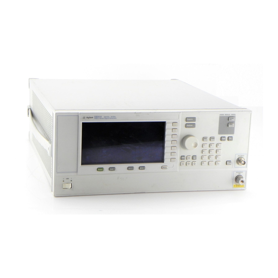
Agilent Technologies E8241A User Manual (281 pages)
PSG series Signal Generators
Brand:
Agilent Technologies
| Category:
Portable Generator
| Size: 1.87 MB
Table of Contents
Table of Contents
4
Signal Generator Overview
18
Signal Generator Models and Features
19
PSG-L Series Features
19
PSG-A Series Features
20
Options
21
Front Panel
22
Display
23
Softkeys
23
Knob
23
Amplitude Key
23
Frequency Key
23
Save Key
23
Recall Key
24
Trigger Key
24
Menu Keys
24
Help Key
24
EXT 1 INPUT (PSG-A Only)
24
EXT 2 INPUT (PSG-A Only)
25
LF OUTPUT (PSG-A Only)
25
Mod On/Off Key (PSG-A Only)
25
Alc Input
25
RF On/Off Key
25
Numeric Keypad
25
Rf Output
26
PULSE SYNC out (PSG-A Only)
26
PULSE VIDEO out (PSG-A Only)
26
Line Power LED
26
Power Switch
26
Standby LED
26
Incr Set Key
26
PULSE/TRIGGER GATE INPUT (PSG-A Only)
27
Arrow Keys
27
Hold Key
27
Return Key
27
Display Contrast Decrease Key
27
Display Contrast Increase Key
27
Local Key
27
Preset Key
27
Front Panel Display
28
Active Entry Area
29
Frequency Area
29
Annunciators
29
Amplitude Area
31
Error Message Area
31
Text Area
31
Softkey Label Area
31
Rear Panel
32
AC Power Receptacle
32
Gpib
32
Auxiliary Interface
33
Mhz in
33
Lan
33
Mhz out
33
Sweep out
33
Source Module
33
Trigger out
34
Trigger in
34
Source Settled Output
34
Fundamental Operation
36
Configuring the RF Output
37
Configuring a Continuous Wave RF Output
37
Configuring a Swept RF Output
41
Using the Signal Generator with a MM-Wave Source Module
46
Configuring Analog Modulation (PSG-A Series Only)
50
AM, FM, and ΦM Sources
50
Pulse Sources
51
Configuring am
52
Configuring FM
54
Configuring ΦM
55
Configuring Pulse Modulation
57
Configuring the LF Output (PSG-A Series Only)
58
Configuring the LF Output with an Internal Modulation Source
59
Configuring the LF Output with a Function Generator Source
60
Using Data Storage Functions
61
Using the Memory Catalog
61
Using the Instrument State Register
63
Using Table Editors
66
Modifying Items in the Table Editor
67
Table Editor Softkeys
67
Configuring for Remote Control
68
Configuring for a GPIB Interface
68
Configuring for a LAN (10BASE-T) Interface
68
Configuring for an RS-232 Interface
69
Optimizing Performance
70
Using External Leveling
71
Leveling with Detectors and Couplers/Splitters
71
Leveling with a Millimeter-Wave Source Module
75
Creating and Applying User Flatness Correction
76
Creating a User Flatness Correction Array
76
Creating a User Flatness Correction Array Using a MM-Wave Source Module
83
ALC Bandwidth Selection
91
Solving Problems
92
If You Encounter a Problem
93
Can't Turn off Help Mode
93
No RF Output
93
No Modulation at the RF Output
93
RF Output Power too Low
94
Signal Loss Occurs While Working with Mixers
95
Signal Loss Occurs While Working with Spectrum Analyzers
97
Sweep Appears to be Stalled
99
Cannot Turn off Sweep Mode
99
Incorrect List Sweep Dwell Time
100
Recalled a Register and Sweep List Is Missing
100
All of the Registers Where You Previously Stored Instrument States Are Empty
101
Wrong State
101
The Power Supply Has Shut down
101
Signal Generator Is Locked up
102
Upgrading Firmware
104
Returning a Signal Generator to Agilent Technologies
105
Key Reference
108
Symbols
109
Points
109
ΦM Dev
109
ΦM Dev Couple
110
ΦM off on
110
ΦM Path 1 2
111
ΦM Rate
111
ΦM Source
112
ΦM Start Rate
112
ΦM Stop Rate
113
ΦM Sweep Rate
113
ΦM Sweep Trigger
114
ΦM Tone 1 Rate
114
ΦM Tone 2 Ampl Percent of Peak
115
ΦM Tone 2 Rate
115
ΦM Waveform
116
Numerics
117
Khz
117
100 Hz
117
100 Khz
118
125 Hz
118
55 Hz
119
650 Hz
121
Abort
123
Abort Cal
123
Add Comment to Seq[N] Reg[Nn]
123
Adjust Phase
124
Alc Bw
124
ALC off on
125
All
125
AM Depth
126
AM Depth Couple off on
126
AM Mode Normal Deep
126
AM off on
127
AM Path 1 2
127
AM Rate
128
AM Source
128
AM Start Rate
129
AM Stop Rate
129
AM Sweep Rate
129
AM Sweep Trigger
130
AM Tone 1 Rate
130
AM Tone 2 Ampl Percent of Peak
130
AM Tone 2 Rate
131
AM Type Lin Exp
131
AM Waveform
131
Ampl
132
Ampl Offset
132
Ampl Ref off on
133
Ampl Ref Set
133
Ampl Start
134
Ampl Stop
134
Amplitude
135
Atten/Alc Control
135
Atten Hold off on
136
Auto
136
Binary
137
Black Pixels Screen Test
137
Brightness
137
Bus
138
Catalog Type
139
Clear Error Queue(S)
139
Clear Text
140
Configure Cal Array
140
Configure List Sweep
141
Configure Step Array
141
Configure Step Sweep
142
Confirm Delete
142
Confirm Delete of All Files
142
Confirm Load from Step Sweep
143
Confirm Preset
143
Copy File
143
DCFM/DCΦM Cal
144
Delete All Binary Files
145
Delete All <Catalog Type> Files
145
Delete All Files
146
Delete All List Files
146
Delete All Regs in Seq [N]
146
Delete All Sequences
147
Delete All State Files
147
Delete All UFLT Files
147
Delete File
148
Delete Item
148
Delete Row
148
Delete Seq[N] Reg[Nn]
149
Diagnostic Info
149
Display
150
Do Cal
151
Done
151
Do Power Search
151
Dual-Sine
152
Dwell Type List Step
152
E4416A
153
E4417A
153
E4418B
153
E4419B
154
Edit Comment in Seq[N] Reg[Nn]
154
Edit Item
154
Editing Keys
155
Editing Mode Insert Replace
155
Error Info
155
Ext
156
Ext Coupling DC AC
156
Ext Detector
157
Ext Detector Coupling Factor
157
Ext Impedance 50 Ohm 600 Ohm
157
Ext Polarity Normal Inverted
158
Ext Pulse
158
Ext1
158
Ext2
159
External Ref Bandwidth
159
Flatness off on
160
Fm/ΦM
160
FM ΦM Normal High BW
161
FM Dev
162
FM Dev Couple off on
163
FM off on
163
FM Path 1 2
164
FM Rate
164
FM Source
165
FM Start Rate
165
FM Stop Rate
166
FM Sweep Rate
166
FM Sweep Trigger
166
FM Tone 1 Rate
167
FM Tone 2 Ampl Percent of Peak
167
FM Tone 2 Rate
167
FM Waveform
168
Free Run
168
Freq
169
Freq Multiplier
169
Freq Offset
170
Freq Ref off on
170
Freq Ref Set
171
Freq Start
171
Freq Stop
171
Freq & Ampl
172
Frequency
172
Function Generator 1
172
Function Generator 2
173
Gaussian
174
Goto Bottom Row
174
Goto Middle Row
174
Goto Row
175
Goto Top Row
175
GPIB Address
175
Gpib/Rs-232 Lan
176
GPIB Listener Mode
176
Help
177
Help Mode Single Cont
177
Hold
178
Hostname
178
Incr Set
179
Insert Item
179
Insert Row
179
Installed Board Info
180
Instrument Adjustments
181
Instrument Info/Help Mode
181
Int Doublet
182
Int Free-Run
182
Int Gated
183
Int Triggered
184
Internal
184
Internal 1
185
Internal 2
185
Internal Monitor 1
185
Internal Monitor 2
186
Internal Ref Bandwidth
186
Internal Square
186
Inverse Video off on
187
IP Address
187
Keep Previous Comment
188
LAN Setup
189
Leveling Mode
189
LF out
189
LF out Amplitude into 50 Ohms
190
LF out Freq
190
LF out off on
190
LF out Source
191
LF out Start Freq
192
LF out Stop Freq
192
LF out Sweep Rate
193
LF out Sweep Trigger
193
LF out Tone 1 Freq
194
LF out Tone 2 Ampl % of Peak
194
LF out Tone 2 Freq
195
LF out Waveform
195
List
196
Load Cal Array from Step Array
196
Load from Selected File
196
Load List from Step Sweep
197
Load/Store
197
Local
197
Loop Selected Tests
198
Manual Mode off on
199
Manual Point
199
Meter Address
200
Meter Channel a B
200
Meter Timeout
200
Memory Catalog
201
Mod On/Off
201
Mod Status Info off on
202
Negative
203
Noise
203
Numeric Keypad
204
Off
205
Options Info
206
Page down
207
Phase Ref Set
207
Point Trigger
208
Positive
208
Power Meter
208
Power on Last Preset
209
Power On/Preset
209
Power Search
210
Power Search Manual Auto
210
Preset
210
Preset List
211
Preset Normal User
211
Pulse
211
Pulse Delay
212
Pulse off on
212
Pulse Period
213
Pulse Rate
213
Pulse Source
214
Pulse Width
214
Ramp
215
Recall
215
Recall Ref Osc Setting
216
Recall Reg
216
Ref Osc Coarse
216
Ref Osc Fine
217
Ref Oscillator Source Auto off on
217
Reference Oscillator Adjustment
217
Rename File
218
Re-SAVE Seq[N] Reg [N]
218
Reset RS-232
218
Restore Factory Defaults
219
Return
219
RF On/Off
219
Baud Rate
220
Echo off on
220
Setup
220
Timeout
221
Run Complete Self Test
221
Run Highlighted Tests
221
Run Selected Tests
222
Save
223
Save Reg
223
Save Seq[N] Reg[Nn]
224
Save User Preset
224
Screen Saver Delay
225
Screen Saver Mode
225
Screen Saver off on
226
Select/Deselect All
226
Select/Deselect Test
226
Select Reg
227
Select Seq
228
Self Test
228
Set ALC Level
228
Set Atten
229
Sine
229
Single Sweep
229
Source Module
230
Source Module off on
230
Square
230
State
231
Step Dwell
231
Step/Knob Ratio
232
Store to File
232
Store Ref Osc Setting
233
Sweep
233
Sweep Direction down up
233
Sweep Repeat Single Cont
234
Sweep Trigger
234
Sweep Type List Step
235
Sweep/List
235
Swept-Sine
236
Trans/Recv Pace None Xon
237
Triangle
237
Trigger
238
Trigger Key
238
Trigger in Polarity Neg Pos
239
Trigger out Polarity Neg Pos
239
Uniform
240
Utility
240
Update in Remote off on
241
User Flatness
241
View Details
242
View Next Error Message
242
View Previous Error Message
243
View Test Info
243
White Pixels Screen Test
244
Menu Maps
246
Amplitude
249
Fm/ΦM
252
Fm/ΦM
254
Frequency
256
LF Output
257
Pulse Modulation
259
Recall
260
Save
261
Sweep/List
262
Utility
264
Advertisement
Agilent Technologies E8241A Service Manual (251 pages)
Signal Generator
Brand:
Agilent Technologies
| Category:
Laboratory Equipment
| Size: 10.63 MB
Table of Contents
Table of Contents
4
Troubleshooting
14
Before Troubleshooting
15
ESD Information
15
Getting Started with Troubleshooting
16
To Run Self-Test
16
ILT-1 Power Supply Failure and Self-Test
17
ILT-2 Temperature Related Power Supply Failure
18
ILT-3 A18 CPU Turn-On Test
19
ILT4 Front Panel Display Troubleshooting
22
Symptom: Dark Display
22
Symptom: Bright Display Without Characters
23
Symptom: Hardkeys or Softkeys Not Functioning
25
Symptom: RPG Knob Not Functioning
27
Symptom: Screen Saver Not Functioning
27
Self-Test Failures and Related Troubleshooting
28
Troubleshooting Assembly Level Problems
30
Power Supplies
30
Self-Tests 2Xx: A5 Sampler Self-Test Errors
37
Self-Tests 3Xx: A7 Reference (Standard) Self-Test Errors
39
Self-Tests 4Xx: A8 Output Self-Test Errors
40
Self-Tests 6Xx: A9 YIG Driver Self-Test Errors
42
Self-Tests 7Xx: A6 Frac-N Self-Test Errors
44
Self-Tests 9Xx: A10 ALC Self-Test Errors
47
Self-Tests 10Xx: A7 Reference (Option UNJ) Self-Test Errors
49
Self-Tests 11Xx: A18 CPU Self-Test Errors
51
Self-Tests 12Xx: A26 MID Self-Test Errors
53
Self-Tests 13Xx: A11 Analog/Pulse Modulation Generator Self-Test Errors
56
Troubleshooting Unlocks
59
508 A6 Frac-N Loop Unlock
59
513 1 Ghz out of Lock
59
514 Reference Oven Cold
59
515 10 Mhz Signal Bad
59
520 Sampler Unlocked
60
521 YO Loop Unlocked
60
625 Internal Pulse Generator Unlock
60
626 Internal Mod Source Unlock
61
Troubleshooting Unlevels
62
Troubleshoot and Correct any Unlock Problems before Troubleshooting Unleveled Problems
62
Troubleshooting Adjustment Problems
66
Troubleshooting ADC Adjustment Failures
68
Troubleshooting Performance Test Problems
69
Troubleshooting the RF Path
71
ALC and RF Problems
71
Troubleshooting Pulse Modulation
72
Troubleshooting Problems <3.2 Ghz
72
Troubleshooting AT1 Attenuator
74
Troubleshooting Harmonic Spurious
75
20 Ghz Models
75
40 Ghz Models Only
76
Troubleshooting Non-Harmonic Spurious
78
Troubleshooting Option UNJ Phase Noise
79
Overall Block Diagram
81
Overall Block Description
82
A19 Power Supply
82
A18 Cpu
82
Input/Output Interface
82
Frequency Generation
83
Reference/Synthesis Loop Block Diagram
87
Reference/Synthesis Loop Block Description
88
A7 Reference
88
A5 Sampler
88
A6 Frac-N
89
A9 YIG Driver
89
A28 YIG Oscillator (YO)
89
A29 20 Ghz Doubler
89
RF Path Block Diagram
91
RF Path Block Description (Frequency Generation, Level Control, and Modulation)
92
Frequency Generation
92
A29 20 Ghz Doubler
92
A6 Frac-N
92
A8 Output
92
A30 Modulation Filter
93
A27 40 Ghz Doubler
93
A23 Low Band Coupler/Detector, A24 High Band Coupler, and A25 High Band Detector
93
ALC Loop
93
A10 Alc
93
Modulation (AM, FM, PM, and Pulse)
94
Self-Test Overview
95
Contacting Agilent Technologies
97
Review the Warranty
97
Contacting Agilent Sales and Service Offices
98
Important Information Needed by an Agilent Service Representative
98
Returning Your Signal Generator for Service
99
Assembly Replacement
100
Before You Replace an Assembly
101
After Replacing or Repairing an Assembly
101
Assemblies that You Can Replace
102
Outer Instrument Cover
103
Tools Required
103
Removal Procedure
103
Replacement Procedure
103
Inner Instrument Cover
105
Tools Required
105
Removal Procedure
105
Replacement Procedure
105
Front Panel
107
Tools Required
107
Removal Procedure
107
Replacement Procedure
108
A1 Keyboard
109
Tools Required
109
Removal Procedure
109
Replacement Procedure
109
A2 Display
111
Tools Required
111
Removal Procedure
111
Replacement Procedure
111
A2DS1 Display Backlight
113
Tools Required
113
Removal Procedure
113
Replacement Procedure
113
A3 Power Switch
115
Tools Required
115
Removal Procedure
115
Replacement Procedure
115
A4 Inverter
117
Tools Required
117
Removal Procedure
117
Replacement Procedure
117
A5 Sampler
119
Tools Required
119
Removal Procedure
119
Replacement Procedure
119
A6 Frac-N
121
Tools Required
121
Removal Procedure
121
Replacement Procedure
121
A7 Reference (Standard and Option UNJ)
123
Tools Required
123
Removal Procedure
123
Replacement Procedure
123
A8 Output
125
Tools Required
125
Removal Procedure
125
Replacement Procedure
125
A9 YIG Driver
127
Tools Required
127
Removal Procedure
127
Replacement Procedure
127
A10 Alc
129
Tools Required
129
Removal Procedure
129
Replacement Procedure
129
A11 Pulse/Analog Modulation Generator
131
Tools Required
131
Removal Procedure
131
Replacement Procedure
131
A18 Cpu
133
Tools Required
133
Removal Procedure
133
Replacement Procedure
133
A18Bt1
135
Tools Required
135
Removal Procedure
135
Replacement Procedure
135
A19 Power Supply
137
Tools Required
137
Removal Procedure
137
Replacement Procedure
137
Rear Panel
139
Tools Required
139
Removal Procedure
139
Replacement Procedure
139
A20 SMI (Source Module Interface)
141
Tools Required
141
Removal Procedure
141
Replacement Procedure
141
A21 Rear-Panel Interface
143
Tools Required
143
Removal Procedure
143
Replacement Procedure
143
A22 Line Module
145
Tools Required
145
Removal Procedure
145
Replacement Procedure
145
AT1 115 Db Attenuator (Option 1E1)
147
Tools Required
147
Removal Procedure
147
Replacement Procedure
147
A23 Low Band Coupler/Detector
149
Tools Required
149
Removal Procedure
149
Replacement Procedure
149
A24 20 Ghz High Band Coupler (E8241A and E8251A Models Only)
151
Tools Required
151
Removal Procedure
151
Replacement Procedure
151
A24 40 Ghz High Band Coupler (E8244A and E8254A Models Only)
153
Tools Required
153
Removal Procedure
153
Replacement Procedure
153
A25 20 Ghz High Band Detector with A25B Detector Bias Board (E8241A and E8251A Models Only)
155
Tools Required
155
Removal Procedure
155
Replacement Procedure
155
A25 40 Ghz High Band Detector with A25B Detector Bias Board (E8244A and E8254A Models Only)
157
Tools Required
157
Removal Procedure
157
Replacement Procedure
157
A26 MID (Microcircuit Interface Deck)
159
Tools Required
159
Removal Procedure
159
Replacement Procedure
159
A27 40 Ghz Doubler (E8244A and E8254A Models Only)
161
Tools Required
161
Removal Procedure
161
Replacement Procedure
161
A28 YIG Oscillator
163
Tools Required
163
Removal Procedure
163
Replacement Procedure
163
A29 20 Ghz Doubler
165
Tools Required
165
Removal Procedure
165
Replacement Procedure
165
A30 Modulation Filter (Standard and Option 1EA)
167
Tools Required
167
Removal Procedure
167
Replacement Procedure
167
A31 Motherboard
169
Tools Required
169
Removal Procedure
169
Replacement Procedure
169
A32 10 Mhz Crystal Oscillator (Option UNJ)
171
Tools Required
171
Removal Procedure
171
Replacement Procedure
171
B1 Fan
173
Tools Required
173
Removal Procedure
173
Replacement Procedure
173
Replaceable Parts Ordering Information
177
Call (800) 227-8164 to Order Parts Fast (U.S. Only)
177
Save Money with Rebuilt-Exchange Assemblies
178
Shipping the Defective Assembly Back to Agilent Technologies
179
Abbreviations Used in Part Descriptions
180
Major Assemblies
181
Major Assemblies Top View
182
Major Assemblies Bottom View
183
Major Assemblies Microcircuit Deck View
184
Inside Front Panel View
185
A1 Keyboard
185
A2 Display
185
A2DS1 Backlight
185
A3 Power Switch
185
A4 Inverter
185
Main Chassis Top View
187
A5 Sampler
187
A6 Frac-N
187
A7 Reference (Standard)
187
A7 Reference (Option UNJ)
187
A8 Output
187
A9 YIG Driver
187
A10 Alc
187
A11 Pulse/Analog Modulation Generator (E8251A and E8254A Models Only)
187
A18 Cpu
187
Main Chassis Bottom View
189
Inside Rear Panel View
191
A20 SMI (Source Module Interface)
191
A21 Rear Panel Interface
191
A22 Line Module
191
Microcircuit Interface Deck Top View
192
AT1 115 Db Attenuator (Option 1E1)
192
A23 Low Band Coupler/Detector
192
A25B High Band Detector Bias Board
192
A26 MID (Microcircuit Interface Deck)
192
MID Bottom View
193
A28 YIG Oscillator
193
A29 20 Ghz Doubler
193
Battery-Lithium
195
Cables
196
Inside Front Panel View
197
Main Chassis Top View
199
Rear Panel View
201
MID Top View (E8244A and E8254A Models Only)
203
MID Top View (E8241A and E8251A Models Only)
205
MID Bottom View
207
Main Chassis Bottom View
209
Hardware and Other Instrument Parts
211
Front Panel View
212
Disassembled Front Panel View
213
Disassembled Rear Panel View
215
Disassembled A32 10 Mhz Crystal Oscillator (Option UNJ)
217
Disassembled AT1 115 Db Attenuator View (Option 1E1)
218
Disassembled A29 20 Ghz Coupler/Detector (E8241A and E8251A Models Only)
219
Disassembled A24 High Band Coupler and A25 High Band Detector (E8244A and E8254A Models Only)
220
Microcircuit Interface Deck Top View
221
Main Chassis and MID Bottom View
223
MM RF Output Connector (E8244A and E8254A Models Only)
225
APC 3.5 RF Output Connector (E8241A and E8251A Models Only)
226
Type-N RF Output Connector (E8241A and E8251A with Option 1ED Models Only)
227
Main Chassis with Inside Cover and Right-Side Support Wall
228
Outer and Inner Instrument Covers and Associated Parts
229
Miscellaneous
230
Accessories
231
Documentation
231
Electrostatic Discharge (ESD) Protective Supplies
231
Post-Repair Procedures
234
Post-Repair Procedures Matrix
235
Safety and Regulatory
240
General Safety Considerations
242
Lithium Battery Disposal
243
Warranty
244
Assistance
245
Notice
246
Certification
247
Agilent Technologies E8241A Installation Notes (12 pages)
Signal Generators Add Option 1E1 Attenuator Upgrade Kit
Brand:
Agilent Technologies
| Category:
Portable Generator
| Size: 0.45 MB
Table of Contents
Installation Kit Parts List
4
Safety Considerations
4
Tools Required
6
Removing the Outer Cover
6
Installation Procedure
9
Advertisement
Advertisement
Related Products
Agilent Technologies E8244A
Agilent Technologies E8254A
Agilent Technologies E8251A
Agilent Technologies E8251-60088
Agilent Technologies E8251-60417
Agilent Technologies E8251-60980
Agilent Technologies E8311A
Agilent Technologies E8312A
Agilent Technologies E8306A
Agilent Technologies ESG series
Agilent Technologies Categories
Measuring Instruments
Laboratory Equipment
Test Equipment
Water Pump
Power Supply
More Agilent Technologies Manuals
Login
Sign In
OR
Sign in with Facebook
Sign in with Google
Upload manual
Upload from disk
Upload from URL