
Related Manuals for Agilent Technologies E8241A


Summary of Contents for Agilent Technologies E8241A
- Page 1 Keysight/Agilent/HP E8244A Manual Get Pricing & Availability at ApexWaves.com Call Today: 1-800-915-6216 Email: sales@apexwaves.com https://www.apexwaves.com/signal-generators/keysight-technologies/e82xx-psg-signal-generators/E8244A...
- Page 2 This guide applies to the signal generator models and associated serial number prefixes listed below. Depending on your firmware revision, front panel operation may vary from descriptions in this guide. E8241A: US4124 E8244A: US4124 E8251A: US4124 E8254A: US4124 Part Number: E8251-90023 Printed in USA July 2001 © Copyright 2001 Agilent Technologies.
-
Page 4: Table Of Contents
Contents 1. Signal Generator Overview ......... .1 Signal Generator Models and Features . - Page 5 Contents Front Panel Display ............11 1.
- Page 6 Upgrading Firmware ........... . 87 Returning a Signal Generator to Agilent Technologies ......88...
- Page 7 Contents 5. Key Reference ........... . 91 Symbols.
- Page 8 Contents A ..............106 Abort .
- Page 9 Contents B ..............120 Binary .
- Page 10 Contents Done............. . . 134 Do Power Search .
- Page 11 Contents FM Tone 1 Rate ............150 FM Tone 2 Ampl Percent Of Peak .
- Page 12 Contents Instrument Info/Help Mode ..........164 Int Doublet .
- Page 13 Contents M ..............182 Manual Mode Off On .
- Page 14 Contents R ..............198 Ramp .
- Page 15 Contents Sine ............. . . 212 Single Sweep .
- Page 16 Contents 6. Menu Maps ........... . . 229 AM.
- Page 17 Contents...
-
Page 18: Signal Generator Overview
Signal Generator Overview... -
Page 19: Signal Generator Models And Features
PSG-L Series Features The PSG-L Series includes the following features: • CW output from 250 kHz to 20 GHz (E8241A) or 40 GHz (E8244A) • list and step sweep of frequency and amplitude, with multiple trigger sources • external diode detector leveling •... -
Page 20: Psg-A Series Features
Signal Generator Overview Signal Generator Models and Features PSG-A Series Features The PSG-A Series provides all the functionality of the PSG-L and adds the following features: • closed-loop AM • dc-synthesized FM to 10 MHz rates; deviation depends on the carrier frequency •... -
Page 21: Options
Signal Generator Overview Options Options Table 1-2 Table 1-3 show the available hardware and accessory options for both the PSG-A and PSG-L Series signal generators. Table 1-2 Signal Generator Hardware Options Option Description add output step attenuator add high RF output power add Type-N RF output connector (20 GHz models only) add improved close-in phase noise add 5-year warranty... -
Page 22: Front Panel
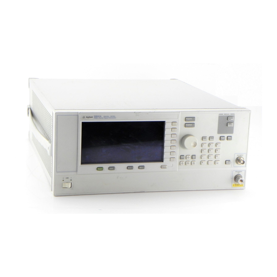
Signal Generator Overview Front Panel Front Panel Figure 1-1 shows the PSG-A signal generator front panel. This interface enables you to define, monitor, and manage input and output characteristics. Although Figure 1-1 shows the PSG-A Series front panel, descriptions are valid for both PSG Series. The PSG-L Series front panel has fewer connectors and menu hardkeys. -
Page 23: Display
Signal Generator Overview Front Panel 1. Display The LCD screen provides information on the current function. Information can include status indicators, frequency and amplitude settings, and error messages. Labels for the softkeys are located on the right-hand side of the display. For further description of the front panel display, refer to “Front Panel Display”... -
Page 24: Recall Key
Signal Generator Overview Front Panel 7. Recall Key This hardkey restores any instrument state that you previously saved in a memory register. 8. Trigger Key This hardkey initiates an immediate trigger event, for a function such as a list or step sweep. The trigger mode must be set to prior to initiating a trigger event with this Trigger Key... -
Page 25: Ext 2 Input (Psg-A Only)
Signal Generator Overview Front Panel 12. EXT 2 INPUT (PSG-A only) This BNC input connector accepts a ±1 V signal for AM, FM, ΦM, and pulse modulation. With AM, FM, or ΦM, ±1 V produces the indicated deviation or depth. With pulse modulation, +1 V is on and 0 V is off. -
Page 26: Rf Output
Signal Generator Overview Front Panel 18. RF OUTPUT This connector is the output for RF signals. The nominal output impedance is 50Ω. The damage levels are 0 Vdc, 0.5 watts nominal. 19. PULSE SYNC OUT (PSG-A only) This connector outputs a sychronizing TTL-compatible signal that is nominally 50 ns wide during internal and triggered pulse modulation. -
Page 27: Pulse/Trigger Gate Input (Psg-A Only)
Signal Generator Overview Front Panel 25. PULSE/TRIGGER GATE INPUT (PSG-A only) This connector accepts an externally supplied TTL-compatible signal for use as a pulse or trigger input. The damage levels are ±5 V and 10 V . The nominal input impedance is 50Ω. 26. -
Page 28: Front Panel Display
Signal Generator Overview Front Panel Display Front Panel Display Figure 1-2 shows the front panel display. The LCD screen will display data fields, annotations, key press results, softkey labels, error messages, and annunciators that represent various active functions of the signal generator. Descriptions are provided for each feature of this interface. -
Page 29: Active Entry Area
Signal Generator Overview Front Panel Display 1. Active Entry Area The current active function is shown in this area. For example, if frequency is the active function, the current frequency setting will be displayed here. If the current active function has an increment value associated with it, that value is also displayed. - Page 30 Signal Generator Overview Front Panel Display This annunciator is displayed as either EXT2 LO or EXT2 HI. This EXT2 LO/HI annunciator appears whenever the ac-coupled signal to the EXT 2 INPUT is less than 0.97 V or greater than 1.03 V This annunciator appears when an external frequency reference is applied.
-
Page 31: Amplitude Area
Signal Generator Overview Front Panel Display 4. Amplitude Area The current output power level setting is shown in this portion of the display. Indicators are also displayed in this area when amplitude offset is used, amplitude reference mode is turned on, external leveling mode is enabled, a source module is enabled, and when user flatness is enabled. -
Page 32: Rear Panel
Signal Generator Overview Rear Panel Rear Panel Figure 1-3 shows the signal generator rear panel. The signal generator rear panel provides input, output, and remote interface connections. Descriptions are provided for each characteristic of the rear panel. Figure 1-3 Rear Panel Diagram 1. -
Page 33: Auxiliary Interface
Signal Generator Overview Rear Panel 3. AUXILIARY INTERFACE This male DB-9 connector is an RS-232 serial port that can be used for controlling the signal generator remotely. 4. 10 MHz IN This BNC connector accepts an external timebase reference input signal level of greater than −3 dBm. -
Page 34: Trigger Out
Signal Generator Overview Rear Panel 9. TRIGGER OUT This BNC connector outputs a TTL signal that is high at the start of a dwell sequence or when waiting for a point trigger in manual sweep mode. The signal is low when the dwell is over, or when a point trigger is received. - Page 35 Signal Generator Overview Rear Panel Chapter 1...
-
Page 36: Fundamental Operation
Fundamental Operation... -
Page 37: Configuring The Rf Output
Fundamental Operation Configuring the RF Output Configuring the RF Output This section will show you how to create continuous wave and swept RF outputs. Configuring a Continuous Wave RF Output Using these procedures, you will learn how to set the following parameters: •... - Page 38 Fundamental Operation Configuring the RF Output 5. Press > > > Frequency Incr Set This changes the frequency increment value to 1 MHz. 6. Press the up arrow key. Each press of the up arrow key increases the frequency by the increment value last set with the hardkey.
- Page 39 Fundamental Operation Configuring the RF Output 6. Press the up arrow key. This increments the output frequency by 1 MHz. The frequency display changes to show 1 MHz (the frequency output by the hardware, 700 MHz + 1 MHz, minus the reference frequency, 700 MHz) and the output frequency changes to 701 MHz.
- Page 40 Fundamental Operation Configuring the RF Output Setting the Amplitude Reference and Amplitude Offset The following procedure sets the RF output power as an amplitude reference to which all other amplitude parameters are relative. The amplitude initially shown on the display will be 0 dB (the power output by the hardware minus the reference power).
-
Page 41: Configuring A Swept Rf Output
Fundamental Operation Configuring the RF Output Configuring a Swept RF Output The signal generator has two sweep types, step and list. NOTE List sweep data cannot be saved within an instrument state, but can be saved to the memory catalog. For instructions on saving list sweep data, see “Storing Files”... - Page 42 Fundamental Operation Configuring the RF Output List Sweep List sweep allows you to create a list of arbitrary frequency, amplitude, and dwell time values and sweep the RF output based on the entries in the List Mode Values table. Unlike a step sweep that contains linear ascending/descending frequency and amplitude values spaced at equal intervals throughout the sweep, list sweep frequencies and amplitudes can be entered at unequal intervals and nonlinear ascending/descending or random order.
- Page 43 Fundamental Operation Configuring the RF Output 9. Press > > # Points Enter This sets the number of sweep points to nine. 10. Press > > Step Dwell msec This sets the dwell time at each point to 500 milliseconds. 11.
- Page 44 Fundamental Operation Configuring the RF Output 3. Press Configure List Sweep This opens another menu displaying softkeys that you will use to create the sweep points. The display shows the current list data. (When no list has been previously created, the default list contains one point set to the signal generator’s maximum frequency, minimum amplitude, and a dwell time of 2 ms.) 4.
- Page 45 Fundamental Operation Configuring the RF Output 9. Highlight the frequency item for point 8, then press Insert Item Pressing shifts frequency values down one row, beginning at point 8. Note that Insert Item the original frequency values for both points 8 and 9 shift down one row, creating an entry for point 10 that contains only a frequency value (the power and dwell time items do not shift down).
-
Page 46: Using The Signal Generator With A Mm-Wave Source Module
Fundamental Operation Configuring the RF Output Using Sweep with the Step Attenuator (Option 1E1) The signal generator protects the step attenuator from overuse during swept operation by automatically switching to attenuator hold mode whenever you select an amplitude sweep softkeys). The ATTN HOLD annunciator appears on the display when this Ampl Freq &... - Page 47 Fundamental Operation Configuring the RF Output Connect the Equipment CAUTION To prevent damage to the signal generator, turn off the line power to the signal generator before connecting the source module interface cable to the rear panel SOURCE MODULE interface connector. 1.
- Page 48 Fundamental Operation Configuring the RF Output Figure 2-2 Using a Millimeter-Wave Source Module with an Option 1EA Signal Generator Configure the Signal Generator 1. Turn on the signal generator’s line power. Upon power-up, the signal generator automatically: • senses the mm-wave source module, •...
- Page 49 Fundamental Operation Configuring the RF Output 2. If the RF OFF annunciator is displayed, press RF On/Off Leveled power is now available at the output of the millimeter-wave source module. To obtain flatness-corrected power, refer to “Creating and Applying User Flatness Correction” on page Chapter 2...
-
Page 50: Configuring Analog Modulation (Psg-A Series Only)
Fundamental Operation Configuring Analog Modulation (PSG-A Series Only) Configuring Analog Modulation (PSG-A Series Only) PSG-A signal generators can modulate the RF carrier with four types of analog modulation: amplitude, frequency, phase, and pulse. AM, FM, and ΦM Sources • AM, FM, and ΦM have two source paths each. These multiple source paths are summed internally for composite modulation of the RF carrier. -
Page 51: Pulse Sources
Fundamental Operation Configuring Analog Modulation (PSG-A Series Only) Pulse Sources The following list summarizes the different sources available for pulse modulation. External Pulse modulates by following an external pulse signal connected to the signal generator’s PULSE/TRIGGER GATE INPUT connector. Internal Doublet produces two pulses at the RF OUTPUT connector for each trigger event at the TRIGGER IN connector. -
Page 52: Configuring Am
Fundamental Operation Configuring Analog Modulation (PSG-A Series Only) Configuring AM Using this procedure, you will learn how to create a multipath amplitude-modulated RF carrier with the following characteristics: • RF output frequency set to 15 GHz • RF output amplitude set to 0 dBm •... - Page 53 Fundamental Operation Configuring Analog Modulation (PSG-A Series Only) Creating a Multipath AM Configuration Use the following steps to configure a multipath AM configuration. AM Path 1 and AM Path 2 are summed internally for composite modulation. Either path can be switched to any one of the modulation sources (internal 1 or 2, external 1 or 2), but any given source can only be routed to one modulation type at a time.
-
Page 54: Configuring Fm
Fundamental Operation Configuring Analog Modulation (PSG-A Series Only) Configuring FM Using this procedure, you will learn how to create a frequency-modulated RF carrier with the following characteristics: • RF output frequency set to 12 GHz • RF output amplitude set to 0 dBm •... -
Page 55: Configuring Φm
Fundamental Operation Configuring Analog Modulation (PSG-A Series Only) Activating FM Follow these remaining steps to output the frequency-modulated signal. 1. Press FM Off On The FM annunciator is activated indicating that you have enabled frequency modulation. 2. Press RF On/Off The RF ON annuciator is activated, indicating that the signal is now available at the RF OUTPUT connector. - Page 56 Fundamental Operation Configuring Analog Modulation (PSG-A Series Only) ΦM Dev 3. Press > > pi rad This changes the ΦM deviation to 0.25 π radians. ΦM Rate 4. Press > > This sets the ΦM rate to 10 kHz. The signal generator is now configured to output a 0 dBm, phase-modulated carrier at 20 GHz with a 0.25 π...
-
Page 57: Configuring Pulse Modulation
Fundamental Operation Configuring Analog Modulation (PSG-A Series Only) Configuring Pulse Modulation Using the following procedure you will learn how to create a pulse-modulated RF carrier with the following characteristics: • RF output frequency set to 18 GHz • RF output amplitude set to 0 dBm •... -
Page 58: Configuring The Lf Output (Psg-A Series Only)
Fundamental Operation Configuring the LF Output (PSG-A Series Only) Configuring the LF Output (PSG-A Series Only) The PSG-A Series signal generator has a low frequency (LF) output. The LF output’s source can be switched between an internal modulation source (internal monitor 1 or 2) or an internal function generator (function generator 1 or 2). -
Page 59: Configuring The Lf Output With An Internal Modulation Source
Fundamental Operation Configuring the LF Output (PSG-A Series Only) Configuring the LF Output with an Internal Modulation Source In this example, the internal FM modulation is the LF output source. Configuring the Internal Modulation as the LF Output Source 1. Press Preset 2. -
Page 60: Configuring The Lf Output With A Function Generator Source
Fundamental Operation Configuring the LF Output (PSG-A Series Only) Configuring the LF Output with a Function Generator Source In this example, function generator 1 is the LF output source. Configuring the Function Generator as the LF Output Source 1. Press Preset 2. -
Page 61: Using Data Storage Functions
Fundamental Operation Using Data Storage Functions Using Data Storage Functions This section explains how to use the two forms of signal generator data storage: the memory catalog and the instrument state register. Using the Memory Catalog The signal generator’s interface for stored files is the memory catalog. From there, you can view, copy, rename and delete files, either from the signal generator’s front panel or via remote controller. - Page 62 Fundamental Operation Using Data Storage Functions Storing Files To store a file to the memory catalog, first create a file. For this example, use the default list sweep table. 1. Press Preset 2. Press > > > Sweep/List Configure List Sweep More (1 of 2) Load/Store This opens the Catalog of List Files.
-
Page 63: Using The Instrument State Register
Fundamental Operation Using Data Storage Functions Deleting Stored Files 1. Highlight the desired file. 2. Press Delete File softkey appears. Confirm Delete 3. Press Confirm Delete Using the Instrument State Register The instrument state register is a section of memory divided into 10 sequences (numbered 0 through 9) each containing 100 registers (numbered 00 through 99). - Page 64 Fundamental Operation Using Data Storage Functions 4. Press Select Reg The register number in sequence 1 becomes the active function. The signal generator displays either the last register used, accompanied by the text: (in use), or (if no registers are in use) register 00, accompanied by the text: (available). Use the arrow keys to select register 01.
- Page 65 Fundamental Operation Using Data Storage Functions To Delete a Specific Register within a Sequence 1. Press Preset 2. Press the hardkey. Recall Save Notice that the softkey shows the last sequence that you used. Select Seq 3. Press and enter the sequence number containing the register you want to delete. Select Seq 4.
-
Page 66: Using Table Editors
Fundamental Operation Using Table Editors Using Table Editors The PSG signal generator uses table editors to simplify configuration tasks such as creating a list sweep. Using the List Mode Values table editor, the following section familiarizes you with basic table editor functionality. -
Page 67: Modifying Items In The Table Editor
Fundamental Operation Using Table Editors Table Editor Softkeys The following table editor softkeys are used to load, navigate, modify, and store table item values. Press to view additional table editor softkeys. More (1 of 2) displays the selected item in the active function area of the display where Edit Item the item’s value can be modified inserts an identical row of table items above the currently selected row... -
Page 68: Configuring For Remote Control
Fundamental Operation Configuring for Remote Control Configuring for Remote Control This section will show you how to configure the signal generator to interface with a remote controller. For more information refer to the programming guide. Front panel keys are locked when using a remote controller. Only the NOTE Local is active. -
Page 69: Configuring For An Rs-232 Interface
Fundamental Operation Configuring for Remote Control Configuring for an RS-232 Interface 1. Press > > Utility GPIB/RS-232 LAN RS-232 Setup 2. Press RS-232 Baud Rate Press the desired baud rate softkey to set the baud rate. 3. Press RS-232 Echo Off On This toggles the state of the SCPI echoing on the RS-232 connection. -
Page 70: Optimizing Performance
Optimizing Performance... -
Page 71: Using External Leveling
Optimizing Performance Using External Leveling Using External Leveling The PSG signal generator can be externally leveled by connecting an external sensor at the point where leveled RF output power is desired. This sensor detects changes in RF output power and returns a compensating voltage to the signal generator’s ALC input. The ALC circuitry raises or lowers (levels) the RF output power based on the voltage received from the external sensor, ensuring constant power at the point of detection. - Page 72 Optimizing Performance Using External Leveling Figure 3-1 External Detector Leveling with a Directional Coupler Configure the Signal Generator 1. Press Preset 2. Press > > Frequency 3. Press > > Amplitude 4. Press RF On/Off 5. Press > Leveling Mode External Detector This deactivates the internal ALC detector and switches the ALC input path to the front panel ALC INPUT connector.
- Page 73 Optimizing Performance Using External Leveling 7. Press > > (or the positive representation of the More (1 of 2) Ext Detector Coupling Factor value listed at the detector port of the directional coupler) > Leveled output power is now available at the output of the directional coupler. While operating in external leveling mode, the signal generator’s displayed RF NOTE output amplitude is affected by the coupling factor value, resulting in a...
- Page 74 Optimizing Performance Using External Leveling Figure 3-2 Typical Diode Detector Response at 25° C Chapter 3...
-
Page 75: Leveling With A Millimeter-Wave Source Module
Optimizing Performance Using External Leveling External Leveling with Option 1E1 Signal Generators Signal generators with Option 1E1 contain a step attenuator prior to the RF output connector. During external leveling, the signal generator automatically holds the present attenuator setting (to avoid power transients that may occur during attenuator switching) as the RF amplitude is changed. -
Page 76: Creating And Applying User Flatness Correction
Optimizing Performance Creating and Applying User Flatness Correction Creating and Applying User Flatness Correction User flatness correction allows the digital adjustment of RF output amplitude for up to 1601 frequency points in any frequency or sweep mode. Using an Agilent E4416A/17A or E4418B/19B power meter (controlled by the signal generator through GPIB) to calibrate the measurement system, a table of power level corrections is created for frequencies where power level variations or losses occur. - Page 77 Optimizing Performance Creating and Applying User Flatness Correction Required Equipment • Agilent E4416A/17A/18B/19B power meter • Agilent E4413A E Series CW power sensor • GPIB interface cable • adapters and cables, as required NOTE If the setup has an external leveling configuration, the equipment setup in Figure 3-3 assumes that the steps necessary to correctly level the RF output have been followed.
- Page 78 Optimizing Performance Creating and Applying User Flatness Correction Figure 3-3 User Flatness Correction Equipment Setup Configure the Signal Generator 1. Press Preset 2. Configure the signal generator to interface with the power meter. a. Press > > > > > Amplitude More (1 of 2) User Flatness...
- Page 79 Optimizing Performance Creating and Applying User Flatness Correction 4. Press Configure Step Array This opens a menu for entering the user flatness step array data. 5. Press > > Freq Start 6. Press > > Freq Stop 7. Press > >...
- Page 80 Optimizing Performance Creating and Applying User Flatness Correction 2. When prompted, press Done This loads the amplitude correction values into the user flatness correction array. If desired, press Configure Cal Array This opens the user flatness correction array, where you can view the stored amplitude correction values.
- Page 81 Optimizing Performance Creating and Applying User Flatness Correction Save the User Flatness Correction Data to the Memory Catalog This process allows you to save the user flatness correction data as in the signal generator’s memory catalog. With several user flatness correction files saved to the memory catalog, any file can be recalled, loaded into the correction array, and applied to the RF output to satisfy specific RF output flatness requirements.
- Page 82 Optimizing Performance Creating and Applying User Flatness Correction Returning the Signal Generator to GPIB Listener Mode During the user flatness correction process, the power meter is slaved to the signal generator via GPIB, and no other controllers are allowed on the GPIB interface. The signal generator operates in GPIB talker mode, as a device controller for the power meter.
-
Page 83: Creating A User Flatness Correction Array Using A Mm-Wave Source Module
Module In this example, a user flatness correction array is created to provide flatness-corrected power at the output of an Agilent 83554A millimeter-wave source module driven by an E8241A signal generator. The flatness correction array contains 28 frequency correction pairs (amplitude correction values for specified frequencies), from 26.5 to 40 GHz in 500 MHz intervals. - Page 84 Optimizing Performance Creating and Applying User Flatness Correction Configure the Power Meter 1. Select SCPI as the remote language for the power meter. 2. Zero and calibrate the power sensor to the power meter. 3. Enter the appropriate power sensor calibration factors into the power meter as appropriate.
- Page 85 Optimizing Performance Creating and Applying User Flatness Correction Figure 3-4 User Flatness with MM-Wave Source Module for a Signal Generator without Option 1EA Figure 3-5 User Flatness with MM-Wave Source Module and Option 1EA Chapter 3...
- Page 86 Optimizing Performance Creating and Applying User Flatness Correction Signal Generator NOTE To ensure adequate RF amplitude at the mm-wave source module RF input when using Option 1EA signal generators, maximum amplitude loss through the adapters and cables connected between the signal generator’s RF output and the mm-wave source module’s RF input should be less than 1.5 dB.
- Page 87 Optimizing Performance Creating and Applying User Flatness Correction Configure the Signal Generator 1. Turn on the signal generator’s line power. Upon power-up, the signal generator automatically does the following: • senses the mm-wave source module • switches the signal generator’s leveling mode to external/source module •...
- Page 88 Optimizing Performance Creating and Applying User Flatness Correction 7. Press > > # of Points Enter This enters the desired flatness-corrected frequencies (26.5 GHz to 40 GHz in 500 MHz intervals) into the step array. 8. Press > > Return Load Cal Array From Step Array Confirm Load From Step Sweep This populates the user flatness correction array with the frequency settings defined in the...
- Page 89 Optimizing Performance Creating and Applying User Flatness Correction Performing the User Flatness Correction Manually If you are not using an Agilent E4416A/17A/18B/19B power meter, or if your power meter does not have a GPIB interface, complete the steps in this section and then continue with the user flatness correction tutorial.
- Page 90 Optimizing Performance Creating and Applying User Flatness Correction Applying the User Flatness Correction Array 1. Press > > Return Return Flatness Off On This applies the user flatness correction array to the RF output. The UF indicator is activated in the AMPLITUDE section of the signal generator’s display and the frequency correction data contained in the correction array is applied to the RF output amplitude of the mm-wave source module.
-
Page 91: Alc Bandwidth Selection
Optimizing Performance ALC Bandwidth Selection ALC Bandwidth Selection For internal leveling, the signal generator uses automatic leveling control (ALC) circuitry prior to the RF output. ALC bandwidth has five selections: automatic, 100 Hz, 1 kHz, 10 kHz, and 100 kHz. At signal generator preset, the ALC bandwidth selection is set to Auto. -
Page 92: Solving Problems
Solving Problems... -
Page 93: If You Encounter A Problem
Solving Problems If You Encounter a Problem If You Encounter a Problem If the signal generator is not operating as you expect, look for help in the following list of symptoms and possible solutions. If you do not find a solution here, refer to the service guide. Can’t Turn Off Help Mode 1. -
Page 94: Rf Output Power Too Low
Solving Problems If You Encounter a Problem RF Output Power too Low 1. Look for an OFFS or REF indicator in the AMPLITUDE area of the display. OFFS tells you that an amplitude offset has been set. An amplitude offset changes the value shown in the AMPLITUDE area of the display but does not affect the output power. -
Page 95: Signal Loss Occurs While Working With Mixers
Solving Problems If You Encounter a Problem Signal Loss Occurs While Working with Mixers If you experience signal loss at the signal generator’s RF output during low-amplitude, coupled operation with a mixer, you can solve the problem by adding attenuation and increasing the RF output amplitude of the signal generator. - Page 96 Solving Problems If You Encounter a Problem Figure 4-2 Reverse Power Solution SIGNAL GENERATOR OUTPUT CONTROL ALC LEVEL/ RF OUTPUT = +2 dBm MIXER RF INPUT = - 8 dBm 10 dB RF LEVEL ATTEN CONTROL DETECTOR MEASURES DETECTOR - 15 dBm LO LEVEL LO FEEDTHRU MEASURES...
-
Page 97: Signal Loss Occurs While Working With Spectrum Analyzers
Solving Problems If You Encounter a Problem Signal Loss Occurs While Working with Spectrum Analyzers The effects of reverse power, when using the signal generator with a spectrum analyzer that does not have preselection capability, can cause problems with the signal generator’s RF output. - Page 98 Solving Problems If You Encounter a Problem Power Search Mode Power search mode executes a power search routine that momentarily activates the ALC, calibrates the power of the current RF output, and then disconnects the ALC circuitry. To set the signal generator to manual, fixed power search mode, follow these steps: 1.
-
Page 99: Sweep Appears To Be Stalled
Solving Problems If You Encounter a Problem Sweep Appears to be Stalled The current status of the sweep is indicated as a shaded rectangle in the progress bar. You can use the progress bar to determine if the sweep is proceeding or is waiting. If the sweep appears to have stalled, check the following: Have you turned on the sweep by pressing either >... -
Page 100: Incorrect List Sweep Dwell Time
Solving Problems If You Encounter a Problem Incorrect List Sweep Dwell Time If the signal generator does not dwell for the correct period of time at each sweep list point, do the following: 1. Press > Sweep/List Configure List Sweep This displays the sweep list values. -
Page 101: All Of The Registers Where You Previously Stored Instrument States Are Empty
Solving Problems If You Encounter a Problem All of the Registers Where You Previously Stored Instrument States are Empty The save/recall registers are backed-up by a battery when line power to the signal generator is not connected. The battery may need to be replaced. To verify that the battery has failed, do the following: 1. -
Page 102: Signal Generator Is Locked Up
Solving Problems If You Encounter a Problem Signal Generator is Locked Up If your signal generator is locked up, try the following suggestions for resolution: • Make sure that the signal generator is not in remote mode. (In remote mode, the R annunciator will be displayed.) Press to exit remote mode and unlock the front panel Local... - Page 103 Chapter 5, “Key Reference,” in this DCFM/DCΦM Cal manual. 3. Agilent Technologies is interested in the circumstances that caused you to have to initiate this procedure. Please contact us at the appropriate telephone number listed in Table 4-1. We would like to help you eliminate any repeat occurrences.
-
Page 104: Upgrading Firmware
Subsequent firmware releases may contain new signal generator features and functionality not available in previous firmware releases. Periodically, Agilent Technologies will make this improved PSG signal generator firmware available to customers. To make an inquiry as to the availability of new PSG signal generator firmware releases, contact Agilent on the Internet at www.agilent.com/find/assist or call the appropriate... -
Page 105: Returning A Signal Generator To Agilent Technologies
Returning a Signal Generator to Agilent Technologies Returning a Signal Generator to Agilent Technologies To return your signal generator to Agilent Technologies for servicing, follow these steps: 1. Be prepared to give your service representative as much information as possible regarding the signal generator’s problem. - Page 106 Solving Problems Returning a Signal Generator to Agilent Technologies Table 4-1 Contacting Agilent Online assistance: www.agilent.com/find/assist United States Latin America Canada Europe (tel) 1 800 452 4844 (tel) (305) 269 7500 (tel) 1 877 894 4414 (tel) (+31) 20 547 2323...
- Page 107 Solving Problems Returning a Signal Generator to Agilent Technologies Chapter 4...
-
Page 108: Key Reference
Key Reference... -
Page 109: Symbols
Key Reference Symbols Symbols # Points Supported This softkey enables you to define the number of points in a step sweep. When you press this key, the current value is shown in the active entry area. Preset Range 2−1601 Location Page 233, Page 245... -
Page 110: Φm Dev Couple
Key Reference Symbols ΦM Dev Couple Supported PSG-A Series This softkey toggles the operating state of the coupled deviation for phase modulation. Preset Choices Off or On Location Page 237 Remarks If the modulation values are coupled, any change made to the modulation value for one standard path is applied to both standard paths. -
Page 111: Φm Path 1 2
Key Reference Symbols ΦM Path 1 2 Supported PSG-A Series This softkey toggles the selection between ΦM Path 1 and ΦM Path 2. ΦM Path 1 and ΦM Path 2 define two standard phase modulation configurations which can be used together. -
Page 112: Φm Source
Key Reference Symbols ΦM Source Supported PSG-A Series Use this softkey to access a menu of choices that enables you to select either an internally generated or an externally applied modulation input for the phase modulation source. The internal modulation is always ac-coupled. For externally applied signals, you can choose between ac- and dc-coupled modulation. -
Page 113: Φm Stop Rate
Key Reference Symbols ΦM Stop Rate Supported PSG-A Series This softkey enables you to change the ending frequency of the internally generated modulation source for swept-sine phase modulation. Preset 400.0 Hz Range 1 Hz−1 MHz (minimum increment allowed is 1 Hz) Location Page 238 softkey in the ΦM... -
Page 114: Φm Sweep Trigger
Key Reference Symbols ΦM Sweep Trigger Supported PSG-A Series Use this softkey to access a menu of choices that enables you to select the triggering mode for the swept-sine phase modulation. Preset Free Run Choices Free Run Trigger Key Location Page 238 Remarks You can also configure the polarity of the TTL signal output at the... -
Page 115: Φm Tone 2 Ampl Percent Of Peak
Key Reference Symbols ΦM Tone 2 Ampl Percent Of Peak Supported PSG-A Series This softkey enables you to adjust the amplitude of the alternate frequency as a percentage of the peak LF analog modulation amplitude. For example, if the tone 2 amplitude is set to 30.0% of the total amplitude, then the primary frequency is 70.0% of the total amplitude. -
Page 116: Φm Waveform
Key Reference Symbols ΦM Waveform Supported PSG-A Series Use this softkey to access a menu of choices that enables you to select the waveform of the internally generated source for phase modulation. Preset Sine Choices Sine Noise Triangle Square Dual-Sine Ramp Swept-Sine Location... -
Page 117: Numerics
Key Reference Numerics Numerics 1 kHz Supported This softkey enables you to select an automatic leveling control bandwidth of 1.0 kHz. Preset Range Location Page 232 Remarks None 10 kHz Supported This softkey enables you to select an automatic leveling control bandwidth of 10.0 kHz. Preset Range Location... -
Page 118: 100 Khz
Key Reference Numerics 100 kHz Supported This softkey enables you to select an automatic leveling control bandwidth of 100.0 kHz. Preset Range Location Page 232 Remarks None 125 Hz Supported PSG-A Series with Option UNJ This softkey enables you to select an internal or external reference oscillator bandwidth of 125 Hz. -
Page 119: 55 Hz
Key Reference Numerics 55 Hz Supported PSG-A Series with Option UNJ This softkey enables you to select an internal or external reference oscillator bandwidth of 55 Hz. Preset Range Location Page 248 Remarks None. Supported This softkey selects 300 as the baud rate in bits per seconds for the rear panel RS-232 connector. - Page 120 Key Reference Numerics 1200 Supported This softkey selects 1200 as the baud rate in bits per second for the rear panel RS-232 connector. Preset Range Location Page 248 Remarks The baud rate is not affected by a preset or by a power cycle. 2400 Supported This softkey selects 2400 as the baud rate in bits per second for the rear panel RS-232...
-
Page 121: 650 Hz
Key Reference Numerics 650 Hz Supported PSG-A Series with Option UNJ This softkey enables you to select an internal or external reference oscillator bandwidth of 650 Hz. Preset Range Location Page 248 Remarks None. 9600 Supported This softkey selects 9600 as the baud rate in bits per second for the rear panel RS-232 connector. - Page 122 Key Reference Numerics 38400 Supported This softkey selects 38400 as the baud rate in bits per second for the rear panel RS-232 connector. Preset Range Location Page 248 Remarks The baud rate is not affected by a preset or by a power cycle. 57600 Supported This softkey selects 57600 as the baud rate in bits per second for the rear panel RS-232...
-
Page 123: Abort
Key Reference Abort Supported Use this softkey to stop the selected test. Preset Ν/Α Range Location Page 250 Remarks None Abort Cal Supported Use this softkey to stop the calibration routine. Preset Ν/Α Range Location Page 233 Remarks None Add Comment To Seq[n] Reg[nn] Supported This softkey enables you to add a comment that is associated with a register in use. -
Page 124: Adjust Phase
Key Reference Adjust Phase Supported This softkey enables you to change the phase of the RF output signal. The change is relative to whatever phase the signal generator locked to the last time a frequency change was performed. For this reason, the phase adjustment does not survive changes in frequency and must be readjusted. -
Page 125: Alc Off On
Key Reference ALC Off On Supported This softkey toggles the operating state of the automatic leveling control (ALC) circuit. The RF output power of the signal generator is constantly monitored and controlled by the ALC circuit. Its purpose is to hold output power at the desired level in spite of drift due to temperature and time. -
Page 126: Am Depth
Key Reference AM Depth Supported PSG-A Series This softkey enables you to set the amplitude modulation depth, in percent, for the currently selected modulation path. Preset 0.1% Range 0.1−100.0% (minimum increment allowed is 0.1%) Location Page 230 Remarks The new value of AM depth applies only to whichever AM path configuration you have currently selected. -
Page 127: Am Off On
Key Reference AM Off On Supported PSG-A Series This softkey toggles the operating state of the amplitude modulation for whichever AM path configuration you have selected. There are two paths for amplitude modulation which can be simultaneously enabled as long as they use different sources (Internal 1, Internal 2, Ext1, or Ext2). The modulation signals from both paths are summed internally for composite modulation.When amplitude modulation is on, the ΑΜ... -
Page 128: Am Rate
Key Reference AM Rate Supported PSG-A Series This softkey enables you to change the frequency for the internally generated modulation source. Preset 400.0 Hz Range 0.5 Hz−100.0 kHz (minimum increment allowed is 0.5 Hz) 0.5 Hz−1.0 MHz if sinewave is selected as the internal waveform Location Page 230 Remarks... -
Page 129: Am Start Rate
Key Reference AM Start Rate Supported PSG-A Series This softkey enables you to change the starting frequency of the internally generated modulation source for swept-sine amplitude modulation. Preset 400.0 Hz Range 1.0 Hz−1.0 MHz (minimum increment allowed is 1.0 Hz) Location Page 231 Remarks... -
Page 130: Am Sweep Trigger
Key Reference AM Sweep Trigger Supported PSG-A Series Use this softkey to access a menu of choices that enables you to select the triggering mode for the swept-sine amplitude modulation. Preset Free Run Choices Free Run Trigger Key Location Page 231 Remarks You can also configure the polarity of the TTL signal output at the TRIGGER OUT connector using the... -
Page 131: Am Tone 2 Rate
Key Reference AM Tone 2 Rate Supported PSG-A Series This softkey enables you to set the internally generated modulation frequency for the amplitude modulation tone 2 of the dual-sine AM waveform. Preset 400.0 Hz Range 0.5 Hz−1.0 MHz (minimum increment allowed is 0.5 Hz) Location Page 231 Remarks... -
Page 132: Ampl
Key Reference Ampl Supported This softkey enables you to set the signal generator to sweep amplitude data only. The frequency is set at a constant value determined by the hardkey. Frequency Preset Range Location Page 245 Remarks You can define a sweep containing both amplitude and frequency information and still choose to sweep only amplitude. -
Page 133: Ampl Ref Off On
Key Reference Ampl Ref Off On Supported This softkey toggles the operating state of the amplitude reference mode. When amplitude reference mode is turned on, the amplitude value displayed is equal to the current hardware output power minus the reference value set by the Ampl Ref Set softkey. -
Page 134: Ampl Start
Key Reference Ampl Start Supported This softkey enables you to set the amplitude of the first point in the sweep. When you press , amplitude becomes the active function for the first point in the step Ampl Start sweep. −135.00 dBm (for instruments with Option 1E1) Preset Range You can set the value anywhere in the range of the signal generator’s... -
Page 135: Amplitude
Key Reference Amplitude Supported This hardkey enables you to change the RF output power. In addition, the key accesses a menu of choices that enables you to configure the automatic leveling control (ALC), power search, user flatness, external detector coupling factor, and amplitude options. The current RF output power level is always shown in the amplitude area of the display except under the following conditions: •... -
Page 136: Atten Hold Off On
Key Reference Atten Hold Off On Supported All with Option 1E1 This softkey toggles the operating state of the attenuator hold function. Turn attenuator hold on to freeze the attenuator at its current setting. Use this function at any time you want to guarantee that there will be no power discontinuity normally associated with the attenuator switching during power adjustments. -
Page 137: Binary
Key Reference Binary Supported This softkey enables you to specify that only signal generator instrument binary files be listed in the catalog of files currently displayed. Preset Range Location Page 249 Remarks None Black Pixels Screen Test Supported This softkey enables you to set all the pixels on the display to black. Pressing the Local hardkey returns the display to normal signal generator operation. -
Page 138: Bus
Key Reference Supported This softkey is one of the choices in both the Sweep Trigger menu and the Point Trigger menu. Choosing in the Sweep Trigger menu allows you to trigger a list or step sweep using the GPIB. Choosing in the Point Trigger menu allows you to trigger a sweep point-by-point using the GPIB. -
Page 139: Catalog Type
Key Reference Catalog Type Supported Use this softkey to access a menu of choices that enables you to select the catalog type for displaying files. When you have made your selection, the display is updated and your choice appears below the softkey. -
Page 140: Clear Text
Key Reference Clear Text Supported Use this softkey to delete all characters and digits in the active entry area. This key is especially useful when you want to clear the current entry so you can create a new entry. Preset Range Location Page... -
Page 141: Configure List Sweep
Key Reference Configure List Sweep Supported Use this softkey to access a menu of softkeys for defining a list sweep. In this menu you can insert and delete points in a sweep. Each point can contain frequency, amplitude, and dwell time information. NOTE The dwell time does not begin until the signal generator has settled for the current frequency and/or amplitude change. -
Page 142: Configure Step Sweep
Key Reference Configure Step Sweep Supported Use this softkey to access a menu of softkeys for defining a step sweep. In this menu you can set the start and stop frequencies for a sweep, set the start and stop power levels, and you can set the number of points in the sweep with the dwell time at each point. -
Page 143: Confirm Load From Step Sweep
Key Reference Confirm Load From Step Sweep Supported Use this softkey to proceed with setting up a table that includes the start frequency, stop frequency, and number of points that are defined in the Configure User Flatness Step Array and the Sweep List menus. Preset Range Location... -
Page 144: Dcfm/Dcφm Cal
Key Reference Supported PSG-A Series Use this softkey to specify dc as the modulation waveform for the internally generated signal. Preset Range Location Page 240 Remarks This key is only active when you have selected the internal source to operate as a function generator. DCFM/DCΦM Cal Supported PSG-A Series... -
Page 145: Delete All Binary Files
Key Reference Delete All Binary Files Supported This softkey enables you to delete all binary files in the displayed catalog of files. The files will not be deleted until you press the . If you change Confirm Delete Of Binary Files your mind and do not want to delete the files, press the hardkey before confirming Return... -
Page 146: Delete All Files
Key Reference Delete All Files Supported Use this softkey to delete all of the files in the displayed catalog of files. The files will not be deleted until you press the . If you change your mind and do not Confirm Delete All Files want to delete the files, press the hardkey before confirming the deletion. -
Page 147: Delete All Sequences
Key Reference Delete All Sequences Supported This softkey enables you to delete all of the data in all saved registers of all sequences. Preset Range Location Page 243, Page 244 Remarks You cannot recover data after this step. If you change your mind and do not wish to delete the data, press the hardkey. -
Page 148: Delete File
Key Reference Delete File Supported This softkey enables you to delete a file in the catalog listing. Use the up and down arrow keys until the file you wish to delete is highlighted. Press and then press the Delete File softkey. -
Page 149: Delete Seq[N] Reg[Nn]
Key Reference Delete Seq[n] Reg[nn] Supported Use this softkey to delete the contents of a specified register in a specified sequence. Do not press this key until you have selected the correct sequence and register using the softkeys. Select Seq Select Reg Preset Range... -
Page 150: Display
Key Reference Firmware Revision the revision number for the signal generator’s firmware IDN Response the characters returned after a remote *IDN query Total hours on the number of hours that the signal generator has been powered on Total hours display has been on the number of hours the display has been active (value does not include hours using the screen saver) Total power cycles... -
Page 151: Do Cal
Key Reference Do Cal Supported This softkey enables you to start a flatness calibration using the information from the user flatness list sweep table. Preset Range Location Page 232 Remarks None Done Supported Use this softkey to return to the Flatness menu once the calibration routine is complete. Preset Ν/Α... -
Page 152: Dual-Sine
Key Reference Dual-Sine Supported PSG-A Series Use this softkey to access a menu of choices that enables you to set the dual-sine amplitude modulation waveform for the internally generated, ac-coupled signal. You can set the rates for two separate tones according to modulation type. •... -
Page 153: E4416A
Key Reference E4416A Supported This softkey enables you to select an Agilent E4416A power meter to perform the automated user flatness correction process. Preset Range Location Page 233 Remarks None E4417A Supported This softkey enables you to select an Agilent E4417A power meter to perform the automated user flatness correction process. -
Page 154: E4419B
Key Reference E4419B Supported This softkey enables you to select an Agilent E4419B power meter to perform the automated user flatness correction process. Preset Range Location Page 233 Remarks None Edit Comment In Seq[n] Reg[nn] Supported This softkey enables you to edit a comment that is associated with a register in use. The register number is listed in the text area of the display and the comment is shown immediately following the register. -
Page 155: Editing Keys
Key Reference Editing Keys Supported Use this softkey to access a menu of choices that enables you to create and edit text. In this menu you can delete the existing text in the active entry area, and you can toggle the editing mode from inserting text to replacing text. -
Page 156: Ext
Key Reference Supported This softkey is one of the choices in the Sweep Trigger, Point Trigger, and AM, FM and ΦM Sweep Trigger menus. Your available settings depend on which trigger menu you have selected. • In the Sweep Trigger menu, choosing enables you to trigger a full sweep on either the negative or positive edge of a signal applied to the TRIGGER IN rear panel connector. -
Page 157: Ext Detector
Key Reference Ext Detector Supported This softkey enables you to select an external diode detector leveling mode. This enables you to connect a detector and a coupler or splitter to the RF output and level the RF signal at a point external to the RF output connector. Preset Range Location... -
Page 158: Ext Polarity Normal Inverted
Key Reference Ext Polarity Normal Inverted Supported PSG-A Series This softkey toggles the external pulse polarity between normal and inverted. Preset Normal Choices Normal or Inverted Location Page 242 Remarks Ext Pulse Supported PSG-A Series This softkey enables you to activate the pulse modulation mode with an external pulse source. -
Page 159: Ext2
Key Reference Ext2 Supported PSG-A Series This softkey enables you to select an externally applied signal for the modulation waveform once you have connected the signal source to the EXT 2 INPUT connector. Preset Range Location Page 230, Page 235, Page 237 Remarks The externally applied, ac-coupled input signal is tested for a voltage... -
Page 160: Flatness Off On
Key Reference Flatness Off On Supported This softkey toggles the operating state of the application of the user flatness corrections to the output power. Preset Choices Off or On Location Page 232 Remarks None FM/ΦM Supported PSG-A Series Use this hardkey to access a menu of choices that enables you to configure modulation type (FM, normal phase modulation, or wideband phase modulation), path, deviation Φ... -
Page 161: Fm Φm Normal High Bw
Key Reference FM ΦM Normal High BW Supported PSG-A Series This softkey toggles between the menus for frequency modulation (FM), normal phase modulation (ΦM), and wideband phase modulation (ΦM High BW). • Normal ΦM lets you set the phase deviation as high as N x 80 radians with a 3.0 dB bandwidth at 100.0 kHz. -
Page 162: Fm Dev
Key Reference FM Dev Supported PSG-A Series This softkey enables you to set the frequency modulation deviation for the currently selected modulation path. The range of values allowed depends on the carrier frequency. The maximum peak deviation for a frequency is calculated by multiplying N times 8.0 MHz. -
Page 163: Fm Dev Couple Off On
Key Reference FM Dev Couple Off On Supported PSG-A Series This softkey toggles the operating state of the frequency modulation deviation coupling. Turning on FM deviation coupling links the FM deviation values of FM Path 1 and FM Path 2. Preset Choices Off or On... -
Page 164: Fm Path 1 2
Key Reference FM Path 1 2 Supported PSG-A Series Use this softkey to select FM Path 1 or FM Path 2. FM Path 1 and FM Path 2 define two standard frequency modulation configurations which can be used together. Configure the modulation characteristics (such as deviation, source, rate, and waveform) using the remaining softkeys in the FM menu. -
Page 165: Fm Source
Key Reference FM Source Supported PSG-A Series Use this softkey to access a menu of choices that enables you to select an internally generated or externally applied modulation input for the frequency modulation source. The internal modulation is always ac-coupled. For externally applied signals, you can choose between ac- and dc-coupled modulation. -
Page 166: Fm Stop Rate
Key Reference FM Stop Rate Supported PSG-A Series This softkey enables you to change the ending frequency of the internally generated modulation source for swept-sine frequency modulation. Preset 400.0 Hz Range 1.0 Hz−1.0 MHz (minimum increment is 1.0 Hz) Location Page 236 Remarks This key is coupled to the... -
Page 167: Fm Tone 1 Rate
Key Reference FM Tone 1 Rate Supported PSG-A Series This softkey enables you to set the internal modulation frequency for the FM tone 1 rate of the dual-sine FM waveform. Preset 400.0 Hz Range 0.5 Hz−1.0 MHz (minimum increment is 0.5 Hz) Location Page 236 Remarks... -
Page 168: Fm Waveform
Key Reference FM Waveform Supported PSG-A Series Use this softkey to access a menu of choices that enables you to select the frequency modulation waveform that can be produced by the internal modulation source. Preset Sine Choices Sine Noise Triangle Square Dual-Sine Ramp... -
Page 169: Freq
Key Reference Freq Supported This softkey enables you to set the signal generator to sweep frequency data only. The amplitude is set at a constant level determined by the hardkey. You can define Amplitude a sweep containing both amplitude and frequency information and still choose to sweep frequency only. -
Page 170: Freq Offset
Key Reference Freq Offset Supported This softkey enables you to set a value for frequency offset. For example, if the current output frequency is 1.0 MHz and you enter a frequency offset of 3.0 MHz, the output frequency will remain at 1.0 MHz but the display will show a frequency of 4.0 MHz. This feature enables you to simulate the frequency at the output of a frequency translating device. -
Page 171: Freq Ref Set
Key Reference Freq Ref Set Supported Use this softkey to set the current output frequency plus the offset frequency as the frequency reference value. It also causes the softkey to toggle to the On Freq Ref Off On position, turning on frequency reference mode. All frequency parameters are then set as relative to the reference value. -
Page 172: Freq & Ampl
Key Reference Freq & Ampl Supported Use this softkey to set the signal generator to sweep both frequency and amplitude data. Preset Range Location Page 245 Remarks Both the frequency and the amplitude lists must have the same number of points or one must have only one point. If a list has only one point, then that point is used for each of the other list’s points. -
Page 173: Function Generator 2
Key Reference Function Generator 2 Supported PSG-A Series This softkey enables you to select internal source 2 as a function generator. Preset Range Location Page 240 Remarks When you use the internal source in this capacity, any modulation with the internal source selected is turned off. Chapter 5... -
Page 174: Gaussian
Key Reference Gaussian Supported PSG-A Series This softkey enables you specify noise with a Gaussian distribution as the modulation waveform for the internally generated, ac-coupled signal. Preset Range Location Page 230, Page 235, Page 237, Page 240 Remarks None Goto Bottom Row Supported This softkey enables you to move the selection bar to the last row in the table. -
Page 175: Goto Row
Key Reference Goto Row Supported Use this softkey to access a menu of softkeys that enables you to move the selection bar to a specific row in the list. Preset Range Location Page 233, Page 234, Page 245, Page 246, Page 249 Remarks None... -
Page 176: Gpib/Rs-232 Lan
Key Reference GPIB/RS-232 LAN Supported Use this softkey to access a menu of choices for GPIB, RS-232, and LAN configuration. Preset Range Location Page 247 Remarks None GPIB Listener Mode Supported Use this softkey to return the GPIB back to the listener mode after a user flatness calibration. -
Page 177: Help
Key Reference Help Supported Press this hardkey to display a help text box. Then press a hardkey, softkey, or turn the knob and a short description of the function which will appear in the text area. Preset Range Remarks Help Mode Single Cont Supported Use this hardkey to view a short description of any hardkey or softkey. -
Page 178: Hold
Key Reference Hold Supported This hardkey deactivates the current active function and blanks the softkey menu. Once hold has been pressed, the front panel knob, arrow keys, and the numeric keypad have no effect until another function becomes active. Preset Range Remarks None... -
Page 179: Incr Set
Key Reference Incr Set Supported This hardkey enables you to set the incremental value of the up and down arrow keys, and the front panel knob, for the current active function. The incremental value will appear in the active entry area of the display. Preset Range Remarks... -
Page 180: Installed Board Info
Key Reference Installed Board Info Supported Use this softkey to display information about the installed boards in the signal generator. Refer to Figure 5-2. Figure 5-2 Installed Board Information Additional Page Indicator The gray and white vertical bar on the left side of the display indicates that there is an additional page of information. -
Page 181: Instrument Adjustments
Key Reference Instrument Adjustments Supported Use this softkey to access a menu of front panel adjustments for the signal generator. This menu enables you to adjust the reference oscillator, and set the value of the step keys and the front panel knob. Preset Range Location... -
Page 182: Int Doublet
Key Reference Int Doublet Supported PSG-A Series Use this softkey to select an internal doublet pulse modulation. When doublet pulse is enabled, each trigger event will produce two pulses at the RF OUTPUT connector. The first pulse will follow the external trigger signal that is applied to the TRIGGER IN connector. -
Page 183: Int Gated
Key Reference Int Gated Supported PSG-A Series Use this softkey to select an internal, gated, pulse modulation. When the rising edge of a valid gate signal is applied to the TRIGGER IN connector, a pulse train will occur at the RF OUTPUT connector. -
Page 184: Int Triggered
Key Reference Int Triggered Supported PSG-A Series Use this softkey to select an internal, triggered, pulse modulation. When internal triggered pulse is enabled, an RF pulse will occur at the RF OUTPUT connector whenever a valid trigger signal occurs at the TRIGGER IN connector. The RF pulse will have pulse width and delay as set by way of the front panel or with programming commands. -
Page 185: Internal 1
Key Reference Internal 1 Supported PSG-A Series This softkey enables you to internally generate an ac-coupled, frequency modulation signal. Preset 400.0 Hz sine-wave with 0.1% depth Range Location Page 230, Page 235, Page 237 Remarks The internal source has multiple uses, but can be used for only one modulation at a time. -
Page 186: Internal Monitor 2
Key Reference Internal Monitor 2 Supported PSG-A Series This softkey enables you to output a signal at the LF OUTPUT connector. The frequency and shape of the signal is set by the internal source as it is being used by a modulation. Preset Range Location... -
Page 187: Inverse Video Off On
Key Reference Inverse Video Off On Supported This softkey toggles the operating state of the inverse video. When inverse mode is on, light text on a dark background is displayed. The normal display mode for the signal generator, inverse off, is dark text on a light background. Preset Range Off or On... -
Page 188: Keep Previous Comment
Key Reference Keep Previous Comment Supported This softkey enables you to keep the comments of the previously saved register instead of over-writing them. Preset Range Location Page 244 Remarks None Chapter 5... -
Page 189: Lan Setup
Key Reference LAN Setup Supported Use this softkey to access a menu that enables you to enter a local area network (LAN) host name and IP address for communication through the LAN cable. Preset Range Location Page 247 Remarks None Leveling Mode Supported Use this softkey to access a menu of choices that enables you to select a leveling mode for... -
Page 190: Lf Out Amplitude Into 50 Ohms
Key Reference LF Out Amplitude Into 50 Ohms Supported PSG-A Series This softkey enables you to scale the output of the signal at the LF OUTPUT connector. Preset 0.0 V Range 0.0−3.5 V Location Page 240 Remarks None LF Out Freq Supported PSG-A Series This softkey enables you to set the modulating frequency for the LF output signal when... -
Page 191: Lf Out Source
Key Reference LF Out Source Supported PSG-A Series Use this softkey to access a menu of choices that enables you to select an internally generated source for the low frequency output. You can choose to output the signal from one of the internal sources as it is being used by a modulation or you can use the internal source as a function generator and select that signal to output at the LF OUTPUT connector. -
Page 192: Lf Out Start Freq
Key Reference LF Out Start Freq Supported PSG-A Series This softkey enables you to change the starting frequency for swept-sine low frequency output. This key is coupled to the softkey in the initial LF Out menu and the LF Out Freq softkey in the LF Out dual-sine menu. -
Page 193: Lf Out Sweep Rate
Key Reference LF Out Sweep Rate Supported PSG-A Series This softkey enables you to set the sweep rate for low frequency swept-sine output. The signal generator will sweep from the specified start frequency to the stop frequency at the rate set with this key. Preset 400.0 Hz Range... -
Page 194: Lf Out Tone 1 Freq
Key Reference LF Out Tone 1 Freq Supported PSG-A Series This softkey enables you to set the frequency for the LF output tone 1. This key is coupled to the softkey in the initial LF Out menu and the LF Out Freq softkey in the LF Out Swept-Sine menu. -
Page 195: Lf Out Tone 2 Freq
Key Reference LF Out Tone 2 Freq Supported PSG-A Series This softkey enables you to change the alternate frequency of the internally generated modulation source. The alternate frequency is the second frequency in dual-sine or the stop frequency in swept-sine.This key is coupled to the softkey in the initial LF Out Freq LF Out menu and the... -
Page 196: List
Key Reference List Supported PSG-A Series This softkey enables you to specify that only list sweep files be included in the catalog of files currently displayed. Preset Range Location Page 249 Remarks None Load Cal Array From Step Array Supported This softkey enables you to set up a table that includes the start frequency, stop frequency, and number of points that are defined in the Configure User Flatness Step Array menu. -
Page 197: Load List From Step Sweep
Key Reference Load List From Step Sweep Supported This softkey enables you to copy the step sweep data points into the list sweep data points. Preset Range Location Page 246 Remarks You can have only one sweep list at a time so be certain that you wish to overwrite the existing list. -
Page 198: Loop Selected Tests
Key Reference Loop Selected Tests Supported This softkey is provided for self test diagnostics. Refer to the troubleshooting chapter of the service guide. Preset Range Location Page 250 Remarks This key is included for use by service personnel. Chapter 5... -
Page 199: Manual Mode Off On
Key Reference Manual Mode Off On Supported This softkey toggles the operating state of the manual mode selection for the current sweep point. When Manual Mode is on, the selected sweep point controls the frequency and amplitude according to the sweep type. Preset Choices Off or On... -
Page 200: Meter Address
Key Reference Meter Address Supported This softkey enables you to select the external power meter GPIB address for use during the user flatness calibration. Preset Range 0−30 Location Page 232 Remarks The meter address is not affected by a preset or by a power cycle. The power meter is controlled only through a GPIB cable. -
Page 201: Memory Catalog
Key Reference Memory Catalog Supported Use this softkey to access a menu of choices that enables you to display a catalog of user files. In addition, the menu displays file management functions and a menu for choosing the file type. Preset Range Location... -
Page 202: Mod Status Info Off On
Key Reference Mod Status Info Off On Supported PSG-A Series This softkey toggles the operating state of the modulation status display. When the modulation status is set to on, information about the status of all of the modulations available is shown at any time that you have accessed one of the modulation menus. Refer to Figure 5-6. -
Page 203: Negative
Key Reference Negative Supported PSG-A Series This key enables you to select a negatively sloped ramp, or sawtooth, as the modulation waveform for the internally generated, ac-coupled, signal. Preset Range Location Page 230, Page 235, Page 237, Page 240 Remarks None Noise Supported... -
Page 204: Numeric Keypad
Key Reference Numeric Keypad Supported The numeric keypad enables you to enter both positive and negative values. In addition, the backspace key, is used to delete and change the sign of a value. These keys, with the exception of the period, have autorepeat capability. Hold a key down and the function is continuously executed until you release it. -
Page 205: Off
Key Reference Supported Use this softkey to turn off all sweep functions. The output signal is then set according to the current frequency and amplitude settings defined by the Frequency Amplitude hardkeys. Preset Range Location Page 245 Remarks None Chapter 5... -
Page 206: Options Info
Key Reference Options Info Supported Use this softkey to display all available options and the associated hardware. Refer to Figure 5-7. Figure 5-7 Installed Option Information Option the option number Option Revision an alphabetic representation of the option revision DSP Version version number of additional DSP code used with some hardware options Preset... -
Page 207: Page Down
Key Reference Page Down Supported This softkey enables you to move down in the display one page at a time. Preset Range Location Page 233, Page 234, Page 245, Page 246, Page 249 Remarks None Page Up Supported This softkey enables you to move up in the display one page at a time. Preset Range Location... -
Page 208: Point Trigger
Key Reference Point Trigger Supported Use this softkey to access a menu of choices that enables you to select a triggering mode for point-by-point sweep. Preset Free Run Choices Free Run Trigger Key Location Page 245 Remarks You can also configure the polarity of the TTL signal output at the TRIGGER IN connector using the softkey Trigger In Polarity Neg Pos... -
Page 209: Power On Last Preset
Key Reference Power On Last Preset Supported This softkey toggles the power-on state of the signal generator between last and preset. If you choose Last, each time you cycle power to the signal generator it will turn on in the same condition as when you turned power off. If you choose Preset, each time you cycle power to the signal generator it will turn on in either the factory-defined preset condition or in a user-defined preset condition. -
Page 210: Power Search
Key Reference Power Search Supported Use this softkey to access the softkey. Power search is an Power Search Manual Auto internal calibration routine that improves output power accuracy when the ALC is off. Preset Range Location Page 232 Remarks softkey must be set to Off in order to ALC Off On engage power search mode. -
Page 211: Preset List
Key Reference Preset List Supported This softkey enables you to delete the current sweep list and replace it with a new list consisting of one point at a default frequency, amplitude, and dwell time. Preset Range Location Page 233, Page 246 Remarks Be certain that you want to delete the current sweep list;... -
Page 212: Pulse Delay
Key Reference Pulse Delay Supported PSG-A Series This softkey enables you to change the pulse delay of the internally generated pulse modulation source. Preset 0.0 sec Range The range is dependent upon the value set for the pulse period. Internal Free Run: −(pulse period − 20 nS) to (pulse period − 20 nS) Internal Triggered &... -
Page 213: Pulse Period
Key Reference Pulse Period Supported PSG-A Series This softkey enables you to change the pulse period for internally generated pulse modulation. 2.00 µsec Preset Range 70.00 nsec−42.00 sec Location Page 242 Remarks If the value for pulse period is less than the value for pulse width, pulse width is changed to be 20 us less than pulse period. -
Page 214: Pulse Source
Key Reference Pulse Source Supported PSG-A Series Use this softkey to access a menu of choices that enables you to select the pulse source for internally generated and externally applied modulation inputs. Preset Int Free-Run Choices Int Free-Run Internal Square Ext Pulse Int Triggered Int Doublet... -
Page 215: Ramp
Key Reference Ramp Supported PSG-A Series This softkey enables you to specify ramp, either positive or negative, as the modulation waveform for the internally generated, ac-coupled signal. Preset Positive Choices Positive or Negative Location Page 230, Page 235, Page 237, Page 240 Remarks This key is active only when you have selected the internal source to... -
Page 216: Recall Ref Osc Setting
Key Reference Recall Ref Osc Setting Supported Use this softkey to recall the last saved reference oscillator coarse and fine adjustment setting. Preset Range Location Page 248 Remarks This adjustment is intended for use by service personnel. Refer to the calibration guide for more information. -
Page 217: Ref Osc Fine
Key Reference Ref Osc Fine Supported This softkey is provided for adjusting the internal reference oscillator. Refer to the calibration guide for more information. Preset Range Location Page 248 Remarks This adjustment is intended for use by service personnel. Ref Oscillator Source Auto Off On Supported This softkey toggles the operating state for the automatic source selecting function. -
Page 218: Rename File
Key Reference Rename File Supported This softkey enables you to rename the highlighted file in the displayed catalog of files. When you have entered the new file name, press the terminator softkey. If you Enter have changed your mind, press the hardkey. -
Page 219: Restore Factory Defaults
Key Reference Restore Factory Defaults Supported PSG-A Series with Option UNJ This softkey re-sets the bandwidth of the reference oscillator to the factory-defined default state. The default value for the internal reference bandwidth is 125 Hz. The default value for the external reference bandwidth is 25 Hz Preset Range Location... -
Page 220: Baud Rate
Key Reference RS-232 Baud Rate Supported Use this softkey to access a menu of choices that enables you to set the baud rate in bits per second for the rear panel RS-232 connector, labeled AUXILIARY INTERFACE. Preset Choices 57600 38400 19200 9600 4800... -
Page 221: Timeout
Key Reference RS-232 Timeout Supported This softkey enables you to change the value for the RS-232 serial port timeout. If further input is not received within the assigned timeout period while a SCPI command is being processed, then the command is aborted and the input buffer is cleared. Preset Range Location... -
Page 222: Run Selected Tests
Key Reference Run Selected Tests Supported This softkey is provided for self test diagnostics. Refer to the troubleshooting section of the service guide. Preset Range Location Page 250 Remarks This key is included for use by service personnel. Chapter 5... -
Page 223: Save
Key Reference Save Supported Use this hardkey to access a menu of choices that enables you to select, delete, and re-save registers and sequences. The menu shows the registers in use and any comments associated with the registers for the last sequence accessed. The menu is updated whenever you make any changes to the registers or to the comments. -
Page 224: Save Seq[N] Reg[Nn]
Key Reference Save Seq[n] Reg[nn] Supported This softkey enables you to save the current instrument state in the specified register within the specified sequence. The instrument state includes all of your setup selections except list sweep data and functions that do not change by the preset function or by a power cycle. -
Page 225: Screen Saver Delay
Key Reference Screen Saver Delay: Supported This softkey enables you to set the period of time before the screen saver is activated when there has been no input from the front panel. Preset Range 1−12 hours Location Page 247 Remarks The screen saver delay state is not affected by a preset or by a power cycle. -
Page 226: Screen Saver Off On
Key Reference Screen Saver Off On Supported This softkey toggles the operating state of the screen saver. With the screen saver on, the display is turned off after a period of time with no input from the front panel. The display turns back on when any key is pressed. -
Page 227: Select Reg
Key Reference Select Reg Supported Use this softkey to select a specific register to be highlighted in the list of saved states. Preset Range Location Page 244 Remarks None Select Reg: Supported This softkey enables you to select a register for all softkeys that specify a register in this menu. -
Page 228: Select Seq
Key Reference Select Seq: Supported This softkey enables you to select a sequence for all softkeys which specify a sequence in this menu. For example, if you want to select sequence 4, press . The currently Select Seq: selected sequence is displayed in the active entry area. Change the number to 4 and press the terminator softkey. -
Page 229: Set Atten
Key Reference Set Atten Supported All with Option 1E1 This softkey enables you to change the amount of attenuation in 5.0 dB steps. The output power is the ALC level minus the attenuator setting. Preset 105.00 dB Range 0.00 dB−105.00 dB Location Page 232 Remarks... -
Page 230: Source Module
Key Reference Source Module Supported This softkey enables you to use an external source module. When you enable the source module it also enables the external leveling mode. Preset Choices Off or On Location Page 232 Remarks None Source Module Off On Supported This softkey enables and disables the external source module. -
Page 231: State
Key Reference State Supported This softkey enables you to specify that only signal generator instrument state files be listed in the catalog of files currently displayed. Preset Range Location Page 249 Remarks None Step Dwell Supported This softkey enables you to set the dwell time for each point of a step sweep. The dwell time is the amount of time the sweep is guaranteed to pause after setting the frequency and power for the current sweep/list point. -
Page 232: Step/Knob Ratio
Key Reference Step/Knob Ratio Supported This softkey enables you to set the ratio between the increment value of the step keys and the front panel knob. For example, if you set the increment value for frequency to 1.0 MHz and set the step/knob ratio to 10/1, when frequency is the active function the up and down arrow keys will change the frequency in 1.0 MHz steps and the front panel knob will change the frequency in 1/10th of 1.0 MHz steps. -
Page 233: Store Ref Osc Setting
Key Reference Store Ref Osc Setting Supported This softkey enables you to store the current coarse and fine reference oscillator adjustment settings. Refer to the calibration guide for more information. Preset Range Location Page 248 Remarks This adjustment is intended for use by service personnel. Sweep Supported Use this softkey to access a menu of choices that enables you to configure the sweep... -
Page 234: Sweep Repeat Single Cont
Key Reference Sweep Repeat Single Cont Supported This softkey toggles the sweep repetition between single sweep and continuous sweep types. The sweep and point triggers will then trigger the sweep. See “Point Trigger” on page 191 “Sweep Trigger” on page 217. -
Page 235: Sweep Type List Step
Key Reference Sweep Type List Step Supported This softkey toggles the sweep type between list sweep and step sweep. You create a list sweep by supplying the frequency, amplitude, and dwell time for each point in the sweep. You create a step sweep by supplying the start and stop frequency and amplitude, the number of points, and a dwell time. -
Page 236: Swept-Sine
Key Reference Swept-Sine Supported PSG-A Series This softkey enables you to specify a swept sinewave as the modulation waveform for the internally generated, ac-coupled signal, and displays a menu of choices for setting the parameters. In this menu you can set the start and stop rate and the sweep time. You can set the signal generator to a single, externally triggered sweep on either a negative or positive TTL level or you can choose continuous sweep, triggered immediately. -
Page 237: Trans/Recv Pace None Xon
Key Reference Trans/Recv Pace None Xon Supported This softkey enables you to determine whether any pacing is acknowledged by the RS-232 transmit channel. If Xon pacing is used, the system will suspend transmitting data upon receiving an Xoff character until an Xon character is received. The signal generator may not be responsive to other channels, or to the front panel, while transmission is suspended. -
Page 238: Trigger
Key Reference Trigger Supported Use this hardkey to initiate an immediate trigger event, if the trigger mode is set to Trigger Key Preset Range Remarks The trigger key has autorepeat capability. Hold it down and you will repeatedly trigger sweeps until you release the key. Trigger Key Supported This softkey enables you to trigger an event by pressing the... -
Page 239: Trigger In Polarity Neg Pos
Key Reference Trigger In Polarity Neg Pos Supported This softkey toggles the polarity of the TTL signal at the TRIGGER IN connector that triggers an event. When is set to Pos, the output signal is Trigger In Polarity Neg Pos asserted high (+5.0 V) at the rising edge of the swept-sine modulation sweep and low (0.0 V) when the sweep is concluded. -
Page 240: Uniform
Key Reference Uniform Supported PSG-A Series This softkey enables you specify noise with a uniform distribution as the modulation waveform. Preset Range Location Page 230, Page 235, Page 237, Page 240 Remarks None Utility Supported Use this softkey to access a menu of choices that enables you to view and erase error messages, access the GPIB/RS-232 LAN menu, adjust the display, access a menu of adjustments for the signal generator, set the help mode and power on state, and access the memory catalog menu. -
Page 241: Update In Remote Off On
Key Reference Update in Remote Off On Supported This softkey toggles the operating state of the display updating when the remote control bus is in remote mode. When toggled on, commands executed via the remote control bus will update the signal generator display accordingly. When toggled off, commands executed via the remote control bus will not update the display. -
Page 242: View Details
Key Reference View Details Supported This softkey enables you to view detailed information about the highlighted test. Refer to the troubleshooting section in the service guide for more information. Preset Range Location Page 250 Remarks This is intended for use by service personnel. View Next Error Message Supported Use this softkey to display the next error message in the queue. -
Page 243: View Previous Error Message
Key Reference View Previous Error Message Supported Use this softkey to display the newest error message first. Continue pressing this key to view additional error messages in order of newest to oldest. Press any key to exit the Error Info menu. Preset Range Location... -
Page 244: White Pixels Screen Test
Key Reference White Pixels Screen Test Supported This softkey enables you to set all of the pixels on the display to white. Press the Local hardkey to return the display to normal operation. Preset Range Location Page 247 Remarks This key is provided for factory use in testing the display. Chapter 5... - Page 245 Key Reference Chapter 5...
-
Page 246: Menu Maps
Menu Maps... - Page 247 Menu Maps Chapter 6...
- Page 248 Menu Maps Figure 6-1 Chapter 6...
-
Page 249: Amplitude
Menu Maps Amplitude Amplitude Chapter 6... - Page 250 Menu Maps Amplitude Figure 6-2 Chapter 6...
- Page 251 Menu Maps Amplitude Figure 6-3 Chapter 6...
-
Page 252: Fm/Φm
Menu Maps *FM/ΦM *FM/ΦM Chapter 6... - Page 253 Menu Maps *FM/ΦM Figure 6-4 Chapter 6...
-
Page 254: Fm/Φm
Menu Maps FM/ΦM* FM/ΦM* Chapter 6... - Page 255 Menu Maps FM/ΦM* Figure 6-5 Chapter 6...
-
Page 256: Frequency
Menu Maps Frequency Frequency Chapter 6... -
Page 257: Lf Output
Menu Maps LF Output LF Output Chapter 6... - Page 258 Menu Maps LF Output Figure 6-6 Chapter 6...
-
Page 259: Pulse Modulation
Menu Maps Pulse Modulation Pulse Modulation Chapter 6... -
Page 260: Recall
Menu Maps Recall Recall Chapter 6... -
Page 261: Save
Menu Maps Save Save Chapter 6... -
Page 262: Sweep/List
Menu Maps Sweep/List Sweep/List Chapter 6... - Page 263 Menu Maps Sweep/List Figure 6-7 Chapter 6...
-
Page 264: Utility
Menu Maps Utility Utility Chapter 6... - Page 265 Menu Maps Utility Figure 6-8 Chapter 6...
- Page 266 Menu Maps Utility Figure 6-9 Chapter 6...
- Page 267 Menu Maps Utility Figure 6-10 Chapter 6...
- Page 268 Menu Maps Utility Figure 6-11 Chapter 6...
- Page 269 Menu Maps Utility Chapter 6...
- Page 270 Index Symbols annunciator ΦM attenuation and ALC level, balancing annunciator bandwidth selection configuration example BW selections coupling, external source control DCΦM calibration level description limitations, amplitude deviation operating state dual-sine amplitude, second tone annunciator rate, first tone configuration example rate, second tone coupling, external source hardkey depth...
- Page 271 Index amplitude ATTN HOLD annunciator display area automatic leveling control. See ALC AUXILIARY INTERFACE connector hardkey LF output menu map modulation. See AM backspace key reference baud rate RF output buffer (RS-232) reset increment leveling mode offset connectivity. See remote control reference connectors sweep...
- Page 272 Index coupling ΦM deviation, multipath echo (RS-232) AM depth, multipath ERR annunciator external source error messages factor, external detector clear FM deviation, multipath display area view next view previous examples data storage ΦM, configuring description AM, configuring file types files, instrument state trouble.
- Page 273 Index EXT2 annunciators frequency display area hardkey LF output start and stop, swept-sine menu map fail-safe recovery sequence, description modulation. See FM failures. See problems multiplier features RF output PSG-A increment PSG-L offset files instrument state. See instrument state phase adjustment register phase reference memory catalog.
- Page 274 Index hardkeys (continued) interface connectors Local AUXILIARY INTERFACE MENUS group GPIB Mod On/Off numeric RS-232 Preset SOURCE MODULE Pulse interface, remote GPIB Recall address Return listener mode RF On/Off setup Save Sweep/List hostname Trigger IP address Utility setup Help hardkey help system mode local area network.
- Page 275 Index LF output (continued) source L (listener mode) annunciator function generator label area, softkey internal modulation monitor swept-sine connector start frequency hostname stop frequency IP address sweep rate setup sweeps/second LEDs line power (green) trigger standby (yellow) waveform leveling, external See also waveforms, function generator description LF OUTPUT connector...
- Page 276 Index menu hardkey group numeric keypad maps ΦM offset Amplitude amplitude frequency Frequency on/off switch LF output – operation, fundamental Pulse Option 1E1 Recall options Save descriptions, hardware/software Sweep/List informational display Utility output microwave amplifier amplitude, RF external leveling setup connectors mm-wave source module setup 10 MHz OUT...
- Page 277 Index problems data storage R (remote) annunciator empty registers rear panel register contains wrong state description fail-safe recovery sequence diagram help mode, cannot turn off Recall RF output hardkey menu map low, while working with mixer recovery sequence. See fail-safe recovery low, while working with spectrum sequence reference...
- Page 278 Index RF output RS-232 amplitude baud rate increment buffer reset offset connector reference echo attenuator hold mode pacing, transmit/receive ATTN HOLD annunciator setup connector timeout frequency transmit/receive pace increment multiplier offset S (service request) annunciator reference Save leveling, external hardkey description menu map detectors and couplers/splitters, using...
- Page 279 Index signal generator (continued) sweep (continued) – performance, optimizing operating state power-on configuration points preset configuration preset, list sweep table values – problems, solving repetition repair return instructions single signs, changing single sweep softkeys trigger individual. See Table of Contents arming label area location...
- Page 280 Index trigger user flatness correction (continued) arming power meter address, GPIB connectors channel selection external configuration free run models hardkey selection point-by-point timeout single sweep preset, list table values source return to flatness menu trigger key signal generator configuration Trigger hardkey Utility troubleshooting.
- Page 281 Index...