Table of Contents

Related Manuals for Agilent Technologies PSG Series


Summary of Contents for Agilent Technologies PSG Series
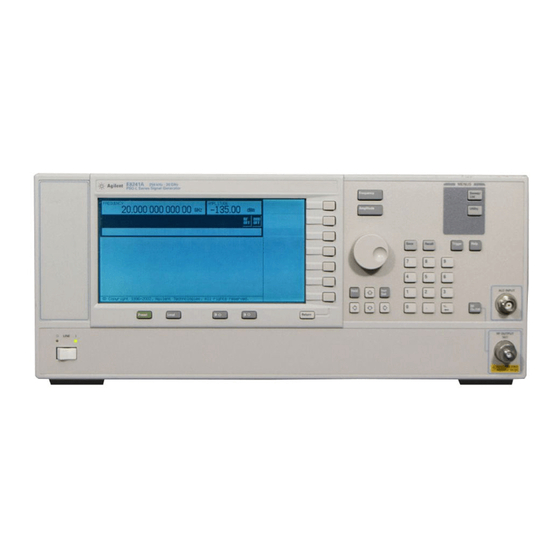
- Page 1 Installation Note Agilent Technologies PSG Series Signal Generators E8241A, E8244A, E8251A, and E8254A Add Option 1E1 (Attenuator) Upgrade Kit Kit Part Number: E8251-60088 Part Number E8251-90045 Printed in USA November 2002...
- Page 2 The information contained in this document is subject to change without notice. Agilent Technologies makes no warranty of any kind with regard to this material, including but not limited to, the implied warranties of merchantability and fitness for a particular purpose. Agilent Technologies shall not be liable for errors contained herein or for incidental or consequential damages in connection with the furnishing, performance, or use of this material.
- Page 3 PSG Series Signal Generators E8241A, E8244A, E8251A, and E8254A Add Option 1E1 (Attenuator) Upgrade Kit Part Number: E8251-60088 Product Affected: ......
-
Page 4: Installation Kit Parts List
Installation Kit Parts List Item Quantity Description Part Number Attenuator 115dB E8251-60070 Semi Rigid Cable (40GHz) E8251-20025 Semi Rigid Cable (20GHz) E8251-20026 Semi Rigid Cable (20GHz) E8251-20027 Semi Rigid Cable (40GHz) E8251-20028 Mounting Screw 0515-1035 Label 7120-1232 Installation Note E8251-90045 Tools Required •... - Page 5 Checking Signal Generator Functionality Use the following procedure to confirm that the signal generator powers up and that the internal check identifies no errors. The internal check evaluates the operation of the signal generator and returns an error message if it detects a problem. NOTE When signal generators with Option 1E5 are first connected to ac line power, the error message ERROR 514, Reference Oven Cold occurs, which causes both the OVEN COLD...
-
Page 6: Tools Required
Removing Outer and Inner Covers Tools Required • T-10 driver • T-15 driver • T-20 driver Removing the Outer Cover Refer to Figure 1. Disconnect the power cord. 2. Using a T-20 driver, remove the two strap handles (1) by loosening the screws (2). 3. - Page 7 Figure 1 Outer Instrument Cover Removal...
- Page 8 Figure 2 Inner Instrument Cover Removal...
-
Page 9: Installation Procedure
Installation Procedure Remove the RF Cable from the Coupler Detector to the RF Output Connector 1. Position the signal generator with the A31 Motherboard facing you and the RF deck on top. 2. Using a 5/16” open wrench, remove the semi-rigid RF cable connecting the A23 Coupler Detector to the RF output connector. - Page 10 Figure 3 AT1 dB 115 Attenuator (Option 1E1)
- Page 11 Activate Option 1E1 1. Reconnect the power cord. 2. Turn the instrument on and let it warm up for 5 minutes. 3. To activate Option 1E1; a. go to the PSG (E8200) service home page at the following URL: http:mktwww.soco.agilent.com/field/service/sources/psg/kits/litlist.htm b.
- Page 12 1. Turn the instrument on and let it warm up for 20 minutes. 2. Using Tables 4-1 and 4-2 in the Post-Repair chapter of the PSG Series Service Guide (part number E8251-90030) complete the adjustments, in the order listed, for the A10 ALC and the AT1 115 dB Attenuator.