
Subscribe to Our Youtube Channel
Related Manuals for Intel SR6850HW4 - Server Platform - 0 MB RAM


Summary of Contents for Intel SR6850HW4 - Server Platform - 0 MB RAM
- Page 1 ® Intel Server Platforms SR6850HW4 and SR6850HW4/M Product Guide Order Number: C92649-005 ® A guide for Technically Qualified Assemblers of Intel Identified Subassemblies/Products.
- Page 2 Intel products including liability or warranties relating to fitness for a particular purpose, merchantability, or infringement of any patent, copyright or other intellectual property right. Intel products are not intended for use in medical, life saving, or life sustaining applications. Intel may make changes to specifications and product descriptions at any time, without notice.
-
Page 3: Preface
Intel® Server Platforms SR6850HW4 and SR6850HW4/M. For the latest version of this manual, see http://support.intel.com/support/motherboards/server/... -
Page 4: Additional Information And Software
Server Management server For drivers Driver (for an extensive list of drivers available) Operating System Driver (for operating system drivers) For firmware and BIOS updates Firmware Update For diagnostics test software Diagnostics Intel® Server Platforms SR6850HW4 and SR6850HW4/M Product Guide... -
Page 5: Safety Information
EMC Testing If the server board set is to be integrated into a non-Intel chassis, make sure that the chassis, power supply, and other modules have passed EMC testing using the server board set with a microprocessor from the same family (or higher) and operating at the same (or higher) speed as the microprocessor used on this server board. - Page 6 AC outlet, the safety-grounding conductor in the power cord provides proper grounding only for the server. Users must provide additional, proper grounding for the rack and other devices installed in it. Intel® Server Platforms SR6850HW4 and SR6850HW4/M Product Guide...
- Page 7 VDE certified or HAR rated 250V, 3 x 1.0mm2 minimum conductor size with IEC 320 C19 and C20 connectors, and rated for no less than the product ratings. Cord length and flexibility: Cords must be less than 4.5 meters (14.76 feet) long. Intel® Server Platforms SR6850HW4 and SR6850HW4/M Product Guide...
- Page 8 Do not attempt to modify or use an AC power cord that is not the exact type required. Surge Suppressor Recommendations: In geographic regions that are susceptible to electrical storms, we highly recommend that you plug the server into a surge suppressor. Intel® Server Platforms SR6850HW4 and SR6850HW4/M Product Guide...
-
Page 9: Safety Cautions
Read all caution and safety statements in this document before performing any of the instructions. ® ® See also Intel Server Boards and Server Chassis Safety Information on the Intel Server Platforms SR6850HW4 and SR6850HW4/M Deployment Toolkit CD and/or at http://support.intel.com/support/motherboards/server/sb/cs-010770.htm. - Page 10 Provided with a properly grounded wall outlet. Provided with sufficient space to access the power supply cord(s), because they serve as the product’s main power disconnect. Intel® Server Platforms SR6850HW4 and SR6850HW4/M Product Guide...
-
Page 11: Wichtige Sicherheitshinweise
Wichtige Sicherheitshinweise Lesen Sie zunächst sämtliche Warn- und Sicherheitshinweise in diesem Dokument, bevor Sie eine ® der Anweisungen ausführen. Beachten Sie hierzu auch die Sicherheitshinweise zu Intel ® Serverplatinen und -Servergehäusen auf der Intel Server Platforms SR6850HW4 and SR6850HW4/M Deployment Toolkit CD oder unter http://support.intel.com/support/motherboards/server/sb/cs-010770.htm. - Page 12 Stromanschluß des Produkts hauptsächlich über die Kabel unterbrochen wird. 重要安全指导 ® 在执行任何指令之前,请阅读本文档中的所有注意事项及安全声明。参见Intel Server Platforms SR6850HW4 and SR6850HW4/M Deployment Toolkit CD(资源光盘) Intel 和/或http://support.intel.com/support/motherboards/server/sb/cs-010770.htm 上的 Server Boards and Server Chassis Safety Information (《Intel 服务器主板与服务器机箱安全信息》)。 Intel® Server Platforms SR6850HW4 and SR6850HW4/M Product Guide...
- Page 13 Revissez solidement les panneaux du boîtier avec les vis retirées plus tôt. Remettez le cadenas en place et verrouillez-le afin de prévenir tout accès non autorisé à l’intérieur du système. Rebranchez tous les cordons d’alimentation c. a. et câbles externes au système. Intel® Server Platforms SR6850HW4 and SR6850HW4/M Product Guide...
- Page 14 Muni d'une prise murale correctement mise à la terre. Suffisamment spacieux pour vous permettre d'accéder aux câbles d'alimentation (ceux-ci étant le seul moyen de mettre le système hors tension). Intel® Server Platforms SR6850HW4 and SR6850HW4/M Product Guide...
-
Page 15: Instrucciones De Seguridad Importantes
Instrucciones de seguridad importantes Lea todas las declaraciones de seguridad y precaución de este documento antes de realizar cualquiera de las instrucciones. Vea Intel® Server Boards and Server Chassis Safety Information ® en el Intel Server Platforms SR6850HW4 and SR6850HW4/M Deployment Toolkit CD y/o en http://support.intel.com/support/motherbords/server/safecert.htm. - Page 16 Provisto de una toma de tierra correctamente instalada. Provisto de espacio suficiente como para acceder a los cables de alimentación, ya que éstos hacen de medio principal de desconexión del sistema. Intel® Server Platforms SR6850HW4 and SR6850HW4/M Product Guide...
- Page 17 Esiste il pericolo di un esplosione se la pila non viene sostituita in modo corretto. Utilizzare solo pile uguali o di tipo equivalente a quelle consigliate dal produttore. Per disfarsi delle pile usate, seguire le istruzioni del produttore. Intel® Server Platforms SR6850HW4 and SR6850HW4/M Product Guide...
- Page 18 In caso di temporali, scollegare le linee di comunicazione dal modem. Dotata di una presa a muro correttamente installata. Dotata di spazio sufficiente ad accedere ai cavi di alimentazione, i quali rappresentano il mezzo principale di scollegamento del sistema. Intel® Server Platforms SR6850HW4 and SR6850HW4/M Product Guide...
-
Page 19: Table Of Contents
Plugging the Server into AC Power..................59 Powering On the Server......................59 Shutting Down the Server ..................... 60 ® 3 Intel Server Deployment Toolkit..............61 Running Software Utilities from the CD................. 61 4 Server Platform Utilities................62 BIOS Setup Utility ......................... 62 BIOS Setup Utility Page Layout ................... - Page 20 5 User Serviceable Platform Components..........138 Tools and Supplies Needed ....................138 Equipment Log ......................138 Removing and Installing the Top Cover ................138 Removing the Top Cover ................... 139 Installing the Top Cover ..................... 140 Intel® Server Platforms SR6850HW4 and SR6850HW4/M Product Guide...
- Page 21 Processor VRM Requirements................... 179 Removing a Processor Thermal Blank............... 180 Installing a Processor Thermal Blank................. 182 Installing and Removing a Processor.................. 183 Removing a Processor ....................183 Installing a Processor ....................184 Intel® Server Platforms SR6850HW4 and SR6850HW4/M Product Guide...
- Page 22 Removing the Power Distribution Board ..............217 Installing the Power Distribution Board ..............218 Replacing the Front Panel I/O Board .................. 219 Removing the Front Panel I/O Board ................. 219 Installing the Front Panel I/O Board ................220 Intel® Server Platforms SR6850HW4 and SR6850HW4/M Product Guide...
- Page 23 Electromagnetic Compatibility Notices................260 FCC (USA) ......................... 260 Industry Canada (ICES-003) ..................261 Europe (CE Declaration of Conformity)..............261 VCCI (Japan) ......................262 BSMI (Taiwan)......................262 Korean RRL Compliance.................... 262 Regulated Specified Components................263 Intel® Server Platforms SR6850HW4 and SR6850HW4/M Product Guide...
- Page 24 Contents Getting Help ..................... 264 ® Intel Server Issue Report Form ..............267 Warranty......................270 Intel® Server Platforms SR6850HW4 and SR6850HW4/M Product Guide...
- Page 25 Figure 43. System Configuration Wizard Start Screen ............. 107 Figure 44. Selection Screen for Server Configuration Utilities..........108 Figure 45. System Configuration Wizard Start Screen ............. 109 Figure 46. Choosing Diskette Type................... 110 Intel® Server Platforms SR6850HW4 and SR6850HW4/M Product Guide...
- Page 26 Figure 91. Installing the Center Brace ..................177 Figure 92. Removing Thermal Blank ..................180 Figure 93. Installing Thermal Blank ..................182 Figure 94. Open Processor Socket Lever................. 184 Figure 95. Set Processor into Socket ..................185 Intel® Server Platforms SR6850HW4 and SR6850HW4/M Product Guide...
- Page 27 Figure 123. Installing the Front Panel I/O Board............... 220 Figure 124. Removing the Battery .................... 222 Figure 125. Interconnect Block Diagram................... 228 Figure 126. AC Power Input Connector ..................239 Figure 127. Main Board Jumper Locations ................242 Intel® Server Platforms SR6850HW4 and SR6850HW4/M Product Guide...
- Page 28 Table 25. BIOS Recovery Beep Codes ............... 251 Table 26. Equipment Log .................... 252 Table 27. Symptom/Cause/Solution Troubleshooting Guide........254 Table 28. Product Certification Markings..............259 Table 29. Product Certification Markings..............260 Intel® Server Platforms SR6850HW4 and SR6850HW4/M Product Guide...
-
Page 29: Part I: User's Guide
Part 1: User’s Guide describes the server platform and procedures that DO NOT REQUIRE the services of a qualified service technician. ® Section 1 provides a brief overview of the Intel Server Platforms SR6850HW4 and SR6850HW4/M, focusing on the chassis features. In this chapter, you will find a list of the server board/chassis features, photos of the product, and product diagrams to help you identify components and their locations. -
Page 30: Platform Description
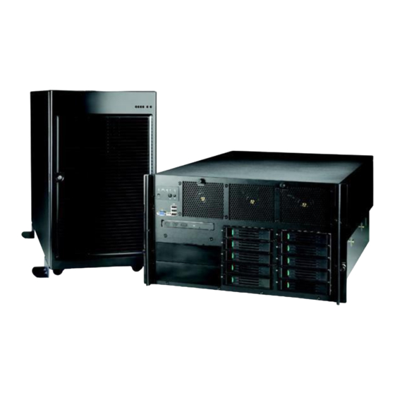
® The Intel Server Platforms SR6850HW4 and SR6850HW4/M are rack-mount or pedestal systems ® ® with support for one to four Intel Xeon processors and 64GB DDR2 400MHz SDRAM memory. ® The system is based on the Intel Server Board Sets SE8500HW4 and SE8501HW4, which in turn ®... -
Page 31: Figure 2. Chassis Front View (Pedestal Configuration)
Figure 2 shows the front view of the chassis in the pedestal configuration with the optional snap-on bezel in place. When the bezel is removed, the user has access to the front panel, hard drives, and peripherals. The default configuration is the rack configuration. You must install the pedestal conversion kit to use your server platform in the pedestal configuration. -
Page 32: Platform Features
Six hot-swap system fans in a redundant (5+1) configuration Ten hot-swap 1-inch Ultra320* SCSI hard disk drives Four hot-plug memory boards (OS support required) RAID on MotherBoard (ROMB) with a battery-backed DDR2 400MHz DIMM for disk cache Intel® Server Platforms SR6850HW4 and SR6850HW4/M Product Guide... -
Page 33: Platform Front
Feature Description ® Manageability Server Management support via Intel Management Module Remote management Emergency Management Port (EMP) Intelligent Platform Management Interface (IPMI) 1.5 compliant, partial IPMI 2.0 compliance Wired For Management (WfM) 2.0 compliant Remote diagnostics support Front control panel... -
Page 34: Standard Control Panel
Amber Fast Blinking Hard drive rebuild interrupted (~2.5 Hz) or rebuild on empty slot. B, C LAN1, LAN2 Status LEDs (green) Indicates LAN activity status. Idle Inactive No access Blinking Active Access Intel® Server Platforms SR6850HW4 and SR6850HW4/M Product Guide... -
Page 35: Figure 4. Front Panel Controls And Indicators
Description System Status/Fault LED Indicates system status. (green/amber) Not ready AC Power Off, POST error Green, On Ready System booted and ready Green, Degraded Processor or DIMM disabled Blinking Amber, On Critical Alarm Critical Power Supply, Blower, Voltage, or Temperature failure. -
Page 36: Intel ® Local Control Panel
Amber, Blinking Non-critical Redundant power supply or Alarm blower failure. Non-critical blower, voltage, or temperature failure. J, K LAN1, LAN2 Status LEDs Indicates LAN activity status. (green) Idle Intel® Server Platforms SR6850HW4 and SR6850HW4/M Product Guide... -
Page 37: Platform Rear
Hard drive rebuild (~2.5 Hz) interrupted or rebuild on empty slot System Reset button Resets the system ® Figure 5. Intel Local Control Panel Platform Rear The figure below shows the features found at the rear of the platform. TP01507 Item Description Video port, standard VGA compatible, 15-pin connector Serial port connector. -
Page 38: Figure 6. Rear Accessible Components
Amber On – 1000 Mbps AC input power connector Power supply LEDs Power supply release Active power supply blank System ID LED (blue) DC Jack Server Management RJ-45 connector (GCM) Figure 6. Rear Accessible Components Intel® Server Platforms SR6850HW4 and SR6850HW4/M Product Guide... -
Page 39: Processors
Processors ® ® The Intel® Server Platform SR6850HW4 supports from one to four 64-bit Intel Xeon Processor ® ® MP with 1MB L2 Cache or 64-bit Intel Xeon Processor MP with 8MB L3 Cache. These processors are targeted for multiprocessor servers. Several architectural and microarchitectural enhancements have been added to this processor, including an increased L2 cache size and an ®... -
Page 40: Available Memory Configurations
This configuration allows for hot-replacement of failing memory boards and hot-add and hot- replacement of memory DIMMs. Intel® Server Platforms SR6850HW4 and SR6850HW4/M Product Guide... - Page 41 The server BIOS also includes two additional memory reliability, accessibility, and serviceability (RAS) features: Memory Sparing: A rank on each memory board can be reserved as a “spare” and can only be used as a backup for other ranks on the same memory board. The memory rank that is configured as spare is held in reserve and cannot be used by the operating system.
-
Page 42: Power Subsystem
This feature allows the system to be powered by two separate AC sources. In the 1+1 configuration, the system continues to operate without interruption if one of the AC sources fails. Intel® Server Platforms SR6850HW4 and SR6850HW4/M Product Guide... -
Page 43: Figure 7. Power Supply Indicators
Each power supply module has three status LEDs located next to the input connector, as shown in Figure 7. TP01509 Location Purpose Description A (Top) Power Good LED This green LED is driven by internal circuitry and is lit whenever the (green) power is turned on. -
Page 44: Cooling Subsystem
The processor heatsink baffle must always be in place. Systems that are not fully configured with four processors and four memory boards must keep the processor heatsink and memory board fillers installed to maintain proper cooling. Intel® Server Platforms SR6850HW4 and SR6850HW4/M Product Guide... -
Page 45: Hot-Swap Pci Slots
Hot-swap PCI Slots The five hot-plug PCI slots each have power and attention LEDs. The Attention button is used to invoke a hot-plug sequence to remove or add an adapter without having to use the software interface. They are located by the green arrow on the PCI divider label. The status of the LEDs is shown in Table 2 and Table 3. -
Page 46: Peripherals
Platform Description Peripherals The Intel® Server Platform SR6850HW4 supports the following peripheral devices: Ten hot-swap hard drives bay (1-inch Ultra320* SCSI) One ½-inch IDE DVD/CD-ROM Two full-height tape back-up devices. TP01508 Item Description Video connector. USB ports (three). Front panel control module. Standard module shown. -
Page 47: Hard Disk Drive Support
Hard Disk Drive Support NOTE Because hard disk drives have different cooling, power and vibration ® characteristics, Intel validates specific hard disk drive types in the Intel ® Server Platform SR6850HW4. See the Intel Server Platform SR6850HW4 Tested Hardware and Operating System List for a list of the supported drives. -
Page 48: Removable Media Bay Support
In addition, the server contains the following system boards: Front panel board SCSI backplane board Power distribution board SATA-to-IDE Adapter board The following figure shows a block diagram of the system and the board set within the system. Intel® Server Platforms SR6850HW4 and SR6850HW4/M Product Guide... -
Page 49: Figure 12. Server Platform Block Diagram
Figure 12. Server Platform Block Diagram... -
Page 50: Main Board
Platform Description Main Board The main board consists of the Intel® E8500 chipset, four memory board connectors, and slots for ® PCI Express* and PCI-X* adapters. The board also has support for the Intel Management Module, a custom Fibre Channel module connector, on-board video, Gigabit ethernet, USB2.0, Serial-ATA, Ultra320* SCSI, dual flash memory components for BIOS, and RAID On Motherboard (ROMB) support. -
Page 51: Figure 13. Main Board Component Locations
Figure 13. Main Board Component Locations The main board supports the following: ® ® ® ® Up to four 64-bit Intel Xeon processor MP with 1MB L2 Cache or 64-bit Intel Xeon processor MP with 8MB L3 Cache ® Intel E8500 chipset ® Intel E8500 Northbridge: has two shared 64-bit FSB interfaces configured for symmetric multiprocessing. -
Page 52: Scsi Controller
SCSI device. SCSI port A from the LSI* ® 53C1030 controls the internal SCSI channel. The internal channel is routed to the Intel Server Platform SR4850HW4 SCSI backplane board via a SCSI U320 cable. The internal channel has been validated only for LVDS operation. -
Page 53: Video Support
Video Support ® The Intel Server Board SE8500HW4 Main Board features the ATI Radeon 7000 Embedded Video Controller with 16MB of video RAM. The Radeon 7000 provides the following features: 2D/3D/video accelerator Dual DAC for integrated, cost-effective multi-panel support DVI compliant integrated 165MHz TMDS transmitter... -
Page 54: Memory Board
LED off: The DIMM is functioning properly. DIMM 2A Status LED LED on: Error LED for DIMM slot 2A (J3B2). The DIMM is (amber) malfunctioning and needs to be replaced. LED off: The DIMM is functioning properly. Intel® Server Platforms SR6850HW4 and SR6850HW4/M Product Guide... -
Page 55: Front Panel I/O Board
Figure 14. Hot-Plug Memory Board LEDs Front Panel I/O Board ® The Intel Server Platform SR6850HW4 Front Panel I/O board provides access to the video and USB interfaces. TP01488 Front panel board connector Figure 15. Front Panel Board Component Location ®... -
Page 56: Scsi Backplane Board
Two standard 68-pin SCSI connectors provide two independent SCSI bus connections to the main board Ten 80-pin SCA-2 blind-mate connectors to mate with SCSI drives on the two buses Enclosure management SCSI Accessed Fault-Tolerant Enclosures (SAFTE) Interface Specification SCSI Power Control Intel® Server Platforms SR6850HW4 and SR6850HW4/M Product Guide... -
Page 57: Power Distribution Board
LED control logic Server management I C interface Fan presence sensing and fan fault LED control C Serial EEPROM (FRU) Temperature sensors SAFTE controller firmware update capability Interconnect for optional LCD front panel control board Voltage regulators 12VDC to 5VDC 5VDC to 3.3VDC 5VDC to 1.8VDC System fan control for six fans... - Page 58 In this platform, the BMC is also the chassis bridge controller, providing integrated ICMB support. ICMB transports server management information between chassis in a cluster configuration that can contain multiple servers and peripherals. Intel® Server Platforms SR6850HW4 and SR6850HW4/M Product Guide...
-
Page 59: Starting Up And Shutting Down The Server
NOTE ® When installing a new Intel Management Module ensure to update the BMC with the correct server firmware. The firmware is updated after the server is powered on. Using incorrect BMC firmware may affect operation of the front control panel’s power button. -
Page 60: Shutting Down The Server
The +3.3V standby power is still available to the system even when it is not running. To remove standby power from the system, unplug all power cords from the system. Intel® Server Platforms SR6850HW4 and SR6850HW4/M Product Guide... -
Page 61: Intel Server Deployment Toolkit
To create a DOS-bootable CD ROM see the instructions that came with your CD ROM burning software. Running Software Utilities from the CD ® The following procedure allows you to run the software utilities directly from the Intel Server Platforms SR4850HW4 and SR6850HW4 Deployment Toolkit CD. ®... -
Page 62: Server Platform Utilities
4 Server Platform Utilities BIOS Setup Utility The BIOS Setup Utility is a text-based utility that allows you to configure the system and view and change device settings and view environmental information for the platform. The BIOS Setup Utility interface consists of several screens, called pages. Each page contains information or links to other pages. -
Page 63: Keyboard Commands
Keyboard Commands The bottom right portion of the Setup screen provides a list of commands that are used to navigate through the BIOS Setup Utility. These commands are context sensitive. The Keyboard Command Bar supports the following key presses: Table 5. BIOS Setup: Keyboard Commands Option Description... -
Page 64: Configuring Memory Options
9. Go back to the memory menu option and enter a sparing threshold, between 1 and 15. 10. Select View and Configure Memory Board X option, where X is the memory board that is to be enabled as the spare. 11. Verify Board Status displays “Healthy”. Intel® Server Platforms SR6850HW4 and SR6850HW4/M Product Guide... -
Page 65: Memory Raid
12. Set the Reserve Rank for Spare to “Enabled”. 13. Press <F10> to save changes and exit. 14. Press “Y” at the prompt to save the changes. The server reboots to activate the changes. Memory RAID If the server contains four memory boards with equal memory capacity, the system can be configured for Memory RAID. -
Page 66: System Configuration Reset
A second method to send a reset system configuration request to the server is to use the NVRAM_CLR jumper at location J4A4 on the main board. See letter “A” in Figure 17 to locate the jumper block. Use the instructions following the diagram. Intel® Server Platforms SR6850HW4 and SR6850HW4/M Product Guide... -
Page 67: Figure 17. Jumper Locations
Password BIOS Write BIOS NVRAM Clear Protect Recovery Clear Default Default Default Default Enabled Enabled Enabled Enabled J4A1 J4A2 J4A3 J4A4 Circuit Breaker Type Default 100 V 15 A J4J3 CPU 3 CPU 4 CPU 2 CPU 1 TP01446 Figure 17. Jumper Locations 1. -
Page 68: Bios Upgrades And Recovery
BIOS Upgrades iflash32 NOTE A BIOS upgrade procedure can also be done with the latest available System Update Package (SUP) for the Intel® Server Platform SR6850HW4 and SR6850HW4/M. This package is available at: http://support.intel.com/support/motherboards/server/s/ Intel® Server Platforms SR6850HW4 and SR6850HW4/M Product Guide... -
Page 69: Table 6. Iflash32 Utility Command-Line Options And Parameters
Use the iflash32 utility to upgrade the BIOS by following these steps: 1. Boot to DOS. 2. Copy the iflash32.exe and the binary input file to a USB flash memory device. 3. Run the iflash32 utility through the command-line interface: Run the utility by entering the command iflash32 [Filename] [Options]. -
Page 70: Bios Recovery
Automatic recovery may be due to any of the following conditions: Flash integrity check failure: This includes corrupted header of the main BIOS or bad checksum. Incompatible versions of the recovery BIOS and the main BIOS. Intel® Server Platforms SR6850HW4 and SR6850HW4/M Product Guide... -
Page 71: Rolling Bios
Rolling BIOS With the Rolling BIOS feature, two copies of the BIOS are stored on the main board. These are designated as the primary and secondary BIOS image. The primary image is the BIOS in use. The BIOS normally boots to this primary image. BIOS updates are diverted to the secondary image. -
Page 72: Keystroke Mappings
ExitBootServices. The operating system is responsible for continuing the Console Redirection after that point. BIOS console redirection is a text console and any graphical data such as a logo are not redirected. Intel® Server Platforms SR6850HW4 and SR6850HW4/M Product Guide... -
Page 73: Interface To Server Management
Interface to Server Management If BIOS determines that console redirection is enabled, it passes the baud rate through the Intelligent Platform Management Bus (IPMB) to the appropriate management controller. Sample Setup for Console Redirection Below is an example of how to configure the console/host and server for console redirection. In this example, the console is running under Windows. -
Page 74: Lsi Logic* Mpt Scsi Utility
System Options Menu screen. The LSI Logic* MPT SCSI Utility main menu appears as shown in the figure below. Figure 18. LSI SCSI Utility Main Menu Press <F2> to select “Menu”. This provides access to the menu options “Boot Adapter List” and “Global Properties”. Intel® Server Platforms SR6850HW4 and SR6850HW4/M Product Guide... -
Page 75: Figure 19. Boot Adapter List
The boot adapter list allows you to add or remove boot adapters. This screen is shown by the figure below. Figure 19. Boot Adapter List The Global Properties List screen allows you to set the properties for all adapters being controlled. This screen is shown by the following figure. - Page 76 Scanning for devices… NOTE If the RAID on Motherboard (ROMB) feature is not enabled, the following message will be displayed: Current Firmware does not support IME RAID type. Press any key to continue. Intel® Server Platforms SR6850HW4 and SR6850HW4/M Product Guide...
-
Page 77: Figure 21. Adapter Properties
Figure 21 shows the adapter properties and the configuration settings. Figure 21. Adapter Properties The following list shows the available options for each setting category. <Device Properties>: Takes you to the Device Properties menu shown in Figure 22 on the following page. -
Page 78: Figure 22. Device Properties
Scan Luns >0: “[Yes]” or “[No]” Disconnect: “[On]” or “[Off]” SCSI Timeout: “[<10>]” Queue Tags: “[On]” or “[Off]” <Restore Defaults>: Discards all changes. No warning message is provided before discarding the changes. Intel® Server Platforms SR6850HW4 and SR6850HW4/M Product Guide... -
Page 79: Figure 23. Adapter And/Or Device Properties Exit Menu
If you made changes before choosing to exit this menu, the Exit menu provides three options: “<Cancel Exit>”, “<Save Changes then exit this menu>”, and “<Discard changes then exit this menu>”. To exit the utility, select “<Exit the Configuration Utility>”. After exiting, the system will reboot. -
Page 80: Platform Confidence Test
(cables broken or improperly seated, etc.) when installed components are not reported. Installing the Platform Confidence Test Use the following steps to install the PCT on your Intel® Server Platforms SR6850HW4 and SR6850HW4/M: ® 1. Insert the Intel Server Platforms SR4850HW4 and SR6850HW4 Deployment Toolkit CD into a Windows* based system. -
Page 81: Platform Confidence Test Options
The System Configuration Wizard (SCW) is a combination of software applications, batch files and helper applications that help you with the initial configuration of your Intel-based server. The SCW supports IPMI 2.0, 1.5, and later compatible platforms. It performs the following activities: Set the system time and date in the BIOS. -
Page 82: Starting The System Configuration Wizard
The Intel® Server Management software will allow you to configure these items later, from the operating system. The SCW will ask you if you are using Intel® Server Management software and not prompt you to configure these items if you are using Intel® Server Management. -
Page 83: Using The Server Configuration Wizard Option
BIOS and the BMC. The SCW asks first if Intel® Server Management is installed on this server. If you select Yes, the SCW does not ask you about configuring LAN channel 1, the serial channel, or users. If you select No, you are given the option to configure these items through the SCW. -
Page 84: Figure 25. Configuration Options
Configure Advanced Features on this server: The Configure Advanced Features checkbox allows you to configure the Advanced Features of an Intel® Management Module – Advanced Edition system configuration. This option is available only on a system that uses the Intel® Management Module – Advanced Edition. -
Page 85: Configuring Sdrs And Frus
® If your server has the Intel Management Module – Advanced Edition installed, the following options are included by default: Load FRUs and SDRs onto this server Configure Channels on this server Configure Users on this server Configure Advanced Features on this server After you decide which of the options to program and press the Continue button, the SCW will exit from the graphical user interface mode and begin programming the options. -
Page 86: Configuring Channels
If your server has the Intel Management Module – Professional Edition, one LAN ® channel, and one serial modem channel are supported. If your server has the Intel Management Module – Advanced Edition, your server supports one LAN channel, one serial modem channel, and one advanced LAN channel. -
Page 87: Figure 27. Lan Channel Setup Screen 1
LAN Channel Configuration Screen 1 – LAN IP Setup Figure 27. LAN Channel Setup Screen 1 When this screen is displayed, the settings shown are the current settings for this LAN channel on the server. Unless otherwise noted, all fields on this screen must have valid data entered into them. The Continue button is disabled/grayed out until all of the edit boxes on the screen are filled in. -
Page 88: Figure 28. Gateway Mac Address Resolution
IP address. Press this button if the resolution attempt failed because the server was not connected to the network. You will see the same dialog box when resolving the Backup Gateway MAC Address. Intel® Server Platforms SR6850HW4 and SR6850HW4/M Product Guide... -
Page 89: Figure 29. Lan Channel Setup Screen 2
LAN Channel Configuration Screen 2 –Server Management and Serial Over LAN Setup This screen allows you to continue to enter the necessary settings to configure the specified LAN channel. Figure 29. LAN Channel Setup Screen 2 When this screen is displayed, the settings shown are the current settings for this LAN channel on the server. - Page 90 255. SOL Baud Rate: The SOL Baud Rate dropdown list allows you to set SOL baud rate desired. The valid choices are 9600bps, 19.2kbps, 38.4kbps, 57.6kbps or 115.2kbps. Intel® Server Platforms SR6850HW4 and SR6850HW4/M Product Guide...
-
Page 91: Figure 30. Lan Channel Setup Screen 3
LAN Channel Configuration Screen 3 – LAN Alerting Setup This screen allows you to continue to enter the necessary settings to configure the specified LAN channel. Figure 30. LAN Channel Setup Screen 3 Enable LAN Alerting: Allows you to configure the LAN alert settings for this LAN channel on the server. - Page 92 Address 1 radio button allows you to specify that all LAN alerts configured to go the first alert IP address are instead to be sent as emails. This option is available only on the Intel® Management Module– Advanced Edition system configuration.
-
Page 93: Configuring The Serial/Modem Channel
Clear All: This button will clear all of the filter checkboxes on the dialog. Configuring the Serial/Modem Channel The Serial/Modem channel option is available on both the Intel® Management Module– Professional Edition and Intel® Management Module– Advanced Edition system configurations. -
Page 94: Figure 32. Modem Configuration
Modem Dial Command: The Modem Dial Command edit box allows you to enter the modem dial command string. This string is transmitted every time a Platform Event Page is sent. This string is sent before the paging string to indicate to the modem how to dial. Intel® Server Platforms SR6850HW4 and SR6850HW4/M Product Guide... -
Page 95: Figure 33. Remaining Serial/Modem Configuration Parameters
Serial/Modem Configuration Screen 2 - Configuring Remote Server Management Options for a Serial / Modem Connection This screen allows you to continue to enter the necessary settings to configure the serial/modem channel. Figure 33. Remaining Serial/Modem Configuration Parameters Enable Access: The Enable Access checkbox allows you to enable or disable Serial/Modem connectivity. -
Page 96: Figure 34. Configuring Serial Alerts
Paging String is determined at run time. The paging string is concatenated with the Alert Destination Phone Number entered on this screen. Therefore, it is not necessary to enter the Alert Destination Phone Number with the Paging String. Intel® Server Platforms SR6850HW4 and SR6850HW4/M Product Guide... -
Page 97: Figure 35. Configuring Serial Alert Filters
Blackout Period Edit Box: The Blackout Period edit box allows you to enter the time, in minutes, between successive pages. The valid range is [0 – 255] where 0 disables the blackout period. Alert Paging Filters: If you press the Alert Paging Filters button, the SCW will display the following screen with which you can check the filters that are to be used when sending out alerts. -
Page 98: Select Users To Configure Screen
The Configure Users Screen provides a mechanism for configuring user access to LAN and Serial/Modem channels. A maximum of four users are supported by the Intel® Server Platforms SR6850HW4 and SR6850HW4/M. The screens allow configuration of user settings like username, password, and the per-channel configuration for each user. -
Page 99: Configure Users Screen
Configure Users Screen The Configure Users Screen provides a mechanism for configuring user access to LAN and Serial/Modem channels. The maximum number of users that can be configured for a system depends on that system. The screens allow configuration of user settings like username, password, and the per-channel configuration for each user. - Page 100 Advanced LAN Channel Privilege Level Limit: The Advanced LAN Channel Privilege Level dropdown list allows you to select the privilege level for the Advanced IMM LAN channel ® access for the user being configured. This option is available only on the Intel Management Module – Advanced Edition system configuration.
-
Page 101: Setting A System Asset Tag
Setting a System Asset Tag The screen below allows you to enter the asset tag for the server. The asset tag is a string that is the identification number or serial number that has been assigned to the server. The asset tag can contain text as well as numbers. -
Page 102: Configuring The Advanced Features
Advanced Features are configured through three main screens and several sub-screens. Each screen displays the configuration options for one or more of the advanced features. The Advanced Features are available only on the platform configuration that uses the Intel® Management Module– Advanced Edition. - Page 103 SNMP Settings The BMC SNMP (Simple Network Management Protocol) feature provides a way for basic server management information access and control operations to be available Out Of Band (OOB). This allows server management without requiring any operating system agents and provides for Pre-OS and operating system hung operation.
-
Page 104: Figure 40. Advanced Features Configuration Screen 2
1 – 65535. HTTP Host Name: The HTTP Host Name edit box allows the HTTP Host Name for this server to be set. The HTTP Host Name is the domain name of the system. Intel® Server Platforms SR6850HW4 and SR6850HW4/M Product Guide... -
Page 105: Figure 41. Advanced Features Configuration Screen 3
Enable HTTPS: When the HTTPS server is disabled, it closes all open sockets so that the network stack will not accept incoming HTTPS connections. When the HTTPS server is enabled, it will wake up the HTTPS thread, which will open its sockets. If this feature is disabled, none of the other fields is editable. -
Page 106: Saving The Configuration To A Disk
If you check the option to save the server’s configuration, the SCW displays a file save dialog, allowing you to enter a location and file name where the configuration is to be saved. The file/open dialog follows the standard Windows file/open dialog scheme. Intel® Server Platforms SR6850HW4 and SR6850HW4/M Product Guide... -
Page 107: Saving The Configuration To The Server
Saving the Configuration to the Server After each applicable screen has been displayed and you have entered and/or altered the settings, the SCW saves the data to the server. The SCW exits and the BMC Configuration Utility perform this save function. Running Utilities from the SCW If you selected Server Configuration Utilities from the Server Configuration Start Screen, shown below, you will be brought to an area of the utility from which you can run advanced server... -
Page 108: Figure 44. Selection Screen For Server Configuration Utilities
MENU.CNF file on the Intel Server Platforms SR4850HW4 and SR6850HW4 Server Deployment Toolkit CD. When the utility chosen to run has completed its execution, you are returned to the screen from where the utility was launched. Intel® Server Platforms SR6850HW4 and SR6850HW4/M Product Guide... -
Page 109: Creating Diskettes
Creating Diskettes If you selected Create Diskettes from the Server Configuration Start Screen, shown below, you will be brought to an area of the utility from which you can create driver and utility diskettes. Figure 45. System Configuration Wizard Start Screen... -
Page 110: Creating Disk Sets By Operating System
SCW will switch to a DOS screen where you are prompted to insert the appropriate disk as the set is being created. After the diskette set has been created, you are returned to the “Create Operating System Diskettes” screen. Intel® Server Platforms SR6850HW4 and SR6850HW4/M Product Guide... -
Page 111: Device Driver Diskettes
Device Driver Diskettes If you choose “Create Disk Sets by Device/Function,” you will be brought to a screen on which you can select which device drivers or utility installation diskettes you want to create. Until you select an option, the Continue button is disabled /grayed out. After you select the device driver or function and press the Continue button, the Server Configuration SCW will display a message stating how many diskettes are required. -
Page 112: Running The Frusdr Load Utility
Upon completing the programming of the FRU and SDR areas, the server must be rebooted. ® Follow these steps to run the FRUSDR Load Utility from the Intel Server Platforms SR4850HW4 and SR6850HW4 Deployment Toolkit CD: ®... - Page 113 FRU and SDR Load Utility Version 6.2 Usage: FRUSDR /? or /h Displays usage information. /d {smb,fru,sdr} Only displays requested area. /cfg filename.cfg Uses custom CFG file. Pause between blocks of data. Copyright (c) 1997-2004 Intel Corporation, All Rights Reserved...
- Page 114 The Internal Use area is displayed in hex format, with 16 bytes per line. The board, Chassis and Product FRU areas end with an END OF FIELDS CODE, which indicates there is no more data in this area. Intel® Server Platforms SR6850HW4 and SR6850HW4/M Product Guide...
- Page 115 END OF FIELDS CODE Display Board Area Board Information Area (Version 1, Length 64) Unicode Country Base = 00h Manufacturing Time (mins) = 4686915 Manufacturer Name (ASCII) = Intel Product Name (ASCII) = Main board Serial Number (ASCII) = ICHW44700087 Part Number...
- Page 116 FRUSDR Load Utility and to establish a configuration for the product. Some of the commands are user interactive and require you to input a choice when you run the FRUSDR Load Utility. Intel® Server Platforms SR6850HW4 and SR6850HW4/M Product Guide...
-
Page 117: Checking The Fru Data Integrity
After the FRUSDR Load Utility is run with the configuration file and updates are successful, a single message is displayed and the utility exits. If the FRUSDR Load Utility fails, it exits with an error message and an exit code. Loading Specified FRU or SDR Files The normal method of loading one or more FRU or SDR files is through the use of a configuration file. -
Page 118: Sel Viewer Utility
Sort the SEL records by various fields such as timestamp, sensor type number, event description, and generator ID. ® You can run this utility either directly from the Intel Server Platforms SR4850HW4 and SR6850HW4 Deployment Toolkit CD or from a DOS device. To run the utility from a DOS device, copy the following files to a USB flash memory device or to a CD-ROM disk: SELView.exe... -
Page 119: Graphical User Interface
NOTE Additional instructions are available through the SEL Viewer Utility Help menu. When you start the SEL Viewer Utility from the graphical user interface (GUI), you will see a splash screen if the splash screen file is available and in the SEL Viewer Utility search path. No error message is displayed if the splash screen file is not located. -
Page 120: Figure 47. Sel Viewer Utility Main Window
Server Platform Utilities The main window is shown in the following diagram. Figure 47. SEL Viewer Utility Main Window Intel® Server Platforms SR6850HW4 and SR6850HW4/M Product Guide... -
Page 121: Figure 48. Sel Records In Hex Format
The SEL Viewer Utility displays the event logs in either an interpreted, textual form or in raw hexadecimal format as read from the server. You can choose your display format. In the figure below, the hexadecimal format is displayed. Figure 48. SEL Records in HEX Format Table 4 provides the abbreviations that are used in the hexadecimal mode display. -
Page 122: Figure 49. File Open Window
Save As: From the File pull-down menu, the Save As option allows you to save the SEL data to a file, with a file extension of “.sel”. This file is saved in the format in which it is displayed: in interpreted text format or in raw hexadecimal format. Intel® Server Platforms SR6850HW4 and SR6850HW4/M Product Guide... -
Page 123: Figure 50. Sel Properties
The interpreted text format files contain the SEL properties in the first lines followed by a blank line and the column headings. The SEL file format is specified as an ASCII-readable file, with each field delimited to a tab stop and with each system event ending with a carriage return/line feed. -
Page 124: Figure 52. General Help Window
Use the arrow keys to select between topics and use the <F10> or <Tab> keys to move between panes. To dismiss the help window, press <Esc> key. See the figure below for the General Help screen. Figure 52. General Help Window Intel® Server Platforms SR6850HW4 and SR6850HW4/M Product Guide... -
Page 125: Fru Viewer Utility
.STR file is a Unicode file, it allows internationalization of the FRU Viewer Utility. ® You can run this utility either directly from the Intel Server Platforms SR4850HW4 and SR6850HW4 Deployment Toolkit CD or from a DOS device. To run the utility from a DOS device, copy the following files to a USB flash memory device or to a CD-ROM disk: FRUView.exe... -
Page 126: Using The Fru Viewer Utility
Run the utility by typing the command FRUVIEW ® When you start the FRU Viewer Utility from the Intel Server Platforms SR4850HW4 and SR6850HW4 Deployment Toolkit CD graphical user interface (GUI), you will see a splash screen if the splash screen file is available and in the FRU Viewer Utility search path. No error message is displayed if the splash screen file is not located. -
Page 127: Figure 54. Fru Viewer Utility Main Window
The main window is shown in the following figure. Figure 54. FRU Viewer Utility Main Window The Client area of the screen consists of two windows. The first window is the FRU information window. This window displays the following FRU data in a multi-column format: Byte number: The bits for the byte are enclosed by the parentheses. -
Page 128: Figure 55. File Open Dialog Box
<Home>, <End>, Left/Right arrows and <Ins>. The <Ins> key toggles insert and overwrite editing while in the edit box and this is noted with “INS” or “OVR”, displayed in the lower-right corner of the dialog box. Figure 55. File Open Dialog Box Intel® Server Platforms SR6850HW4 and SR6850HW4/M Product Guide... -
Page 129: Figure 56. Fru Menu
Save As: Under the File pull-down menu, Save As provides a way for you to save the currently displayed FRU to a file. If the save fails because the file cannot be created, the following message is displayed: “Unable to create save file”. If an error occurs while writing information to the file, the following message is displayed: “Error saving the FRU data to the file”. -
Page 130: Figure 57. Fru Properties
When the resolution mode is changed, FRU data is read again from the server and displayed. When High resolution mode is selected, the utility displays FRU data as shown in Figure 58 . Figure 58. High Resolution Mode Intel® Server Platforms SR6850HW4 and SR6850HW4/M Product Guide... -
Page 131: Figure 59. Help Window
Help: The Help menu provides options for General Help and About, as described below. General Help: From the Help pull-down menu, General Help provides information about how to use the FRU Viewer. The General Help window is divided into two panes. The top pane lists the main help topics and the bottom pane displays information about the selected topic. -
Page 132: Save And Restore System Configuration (Syscfg)
BMC release 11. Write down the name of the HEX file. You will need it later. Firmwareupdate.txt <name>.txt 2. Boot to DOS. Intel® Server Platforms SR6850HW4 and SR6850HW4/M Product Guide... - Page 133 /dirhsc /u /op /p name.hex NOTES ® A jumper at location J1B1 on the Intel Management Module must cover pins 1 and 2 to update the boot block. Cover pins two and three on this jumper to write-protect the BMC boot block.
-
Page 134: Firmware Update Utility Command-Line Options
Restarts the boot code by exiting firmware transfer mode and re-entering firmware transfer mode after programming the boot code. /noexit The utility will not exit firmware transfer mode after entering it, except when the restart boot option is specified. Intel® Server Platforms SR6850HW4 and SR6850HW4/M Product Guide... -
Page 135: Table 9. Fwpiaupd Command-Line Arguments For Direct Hsc Update
Table 9. FWPIAUPD Command-line Arguments for Direct HSC Update Parameter Description FWPIAUPD The name of the utility. <hexfile> The name of the hex file for the operation. The path can be specified with the filename, e.g. c:\mydir\updatfil.hex. There is no default filename or extension. /? Or /help Displays the command-line help. -
Page 136: Extensible Firmware Interface (Efi) Shell
[-b] [-p prot_id] | [handle] Dumps handle information disconnect DeviceHandle# Disconnects device from driver [DriverHandle# [ChildHandle#] dmem {address] [size] [;MMIO] Displays the contents of memory dmpstore Dumps the variable store drivers [-b] [-lXXX] Displays drivers Intel® Server Platforms SR6850HW4 and SR6850HW4/M Product Guide... - Page 137 Command Description drvcfg [-c] [-lXXX] [-f] [-v] [-s] Invokes the driver configuration protocol drvdiag [-c] [-lXXX] [-s] [-e] [-m] Invokes the driver diagnostics protocol echo [[-on | -off] | [text] Echoes text to the standard output device or toggles script echo edit [filename] Opens the text editor allowing you to create or edit a file eficompress infile outfile...
-
Page 138: Part Ii: Service Guide
Part II: Service Guide Part 2: Service Guide describes procedures that require internal server access. The Service Guide exists for two audiences, Users and Qualified Service Technicians. The User Serviceable Platform Components chapter is intended for both Users and Qualified Server Technicians. -
Page 139: Removing The Top Cover
described in this chapter, all servicing must be done by a qualified service technician. Removing the Top Cover To remove the top cover, follow these instructions: 1. Observe the safety precautions, warnings, and cautions described in “Safety Information”, page 2. If the chassis is rack-mounted, slide the chassis out far enough to expose the entire top cover. 3. -
Page 140: Installing The Top Cover
3. Slide the top cover towards the front of the chassis until it is fully closed. 4. Tighten the captive screws on the faceplate of the chassis. 5. Slide the server into the rack. TP01514 Figure 62. Installing the Top Cover Intel® Server Platforms SR6850HW4 and SR6850HW4/M Product Guide... -
Page 141: Hot-Swapping System Fans
Hot-swapping System Fans The six fans are located at the front of the chassis. You can remove and install these fans without turning off the power to the server. Each fan uses an amber LED to indicate a failed fan condition. If the amber LED is on, the fan module needs to be replaced. -
Page 142: Figure 64. System Fan Location And Removal
6. Set the replacement fan into place. Wait for the replacement fan to spin up. 7. Install the top cover. For instructions, see “Installing the Top Cover”, page 140. TP01515 Figure 64. System Fan Location and Removal Intel® Server Platforms SR6850HW4 and SR6850HW4/M Product Guide... -
Page 143: Hot-Swapping Hard Disk Drives
Hot-swapping Hard Disk Drives The server supports ten hot-swap drive carriers. Each carrier holds a standard one-inch high hard drive (SCSI-2 or SCSI-3). The procedures in this section describe how to determine drive status, remove a faulty drive, and install a new drive. You can install or replace a hot-swap hard disk drive without powering down the server. -
Page 144: Removing A Hard Disk Drive
3. Pull the handle to remove the drive cage from the chassis. See letter “B” in the figure. 4. Place the drive cage on a clean, static-free work surface. TP01566 Figure 66. Removing a Hard Disk Drive Intel® Server Platforms SR6850HW4 and SR6850HW4/M Product Guide... -
Page 145: Mounting A Hard Disk Drive In A Carrier
Mounting a Hard Disk Drive in a Carrier The server supports ten hot-swap drive carriers. Each carrier houses a standard one-inch high hard drive (SCSI-2 or SCSI-3). CAUTION To allow proper airflow and server cooling, all drive bays must contain either a carrier with a hard drive installed or a carrier with an air baffle installed. -
Page 146: Installing A Hard Disk Drive Assembly
3. Use the handle to push the carrier until it docks in the chassis, then close the drive carrier handle. See letter “B” in the figure. TP01569 Figure 69. Installing Hard Disk Drive into Server Intel® Server Platforms SR6850HW4 and SR6850HW4/M Product Guide... -
Page 147: Hot-Swapping Power Supplies
CAUTIONS The Intel® Server Platforms SR6850HW4 and SR6850HW4/M each support up to two power supplies. If your server is configured with a single power supply, you must have an active fan blank installed in the location for the second power supply. -
Page 148: Installing A Power Supply Or An Active Fan Blank
4. Push the handle against the face of the power supply or active fan blank until it is securely held in the power supply bay. TP01574 Figure 71. Removing a Power Supply Intel® Server Platforms SR6850HW4 and SR6850HW4/M Product Guide... -
Page 149: Installing And Removing Pci Cards
5. Plug the power cord into the AC receptacle on the power supply. 6. Use the LEDs on the power supply to ensure power supply function. Installing and Removing PCI Cards This section outlines the procedures for performing a hot-plug operation with PCI cards and installing and removing non-hot-plug PCI cards. -
Page 150: Figure 72. Removing A Pci Card
See letter “C” in Figure 72. To install a replacement PCI card: see “Installing a Hot-plug PCI Add-in Card”, page 152. 12. Install the top cover. For instructions, see “Installing the Top Cover”, page 140. Intel® Server Platforms SR6850HW4 and SR6850HW4/M Product Guide... -
Page 151: Removing Hot-Plug Pci Card With Hardware Hot-Plug Interface
Removing Hot-plug PCI Card with Hardware Hot-Plug Interface CAUTION Only PCI add-in cards in PCI slots 1 through 5 are hot-swappable. If you are adding or removing a PCI card from PCI slot 6 or 7, see “Removing a Non- Hot-Plug PCI Card”... -
Page 152: Installing A Hot-Plug Pci Add-In Card
8. Align and slide the adapter board down until it seats in its connector. If you are installing a full- length card, guide the front of the card into the slot shown by letter “D” in the figure. 9. Press the card down firmly until it seats into the slot. Intel® Server Platforms SR6850HW4 and SR6850HW4/M Product Guide... -
Page 153: Figure 73. Installing A Pci Card
TP01582 Figure 73. Installing a PCI Card CAUTION Some accessory/option board outputs exceed Class 2 or limited power source limits and must use appropriate interconnecting cabling in accordance with the national electrical code during installation. 10. Move the retention latch at the rear of the card slot into the closed position. 11. -
Page 154: Removing A Non-Hot-Plug Pci Card
3. Power down the system and unplug both AC power cords to remove power from the server. 4. Remove the top cover. For instructions, see “Removing the Top Cover”, page 139. 5. Disconnect any cables attached to the PCI card. Intel® Server Platforms SR6850HW4 and SR6850HW4/M Product Guide... -
Page 155: Installing A Non-Hot-Plug Pci Card
6. Push the retention latch at the rear of the card slot to open it. See letter “A” in Figure 72. 7. If a long card is installed, press the blue plastic piece at the front of the card. 8. Pull up on the card to remove it. See letter “B” in the Figure 72. 9. -
Page 156: Installing Or Removing The Fibre Channel Module
7. Push the retention lever at the rear of the Fibre Channel Module slot into the open position. See letter “A” in Figure 74. 8. Pull up on the Fibre Channel Module to remove it. See letter “B” in the figure. TP01497 Figure 74. Removing a Fibre Channel Module Intel® Server Platforms SR6850HW4 and SR6850HW4/M Product Guide... -
Page 157: Installing The Fibre Channel Module
9. Place the Fibre Channel Module inside a static-free plastic bag on a clean, static-free work surface. 10. Install an expansion slot cover over the empty slot or install a replacement Fibre Channel Module: To install an expansion slot cover: align the cover with the slot from the rear of the chassis. Press the cover into the slot. -
Page 158: Figure 75. Installing A Fibre Channel Module
14. Install the memory board or memory board air baffle into Slot C. For instructions, see “Cold Insertion of a Memory Board”, page 165. 15. Install the top cover. For instructions, see “Installing the Top Cover”, page 140. Intel® Server Platforms SR6850HW4 and SR6850HW4/M Product Guide... -
Page 159: Installing And Removing Memory Boards
Installing and Removing Memory Boards Memory boards can be configured in a redundant or a non-redundant configuration. memory boards configured using RAID or mirroring are in a redundant configuration. If a memory board that is configured in a redundant configuration has a memory DIMM or a memory board fault, the memory board and / or DIMM containing the fault can be removed and replaced while the system is powered on. -
Page 160: Removing Memory Board Air Baffle
4. Push the tab between the two holes in the direction of the arrow. See letter “A” in Figure 76. 5. Lift the memory board air baffle from the server. See letter “B” in the figure. TP01521 Figure 76. Removing Memory Board Air Baffle Intel® Server Platforms SR6850HW4 and SR6850HW4/M Product Guide... -
Page 161: Installing Memory Board Air Baffle
Installing Memory Board Air Baffle 1. Observe the safety precautions, warnings, and cautions described in “Safety Information”, page 2. Remove the top cover. For instructions, see “Removing the Top Cover”, page 139. 3. Insert the memory board air baffle into the memory board slot with the arrow on the tab pointing to the right. -
Page 162: Figure 78. Memory Module Buttons And Leds
LED on: Error LED for DIMM slot 2A (J3B2). The DIMM is LED (amber) malfunctioning and needs to be replaced. LED off: The DIMM is functioning properly. Figure 78. Memory Module Buttons and LEDs Intel® Server Platforms SR6850HW4 and SR6850HW4/M Product Guide... -
Page 163: Figure 79. Memory Board Removal
CAUTION Do not attempt to remove any memory board while any of the LEDs are either on or blinking. If the LEDs do not turn off, your configuration may not support hot-plug memory board activity. For instructions on non-hot-plug memory board maintenance, see “Cold Removal of Memory Board”... -
Page 164: Hot Insertion Of A Memory Board
4. Push the handle down into the fully-locked position. See letter “B” in the figure. 5. Press the attention button to power on the memory board. 6. Install the top cover. For instructions, see “Installing the Top Cover”, page 140. TP01454 Figure 80. Installing Memory Board Intel® Server Platforms SR6850HW4 and SR6850HW4/M Product Guide... -
Page 165: Cold Removal Of Memory Board
Cold Removal of Memory Board 1. Observe the safety precautions, warnings, and cautions described in “Safety Information”, page 2. Turn off all peripheral devices connected to the system. 3. Power down the system and unplug both AC power cords. 4. Remove the top cover. For instructions, see “Removing the Top Cover”, page 139. -
Page 166: Removing And Installing Dimms
Use only DDR2 DIMMs. Other DIMMs will not fit into the socket. Attempts to force a non- DDR2 DIMM into a socket will damage either the socket or the DIMM. Figure 81. Use Only DDR2 DIMMs Intel® Server Platforms SR6850HW4 and SR6850HW4/M Product Guide... -
Page 167: Installing Dimms
Installing DIMMs CAUTIONS Use extreme care when installing a DIMM. Applying too much pressure can damage the connector. DIMMs are keyed and can be inserted in only one way. Hold DIMMs only by the edges. Do not touch the components or gold edge connectors. -
Page 168: Figure 82. Remove Memory Board Dimm Cover
9. Push down on the top edge of the DIMM. The levers at each end of the DIMM socket will close. Make sure the levers close securely. See letter “D” in the figure. Intel® Server Platforms SR6850HW4 and SR6850HW4/M Product Guide... -
Page 169: Figure 83. Install Dimms
DIMM 1B DIMM 1A DIMM 2B DIMM 2A TP01440 Figure 83. Install DIMMs 10. Install the memory board DIMM cover on the memory board: Line up the two tabs labeled “A” in Figure 84. Press on the tab labeled “B” in the figure. TP01456 Figure 84. -
Page 170: Removing Dimms
8. Install the memory board or install a memory board air baffle into the memory board slot. For instructions, see “Hot Insertion of a Memory Board” on page 164, or “Cold Insertion of a Memory Board”on page 165, depending on your server configuration. 9. Re-install the top cover. Intel® Server Platforms SR6850HW4 and SR6850HW4/M Product Guide... -
Page 171: Technician Serviceable Platform Components
6 Technician Serviceable Platform Components This chapter presents procedures that describe removal and installation of most components inside the system. Tools and Supplies Needed Procedures in this part require the following tools and supplies: Jumper-removal tool or needle-nosed pliers Phillips* #2 screwdriver Torx screwdrivers (T-15) Antistatic wrist strap and conductive foam pad (recommended) As you integrate new parts into the system, add information about them to the... -
Page 172: Component Locations
Serial / EMP (top), video connector On board Intel RAID Battery Backup (bottom) Unit connector Memory board connector A SCSI Connector Channel B (external) Real-time clock battery On board RAID Cache Memory (DDR-2) Intel® Server Platforms SR6850HW4 and SR6850HW4/M Product Guide... -
Page 173: Figure 85. Main Board Component Locations
Item Description Item Description connector SATA connector Memory board D Front panel connector Fibre Channel Module connector ® Intel Management Module Memory board C Figure 85. Main Board Component Locations TP01489 Item Description Item Description Front panel board connector SCSI Channel B connector... -
Page 174: Removing And Installing The Processor Air Baffle
6. Pull up on the processor air baffle to remove it. See letter “B” in the figure. TP01558 Figure 88. Removing the Processor Air Baffle Intel® Server Platforms SR6850HW4 and SR6850HW4/M Product Guide... -
Page 175: Installing The Processor Air Baffle
Installing the Processor Air Baffle 1. Set the processor air baffle in place near the front of the system. See letter “A” in Figure 89. 2. Push down at the rear of the air baffle to engage the rear two tabs. See the two letters “B” in the figure. -
Page 176: Removing And Installing The Center Brace
5. Slide the latches at each side of the chassis to the unlock position. See letter “A” in Figure 90. 6. Lift the center brace from the chassis. See letter “B” in the figure. TP01560 Figure 90. Removing the Center Brace Intel® Server Platforms SR6850HW4 and SR6850HW4/M Product Guide... -
Page 177: Installing The Center Brace
Installing the Center Brace 1. Set the center brace into position in the chassis. See Figure 91. 2. Slide the latches at each side of the chassis to the locked position. TP01561 Figure 91. Installing the Center Brace... -
Page 178: Servicing The Processors
7 Servicing the Processors ® ® The Intel® Server Platform SR6850HW4 requires a minimum of one 64-bit Intel Xeon processor ® ® MP with 1MB L2 Cache or 64-bit Intel Xeon processor MP with 8MB L3 Cache. The following rules must be followed: Each processor socket must include either a processor thermal blank, or a processor and heatsink combination. -
Page 179: Processor Vrm Requirements
The VRMs necessary depend on the number of processors and the main board model installed. Before installing or removing any processors, consult the board specific Technical Product Specification at http://www.support.intel.com for specific VRM requirements, as an overview the following generic VRM rules apply:... -
Page 180: Removing A Processor Thermal Blank
9. Install the processor air baffle. For instructions, see “Installing the Processor Air Baffle”, page 175. 10. Re-install the top cover. For instructions, see “Installing the Top Cover”, page 140. TP01621 Figure 92. Removing Thermal Blank Intel® Server Platforms SR6850HW4 and SR6850HW4/M Product Guide... -
Page 182: Installing A Processor Thermal Blank
9. Install the processor air baffle. For instructions, see “Installing the Processor Air Baffle”, page 175. 10. Re-install the top cover. For instructions, see “Installing the Top Cover”, page 140. TP01428 Figure 93. Installing Thermal Blank Intel® Server Platforms SR6850HW4 and SR6850HW4/M Product Guide... -
Page 183: Installing And Removing A Processor
Installing and Removing a Processor Removing a Processor NOTE To aid in separating the heatsink from the processor, power on the server for a few minutes. This will warm the thermal grease and prevent the processor from pulling out of the closed socket. Make sure the heatsink is cool to the touch before removing. -
Page 184: Installing A Processor
6. If a Processor Thermal Blank is installed, remove it. For instructions, see “Removing a Processor Thermal Blank”, page 180. 7. Verify that the processor release mechanism is in the open position. TP01531 Figure 94. Open Processor Socket Lever Intel® Server Platforms SR6850HW4 and SR6850HW4/M Product Guide... -
Page 185: Figure 95. Set Processor Into Socket
8. Position the processor over the socket, matching the two triangles and lining up the processor pins with the socket. See letter “A” in Figure 95. Once centered in the socket, the processor should easily insert into the socket. Do not apply force. 9. -
Page 186: Installing Or Removing Processor Vrm Converters
“Installing the Processor Air Baffle”, page 175. 10. Re-install the top cover. For instructions, see “Installing the Top Cover”, page 140. TP01540 Figure 96. Removing a VRM Converter from the Main Board Intel® Server Platforms SR6850HW4 and SR6850HW4/M Product Guide... -
Page 187: Installing The Processor Cache Vrm Converter
Installing the Processor Cache VRM Converter 1. Observe the safety precautions, warnings, and cautions described in “Safety Information”, page 2. Turn off all peripheral devices connected to the server. 3. Power down the system and unplug both AC power cords. 4. -
Page 188: Removing The Core Processor Vrm Converters
Push down at the top of the baffle to unlatch it. See letter “A” in Figure 98. Pull the cover out at an angle. See letter “B” in the figure. TP01539 Figure 98. Removing Processor 4 VRM Baffle Intel® Server Platforms SR6850HW4 and SR6850HW4/M Product Guide... -
Page 189: Installing A Vrm Converter
9. Open the two socket levers on the processor core VRM converter socket and lift the VRM converter to remove it. 10. If required, install processor VRM(s). See “Processor VRM Requirements” for VRM requirements. See “Installing a VRM Converter” for instructions, page 189. 11. -
Page 190: Servicing The Raid On Motherboard (Romb) Components
5. Remove the memory board air baffle or the memory board from Slot C. For instructions, see “Cold Removal of Memory Board”, page 165. ® 6. If a PCI card is in Slot 7, remove it to expose the Intel RAID Activation Key holder. For instructions on removing a PCI card, see “Removing a Non-Hot-Plug PCI Card”, page 154. - Page 191 TP01543 ® Figure 99. Installing the Intel RAID Activation Key 9. Install the memory board air baffle or the memory board into Slot C. For instructions, see “Cold Insertion of a Memory Board”, page 165. 10. If you needed to remove a PCI card from slot 7, install the card. For instructions, see “Installing...
-
Page 192: Removing The Intel Raid Activation Key
5. Remove the memory board air baffle or the memory board from Slot C. For instructions, see “Cold Removal of Memory Board”, page 165. ® 6. If a PCI card is in Slot 7, remove it to expose the Intel RAID Activation Key holder. For instructions on removing a PCI card, see “Removing a Non-Hot-Plug PCI Card”, page 154. -
Page 193: Installing And Removing The Intel Raid Smart Battery
Support for a DDR2 DIMM serves as memory for the Intel IOP332 I/O Processor, and as a disk ® ® cache to store write data to the drives. If power to the Intel IOP332 I/O Processor with Intel ® XScale Microarchitecture drops below specifications, a battery back-up unit maintains the contents of the DIMM by keeping the DIMM in self-refresh mode until power is restored. - Page 194 9. Fit the hooks on the back of the battery into the matching slots on the chassis. See Figure 101. TP01547 ® Figure 102. Attach Intel RAID Smart Battery to Chassis 10. Push the battery to the left to latch the battery into place. See Figure 103. Intel® Server Platforms SR6850HW4 and SR6850HW4/M Product Guide...
-
Page 195: Removing The Intel Raid Smart Battery
TP01548 ® Figure 103. Lock Intel RAID Smart Battery into Place 11. Install the memory board or the memory board air baffle into Slot D. For instructions, see “Cold Insertion of a Memory Board”, page 165. 12. Re-install the top cover. For instructions, see “Installing the Top... -
Page 196: Installing And Removing The Raid Ddr2-400 Dimm
RAID Activation Key is also required to activate ROMB. For ® instructions on installing the Intel RAID Activation Key, see “Installing the Intel® RAID Activation Key”. TP01543 Figure 104. Installing the RAID DDR2-400 DIMM Intel® Server Platforms SR6850HW4 and SR6850HW4/M Product Guide... -
Page 197: Removing The Raid Ddr2 Dimm
11. Install the memory board or the memory board air baffle into Slot C. For instructions, see “Cold Insertion of a Memory Board”, page 165. 12. Re-install the top cover. For instructions, see “Installing the Top Cover”, page 140. Removing the RAID DDR2 DIMM 1. -
Page 198: Servicing The Peripheral Area Components
9 Servicing the Peripheral Area Components Installing the External SCSI Cable Assembly The optional external SCSI cable assembly allows external SCSI components to be connected to the chassis. To install the external SCSI cable assembly: 1. Observe the safety precautions, warnings, and cautions described in “Safety Information”, page 2. -
Page 199: Replacing Removable Media Devices
Cover”, page 140. Replacing Removable Media Devices ® The Intel Server Platform SR6850HW4 accommodates a DVD-ROM/CD-ROM device and two 5¼-inch peripheral devices. The devices are not hot-swappable, so the system must be powered down and the AC power cords removed from the chassis before the devices can be serviced. The DVD-ROM/CD-ROM drive is housed in a sheetmetal carrier. -
Page 200: Figure 106. Removing The Cd-Rom/Dvd-Rom Drive Carrier From The System
10. Lift up on the rear right corner of the DVD-ROM/CD-ROM drive to remove the drive from the carrier. See letters “A” and “B” in Figure 107. 11. Disconnect the SATA-to-IDE converter board. See letter “C” in the figure. TP01579 Figure 107. Removing the CD-ROM/DVD-ROM Drive from the Carrier Intel® Server Platforms SR6850HW4 and SR6850HW4/M Product Guide... -
Page 201: Installing A Cd-Rom/Dvd-Rom Drive
12. Store the drive in an antistatic protective wrapper or in its original packaging. 13. Install a new CD-ROM / DVD-ROM drive into the carrier or slide the empty carrier into the server. 14. Connect the front panel cable to the SCSI backplane board. 15. -
Page 202: Figure 109. Inserting The Dvd-Rom/Cd-Rom Drive Into The Server
Figure 109. Inserting the DVD-ROM/CD-ROM Drive into the Server 13. Connect the front panel cable to the SCSI backplane board. 14. Re-install the top cover. For instructions, see “Installing the Top Cover”, page 140. Intel® Server Platforms SR6850HW4 and SR6850HW4/M Product Guide... -
Page 203: Installing And Removing A 5 ¼-Inch Peripheral
Installing and Removing a 5 ¼-inch Peripheral Installing a 5 ¼-inch Peripheral 1. Observe the safety precautions, warnings, and cautions described in “Safety Information”. 2. Turn off all peripheral devices connected to the system. 3. Power down the system and unplug both AC power cords. 4. -
Page 204: Removing A 5 ¼-Inch Peripheral
11. Slide the device or filler panel into the 5 ¼ bay until it clicks into place. See Figure 111. 12. Re-install the top cover. For instructions, see “Installing the Top Cover”, page 140. Intel® Server Platforms SR6850HW4 and SR6850HW4/M Product Guide... -
Page 205: Replacing The Front Panel Control Module And Front Panel Board
Replacing the Front Panel Control Module and Front Panel Board The Front Panel Control Module resides next to the fan bay. The front panel board is installed onto the Front Panel Control Module. To replace the Front Panel Control Module, use the following steps: “Removing the Front Panel Control Module”, page 205 “Installing the Front Panel Control... -
Page 206: Replacing The Front Panel Board
2. Push the replacement Control Panel until it is securely seated in the front of the server. 3. Connect the cable between the Front Panel Control Module and the SCSI backplane board. 4. Install the top cover. For instructions, see “Installing the Top Cover”, page 140. Intel® Server Platforms SR6850HW4 and SR6850HW4/M Product Guide... -
Page 207: Servicing The Intel Management Module
Server Platform SR6850HW4 is AXXIMMADV2. The GCM features are included in the Intel® Server Platform SR6850HW4. You do not need to install the GCM. If the wrong product code is used and you use the GCM that is included with product code AXXIMMADV, your server will not function correctly. - Page 208 10. Install memory boards or memory board air baffles into Slot A and B. For instructions, see “Cold Insertion of a Memory Board”, page 165. 11. Install the top cover. For instructions, see “Installing the Top Cover”, page 140. Intel® Server Platforms SR6850HW4 and SR6850HW4/M Product Guide...
-
Page 209: Removing The Intel Management Module
“A” in Figure 114. Do not twist or bend the Module. 7. Install memory boards or memory board air baffles into Slots A and B. 8. Re-install the top cover. TP01555 ® Figure 114. Removing the Intel Management Module... -
Page 210: 11 Servicing The Server Boards
“Removing the Processor Cache VRM Converter” and “Removing the Core Processor VRM Converters” on pages 186 and 188 respectively. ® 11. Remove the Intel RAID Smart Battery if it is installed. For instructions, see “Removing the Intel® RAID Smart Battery”, page 195. ®... -
Page 211: Figure 115. Removing The Pci Dividers
13. Remove the center brace. For instructions, see “Removing the Center Brace”, page 176. 14. Remove the plastic PCI slot dividers” Push on the two release latches. See letter “A” in Figure 115. Lift the dividers from the server. See letter “B” in the figure. TP01494 Figure 115. -
Page 212: Figure 116. Removing The Main Board
19. Lift the board from the chassis. See letter “C” in the figure. 20. Install a replacement main board. For instructions, see “Installing the Main Board”, page 213. TP01556 Figure 116. Removing the Main Board Intel® Server Platforms SR6850HW4 and SR6850HW4/M Product Guide... -
Page 213: Installing The Main Board
Installing the Main Board To install the main board, follow these instructions: 1. Observe the safety precautions, warnings, and cautions described in “Safety Information”, page 2. Set the main board into the chassis and slide it to the rear of the chassis. See letter “A” in Figure 117. -
Page 214: Replacing The Scsi Backplane Board
8. Remove the center brace. For instructions, see “Removing the Center Brace”, page 176. 9. Remove the main board. For instructions, see “Removing the Main Board”, page 210. 10. Disconnect all cables attached to the SCSI backplane board. Intel® Server Platforms SR6850HW4 and SR6850HW4/M Product Guide... -
Page 215: Figure 118. Removing The Scsi Backplane Board
11. Pull out on the plunger that secures the SCSI backplane board to the chassis. See letter “A” in Figure 118. 12. Pull the SCSI backplane board upward slightly to disengage the tabs. See letter “B” in the figure. 13. Tilt the SCSI backplane board towards the rear of the server and lift it from the system. See letters “C”... -
Page 216: Installing The Scsi Backplane Board
12. Install the top cover. For instructions, see “Installing the Top Cover”, page 140. 13. Install the hot-swap hard drives and hard drive carriers. For instructions, see “Installing a Hard Disk Drive Assembly”, page 146. Intel® Server Platforms SR6850HW4 and SR6850HW4/M Product Guide... -
Page 217: Replacing The Power Distribution Board
Replacing the Power Distribution Board The power distribution board provides the output power interface between the hot-swap power supplies and the main board. Removing the Power Distribution Board To remove the power distribution board: 1. Observe the safety precautions, warnings, and cautions described in “Safety Information”, page 2. -
Page 218: Installing The Power Distribution Board
6. Install the main board. For instructions, see “Installing the Main Board”, page 213. 7. Install the top cover. For instructions, see “Installing the Top Cover”, page 140. TP01564 Figure 121. Installing the Power Distribution Board Intel® Server Platforms SR6850HW4 and SR6850HW4/M Product Guide... -
Page 219: Replacing The Front Panel I/O Board
Replacing the Front Panel I/O Board The front panel board resides next to the front fan bay. Removing the Front Panel I/O Board 1. Observe the safety precautions, warnings, and cautions described in “Safety Information”, page 2. Remove the top cover. For instructions, see “Removing the Top Cover”. 3. -
Page 220: Installing The Front Panel I/O Board
7. Install the processor air baffle. For instructions, see “Installing the Processor Air Baffle”, page 175. 8. Re-install the top cover. For instructions, see “Installing the Top Cover”, page 140. TP01444 Figure 123. Installing the Front Panel I/O Board Intel® Server Platforms SR6850HW4 and SR6850HW4/M Product Guide... -
Page 221: 12 Replacing The Cmos Battery
12 Replacing the CMOS Battery The lithium battery on the main board powers the real-time clock (RTC) for three to four years in the absence of power. When the battery weakens, it loses voltage and the system settings stored in CMOS RAM and the Real Time Clock (such as the date and time) can be incorrect. -
Page 222: Figure 124. Removing The Battery
13. Install the memory board or the memory board air baffle into slot A. For instructions, see “Cold Insertion of a Memory Board”, page 165. 14. Install the top cover. For instructions, see “Installing the Top Cover”, page 140. Intel® Server Platforms SR6850HW4 and SR6850HW4/M Product Guide... -
Page 223: Technical Reference
For a link to a list of tested hardware, see the Intel Server Platform SR6850HW4 Tested Hardware and Operating System List. Before Beginning To create a DOS-bootable USB flash memory device on the Intel® Server Platform SR6850HW4, you need the following: Intel® Server Platform SR6850HW4 USB floppy disk drive USB flash memory device Bootable DOS floppy disk that contains the files FDISK.EXE and FORMAT.COM... -
Page 224: Create The Dos-Bootable Usb Flash Memory Device
Remove all media from the Intel® Server Platform SR6850HW4: Disconnect/remove all hard disk drives Make sure the CD-ROM/DVD-ROM drive does not contain a disk Create the DOS-bootable USB Flash Memory Device 1. Power off the server. 2. Attach the USB floppy disk drive to a USB connector on the server. - Page 225 6. You will see the System Options Menu shown below. 7. Use the down arrow key to select “Boot Manager”. Press <Enter>. 8. Review the Boot Option Menu for the list of boot devices. In the example below, both the USB floppy disk drive and the USB flash memory device are detected.
- Page 226 18. Enter the System Options Menu, as you did in step 5. 19. Select the “Boot Manager”. Press <Enter>. 20. Select the USB flash memory drive as the boot device. The system boots to DOS on the USB memory device. Intel® Server Platforms SR6850HW4 and SR6850HW4/M Product Guide...
-
Page 227: Troubleshooting A Usb Flash Memory Device
Troubleshooting a USB Flash Memory Device Problems detecting the USB flash memory device: 1. Check to see if the USB flash memory device is displayed in the Boot Maintenance Manager. 2. If the device can be correctly seen use the “add” option in the Boot Maintenance Manager. Do not remove the USB Flash Memory while the system reboots and check the boot Manager again. -
Page 228: System Interconnection
3.3V Standby (BMC) - Chassis ID CODE (updateable) - Baseboard ID LVDS-A Term System I/F - Power State PORTS LVDS-B Term Intel® Management System LPC Bus Module Figure 125. Interconnect Block Diagram Intel® Server Platforms SR6850HW4 and SR6850HW4/M Product Guide... -
Page 229: Table 12. Cable And Connector Descriptions
188 Pin Card Edge Connector connector Main board PCI Express* 98 Pin Card Edge Express* Connector connector Main board 60 Pin Header connector Intel® Main board Intel® 120 Pin connector Management Management Module Module ICMB Main board Internal 1 x 5 Header Connector... - Page 230 DC Power SCSI SATA to IDE 2-pin header backplane Converter Signal SCSI Mainboard 100-pin (Multi-Signal backplane Function) Signal SCSI Front Panel 30-pin Signal backplane DC Power SCSI 1 x 12 Power Header backplane Intel® Server Platforms SR6850HW4 and SR6850HW4/M Product Guide...
- Page 231 System Type From Interconnect Description Component DC Power SCSI 5 ¼ Peripheral 1 x 4 industry power for backplane Devices floppy disk Front Signal Front Panel SCSI 30-pin, header Panel backplane Video Front Panel External 15-pin, monitor device Access Front Panel External (3) 1 x 4 pin module Access...
-
Page 232: User Accessible Interconnects
The COM serial port can be used either as an EMP or as a serial port. As an EMP, the connector is used by the server management RS-232 connection to the Intel® Management Module. This provides the ability to perform emergency management through an external modem. The RS-232 connection can be monitored by the BMC when the system is in a powered down (standby) state. -
Page 233: Video Port
Video Port The main board and front panel I/O board provide a video port interface with a standard VGA- compatible, 15-pin connector. Onboard video is supplied by the Radeon* 7000 component with 16MB of on-chip memory. Table 15. Video Connector Pin-out Signal Video Connector VID_R (analog color signal red) -
Page 234: Universal Serial Bus (Usb) Interface
Dual Stacked USB Triple Stacked Connector on Rear USB Connector Panel on Front Panel Fused Voltage Controlled Current (VCC) (+5 V with over-current monitoring) USBPxM (differential data line) USBPxP (differential data line) GND (ground) Intel® Server Platforms SR6850HW4 and SR6850HW4/M Product Guide... -
Page 235: Ethernet Connector
Ethernet Connector The main board provides a dual-RJ45 connector for Ethernet connection. Below are the pin descriptions. Table 17. Dual Ethernet Stacked Connector Signal Description Dual Stacked Ethernet Connector LED Signals DNW_LINKB10_N Lower (Port 1) green status LED cathode signal indicating Port 1 activit2y DNW1_ACT_N_R Lower (Port 1) green status... - Page 236 Port 2 transceiver 2 negative of differential pair DNW_MDIA_DP<3> Port 2 transceiver 3 positive of differential pair DNW_MDIA_DN<3> Port 2 transceiver 3 negative of differential pair Power Signals +1.8V Standby Chassis Ground Ground Intel® Server Platforms SR6850HW4 and SR6850HW4/M Product Guide...
-
Page 237: Server Management Lan Connector (Gcm)
Server Management LAN Connector (GCM) The main board provides an RJ45 connector for Server Management connection. Below are the pin descriptions. Table 18. Server Management Ethernet Connector Signal Description Server Management Ethernet Connector GCM_NIC_RDM GCM_NIC_RDP Magnetics Tap Magnetics Tap Yellow LED Green LED Magnetics Tap Magnetics Tap... -
Page 238: External Ultra320* Scsi Vhdci Connector
+P_CRCA DIFFSENS TERMPWR TERMPWR TERMPWR TERMPWR +ATN -ATN +BSY -BSY +ACK -ACK +RST -RST +MSG -MSG +SEL -SEL +C/D -C/D +REQ -REQ +I/O -I/O +DB(8) -DB(8) +DB(9) -DB(9) +DB(10) -DB(10) +DB(11) -DB(11) Intel® Server Platforms SR6850HW4 and SR6850HW4/M Product Guide... -
Page 239: Ac Power Input
AC Power Input An IEC320 C19 receptacle is located on each power supply. An appropriately-sized power cord and AC main power source are required. See Section 5 for system voltage, frequency, and current draw specifications. An external AC cord retention feature is supported by the chassis but is not supplied with the system. -
Page 240: Changing Jumper Settings
6. Move the jumper to the pins specified for the required setting. For specific jumper block settings, see Figure 127. 7. Reinstall any boards or components that you removed to access the jumper blocks. Intel® Server Platforms SR6850HW4 and SR6850HW4/M Product Guide... - Page 241 Password BIOS Write BIOS NVRAM Clear Protect Recovery Clear Default Default Default Default Enabled Enabled Enabled Enabled J4A1 J4A2 J4A3 J4A4 Circuit Breaker Type Default 100 V 15 A J4G3 CPU 3 CPU 4 CPU 2 CPU 1 TP01446 Name Location Default Stuffed Jumper State...
-
Page 242: I 2 C Post Code Headers
82801EB I/O Controller Hub 5. The data and clock signals are pulled up to 3.3 V standby. Table 20 shows the pin assignments. Table 20. J3A1 and J6C1 I C POST Code Headers Signal 12 V Standby SMBDATA SMBCLK NC – pin removed Ground Intel® Server Platforms SR6850HW4 and SR6850HW4/M Product Guide... -
Page 243: Post Codes
POST Codes Error Messages and Error Codes The system BIOS displays error messages on the video screen. Prior to video initialization, beep codes inform the user of errors. POST error codes are logged in the event log. The BIOS displays POST error codes on the video monitor. - Page 244 0x95 Instructing keyboard controller to run Self Test (PS2 only) Mouse (USB) 0x98 Resetting the mouse 0x99 Detecting the mouse 0x9A Detecting the presence of mouse 0x9B Enabling the mouse Fixed Media Intel® Server Platforms SR6850HW4 and SR6850HW4/M Product Guide...
- Page 245 Progress Code Progress Code Definition 0xB0 Resetting fixed media device 0xB1 Disabling fixed media device 0xB2 Detecting presence of a fixed media device (IDE hard drive detection, etc.) 0xB3 Enabling/configuring a fixed media device Removable media 0xB8 Resetting removable media device 0xB9 Disabling removable media device 0xBA...
-
Page 246: Post Error Messages And Handling
Passwords cleared by Jumper Major Pause 5222 Configuration cleared by Front Panel Major Pause 5223 Configuration default loaded Major Pause 0048 Password check failed Fatal Halt 0141 PCI Resource Conflict Major Pause Intel® Server Platforms SR6850HW4 and SR6850HW4/M Product Guide... - Page 247 0193 CPUID, Processor stepping are different Major Pause 0196 CPUID, Processor Model are different Major Pause 81A0 Intel(R) Management Module firmware and FRUSDR update required. Major Pause 81B0 Processor Front Side Bus speed mismatch Fatal Halt 0197 Processor speeds mismatched...
- Page 248 Board: B, DIMM: 1A Memory disabled. Major Pause 8549 Board: B, DIMM: 1B Memory disabled. Major Pause 854A Board: B, DIMM: 2A Memory disabled. Major Pause 854B Board: B, DIMM: 2B Memory disabled. Major Pause Intel® Server Platforms SR6850HW4 and SR6850HW4/M Product Guide...
- Page 249 Error Code Error Message Severity Response 8550 Board: C, DIMM: 1A Memory disabled. Major Pause 8551 Board: C, DIMM: 1B Memory disabled. Major Pause 8552 Board: C, DIMM: 2A Memory disabled. Major Pause 8553 Board: C, DIMM: 2B Memory disabled. Major Pause 8558...
- Page 250 System Memory bad or missing Major Pause 85FD Major Pause The memory component was not configured 9024 Processor component was not configured Minor Warning 5224 Fatal error occurred on last Boot Major Pause Intel® Server Platforms SR6850HW4 and SR6850HW4/M Product Guide...
-
Page 251: Post Error Beep Codes
POST Error Beep Codes The following table lists POST error beep codes. Prior to system Video initialization, BIOS uses these beep codes to inform users on error conditions. The beep code will be followed by a user visible code on POST Progress LEDs. Table 24. -
Page 252: Equipment Log
Date Installed System Main board Memory board (A) Memory board (B) Memory board (C) Memory board (D) Power distribution board ® Intel Management Module Front panel board Control Module (with or without LCD) SCSI backplane Processor Speed and Cache Monitor Keyboard... - Page 253 Table 26. Equipment Log (continued) Item Manufacturer Name and Model Number Serial Number Date Installed Hard Disk Drive (A1) Hard Disk Drive (A2) Hard Disk Drive (A3) Hard Disk Drive (A4) Hard Disk Drive (B0) Hard Disk Drive (B1) Hard Disk Drive (B2) Hard Disk Drive (B3) Hard Disk Drive (B4) Power Supply (1)
-
Page 254: Troubleshooting
That is typically where a connector. pin may have gotten bent.) Ensure the memory boards and Intel® Management Module are fully seated. Check for bent pins on processors. System powers Boards, VRMs, or processors... -
Page 255: Regulatory And Compliance Information
Regulatory and Compliance Information Product Regulatory Compliance Declaration of the Manufacturer or Importer We hereby certify that this product will be in compliance with European Union EMC Directive 89/336/EEC, using standards EN55022 (Class A) and EN55024 and Low Voltage Directive 73/23/EEC, Standard EN60950. -
Page 256: Fcc Declaration Of Conformity
For questions related to the EMC performance of this product, contact: Intel Corporation 2800 Center Drive DuPont, WA 98327 USA Laser Compliance Notice Intel products that use laser technology comply with Class 1 laser requirements. Class 1 Laser Product Luokan 1 Laserlaite Klasse 1 Laser Apparat Laser Klasse 1... -
Page 257: Japan Emc Compatibility
Electromagnetic Compatibility Notices (International) Europe (CE Declaration of Conformity) This product has been tested in accordance too, and complies with the Low Voltage Directive (73/23/EEC) and EMC Directive (89/336/EEC). The product has been marked with the CE Mark to illustrate its compliance. Japan EMC Compatibility English translation of the notice above: This is a Class A product based on the standard of the Voluntary Control Council for Interference... -
Page 258: Product Safety Compliance
GB4943- CNCA Certification (China) Product EMC Compliance – Class A Compliance The Intel® Server Platform SR6850HW4 has been has been tested and verified to comply with the following electromagnetic compatibility (EMC) regulations when installed a compatible Intel host system. For information on compatible host system(s) refer to Intel’s Server Builder Web site or contact your local Intel representative. -
Page 259: Certifications / Registrations / Declarations
Certifications / Registrations / Declarations UL Certification (US/Canada) CE Declaration of Conformity (CENELEC Europe) FCC/ICES-003 Class A Attestation (USA/Canada) VCCI Certification (Japan) C-Tick Declaration of Conformity (Australia) MED Declaration of Conformity (New Zealand) BSMI Certification (Taiwan) GOST R Certification / License (Russia) Belarus Certification / License (Belarus) RRL Certification (Korea) IRAM Certification (Argentina) -
Page 260: Electromagnetic Compatibility Notices
(1) this device may not cause harmful interference, and (2) this device must accept any interference received, including interference that may cause undesired operation. For questions related to the EMC performance of this product, contact: Intel Corporation 5200 N.E. Elam Young Parkway Hillsboro, OR 97124 1-800-628-8686 Intel® Server Platforms SR6850HW4 and SR6850HW4/M Product Guide... -
Page 261: Industry Canada (Ices-003)
This equipment has been tested and found to comply with the limits for a Class A digital device, pursuant to Part 15 of the FCC Rules. These limits are designed to provide reasonable protection against harmful interference in a residential installation. This equipment generates, uses, and can radiate radio frequency energy and, if not installed and used in accordance with the instructions, may cause harmful interference to radio communications. -
Page 262: Vcci (Japan)
English translation of the notice above: Type of Equipment (Model Name): On License and Product Certification No.: On RRL certificate. Obtain certificate from local Intel representative Name of Certification Recipient: Intel Corporation Date of Manufacturer: Refer to date code on product Manufacturer/Nation: Intel Corporation/Refer to country of origin marked on product Intel®... -
Page 263: Regulated Specified Components
URL: http://channel.intel.com/go/serverbuilder If you do not have access to Intel’s Web address, please contact your local Intel representative. Server chassis (base chassis is provided with power supply and fans)⎯UL listed. Server board⎯you must use an Intel server board—UL recognized. -
Page 264: Getting Help
Telephone All calls are billed US $25.00 per incident, levied in local currency at the applicable credit card exchange rate plus applicable taxes. (Intel reserves the right to change the pricing for telephone support at any time without notice). ®... - Page 265 SA at 800 800 311. Once connected, dial 800 843 4481 Chile (Mainland and Juan) Contact AT&T USA at 800 225 288. Once connected, dial 800 843 4481 Miami 1 800 621 8423 For an updated support contact list, see http://www.intel.com/support/9089.htm/...
- Page 267 Server Issue Report Form Date Submitted: Company Name: Contact Name: Email Address: Intel® Server Product: Priority (Critical, Hot, High, Low): Brief Problem Description Provide a brief description below. See the last page for space to include a detailed problem description.
-
Page 268: Operating System Information
Intel Server Issue Report Form Operating System Information Operating System Version Service Pack # Peripheral Information Peripheral Card Or Peripheral Description Driver IRQ # I/O Base FW Rev# Revision Address PCI Slot 1 PCI Slot 2 PCI Slot 3 PCI Slot 4... - Page 269 Complete Problem Description In the space below, provide a complete description of the steps used to reproduce the problem or a complete description of where the problem can be found. Please also include any details on troubleshooting already done.
-
Page 270: Warranty
Product or to refund the then-current value of the Product. In no event will Intel be liable for any other costs associated with the replacement or repair of Product, including labor, installation or other costs incurred by buyer and in particular, any costs relating to the removal or replacement of any product soldered or otherwise permanently affixed to any printed circuit board. -
Page 271: Warranty Limitations And Exclusions
Limitations of Liability Intel’s responsibility under this, or any other warranty, implied or expressed, is limited to repair, replacement, or refund, as set forth above. These remedies are the sole and exclusive remedies for any breach of warranty. -
Page 272: Telephone Support
Warranty Telephone Support If you cannot find the information you need on Intel’s World Wide Web site (http://www.intel.com/), call your local distributor or an Intel Customer Support representative. See “Getting Help” for telephone numbers. Returning a Defective Product Before returning any product, call your authorized dealer/distribution authority.
Need help?
Do you have a question about the SR6850HW4 - Server Platform - 0 MB RAM and is the answer not in the manual?
Questions and answers