Table of Contents
Advertisement
Intel® NUC Kit NUC8i7HN
Technical Product Specification
Regulatory Model: NUC8HN
May 2018
Order Number: J89398-003
Intel NUC Kit NUC8i7HN may contain design defects or errors known as errata that may cause the product to deviate from published specifications.
Current characterized errata, if any, are documented in Intel NUC Kit NUC8i7HN Specification Update.
Advertisement
Table of Contents

Related Manuals for Intel NUC8i7HN


Summary of Contents for Intel NUC8i7HN
-
Page 1: Technical Product Specification
Order Number: J89398-003 Intel NUC Kit NUC8i7HN may contain design defects or errors known as errata that may cause the product to deviate from published specifications. Current characterized errata, if any, are documented in Intel NUC Kit NUC8i7HN Specification Update. -
Page 2: Revision History
Learn About Intel ® Intel NUC may contain design defects or errors known as errata, which may cause the product to deviate from published specifications. Current characterized errata are available on request. Contact your local Intel sales office or your distributor to obtain the latest specifications before placing your product order. -
Page 3: Kit Identification Information
AU Power Cord HNKBLi70.86A.0029 Notes: The SA number is found on a bottom side of the chassis. The Intel® Core™ i7-8705G processor is used on this SA revision consisting of the following component: Device Stepping S-Spec Numbers Intel Core i7-8705G... -
Page 4: Preface
BIOS for Intel® NUC Kit NUC8i7HN. NOTE In this document, the use of “kit” will refer to Intel® NUC Kit NUC8i7HN. Intended Audience The TPS is intended to provide detailed, technical information about Intel® NUC Kit NUC8i7HN and its components to the vendors, system integrators, and other engineers and technicians who need this level of information. - Page 5 Other Common Notation Used after a signal name to identify an active-low signal (such as USBP0#) Gigabyte (1,073,741,824 bytes) GB/s Gigabytes per second Gb/s Gigabits per second Kilobyte (1024 bytes) Kilobit (1024 bits) kb/s 1000 bits per second Megabyte (1,048,576 bytes) MB/s Megabytes per second Megabit (1,048,576 bits)
-
Page 7: Table Of Contents
Radeon RX Vega M ........................ 17 USB ................................. 21 Storage Interface ............................22 1.8.1 AHCI Mode ..........................22 1.8.2 Intel® Rapid Storage Technology / SATA RAID ............22 SDXC Card Reader ........................... 22 1.10 Real-Time Clock ............................23 1.11 Audio 1.11.1 Audio Software ........................24 1.12 LAN... - Page 8 1.13.2 Fan Monitoring ........................27 1.13.3 Thermal Solution ........................28 1.14 Power Management ..........................29 1.14.1 ACPI ............................. 29 1.14.2 Hardware Support ......................... 31 2 Technical Reference ....................33 Memory Resources ..........................33 2.1.1 Addressable Memory ......................33 Connectors and Headers........................33 2.2.1 Front Panel Connectors ......................
- Page 9 Contents Figures Figure 1. Block Diagram ............................13 Figure 2. Memory Channel and SO-DIMM Configuration................16 Figure 3. 4-Pin 3.5 mm (1/8 inch) Audio Jack Pin Out ................23 Figure 4. LAN Connector LED Locations......................26 Figure 5. Thermal Solution and Fan Header ....................28 Figure 6.
-
Page 11: Product Description
Product Description Overview 1.1.1 Feature Summary Table 1 summarizes the major features of Intel® NUC Kit NUC8i7HN. Table 1. Feature Summary 8.66 inches by 5.51 inches by 1.57 inches (220 millimeters by 140 millimeters by Form Factor 40 millimeters) • A soldered-down 8 generation Intel®... - Page 12 Instantly Available PC Technology • Wake on PCI Express, LAN, front panel, CIR, and USB ports Gigabit (10/100/1000 Mb/s) LAN subsystem using the Intel® Gigabit Ethernet Controller I219-LM Gigabit (10/100/1000 Mb/s) LAN subsystem using the Intel® Gigabit Ethernet Controller I210-at...
-
Page 13: Block Diagram
Product Description 1.1.2 Block Diagram Figure 1 is a block diagram of the major functional areas of Intel NUC Kit NUC8i7HN. Figure 1. Block Diagram... -
Page 14: Online Support
47 for information on power supply requirements. Platform Controller Hub (PCH) A soldered-down Intel HM175 Platform Controller Hub with Direct Media Interface (DMI) interconnect provides interfaces to the processor and the USB, SATA, LAN, PCI Express interfaces. The HM175 is a centralized controller for the kit’s I/O paths. -
Page 15: System Memory
512M x 8 15/10 1024M x 8 16/10 512M x 8 15/10 16GB 1024M x 8 16/10 256M x 16 15/10 512M x 16 16/10 512M x 8 15/10 16GB 1024M x 8 16/10 For information about… Refer to: Tested Memory http://www.intel.com/NUCSupport... -
Page 16: Memory Configurations
If different speed SO-DIMMs are used between channels, the slowest memory timing will be used. For information about… Refer to: Memory Configuration Examples http://www.intel.com/NUCSupport Figure 2 illustrates the memory channel and SO-DIMM configuration. Figure 2. Memory Channel and SO-DIMM Configuration... -
Page 17: Graphics Capabilities
• Intel HD Graphics with Advanced Hardware Video Transcoding (Intel® Quick Sync Video) *The graphics outputs of the NUC8i7HN are not physically connected to the HD Graphics 630. NOTE Intel Quick Sync Video is enabled by an appropriate software application. - Page 18 1.6.2.2 Video Memory Allocation Intel® Dynamic Video Memory Technology (DVMT) is a method for dynamically allocating system memory for use as graphics memory to balance 2D/3D graphics and system performance. If your computer is configured to use DVMT, graphics memory is allocated based on system requirements and application demands (up to the configured maximum amount).
-
Page 19: Table 3. Mini Displayport And Type C Displayport Multi-Streaming Resolutions
Product Description For information about Refer to DisplayPort technology http://www.displayport.org 1.6.2.4.1 DisplayPort 1.2 Multi-Stream Transport Daisy-Chaining Table 3. Mini DisplayPort and Type C DisplayPort Multi-Streaming Resolutions lists the maximum resolutions available when using DisplayPort 1.2 Multi-Stream Transport. Table 3. Mini DisplayPort and Type C DisplayPort Multi-Streaming Resolutions DisplayPort Usage Models Monitor 1 Monitor 2... -
Page 20: Table 4. Multiple Display Configuration Maximum Resolutions
Refer to Multiple display maximum https://www- resolutions ssl.intel.com/content/www/us/en/processors/core/CoreTechnicalResources.html 1.6.2.6 High-bandwidth Digital Content Protection (HDCP) HDCP is the technology for protecting high definition content against unauthorized copy or interception between a source (computer, digital set top boxes, etc.) and the sink (panels, monitor, and TVs). -
Page 21: Usb
Product Description 1.6.2.7 Integrated Audio Provided by the HDMI and Mini DisplayPort Interfaces The HDMI and Mini DisplayPort interfaces from the GPU support audio. The processor supports two High Definition audio streams on two digital ports simultaneously. Table 5 shows the specific audio technologies supported by the GPU. Table 5. -
Page 22: Storage Interface
1.8.2 Intel® Rapid Storage Technology / SATA RAID The PCH supports Intel® Rapid Storage Technology, providing both AHCI and integrated RAID functionality. The RAID capability provides high-performance RAID 0 and 1 functionality on all SATA ports. Other RAID features include hot spare support and SMART alerting. Software... -
Page 23: Real-Time Clock
Product Description 1.10 Real-Time Clock A coin-cell battery (CR2032) powers the real-time clock and CMOS memory. When the kit is not plugged into a wall socket, the battery has an estimated life of three years. When the kit is plugged in, the standby current from the power supply extends the life of the battery. The clock is accurate to ±... -
Page 24: Audio Software
1.11.1 Audio Software Audio software and drivers are available from Intel’s World Wide Web site. For information about Refer to Obtaining Audio software and drivers http://downloadcenter.intel.com 1.12 The onboard LAN consists of the following: Intel Gigabit Ethernet Controller I219-LM (10/100/1000 Mb/s) •... -
Page 25: Lan Software
MAC address filters: perfect match unicast filters, multicast hash filtering, broadcast filter, and • promiscuous mode 1.12.3 LAN Software LAN software and drivers are available from Intel’s World Wide Web site. For information about Refer to Obtaining LAN software and drivers http://downloadcenter.intel.com... -
Page 26: Rj-45 Lan Connector With Integrated Leds
1.12.4 RJ-45 LAN Connector with Integrated LEDs Two LEDs are built into the RJ-45 LAN connector (shown in Figure 4). Item Description Link LED (Green) Data Rate LED (Green/Yellow) Link LED (Green) Data Rate LED (Green/Yellow) Figure 4. LAN Connector LED Locations Table 6 describes the LED states when the board is powered up and the LAN subsystem is operating. -
Page 27: Wireless Network Module
Product Description 1.12.5 Wireless Network Module The Intel Dual Band Wireless-AC 8265 module provides hi-speed wireless connectivity provided with the following capabilities: • Compliant IEEE 802.11abgn, 802.11ac, 802.11d, 802.11e, 802.11i, 802.11h, 802.11w specifications • Maximum bandwidth of 867 Mbps Dual Mode Bluetooth* 4.2 •... -
Page 28: Thermal Solution
1.13.3 Thermal Solution Figure 5 shows the location of the fan headers used for the thermal solution. Figure 5. Thermal Solution and Fan Header... -
Page 29: Power Management
Product Description 1.14 Power Management Power management is implemented at several levels, including: • Software support through Advanced Configuration and Power Interface (ACPI) Hardware support: • ― Power Input ― Instantly Available PC technology ― LAN wake capabilities ― Wake from USB ―... -
Page 30: Table 8. Power States And Targeted System Power
1.14.1.1 System States and Power States Under ACPI, the operating system directs all system and device power state transitions. The operating system puts devices in and out of low-power states based on user preferences and knowledge of how devices are being used by applications. Devices that are not being used can be turned off. -
Page 31: Hardware Support
Product Description 1.14.1.2 Wake-up Devices and Events Table 9 lists the devices or specific events that can wake the kit from specific states. Table 9. Wake-up Devices and Events Devices/events that wake up the system… …from this sleep state Comments Power switch S3, S4, S5 RTC alarm... -
Page 32: Power Input
1.14.2.1 Power Input When resuming from an AC power failure, the kit returns to the power state it was in before power was interrupted (on or off). The kit’s response can be set using the Last Power State feature in the BIOS Setup program’s Boot menu. 1.14.2.2 Instantly Available PC Technology Instantly Available PC technology enables the kit to enter the ACPI S3 (Suspend-to-RAM) sleep-... -
Page 33: Technical Reference
Technical Reference Memory Resources 2.1.1 Addressable Memory The kit utilizes 32 GB of addressable system memory. Typically the address space that is allocated for PCI Conventional bus add-in cards, PCI Express configuration space, BIOS (SPI Flash device), and chipset overhead resides above the top of DRAM (total system memory). On a system that has 32 GB of system memory installed, it is not possible to use all of the installed memory due to system address space being allocated for other system critical functions. -
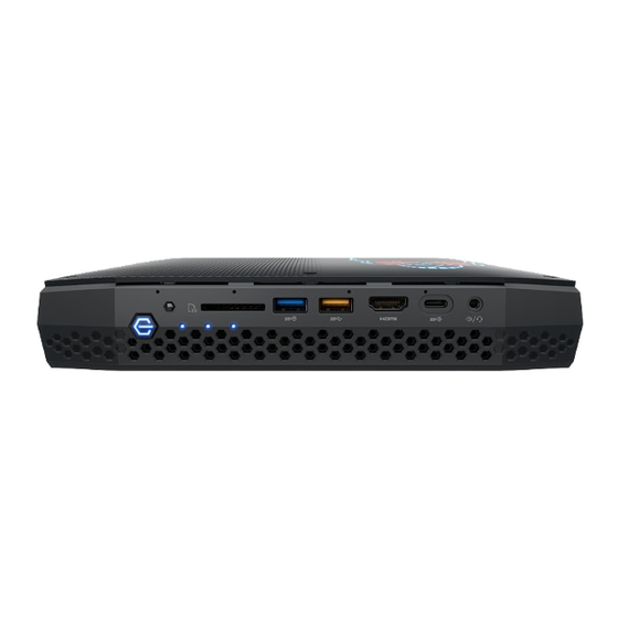
Page 34: Front Panel Connectors
• Top-Side headers and connectors 2.2.1 Front Panel Connectors Figure 6 shows the location of the components on the front of the Intel NUC Kit NUC8i7HN chassis. Figure 6. Front Panel Layout Table 10. Components Shown in Figure 6 Figure 6... - Page 35 Microsoft CIR specifications. Customers are required to provide their own media center compatible remote or smart phone application for use with the Intel NUC. The Location of the CIR is called out as Item B in Table 10 above.
-
Page 36: Back Panel Connectors
2.2.2 Back Panel Connectors Figure 7 shows the location of the components on the back of the Intel NUC Kit NUC8i7HN chassis. Figure 7. Back Panel Layout Table 11. Components Shown in Figure 7 Item from Figure 7 Description Speaker/SPDIF 19.5v DC power input jack... -
Page 37: Usb And I/O Headers
Technical Reference 2.2.3 USB and I/O Headers Figure 8 shows the location of the USB and I/O headers on the top-side of Intel NUC Kit NUC8i7HN. Figure 8. Headers and Connectors (Top) Table 12. Headers and Connectors Shown in Figure 8... -
Page 38: Figure 9. Usb 3.0 Internal Header (1.25 Mm Pitch)
2.2.3.1 Internal USB 3.0 Header (1.25 mm Pitch) Figure 9 is a connection diagram for internal USB .30 header. NOTE The +5 V DC power on the USB header is fused. • • Use only an internal USB connector that conforms to the USB 3.0 specification for high-speed USB devices. -
Page 39: Figure 10. Connection Diagram For The Internal Io Common Header (1.25 Mm Pitch)
Technical Reference 2.2.3.2 Internal Common IO Header (1.25 mm Pitch) Figure 10 is a connection diagram for internal Common IO header. NOTE The +5 V DC power on the USB header is fused. • • Use only an internal USB connector that conforms to the USB 2.0 specification for high-speed USB devices. -
Page 40: Figure 11. Additional Headers And Connectors
Figure 11 shows the location of all user addressable headers and connectors on the top-side of the Intel NUC Kit NUC8i7HN. Figure 11. Additional Headers and Connectors Table 13. Headers and Connectors Shown in Figure 11 Item from Figure 11... -
Page 41: Figure 12. Bios Security Jumper
Technical Reference 2.2.3.3 BIOS Security Jumper CAUTION Do not move a jumper with the power on. Always turn off the power and unplug the power cord from the computer before changing a jumper setting. Otherwise, the board could be damaged. Figure 12 shows the BIOS Security Jumper. -
Page 42: Table 14. Bios Security Jumper Settings
Table 14 lists the settings for the jumper. Table 14. BIOS Security Jumper Settings Function/Mode Jumper Setting Configuration Normal The BIOS uses current configuration information and passwords for booting. Lockdown The BIOS uses current configuration information and passwords for booting, except: •... - Page 43 Technical Reference continued Table 15. M.2 2280 Module (key type M) Connectors (continued) Signal Name Signal Name PEWAKE# (I/O)(0/3.3V) or N/C REFCLKP CLKREQ# (I/O)(0/3.3V) or N/C REFCLKN PERST# (O)(0/3.3V) or N/C PETp0/SATA-A+ PETn0/SATA-A- PERp0/SATA-B- PERn0/SATA-B+ DEVSLP (O) PETp1 PETn1 PERp1 PERn1 PETp2 PETn2...
-
Page 44: Figure 13. Kit Dimensions
2.2.3.5 Kit Dimensions Figure 13 illustrates the dimensions for the kit. Dimensions are given in millimeters. Figure 13. Kit Dimensions... -
Page 45: Vesa Bracket
Technical Reference VESA Bracket Figure 14 illustrates how to install the VESA mount bracket included with the kit. Figure 14. Install VESA Bracket... -
Page 46: Figure 15. Vesa Bracket Dimensions
Figure 15 shows the dimensions of the VESA bracket. Dimensions are given in millimeters. Figure 15. VESA Bracket Dimensions... -
Page 47: Power Supply
Technical Reference Power Supply The NUC8i7HN uses an AC to DC power adapter with a six foot attached cable with a barrel connector. Figure 16 shows the power adapter and plugs that may be included with the kit. • 100-240V AC Input 50-60 Hz 3.5 A •... -
Page 48: Power Supply Connector
The calculation is based on the Telcordia SR-332 Issue 2, Method I, Case 3, 55 ºC ambient. The MTBF prediction is used to estimate repair rates and spare parts requirements. The MTBF for Intel NUC8i7HN Kit is TBD Hours... -
Page 49: Environmental
Technical Reference Environmental Table 17 lists the environmental specifications for the kit. Table 17. Environmental Specifications Parameter Specification Temperature Non-Operating -40 °C to +60 °C Operating 0 °C to +40 °C The operating temperature of the kit may be determined by measuring the air temperature from the junction of the heatsink fins and fan, next to the attachment screw, in a closed chassis, while the system is in operation. -
Page 51: Overview Of Bios Features
Overview of BIOS Features Introduction The kit uses Intel® Visual BIOS that is stored in the Serial Peripheral Interface Flash Memory (SPI Flash) and can be updated using a disk-based program. The SPI Flash contains the Visual BIOS Setup program, POST, the PCI auto-configuration utility, LAN EEPROM information, and Plug and Play support. -
Page 52: Legacy Usb Support
BIOS configuration jumper. • Intel® Visual BIOS has an option to update the BIOS from a valid .bio file located on a hard disk or USB drive. Enter Intel Visual BIOS by pressing <F2> during POST. Using Front Panel menu option •... -
Page 53: Language Support
034499.htm 3.5.1 Language Support The BIOS Setup program and help messages are supported in US English. Check the Intel web site for support. BIOS Recovery It is unlikely that anything will interrupt a BIOS update; however, if an interruption occurs, the BIOS could be damaged. -
Page 54: Booting Without Attached Devices
Pressing the <F12> key during POST automatically forces booting from the LAN. To use this key during POST, the User Access Level in the BIOS Setup program's Security menu must be set to Full. 3.7.2 Booting Without Attached Devices For use in embedded applications, the BIOS has been designed so that after passing the POST, the operating system loader is invoked even if the following devices are not present: •... -
Page 55: Power Button Menu
At the point where Setup Entry/Boot would be in the normal boot path, the BIOS will display the following prompt and wait for a keystroke: [ESC] Normal Boot [F2] Intel Visual BIOS [F3] Disable Fast Boot [F4] BIOS Recovery [F7]... -
Page 56: Hard Disk Drive Password Security Feature
A manual power cycle will be required to resume system operation. NOTE As implemented on Intel NUC Kit NUC8i7HN, Hard Disk Drive Password Security is only supported on SATA port 0 (M.2 ). The passwords are stored on the hard disk drive so if the drive is relocated to another computer that does not support Hard Disk Drive Password Security feature, the drive will not be accessible. -
Page 57: Table 21. Supervisor And User Password Functions
Overview of BIOS Features The supervisor password gives unrestricted access to view and change all the Setup options • in the BIOS Setup program. This is the supervisor mode. • The user password gives restricted access to view and change Setup options in the BIOS Setup program. -
Page 58: System Led Functionality
Power Status, S0 and S3. S0 – Blue Solid, S3 – Blue Blinking Top Cover Eyes Power Status, S0 and S3. S0 – Blue Solid, S3 – Blue Blinking For more behaviors please download the Intel NUC LED Companion Application from https://downloadcenter.intel.com/download/27641... -
Page 59: Error Messages And Blink Codes
S3 Standby Blink primary color .25 seconds on, .25 seconds off, Default behavior; can be indefinitely. Indicates S3 state. changed via BIOS Setup Intel Ready Mode Solid secondary color Default behavior; can be changed via BIOS Setup BIOS update in progress Off when the update begins, then primary color on for 0.5 seconds, then off for 0.5 seconds.
Need help?
Do you have a question about the NUC8i7HN and is the answer not in the manual?
Questions and answers