Table of Contents
Advertisement
Quick Links
Intel® NUC Board
NUC5PGYH
Technical Product Specification
October 2016
Order Number: H78081-008
The Intel NUC Board NUC5PGYH may contain design defects or errors known as errata that may cause the product to deviate from published
specifications. Current characterized errata are documented in the Intel NUC Board NUC5PGYH Specification Update.
Advertisement
Table of Contents

Related Manuals for Intel NUC5PGYH


Summary of Contents for Intel NUC5PGYH
-
Page 1: Technical Product Specification
Order Number: H78081-008 The Intel NUC Board NUC5PGYH may contain design defects or errors known as errata that may cause the product to deviate from published specifications. Current characterized errata are documented in the Intel NUC Board NUC5PGYH Specification Update. -
Page 2: Revision History
® Processor Numbers Intel NUC Boards may contain design defects or errors known as errata, which may cause the product to deviate from published specifications. Current characterized errata are available on request. Contact your local Intel sales office or your distributor to obtain the latest specifications before placing your product order. -
Page 3: Board Identification Information
June 2016 Spec Clarification • Added 1.5.1.4 Analog Display (VGA) August 2016 Spec Change • Added information to section 1.5.1.1 Intel® High Definition (Intel® HD) Graphics • In Section 1.11.1 Hardware Monitoring, changed info to ITE IT8607D October 2016 Spec Change •... - Page 4 Intel NUC Board NUC5PGYH Technical Product Specification...
-
Page 5: Preface
NUC Board NUC5PGYH. Intended Audience The TPS is intended to provide detailed technical information about Intel NUC Board NUC5PGYH and its components to the vendors, system integrators, and other engineers and technicians who need this level of information. It is specifically not intended for general audiences. - Page 6 Intel NUC Board NUC5PGYH Technical Product Specification Other Common Notation Used after a signal name to identify an active-low signal (such as USBP0#) Gigabyte (1,073,741,824 bytes) GB/s Gigabytes per second Gb/s Gigabits per second Kilobyte (1024 bytes) Kilobit (1024 bits)
-
Page 7: Table Of Contents
Contents Revision History Board Identification Information ........................iii Errata ................................... iii Preface Intended Audience..............................v What This Document Contains ......................... v Typographical Conventions ..........................v Contents 1 Product Description Overview ..............................11 1.1.1 Feature Summary ........................11 1.1.2 Board Layout (Top) ....................... 13 1.1.3 Board Layout (Bottom) ...................... - Page 8 Intel NUC Board NUC5PGYH Technical Product Specification 1.12.1 ACPI ............................. 31 1.12.2 Hardware Support ......................... 33 2 Technical Reference Memory Resources ..........................37 2.1.1 Addressable Memory ......................37 Connectors and Headers ........................37 2.2.1 Front Panel Connectors ...................... 38 2.2.2 Back Panel Connectors .......................
- Page 9 Contents 5 Regulatory Compliance and Battery Disposal Information Regulatory Compliance ......................... 67 5.1.1 Safety Standards ........................67 5.1.2 European Union Declaration of Conformity Statement ........68 5.1.3 Product Ecology Statements .................... 69 5.1.4 EMC Regulations ........................69 5.1.5 e-Standby and ErP Compliance ..................73 5.1.6 Regulatory Compliance Marks (Board Level) .............
- Page 10 Intel NUC Board NUC5PGYH Technical Product Specification Wake-up Devices and Events ......................33 Headers and Connectors Shown in Figure 12 ................39 Connectors and Headers Shown in Figure 13 ................41 VGA Header ..............................42 SATA Power Header (1.25 mm Pitch) ....................42 Dual-Port Internal USB 2.0 Header (1.25 mm Pitch) ..............
-
Page 11: Product Description
• Support for up to 8 GB of system memory with one SO-DIMM using 4 Gb memory technology • Support for non-ECC memory • Support for 1.35 V low voltage JEDEC memory • Integrated graphics support with Intel ® Graphics Technology: Graphics ―... - Page 12 Intel NUC Board NUC5PGYH Technical Product Specification Table 1. Feature Summary (continued) Expansion Capabilities One M.2 Module supporting M.2 2230 cards (key type E) • Intel ® BIOS resident in the Serial Peripheral Interface (SPI) Flash device BIOS • Support for Advanced Configuration and Power Interface (ACPI), Plug and Play, and...
-
Page 13: Board Layout (Top)
Product Description 1.1.2 Board Layout (Top) Figure 1 shows the location of the major components on the top-side of Intel NUC Board NUC5PGYH. Figure 1. Major Board Components (Top) -
Page 14: Components Shown In Figure 1
Intel NUC Board NUC5PGYH Technical Product Specification Table 2 lists the components identified in Figure 1. Table 2. Components Shown in Figure 1 Item from Figure 1 Description Battery Front panel header Thermal solution Processor fan header Onboard power button... -
Page 15: Board Layout (Bottom)
Product Description 1.1.3 Board Layout (Bottom) Figure 2 shows the location of the major components on the bottom-side of Intel NUC Board NUC5PGYH. Figure 2. Major Board Components (Bottom) -
Page 16: Components Shown In Figure 2
Intel NUC Board NUC5PGYH Technical Product Specification Table 3. Components Shown in Figure 2 Item from Figure 2 Description Back panel connectors Auxiliary power connector (1.25 mm pitch) VGA connector M.2 2230 Module connector SDXC slot Front panel dual-port USB 2.0 header (1.25 mm pitch) SATA power connector (1.25 mm pitch) -
Page 17: Block Diagram
Product Description 1.1.4 Block Diagram Figure 3 is a block diagram of the major functional areas of the board. Figure 3. Block Diagram... -
Page 18: Online Support
Tested memory http://www.intel.com/NUCSupport Integration information http://www.intel.com/NUCSupport Processor Intel NUC Board NUC5PGYH has a soldered-down System-on-a-Chip (SoC), which consists of a quad-core Intel Pentium processor N3700 with up to 6 W TDP. • Integrated graphics Integrated memory controller • Integrated PCH •... -
Page 19: System Memory
8192 MB 4 Gbit 512 M x8/512 M x8 Note: “DS” refers to double-sided memory modules (containing two rows of SDRAM) and “SS” refers to single-sided memory modules (containing one row of SDRAM). For information about… Refer to: Tested Memory http://www.intel.com/NUCSupport... -
Page 20: Memory Channel And So-Dimm Configuration
Intel NUC Board NUC5PGYH Technical Product Specification Figure 4 illustrates the memory channel and SO-DIMM configuration. Figure 4. Memory Channel and SO-DIMM Configuration... -
Page 21: Processor Graphics Subsystem
Product Description Processor Graphics Subsystem The board supports graphics through Intel HD Graphics. 1.5.1 Integrated Graphics The board supports integrated graphics via the processor. 1.5.1.1 Intel ® High Definition (Intel ® HD) Graphics The Intel HD graphics controller features the following: •... - Page 22 Intel NUC Board NUC5PGYH Technical Product Specification 1.5.1.4 Analog Display (VGA) The VGA port supports analog displays. The maximum supported resolution is 1920 x 1200 (WUXGA) at a 60 Hz refresh rate. LPCM, 192 kHz/24-bit, 8 Channel •...
-
Page 23: Usb
In order to use AHCI mode, AHCI must be enabled in the BIOS. Microsoft* Windows 8 includes the necessary AHCI drivers without the need to install separate AHCI drivers during the operating system installation process. However, it is always good practice to update the AHCI drivers to the latest available by Intel. -
Page 24: Real-Time Clock Subsystem
Intel NUC Board NUC5PGYH Technical Product Specification Real-Time Clock Subsystem A coin-cell battery (CR2032) powers the real-time clock and CMOS memory. When the computer is not plugged into a wall socket, the battery has an estimated life of three years. When the computer is plugged in, the standby current from the power supply extends the life of the battery. -
Page 25: Audio Subsystem
Product Description Audio Subsystem The board supports Intel HD Audio via the Realtek ALC283 audio codec. The audio subsystem supports the following features: Analog line-out/Analog Headphone/Analog Microphone jack on the front panel • • High Definition Audio via a stereo microphone/headphone jack on the back panel •... -
Page 26: Mini-Toslink Interface
Mini-TOSLINK adaptor necessary to connect to standard TOSLINK cable Stereo audio out Figure 6. Mini-TOSLINK Adaptor 1.9.2 Audio Subsystem Software Audio software and drivers are available from Intel’s World Wide Web site. For information about Refer to Obtaining Audio software and drivers http://downloadcenter.intel.com... -
Page 27: Lan Subsystem
Full device driver compatibility • For information about Refer to Full LAN Hardware feature set http://www.realtek.com.tw/ 1.10.2 LAN Subsystem Software LAN software and drivers are available from Intel’s World Wide Web site. For information about Refer to Obtaining LAN software and drivers http://downloadcenter.intel.com... -
Page 28: Rj-45 Lan Connector With Integrated Leds
100 Mb/s data rate is selected. Yellow 1000 Mb/s data rate is selected. 1.10.4 Wireless Network Module The Intel Dual Band Wireless-AC 3165 module provides hi-speed wireless connectivity with the following capabilities: • Intel® Dual Band Wireless-AC 3165 module •... -
Page 29: Hardware Management Subsystem
Management (WfM) specification. The board has several hardware management features, including thermal and voltage monitoring. For information about Refer to Wired for Management (WfM) Specification www.intel.com/design/archives/wfm/ 1.11.1 Hardware Monitoring The hardware monitoring and fan control subsystem is based on an ITE IT8607D embedded controller, which supports the following: •... -
Page 30: Thermal Solution
Intel NUC Board NUC5PGYH Technical Product Specification 1.11.3 Thermal Solution Figure 8 shows the location of the thermal solution and processor fan header. Item Description Processor fan header Thermal solution Figure 8. Thermal Solution and Fan Header... -
Page 31: Power Management
Product Description 1.12 Power Management Power management is implemented at several levels, including: • Software support through Advanced Configuration and Power Interface (ACPI) Hardware support: • Power Input Instantly Available PC technology LAN wake capabilities Wake from USB ... -
Page 32: Power States And Targeted System Power
Intel NUC Board NUC5PGYH Technical Product Specification 1.12.1.1 System States and Power States Under ACPI, the operating system directs all system and device power state transitions. The operating system puts devices in and out of low-power states based on user preferences and knowledge of how devices are being used by applications. -
Page 33: Hardware Support
Product Description 1.12.1.2 Wake-up Devices and Events Table 8 lists the devices or specific events that can wake the computer from specific states. Table 8. Wake-up Devices and Events Devices/events that wake up the system… …from this sleep state Comments Power switch S3, S4, S5 (Note 1) -
Page 34: Power Input
Intel NUC Board NUC5PGYH Technical Product Specification 1.12.2.1 Power Input When resuming from an AC power failure, the computer may return to the power state it was in before power was interrupted (on or off). The computer’s response can be set using the Last Power State feature in the BIOS Setup program’s Boot menu. -
Page 35: Location Of The Standby Power Led
Product Description 1.12.2.8 +5 V Standby Power Indicator LED The standby power indicator LED shows that power is still present even when the computer appears to be off. Figure 9 shows the location of the standby power LED. CAUTION If AC power has been switched off and the standby power indicator is still lit, disconnect the power cord before installing or removing any devices connected to the board. -
Page 37: Technical Reference
Technical Reference Memory Resources 2.1.1 Addressable Memory The board utilizes up to 8 GB of addressable system memory. Typically the address space that is allocated for PCI Conventional bus add-in cards, PCI Express configuration space, BIOS (SPI Flash device), and chipset overhead resides above the top of DRAM (total system memory). On a system that has 8 GB of system memory installed, it is not possible to use all of the installed memory due to system address space being allocated for other system critical functions. -
Page 38: Front Panel Connectors
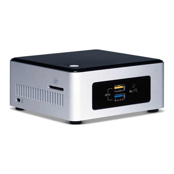
Intel NUC Board NUC5PGYH Technical Product Specification 2.2.1 Front Panel Connectors Figure 10 shows the location of the front panel connectors for the board. Item Description Front panel Stereo microphone/headphone jack USB 3.0 ports (one blue and one orange charging capable) Figure 10. -
Page 39: Headers And Connectors (Top)
Technical Reference 2.2.3 Headers and Connectors (Top) Figure 12 shows the location of the headers and connectors on the top-side of the board. Figure 12. Headers and Connectors (Top) Table 9 lists the headers and connectors identified in Figure 12. Table 9. -
Page 40: Connectors And Headers (Bottom)
Intel NUC Board NUC5PGYH Technical Product Specification 2.2.4 Connectors and Headers (Bottom) Figure 13 shows the locations of the connectors and headers on the bottom-side of the board. Figure 13. Connectors and Headers (Bottom) -
Page 41: Connectors And Headers Shown In Figure 13
Technical Reference Table 10 lists the connectors and headers identified in Figure 13. Table 10. Connectors and Headers Shown in Figure 13 Item from Figure 13 Description Auxiliary power connector (1.25 mm pitch) VGA connector M.2 2230 Module connector SDXC slot Front panel dual-port USB 2.0 header (1.25 mm pitch) SATA power connector (1.25 mm pitch) SATA 6.0 Gb/s connector... -
Page 42: Vga Header
Intel NUC Board NUC5PGYH Technical Product Specification 2.2.4.1 Signal Tables for the Connectors and Headers Table 11. VGA Header Signal Name Signal Name DATA VSYNC HSYNC GREEN BLUE Table 12. SATA Power Header (1.25 mm Pitch) Signal Name 3.3 V NOTE Connector is Molex* part number 53398-0571, 1.25 mm pitch PicoBlade* header, surface mount,... -
Page 43: M.2 2230 Module (Mechanical Key E) Connector
Technical Reference Table 14. M.2 2230 Module (Mechanical Key E) Connector Signal Name Signal Name 3.3V 3.3V RESERVED RESERVED RESERVED RESERVED RESERVED RESERVED RESERVED RESERVED ALERT# (I)(0/3.3) I2C CLK (O)(0/3.3) RESERVED I2C DATA (I/O)(0/3.3) RESERVED W_DISABLE1# (O)(0/3.3V) W_DISABLE2# (O)(0/3.3V) PEWAKE0# (I/O)(0/3.3V) PERST0# (O)(0/3.3V) CLKREQ0# (I/O)(0/3.3V) SUSCLK(32kHz) (O)(0/3.3V) -
Page 44: Sdxc Card Reader Connector
Intel NUC Board NUC5PGYH Technical Product Specification 2.2.4.2 Add-in Card Connector The board supports a M.2 2230 (key type E) module. • Supports M.2 communication module 2.2.4.3 SDXC Card Reader The board has a standard Secure Digital (SD) card reader that supports the Secure Digital eXtended Capacity (SDXC) format, 3.01 specification with UHS-I support. -
Page 45: Auxiliary Power Connector
Technical Reference 2.2.4.4 Power Supply Connector The board has the following power supply connector: External Power Supply – the board can be powered through a 12-19 V DC connector on the • back panel. The back panel DC connector is compatible with a 5.5 mm/OD (outer diameter) and 2.5 mm/ID (inner diameter) plug, where the inner contact is +12 (±10%) V DC and the shell is GND. -
Page 46: Connection Diagram For Front Panel Header (2.0 Mm Pitch)
Intel NUC Board NUC5PGYH Technical Product Specification 2.2.4.5 Front Panel Header (2.0 mm Pitch) This section describes the functions of the front panel header. Table 17 lists the signal names of the front panel header. Figure 14 is a connection diagram for the front panel header. -
Page 47: States For A One-Color Power Led
Technical Reference 2.2.4.5.3 Power/Sleep LED Header Pins 2 and 4 can be connected to a one- or two-color LED. Table 18 and Table 19 show the possible LED states. Table 18. States for a One-Color Power LED LED State Description Power off Blinking Standby... -
Page 48: Location Of The Cir Sensor
Microsoft CIR specifications. Customers are required to provide their own media center compatible remote or smart phone application for use with the Intel NUC. Figure 15 shows the location of the CIR sensor. Item Description CIR Sensor Figure 15. -
Page 49: Connection Diagram For Internal Usb 2.0 Dual-Port Header (1.25 Mm Pitch)
Technical Reference 2.2.4.7 Internal USB 2.0 Dual-Port Header (1.25 mm Pitch) Figure 16 is a connection diagram for the internal USB header. Connector is Molex part number 53398-0571, 1.25 mm pitch PicoBlade header, surface mount, vertical, lead-free, 8 circuits. NOTE The +5 V DC power on the USB header is fused. -
Page 50: Bios Security Jumper
Intel NUC Board NUC5PGYH Technical Product Specification BIOS Security Jumper CAUTION Do not move a jumper with the power on. Always turn off the power and unplug the power cord from the computer before changing a jumper setting. Otherwise, the board could be damaged. -
Page 51: Bios Security Jumper Settings
Technical Reference Table 20 lists the settings for the jumper. Table 20. BIOS Security Jumper Settings Function/Mode Jumper Setting Configuration Normal The BIOS uses current configuration information and passwords for booting. Lockdown The BIOS uses current configuration information and passwords for booting, except: •... -
Page 52: Mechanical Considerations
Intel NUC Board NUC5PGYH Technical Product Specification Mechanical Considerations 2.4.1 Form Factor The board is designed to fit into a custom chassis. Figure 18 illustrates the mechanical form factor for the board. Dimensions are given in millimeters. The outer dimensions are 101.60 millimeters by 101.60 millimeters [4.0 inches by 4.0 inches]. -
Page 53: Electrical Considerations
All responsibility for determining the adequacy of any thermal or system design remains solely with the system integrator. Intel makes no warranties or representations that merely following the instructions presented in this document will result in a system with adequate thermal performance. -
Page 54: Localized High Temperature Zones
Intel NUC Board NUC5PGYH Technical Product Specification CAUTION Ensure that the ambient temperature does not exceed the board’s maximum operating temperature. Failure to do so could cause components to exceed their maximum case temperature and malfunction. For information about the maximum operating temperature, see the environmental specifications in Section 2.8. -
Page 55: Thermal Considerations For Components
Technical Reference Table 22 provides maximum case temperatures for the components that are sensitive to thermal changes. The operating temperature, current load, or operating frequency could affect case temperatures. Maximum case temperatures are important when considering proper airflow to cool the board. Table 22. -
Page 56: Reliability
Intel NUC Board NUC5PGYH Technical Product Specification Reliability The Mean Time Between Failures (MTBF) prediction is calculated using component and subassembly random failure rates. The calculation is based on the Telcordia SR-332-2 Issue 2, Method I, Case 3, 55 ºC ambient. The MTBF prediction is used to estimate repair rates and spare parts requirements. -
Page 57: Overview Of Bios Features
Overview of BIOS Features Introduction The board uses an Intel Visual BIOS that is stored in the Serial Peripheral Interface Flash Memory (SPI Flash) and can be updated using a disk-based program. The SPI Flash contains the Visual BIOS Setup program, POST, the PCI auto-configuration utility, LAN EEPROM information, and Plug and Play support. -
Page 58: Legacy Usb Support
BIOS can be updated from a file on a hard disk, a USB drive (a flash drive or a USB hard drive), or a CD-ROM. Intel F7 switch during POST allows a user to select where the BIOS .bio file is located and •... -
Page 59: Language Support
BIOS update utilities http://www.intel.com/support/motherboards/desktop/sb/CS- 034499.htm 3.5.1 Language Support The BIOS Setup program and help messages are supported in US English. Check the Intel web site for support. 3.5.2 Custom Splash Screen During POST, an Intel splash screen is displayed by default. This splash screen can be ®... -
Page 60: Bios Recovery
Intel NUC Board NUC5PGYH Technical Product Specification BIOS Recovery It is unlikely that anything will interrupt a BIOS update; however, if an interruption occurs, the BIOS could be damaged. Table 25 lists the drives and media types that can and cannot be used for BIOS recovery. -
Page 61: Boot Options
Overview of BIOS Features Boot Options In the BIOS Setup program, the user can choose to boot from a hard drive, optical drive, removable drive, or the network. The default setting is for the optical drive to be the first boot device, the hard drive second, removable drive third, and the network fourth. -
Page 62: Power Button Menu
Intel NUC Board NUC5PGYH Technical Product Specification 3.7.4 Power Button Menu The Power Button Menu is accessible via the following sequence: 1. System is in S4/S5 (not G3) 2. User pushes the power button and holds it down 3. The system will emit three short beeps from the PC speaker or headphones, if installed, then stop to signal the user to release the power button (approximately 3 seconds) or the power button LED to its alternate color. -
Page 63: Hard Disk Drive Password Security Feature
Overview of BIOS Features Hard Disk Drive Password Security Feature The Hard Disk Drive Password Security feature blocks read and write accesses to the hard disk drive until the correct password is given. Hard Disk Drive Passwords are set in BIOS SETUP and are prompted for during BIOS POST. -
Page 64: Bios Security Features
Intel NUC Board NUC5PGYH Technical Product Specification BIOS Security Features The BIOS includes security features that restrict access to the BIOS Setup program and who can boot the computer. A supervisor password and a user password can be set for the BIOS Setup... -
Page 65: Error Messages And Blink Codes
Error Messages and Blink Codes Front-panel Power LED Blink Codes Whenever a recoverable error occurs during POST, the BIOS causes the board’s front panel power LED to blink an error message describing the problem (see Table 29). Table 29. Front-panel Power LED Blink Codes Type Pattern Note... - Page 66 Intel NUC Board NUC5PGYH Technical Product Specification...
-
Page 67: Regulatory Compliance And Battery Disposal Information
Electromagnetic Compatibility (EMC) standards • Product certification markings 5.1.1 Safety Standards Intel NUC Board NUC5PGYH complies with the safety standards stated in Table 31 when correctly installed in a compatible host system. Table 31. Safety Standards Standard Title CSA/UL 60950-1 Information Technology Equipment –... -
Page 68: European Union Declaration Of Conformity Statement
5.1.2 European Union Declaration of Conformity Statement We, Intel Corporation, declare under our sole responsibility that the product Intel NUC Board NUC5PGYH is in conformity with all applicable essential requirements necessary for CE marking, following the provisions of the European Council Directive 2004/108/EC (EMC Directive), 2006/95/EC (Low Voltage Directive), and 2002/95/EC (ROHS Directive). -
Page 69: Product Ecology Statements
This product contains the following materials that may be regulated upon disposal: lead solder on the printed wiring board assembly. 5.1.4 EMC Regulations Intel NUC Board NUC5PGYH complies with the EMC regulations stated in Table 32 when correctly installed in a compatible host system. Table 32. EMC Regulations Regulation... - Page 70 Intel NUC Board NUC5PGYH Technical Product Specification...
- Page 71 • Consult the dealer or an experienced radio/TV technician for help. Any changes or modifications to the equipment not expressly approved by Intel Corporation could void the user’s authority to operate the equipment. Tested to comply with FCC standards for home or office use.
- Page 72 Intel NUC Board NUC5PGYH Technical Product Specification Japan VCCI Statement Japan VCCI Statement translation: This is a Class B product based on the standard of the Voluntary Control Council for Interference from Information Technology Equipment (VCCI). If this is used near a radio or television receiver in a domestic environment, it may cause radio interference.
-
Page 73: E-Standby And Erp Compliance
Regulatory Compliance and Battery Disposal Information 5.1.5 e-Standby and ErP Compliance Intel NUC Board NUC5PGYH meets the following program requirements in an adequate system configuration, including appropriate selection of an efficient power supply: • EPEAT* Korea e-Standby • European Union Energy-related Products Directive 2013 (ErP) Lot 6 •... -
Page 74: Regulatory Compliance Marks (Board Level)
(solder side). China RoHS/Environmentally Friendly Use Period Logo: This is an example of the symbol used on Intel NUC Boards and associated collateral. The color of the mark may vary depending upon the application. The Environmental Friendly Usage Period (EFUP) -
Page 75: Battery Disposal Information
Regulatory Compliance and Battery Disposal Information Battery Disposal Information CAUTION Risk of explosion if the battery is replaced with an incorrect type. Batteries should be recycled where possible. Disposal of used batteries must be in accordance with local environmental regulations. PRÉCAUTION Risque d'explosion si la pile usagée est remplacée par une pile de type incorrect. - Page 76 Intel NUC Board NUC5PGYH Technical Product Specification PRECAUCIÓN Existe peligro de explosión si la pila no se cambia de forma adecuada. Utilice solamente pilas iguales o del mismo tipo que las recomendadas por el fabricante del equipo. Para deshacerse de las pilas usadas, siga igualmente las instrucciones del fabricante.
- Page 77 Regulatory Compliance and Battery Disposal Information AWAS Risiko letupan wujud jika bateri digantikan dengan jenis yang tidak betul. Bateri sepatutnya dikitar semula jika boleh. Pelupusan bateri terpakai mestilah mematuhi peraturan alam sekitar tempatan. OSTRZEŻENIE Istnieje niebezpieczeństwo wybuchu w przypadku zastosowania niewłaściwego typu baterii. Zużyte baterie należy w miarę...
- Page 78 Intel NUC Board NUC5PGYH Technical Product Specification...
- Page 79 Regulatory Compliance and Battery Disposal Information...
Need help?
Do you have a question about the NUC5PGYH and is the answer not in the manual?
Questions and answers