
Subscribe to Our Youtube Channel
Related Manuals for BONFIGLIOLI ACTIVE CUBE 201


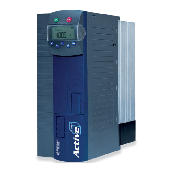
Summary of Contents for BONFIGLIOLI ACTIVE CUBE 201
- Page 1 ACTIVE CUBE Operating Instructions Frequency inverter 230 V / 400 V 0.25 kW ... 132 kW...
-
Page 3: Table Of Contents
TABLE OF CONTENTS General Information about the Documentation ............11 Instruction Manuals ..................11 This document ....................12 Warranty and liability ..................13 Obligation ......................13 Copyright ......................14 Storage ......................14 General safety instructions and information on use ............ 15 Terminology ...................... - Page 4 Transfer to place of installation ............... 25 Unpacking the device ..................25 Bringing the device into installation position ..........25 3.6.1 Sizes 1 through 6 ..................... 25 3.6.2 Sizes 7 and 8 ......................25 Scope of supply ......................27 Sizes 1 and 2: ACU 201 (up to 3.0 kW) and 401 (up to 4.0 kW) ...... 27 Sizes 3 and 4: ACU 201 (4.0 to 9.2 kW) and 401 (5.5 to 15.0 kW) ....
- Page 5 7.4.3.1 Length of motor cables, without filter..............61 7.4.3.2 Motor cable length, with output filter dU/dt ............61 7.4.3.3 Motor cable length, with sinus filter ..............61 7.4.3.4 Group drive .......................61 7.4.3.5 Speed sensor connection ..................61 7.4.4 Connection of a braking resistor ................62 Connection by size ....................
- Page 6 8.6.1 Activation ......................... 94 8.6.2 Data transfer ......................95 8.6.3 Resetting to Normal Operation .................. 96 Control Menu (CTRL) ..................96 Controlling the Motor via the Control Unit ............97 Commissioning of frequency inverter ................99 Turn mains voltage on ..................99 Setup Using the Control Unit ................
- Page 7 11.2.7 Peak current ......................125 11.2.8 Reverse sense of rotation ..................125 11.3 Internal values ....................125 11.4 Speed Sensor 1 ....................126 11.4.1 Operation Mode Speed Sensor 1 ................126 11.4.2 Division Marks, Speed Sensor 1 ................128 11.4.3 Gear factor speed sensor 1 ..................128 11.4.4 Filter time constant, Speed Sensor 1 .................
- Page 8 15.4.1 Block diagram ......................154 15.5 Reference percentage channel ............... 156 15.5.1 Block diagram ......................157 15.6 Fixed reference values ................... 159 15.6.1 Fixed frequencies ....................159 15.6.2 JOG frequency ......................159 15.6.3 Fixed percentages ....................160 15.7 Frequency ramps .................... 160 15.8 Percentage Value Ramps ................
- Page 9 16.5 Function Modules ................... 195 16.5.1 Timer ........................195 16.5.1.1 Timer – Time Constant ..................196 16.5.2 Comparator ......................198 16.5.3 Table of functions ....................200 16.5.4 Multiplexer/demultiplexer ..................200 17 V/f characteristic ....................... 202 17.1 Dynamic voltage pre-control ................203 18 Control functions ......................
- Page 10 20 Actual values ......................251 20.1 Actual values of frequency inverter ............... 251 20.1.1 STO Status ......................253 20.2 Actual values of machine................253 20.3 Actual value memory ..................254 20.4 Actual values of the system ................255 20.4.1 Actual value system ....................255 20.4.2 Volumetric Flow and Pressure...................
-
Page 11: General Information About The Documentation
Information on various subjects connected with the use of the frequency inverter is described specific to the application. If you need a copy of the documentation or additional information, contact your local representative of BONFIGLIOLI. ACTIVE CUBE The following instructions are available for the... -
Page 12: This Document
Neither was it possible to consider all conceivable installation, operation or maintenance situations. If you require further information or if you encounter specific problems which are not dealt with in sufficient detail in the documentation, contact your local BONFIGLIOLI agent. -
Page 13: Warranty And Liability
Figure 1-1: Device identification Warranty and liability BONFIGLIOLI VECTRON GmbH (hereinafter referred to as “manufacturer”) notes that the contents of this Operating Instructions document do not form part of any previous or existing agreement, assurance or legal relationship between the manufacturer and the user of these Operating Instructions (hereinafter referred to as the “User”). -
Page 14: Copyright
Copyright Any copyrights relating to this document shall remain with BONFIGLIOLI VECTRON GmbH Europark Fichtenhain B6 47807 Krefeld Germany This document is intended for the operator of the frequency inverter. Any disclosure or copying of this document, exploitation and communication of its contents (as hardcopy or electronically) shall be forbidden, unless permitted expressly. -
Page 15: General Safety Instructions And Information On Use
General safety instructions and information on use The chapter "General safety instructions and information on use" contains general safety instructions for the Operator and the Operating Staff. At the beginning of certain main chapters, some safety instructions are included which apply to all work described in the relevant chapter. Special work- specific safety instructions are provided before each safety-relevant work step. -
Page 16: Misuse
The technical data, connection specifications and information on ambient conditions are indicated on the rating plate and in the documentation and must be complied with in any case. Misuse Any use other than that described in "Designated use" shall not be permissible and shall be considered as misuse. -
Page 17: Warning Information And Symbols Used In The Operating Instructions
Warning information and symbols used in the Operating Instructions 2.6.1 Hazard classes The following hazard identifications and symbols are used in the Operating Instructions to mark particularly important information: DANGER Identification of immediate threat holding a high risk of death or serious injury if not avoided. -
Page 18: Personal Safety Equipment
2.6.4 Personal safety equipment Symbol Meaning Wear body protection Wear ear protectors 2.6.5 Recycling Symbol Meaning Recycling, to avoid waste, collect all materials for reuse 2.6.6 Grounding symbol Symbol Meaning Ground connection 2.6.7 ESD symbol Symbol Meaning ESD: Electrostatic Sensitive Devices, i.e. -
Page 19: Directives And Guidelines To Be Adhered To By The Operator
Directives and guidelines to be adhered to by the operator The operator must follow the following directives and regulations: Ensure that the applicable workplace-related accident prevention regulations as well as other applicable national regulation are accessible to the staff. ... -
Page 20: Organizational Measures
2.10.2 Use in combination with third-party products Please note that Bonfiglioli Vectron MDS GmbH will not accept any responsibility for compatibility with third-party products (e.g. motors, cables or filters).. In order to enable optimum system compatibility Bonfiglioli Vectron MDS GmbH offers components facilitating commissioning and providing optimum synchronization of the machine/plant parts in operation. -
Page 21: Safe Operation
2.10.5 Safe operation During operation of the frequency inverter, always comply with the applicable national and international regulations/laws on work on electrical equipment/plants. Before commissioning and the start of the operation, make sure to fix all covers and check the terminals. -
Page 22: Maintenance And Service/Troubleshooting
2.10.6 Maintenance and service/troubleshooting Visually inspect the frequency inverter when carrying out the required maintenance work and inspections at the machine/plant. Perform the maintenance work and inspections prescribed for the machine carefully, including the specifications on parts/equipment replacement. ... -
Page 23: Safety Instructions On Function "Safe Torque Off" (Sto)
STO, access to the hazard areas must be prevented until the drive has stopped. Check the safety function at regular intervals according to the results of your risk analysis. Bonfiglioli Vectron MDS GmbH recommends that the check be performed after one year, at the latest. -
Page 24: Storage And Transport
Storage and transport NOTICE Draining the heat sink Liquid cooled devices may be transported only with the heat sink completely drained of the coolant. Use compressed air to drain the heat sink radiator. Storage NOTICE Damage caused by incorrect storage ... -
Page 25: Dimensions/Weight
Dimensions/weight For information on the weight and dimensions of the frequency inverter, refer to chapter 5 “Technical data”. Transfer to place of installation Transfer to the place of installation is done with the product in its original packaging. Frequency inverters as from size 7 must be transferred to the place of installation in horizontal position, rear-side down. - Page 26 NOTICE The pull angle must not be smaller than 60°. Use appropriate lifting means and a crane to lift the frequency inverter up carefully. Bring the device into vertical position by turning it up on the pallet via the rear lower edge of the case. NOTICE Do not leave the device standing in upright position.
-
Page 27: Scope Of Supply
4 Scope of supply Due to modular hardware components, the frequency inverters can be integrated in the automation concept easily. The scope of delivery described can be supplemented by optional components and adapted to the customer-specific requirements. The plug-in type connection terminals enable a safe function and quick and easy assembly. -
Page 28: Sizes 3 And 4: Acu 201 (4.0 To 9.2 Kw) And 401 (5.5 To 15.0 Kw)
Sizes 3 and 4: ACU 201 (4.0 to 9.2 kW) and 401 (5.5 to 15.0 kW) Scope of supply Scope of supply Frequency inverter Terminal strip X10 (Phoenix ZEC 1.5/3ST5.0) Plug-in terminals for the relay output Standard fittings with fitting screws (M4x20, M4x60) for vertical assembly Quick Start Guide and Operating Instructions Control terminals X210A / X210B (Wieland DST85 / RM3.5) -
Page 29: Size 5 Acu 401 (18.5 To 30.0 Kw)
Size 5 ACU 401 (18.5 to 30.0 kW) Scope of supply Scope of supply Frequency inverter Terminal strip X10 (Phoenix ZEC 1.5/3ST5.0) Plug-in terminals for the relay output Standard fittings with fitting screws (M4x20, M4x70) for vertical assembly Quick Start Guide and Operating Instructions Control terminals X210A / X210B (Wieland DST85 / RM3.5) Plug-in terminal for connection of the control signals Please check incoming goods for quality, quantity and nature without delay. -
Page 30: Size 6 Acu 401 (37.0 To 65.0 Kw)
Size 6 ACU 401 (37.0 to 65.0 kW) Scope of supply Scope of supply Frequency inverter The illustration shows an air-cooled frequency inverter as an example. Terminal strip X10 (Phoenix ZEC 1.5/3ST5.0) Plug-in terminals for the relay output For air-cooled frequency inverters only: Standard fittings with fitting screws (M5x20) for vertical assembly Quick Start Guide and Operating Instructions Control terminals X210A / X210B (Wieland DST85 / RM3.5) -
Page 31: Size 7 Acu 401 (75.0 To 132.0 Kw)
Size 7 ACU 401 (75.0 to 132.0 kW) Scope of supply Scope of supply Frequency inverter The illustration shows an air-cooled frequency inverter as an example. Terminal strip X10 (Phoenix ZEC 1.5/3ST5.0) Plug-in terminals for the relay output Control terminals X210A / X210B (Wieland DST85 / RM3.5) Plug-in terminal for connection of the control signals Quick Start Guide and Operating Instructions Please check incoming goods for quality, quantity and nature without delay. -
Page 32: Technical Data
5 Technical data General technical data CE conformity The ACU frequency inverters meet the requirements of the low voltage directive 2006/95/EEC and DIN EN 61800-5-1. EMC directive For proper installation of the frequency inverter in order to meet the requirements of EN 61800-3, please comply with the installation instructions in these operating instructions. -
Page 33: Technical Data - Control Electronic Equipment
Max. permissible Up to 132 kW device power (size 7): 5 kA short-circuit current to be expected with mains supply Contamination The frequency inverters are designed for Pollution Degree 2. level Overvoltage The frequency inverters are designed for Overvoltage Category III. category Functions ... - Page 34 By default, the different configurations occupy the control terminals with certain settings. These settings can be adjusted to the specific application, and various functions can be assigned freely to the control terminals. For an overview of the settings, see Page 282 of these Operating Instructions. Technical data of control terminals Digital inputs (X210A.3…X210B.2): ...
-
Page 35: Acu 201 Size 1 (0.25 To 1.1 Kw, 230 V)
ACU 201 Size 1 (0.25 to 1.1 kw, 230 V) Type ACU 201 Size Output, motor side Recommended motor shaft power 0.25 0.37 0.55 0.75 Output current Long-term overload current (60 s) Short-time overload current (1 s) Output voltage Maximum input voltage, three-phase Protection Short circuit / earth fault proof Rotary field frequency... -
Page 36: Acu 201 Size 2 (1.5 To 3.0 Kw, 230 V)
ACU 201 Size 2 (1.5 to 3.0 kW, 230 V) Type ACU 201 Size Output, motor side Recommended motor shaft power 4) 5) Output current 12.5 Long-term overload current (60 s) 10.5 14.3 16.2 Short-time overload current (1 s) 14.0 19.0 19.0 Output voltage... -
Page 37: Acu 201 Sizes 3 And 4 (4.0 To 9.2 Kw, 230 V)
ACU 201 sizes 3 and 4 (4.0 to 9.2 kW, 230 V) Type ACU 201 Size Output, motor side Recommended motor shaft power Output current 18.0 22.0 32.0 35.0 Long-term overload current (60 s) 26.3 30.3 44.5 51.5 Short-time overload current (1 s) 33.0 33.0 64.0... -
Page 38: Acu 401 Size 1 (0.25 To 1.5 Kw, 400 V)
ACU 401 Size 1 (0.25 to 1.5 kW, 400 V) Type ACU 401 Size Output, motor side Recommended motor shaft power 0.25 0.37 0.55 0.75 Output current Long-term overload current (60 s) Short-time overload current (1 s) Output voltage Maximum input voltage, three-phase Protection Short circuit / earth fault proof Rotary field frequency... -
Page 39: Acu 401 Size 2 (1.85 To 4.0 Kw, 400 V)
ACU 401 Size 2 (1.85 to 4.0 kW, 400 V) Type ACU 401 Size Output, motor side Recommended motor shaft power 1.85 Output current Long-term overload current (60 s) 11.7 13.5 Short-time overload current (1 s) 11.6 15.6 18.0 Output voltage Maximum input voltage, three-phase Protection Short circuit / earth fault proof... -
Page 40: Acu 401 Sizes 3 And 4 (5.5 To 15.0 Kw, 400 V)
ACU 401 sizes 3 and 4 (5.5 to 15.0 kW, 400 V) Type ACU 401 Size Output, motor side Recommended motor shaft power 11.0 15.0 Output current 14.0 18.0 25.0 32.0 22.0 Long-term overload current (60 s) 21.0 26.3 30.3 37.5 44.5 Short-time overload current (1 s) -
Page 41: Acu 401 Size 5 (18.5 To 30.0 Kw, 400 V)
ACU 401 Size 5 (18.5 to 30.0 kW, 400 V) Type ACU 401 Size Output, motor side Recommended motor shaft power 18.5 22.0 30.0 Output current 40.0 45.0 60.0 Long-term overload current (60 s) 60.0 67.5 90.0 Short-time overload current (1 s) 80.0 90.0 120.0... -
Page 42: Acu 401 Size 6 (37.0 To 65.0 Kw, 400 V)
5.10 ACU 401 Size 6 (37.0 to 65.0 kW, 400 V) Type ACU 401 Size Output, motor side Recommended motor shaft power 37.0 45.0 55.0 65.0 Output current 75.0 90.0 110.0 125.0 Long-term overload current (60 s) 112.5 135.0 165.0 187.5 Short-time overload current (1 s) 150.0... -
Page 43: Acu 401 Size 7 (75.0 To 132.0 Kw, 400 V)
5.11 ACU 401 Size 7 (75.0 to 132.0 kW, 400 V) Type ACU 401 Size Output, motor side Recommended motor shaft power Output current Long-term overload current (60 s) Short-time overload current (1 s) Output voltage Maximum input voltage, three-phase Protection Short circuit / earth fault proof Rotary field frequency... -
Page 44: Operation Diagrams
5.12 Operation diagrams The technical data of the frequency inverters refer to the nominal point which was selected to enable a wide range of applications. A functionally and efficient dimensioning (derating) of the frequency inverters is possible based on the following diagrams. Installation height Power reduction (Derating), max. - Page 45 12/16 Operating Instructions ACU...
-
Page 46: Mechanical Installation
6 Mechanical installation As a standard, the frequency inverters of ingress protection rating IP20 are designed for stationary installation in electrical cabinets. Apart from the air-cooled standard installation variant described in these Operating Instructions other installation variants are available: Feedthrough assembly for sizes 1 through 8, see "Installation Instructions –... - Page 47 Standard installation 100 mm For assembly the long side of the fixing plate is inserted in the heat sink and screwed to the assembly panel. The dimensions of the device and the installation dimensions are those of the standard device without optional components and are given in millimeters.
-
Page 48: Sizes 3 And 4: Acu 201 (4.0 To 9.2 Kw) And 401 (5.5 To 15.0 Kw)
Sizes 3 and 4: ACU 201 (4.0 to 9.2 kW) and 401 (5.5 to 15.0 kW) The frequency inverter is mounted in a vertical position on the assembly panel by means of the standard fittings. The following illustration shows the standard fitting. Standard installation ... -
Page 49: Size 5: Acu 401 (18.5 To 30.0 Kw)
Size 5: ACU 401 (18.5 to 30.0 kW) The frequency inverter is mounted in a vertical position on the assembly panel by means of the standard fittings. The following illustration shows the standard fitting. Standard installation 100 mm fixing bracket top fixing bracket bottom (fixing with screws M4x20... -
Page 50: Size 6: Acu 401 (37.0 To 65.0 Kw) (Air-Cooled)
Size 6: ACU 401 (37.0 to 65.0 kW) (air-cooled) For mechanical installation of liquid-cooled size 6 frequency inverters see “Operating Instructions Liquid Cooling Supplemental”. The frequency inverter is mounted in a vertical position on the assembly panel by means of the standard fittings. -
Page 51: Size 7: Acu 401 (75.0 To 132.0 Kw)
Size 7: ACU 401 (75.0 to 132.0 kW) The illustration shows an example for mechanical installation of air-cooled frequency inverters. The dimensions and fitting elements correspond to those of liquid-cooled size 7 devices. The frequency inverter is mounted in a vertical position on the assembly panel. The following illustration shows the standard fitting. -
Page 52: Electrical Installation
Parallel connection (see "Application Manual – Parallel Connection") DC supply (if you have any questions on this, contact BONFIGLIOLI Customer Service.) Connection Conditions The frequency inverter is suited for connection to the public or industrial supply mains according to the technical data. - Page 53 Operation on an unearthed mains (IT mains) is admissible after disconnection of the Y capacitors in the interior of the device. For disconnection of the Y capacitors, please contact BONFIGLIOLI. Interference-free operation with residual current device is guaranteed at a tripping current 30 mA if the following points are observed: ...
-
Page 54: Emc Information
EMC information The frequency inverters are designed according to the requirements and limit values of product norm EN 61800-3 with an interference immunity factor (EMI) for operation in industrial applications. Electromagnetic interference is to be avoided by expert installation and observation of the specific product information. - Page 55 Mains connection The length of the mains supply cable is not limited. However, it must be installed separate from the control, data and motor cables. DC-link connection The frequency inverters are to be connected to the same mains potential or a common direct voltage source. Cables longer than 300 mm are to be shielded.
-
Page 56: Block Diagram
Block diagram S3OUT L2 L3 X210A +20 V / 180 mA 24 V GND 20 V S1IND S2IND S3IND U, I S4IND S5IND X210B S6IND S7IND S1OUT MFO1 +10 V / 4 mA MFI1 GND 10 V Relay connection S3OUT Change-over contact, response time approx. -
Page 57: Optional Components
Optional components Due to modular hardware components, the frequency inverters can be integrated in the automation concept easily. The standard and optional modules are recognized during the initialization, and the controller functionality is adjusted automatically. For the information required for installation and handling of the optional modules, refer to the corresponding documentation. -
Page 58: Connection Of Unit
Connection of Unit 7.4.1 Dimensioning of conductor cross-section The connecting cables must be protected externally, considering the maximum voltage and maximum current values of the fuses. The line fuses and cable cross-sections must be dimensioned according to EN 602041 and DIN VDE 0298 Part 4 for the nominal operating point of the frequency inverter. HINWEIS The fuses must be chosen depending on the individual application. - Page 59 230 V: Three-phase connection (L1/L2/L3) Mains cable PE-conductor Motor cable 0.25 kW 0.37 kW 0.55 kW 0.75 kW 2x1.5 mm² or 1x10 1.5 mm² 1.5 mm² 1.1 kW mm² 1.5 kW 2.2 kW 3 kW 4 kW 2x4 mm² or 1x10 4 mm²...
-
Page 60: Mains Connection
Bonfiglioli Vectron MDS GmbH recommends using shielded cables for the connection of the motor and the braking resistor to the frequency inverter. The shield is to be connected to PE potential properly, i.e. -
Page 61: Length Of Motor Cables, Without Filter
Check that the frequency inverter can deliver the higher output current. This must be considered in the projecting phase already. If the motor cable length exceeds 300 m, please consult BONFIGLIOLI. 7.4.3.4 Group drive In the case of a group drive (several motors at one frequency inverter), the total length shall be divided across the individual motors according to the value given in the table. -
Page 62: Connection Of A Braking Resistor
Do not cover the braking resistor. CAUTION Bonfiglioli Vectron MDS GmbH recommends using a temperature switch. Depending on the resistor selected, the temperature switch is integrated as a standard or available as an option. The temperature switch disconnects the frequency inverter from mains supply if the braking resistor is overloaded. -
Page 63: Connection By Size
Connection by size 7.5.1 Sizes 1 and 2: ACU 201 (up to 3.0 kW) and 401 (up to 4.0 kW) Frequency inverters are connected to mains via plug-in terminal X1. The motor and braking resistor are connected to the frequency inverter via plug-in terminal X2. IP20 ingress protection rating (EN60529) is only guaranteed with the terminals plugged. - Page 64 Motor connection ACU 201 (up to 3.0 kW) and 401 (up to 4.0 kW) Phoenix ZEC 1,5/ .. ST7,5 0.2 … 1.5 mm AWG 24 … 16 0.2 … 1.5 mm AWG 24 … 16 0.25 … 1.5 mm AWG 22 … 16 0.25 …...
-
Page 65: Sizes 3 And 4: Acu 201 (4.0 To 9.2 Kw) And 401 (5.5 To 15.0 Kw)
Mains connection ACU 201 (4.0 to 9.2 kW) and 401 (5.5 to 15.0 kW) L2 L3 L2 L3 3ph / 230V AC 3ph / 400V AC ACTIVE Cube 201-18 (4.0 kW): L2 L3 1ph / 230V AC 4.0 kW … 9.2 kW 11 kW … 15 kW... - Page 66 Motor connection ACU 201 (4.0 to 9.2 kW) and 401 (5.5 to 15.0 kW) Delta connection Star connection 4.0 kW … 9.2 kW 11.0 kW … 15.0 kW 6qmm / RM7,5 16qmm / RM10+15 0.2 … 6 mm 0.2 … 16 mm AWG 24 …...
-
Page 67: Size 5 Acu 401 (18.5 To 30.0 Kw)
7.5.3 Size 5 ACU 401 (18.5 to 30.0 kW) DANGER Disconnect the frequency inverter from mains voltage and protect it against being energized unintentionally. Verify safe isolation from power supply. Work on the device may only be started once the DC link capacitors have discharged. The time to wait is at least 3 minutes in the case of size 5. - Page 68 Motor connection ACU 401 (18.5 to 30.0 kW) 2.5 Nm 22.1 lb-in 18.5 kW … 30 kW 25/ 6-15,00 0.5 … 35 mm AWG 20 … 2 0.5 … 25 mm AWG 20 … 4 1.00 … 25 mm AWG 18 … 4 1.5 …...
-
Page 69: Size 6 Acu 401 (37.0 To 65.0 Kw)
7.5.4 Size 6 ACU 401 (37.0 to 65.0 kW) DANGER Disconnect the frequency inverter from mains voltage and protect it against being energized unintentionally. Verify safe isolation from power supply. Work on the device may only be started once the DC link capacitors have discharged. The time to wait is at least 3 minutes in the case of size 6. - Page 70 Motor connection ACU 401 (37.0 to 65.0 kW) 37.0 kW … 65.0 kW threaded bolt M8x25 wire cross section up to 70 mm 8 Nm 70.8 lb-in Star connection Delta connection Connection of brake resistor with temperature switch 37.0 kW … 65.0 kW threaded bolt M8x25 Wire cross section up to 70 mm 8 Nm...
-
Page 71: Size 7 Acu 401 (75.0 To 132.0 Kw)
7.5.5 Size 7 ACU 401 (75.0 to 132.0 kW) DANGER Disconnect the frequency inverter from mains voltage and protect it against being energized unintentionally. Verify safe isolation from power supply. Work on the device may only be started once the DC link capacitors have discharged. The time to wait is at least 3 minutes in the case of size 7. - Page 72 Motor connection ACU 401 (75.0 to 132 kW) 10 Nm 88.5 lb-in Star connection Delta connection Threaded bolt M8x20 Connection of brake resistor with temperature switch 10 Nm 88.5 lb-in Threaded bolt M8x20 Optionally, devices of this size are available without brake chopper. These devices are designed without connecting terminals for the braking resistor.
-
Page 73: Control Terminals
Control terminals The control and software functionality is freely configurable to ensure a reliable and economical operation. The operating instructions describe the factory settings of the standard connections in the relevant 30 as well as the software parameters to be set up. Configuration CAUTION The unit may only be connected with the power supply switched off. - Page 74 Control terminal X210B Term. Description Digital input S6IND, U =DC 30 V, 10 mA at 24 V, input resistance: 2.3 kΩ, PLC compatible, response time approx. 2 ms Digital input STOA (2nd shut-down path for “Safe Torque Off” function), =30 V, 10 mA at DC 24 V, input resistance: 2.3 kΩ, PLC-compatible, response time approx.
-
Page 75: External Dc 24 V Power Supply
7.6.1 External DC 24 V power supply The bidirectional control terminals X210A.1/ X210A.2 can be used as a voltage output or voltage input. By connecting an external power supply of DC 24 V ±10% to terminals X210A.1/X210A.2, the function of inputs and outputs as well as the communication can be maintained. Requirements to be met by external power supply Input voltage range DC 24 V ±10%... -
Page 76: X13 Connection In Acu 501 And Acu 601
X13 connection in ACU 501 and ACU 601 When an ACU 501 or ACU 601 device is used, connection of AC 3x400 V at X13 is required. The illustration shows the X13 terminal on an air-cooled device as an example. Auxiliary voltage terminal X13 1 …... -
Page 77: Configurations Overview
Configurations overview Refer to following table in order to learn which combinations of functions and control methods are possible. Configurations „Standard“, „Technology Controller“ and „Torque Control“ will be described in the following sections. For configurations „Electronic Gear“, „Positioning“ and „Brake Control“, please refer to the corresponding application manuals. -
Page 78: Configuration 110 - Sensorless Control
7.8.1 Configuration 110 – Sensorless Control Configuration 110 contains the functions for variable-speed control of a 3-phase machine in a wide range of standard applications. The motor speed is set according to the selected ratio of the reference frequency to the necessary voltage. Control terminal X210A X210A.1 Voltage output +20 V or input for... -
Page 79: Configuration 410 - Sensorless Field-Oriented Control
X210B.7 Ground 10 V 7.8.3 Configuration 410 – Sensorless Field-Oriented Control Configuration 410 contains the functions for sensorless, field-oriented control of an asynchronous machine. The current motor speed is determined from the present currents and voltages in combination with the machine parameters. Separate control of torque and flux-forming current enables a high drive dynamism at a high load moment. -
Page 80: Configuration 430 - Sensorless Field-Oriented Control, Speed And Torque Controlled
X210B.4 Analog signal of actual frequency X210B.5 Supply voltage +10 V X210B.6 Actual percentage value 0 ...+10 V X210B.7 Ground 10 V 7.8.5 Configuration 430 – Sensorless Field-Oriented Control, speed and torque controlled Configuration 430 extends the functionality of the sensorless field-oriented control of Configuration 410 by a Torque Controller. -
Page 81: Configuration 210 - Field-Oriented Control, Speed Controlled
7.8.6 Configuration 210 – Field-Oriented Control, Speed Controlled Control methods 2xx can be used with HTL encoders (with or without reference pulse) at basic device or an extension module. In order to use control methods 2xx with TTL encoders, an extension module is required. -
Page 82: Configuration 211 - Field-Oriented Control With Technology Controller
7.8.7 Configuration 211 – Field-Oriented Control with Technology Controller Configuration 211 extends the functionality of the speed-controlled, field-oriented control of Configuration 210 by a Technology Controller. The Technology Controller enables a control based on parameters such as flow rate, pressure, filling level or speed. Control terminal X210A X210A.1 Voltage output +20 V or input for... -
Page 83: Configuration 510 - Field-Oriented Control Of Synchronous Machine, Speed Controlled
X210B.6 Reference speed 0...+10 V or reference torque as percentage X210B.7 Ground 10 V 7.8.9 Configuration 510 – Field-Oriented Control of Synchronous Machine, Speed Controlled An extension module EM-RES for evaluation of resolver signals is required for operation of a synchronous machine (control method 5xx). An extension module EM-ABS for signal evaluation is required for operation with absolute encoders (Hiperface, EnDat2.1, SSI). -
Page 84: Configuration 511 -Field-Oriented Control Of Synchronous Machine With Technology Controller
7.8.10 Configuration 511 –Field-Oriented Control of Synchronous Machine with Technology Controller Configuration 511 extends the functionality of the field-oriented control of a synchronous machine of Configuration 510 by a Technology Controller. The Technology Controller enables a control based on parameters such as flow rate, pressure, filling level or speed. Control terminal X210A X210A.1 Voltage output +20 V or input for... -
Page 85: Configuration 610 - Sensorless Field-Oriented Control Of Synchronous Machine, Speed Controlled
X210B.6 Reference speed 0...+10 V or reference torque as percentage X210B.7 Ground 10 V 7.8.12 Configuration 610 – Sensorless Field-Oriented Control of Synchronous Machine, Speed Controlled Configuration 610 contains the functions for sensorless field-oriented control of a synchronous machine with resolver feedback. The separate control of torque and flux-forming current enables high drive dynamism with a high load moment. -
Page 86: Configuration 630 - Sensorless Field-Oriented Control Of A Synchronous Machine Speed And Torque Controlled
X210B.2 Digital input STOB (2nd shut-down path of STO safety function) X210B.3 Run Signal X210B.4 Analog signal of actual frequency X210B.5 Supply voltage +10 V X210B.6 Actual percentage value 0 ...+10 V X210B.7 Ground 10 V 7.8.14 Configuration 630 – Sensorless Field-Oriented Control of a Synchronous Machine Speed and Torque Controlled Configuration 630 extends the functionality of the sensorless field-oriented control of Configuration 610 by a Torque Controller. -
Page 87: Control Unit Kp500
8 Control unit KP500 The optional KP500 control unit is a practical tool for controlling the frequency inverter and setting and displaying the frequency inverter parameters. The control unit is not absolutely necessary for the operation of the frequency inverter and can be plugged on when required. -
Page 88: Menu Structure
Menu structure The menu structure of the control unit is arranged as shown in the following illustration. Use the arrow keys as well as ESC and ENT to navigate through the menu. The software contains the full set of information and enables a flexible use of the parameter setting and control options. Main Menu The various parameters and information of the frequency inverter can be displayed by means of the control unit. -
Page 89: Actual Value Menu (Val)
Actual Value Menu (VAL) In the VAL menu branch, the control unit displays a variety of actual values, depending on the configuration selected and the options installed. The parameters and basic software functions linked to the corresponding actual value are documented in the operating instructions. Use the arrow keys to select the required number from the actual values displayed in numerical order. -
Page 90: Parameter Menu (Para)
Parameter Menu (PARA) The parameters to be configured during the guided commissioning procedure were selected from common applications and can be supplemented as required by further settings in the PARA menu branch. The parameters and basic software functions linked to the corresponding actual value are documented in the operating instructions. -
Page 91: Copy Menu (Cpy)
Copy Menu (CPY) With the copy function of the control unit you can copy parameter values from the frequency inverter to a non-volatile memory of the control unit (upload) and store (download) them to a frequency inverter again. The copy function makes the parameterization of recurring applications much easier. The function archives all parameter values, regardless of access control and value range. -
Page 92: Selecting The Source
Function – Act The active parameter values of the frequency inverter are copied to the control unit only. The number of active parameter values depends in the current or selected configuration of the frequency inverter. When copying the data from the control unit to the frequency inverter, all stored parameter values are transmitted, like in the case of the ALL function. -
Page 93: Copy Operation
Display Description dSt. 4 The data are copied to data set 4 of the frequency inverter. dSt. F1 The data are copied to file 1 of the control unit. dSt. F2 The data are copied to file 2 of the control unit. dSt. -
Page 94: Reading Data From Control Unit
Error messages Meaning Write error in memory of control unit; repeat the copy operation. If error message is displayed again, format the memory. Read error in memory of control unit; repeat the copy operation. If error message is displayed again, format the memory. -
Page 95: Data Transfer
Activation via keyboard of control unit In the parameter menu PARA, use the arrow keys to select 34, and confirm parameter Program your selection by pressing the ENT key. Use the arrow keys to set value 111 – Parameter transmission and confirm your selection by pressing the ENT key. -
Page 96: Resetting To Normal Operation
8.6.3 Resetting to Normal Operation A control unit KP°500 activated for parameter transmission can be reset to full functionality (standard operation) via a specific key code on the control unit or via each available communication module CM. Resetting on control unit ... -
Page 97: Controlling The Motor Via The Control Unit
Controlling the Motor via the Control Unit The operating unit enables control of the connected motor in accordance with the selected operating mode of the parameter 412. Local/Remote In order to be able to control the drive via the control unit, the digital inputs S1IND/STOA (STOA/terminal X210A.3) and S7IND/STOB (STOB/terminal X210B.2) must be connected for enabling the output. - Page 98 Motor potentiometer function Pot Using the arrow keys, you can adjust the output frequency of the frequency inverter from the 418 to the 419. Minimum Frequency Maximum Frequency The acceleration corresponds to the factory settings (2 Hz/s) for parameter 473. Parameters 420 and Ramp Keypad-Motorpoti Acceleration (Clockwise)
-
Page 99: Commissioning Of Frequency Inverter
9 Commissioning of frequency inverter NOTICE If filters (e.g. dU/dt filters or sine filters) are used between the frequency inverter and machine, the following must be noted. For configurations with sensor feedback (2xx, 5xx): Carry out the installation with the filter connected. Note the filter manufacturer's specifications concerning permissible switching frequencies. -
Page 100: Configuration
WARNING For control of a synchronous machine and setting parameter 30 to Configuration “510 - FOC Syn. Speed Controlled , you will have to cancel the guided commissioning first by pressing the ESC key after the “SEtUP” message and set parameter Offset 382. - Page 101 Configuration 111, SLC w. Technology Contr. Configuration 111 extends the functionality of the sensorless control by software functions for easier adaptation to the customer's requirements in different applications. The Technology Controller enables flow rate, pressure, level or speed control. Configuration 410, sensorless field-oriented control Configuration 410 contains functions for sensorless, field-oriented control of a 3- phase machine.
-
Page 102: Data Set
Configuration 530, FOC Syn. N or M Controlled Configuration 530 extends the functionality of Configuration 510 by functions for torque-dependent, field-oriented control. The reference torque is represented as a percentage and it is transmitted into the corresponding operational performance of the application. -
Page 103: Motor Type
9.2.3 Motor Type The properties of the control functions and methods to be set vary depending on the motor which is connected. Parameter 369 offers a range of motor Motor Type variants with the corresponding values. The verification of the entered rated values and the guided commissioning are carried out on the basis of the parameterized motor type. -
Page 104: Plausibility Check
Parameterize the rated data according to the rating plate of the motor for the wiring of the motor winding. Consider the increased rated current of the connected three- phase motor. Example: BONFIGLIOLI BN 90LA Motor Parameter Star Delta... -
Page 105: Parameter Identification
9.2.6 Parameter identification In addition to the parameterized rated data, the selected configuration demands knowledge of further machine data not stated on the rating plate of the three-phase machine. In addition to entering the rated motor parameters or as an alternative, the required machine data can also be measured during the guided commissioning process. -
Page 106: Status Messages During Commissioning (Ss
After completion of the parameter identification, warning messages may be displayed. Depending on the warning message code, the following instructions should be followed and the measures indicated should be taken. 9.2.7 Status messages during commissioning (SS…) The following status messages are possible when Setup is run: Status message Meaning SS000... - Page 107 SA031 Shorten Motor Line using Switchfrequ. 16 kHz. SA032 Shorten Motor Line using Switchfrequ. 12 kHz and higher. SA033 Shorten Motor Line using Switchfrequ. 8 kHz and higher. SA041 The slip speed was not determined correctly. Check the values for parameters Rated Speed 372 and Rated Frequency 375 .
-
Page 108: Error Messages During Commissioning (Sf
9.2.9 Error messages during commissioning (SF…) After completion or during the parameter identification, error messages may be displayed. Depending on the error code, the following instructions should be followed and the measures indicated should be taken. Error messages Code Measures / Remedy SF000 No Error The value entered for parameter... -
Page 109: Acceleration And Deceleration
9.2.10.1 Acceleration and deceleration The settings define how fast the output frequency changes after a reference value change or a start, stop or brake command. Parameter Setting Description Min. Max. Factory setting 420 Acceleration (Clockwise) 0.00 Hz/s 9999.99 Hz/s 5.00 Hz/s 421 Deceleration (Clockwise) 0.00 Hz/s 9999.99 Hz/s... -
Page 110: Selection Of An Actual Value For Display
Ready or Standby Signal Signals that start command has been released and is present (output 161 - frequency present). Run Message Signals that start command has been released and is present (output frequency present). Factory setting: Message via digital output S1OUT. -
Page 111: Speed Sensor
The power output stage is deactivated by disabling frequency inverter control at S1IND/STOA and S7IND/STOB. The motor will coast to a stop or a brake will be activated, if installed. Speed sensor In some configurations, an incremental speed sensor must be connected. Depending in the type of speed sensor , it is connected to the basic device or an extension module. -
Page 112: Speed Sensor 2
Parameter Setting Description Min. Max. Factory setting 490 Operation Mode Speed Sensor 1 Selection 491 Division Marks, Speed Sensor 1 8192 1024 Depending on 490 of Speed Sensor 1, digital inputs S4IND, S5IND Operation Mode and S6IND are disabled for other functions. The functions are not evaluated. For the current speed and frequency of Speed Sensor 1, check parameters 217 and 218. - Page 113 SETUP Select 796 Function 14 - Complete Setup, DS4 The parameter values of the auto set-up are stored in data set 4. Plaus.-Check Machine The auto set-up routine checks the rated motor parameters in the 20 - Data, DS0 four data sets. Plaus.-Check Machine The rated motor parameters in data set 1 are checked for 21 -...
- Page 114 For auto-setup status messages, refer to Chapter 9.2.7 "Status messages during commissioning (SS…)" Chapter 9.2.8 "Warnings during commissioning (SA…)" Chapter 9.2.9 "Error messages during commissioning (SF…)" Operating Instructions ACU 12/16...
-
Page 115: Inverter Data
6-digit software key is printed on the rating plate of the frequency inverter. 12 : 5.4.0 Inverter Software Version Rating plate : Version: 5.4.0 ; Software: 15 000 190 (C) 2013 BONFIGLIOLI VECTRON Copyright 10.4 Set Password As a protection against unauthorized access, parameter... -
Page 116: Configuration
10.7 Configuration 30 determines the assignment and basic function of the control inputs and outputs as Configuration well as the software functions. The software of the frequency inverters offers various configuration options. These differ with respect to the way in which the drive is controlled. Analog and digital inputs can be combined and complemented by optional communication protocols. - Page 117 Configuration 511 – FOC Syn. Speed Controlled w. Technology Contr. Configuration 511 extends the functionality of Configuration 510 by a Technology Controller. The Technology Controller enables a control based on parameters such as flow rate, pressure, filling level or speed. Configuration 530, FOC Syn.
- Page 118 In the table, you will find a list of functions which are available in the different configurations. Function Chapter Configuration Field-oriented control Sensorless 1xx Sensorless 4xx Sensor 2xx Speed control 18.5.4 Torque control 18.5.2 Switch-over speed 16.4.6 /torque control Dynamic voltage pre-control 17.1 Intelligent current limits 18.1...
- Page 119 Function Chapter Configuration Field-oriented control Servo 5xx Servo sensorless 6xx Speed control 18.5.4 Torque control 18.5.2 Switch-over speed 16.4.6 /torque control Dynamic voltage pre-control 17.1 Intelligent current limits 18.1 Voltage controller 18.2 Technology controller: 18.3 Pressure control 18.3 Flow rate control 18.3 Contents level control 18.3...
-
Page 120: Language
10.8 Language The parameters are stored in the frequency inverter in various languages. The parameter description is displayed by the PC control software (e.g. VPlus) in the selected Language Language 33 Function 0 - Deutsch Parameter description in German 1 - English Parameter description in English 2 - Italiano Parameter description in Italian... -
Page 121: Machine Data
11 Machine data The input of the machine data is the foundation for the functionality of the control functions and methods. In the course of the guided commissioning, the necessary parameters are queried according to the selected Configuration 11.1 Rated motor parameters Configure the rated motor parameters according to the rating plate of the motor or the motor data sheet. -
Page 122: Further Motor Parameters
11.2 Further motor parameters In particular the field-oriented control requires the determination of further data which cannot be read off the rating plate of the 3-phase machine for the precise calculation of the machine model. In the course of the guided commissioning, the parameter identification was carried out to measure the further motor parameters. -
Page 123: Magnetizing Current
11.2.3 Magnetizing Current 716 is a measure of the flux in the motor and thus of the voltage Rated Magnetising Current which is present at the machine in no-load condition depending on the speed. The guided commissioning determines this value at approx. 30% of the 371. -
Page 124: Voltage Constant
During guided commissioning (via control panel and VPlus) of BONFIGLIOLI motors, the Voltage Constant is preset. In the case of non-BONFIGLIOLI motors, the voltage constant should be entered if known. If you don't know the voltage constant, set 383 to 0 mV before commissioning, to Voltage Constant enable automatic calculation and measurement. -
Page 125: Peak Current
1 - On (anti-clockwise) (clockwise) BONFIGLIOLI VECTRON MDS GmbH definition: clockwise sense of rotation with positive setpoint, looking to the A-side of motor, provided that motor phases are connected correctly. Upon reversal of the sense of rotation, the direction of rotation is reversed while the setpoint remains the same. -
Page 126: Speed Sensor 1
11.4 Speed Sensor 1 The frequency inverters are to be adapted to the application depending on the requirements. Some of the available 30 require continuous measurement of the actual speed for the Configurations control functions and methods. The necessary connection of an incremental speed sensor is done on the digital control terminals S5IND (track A) and S4IND (track B) of the frequency inverter. - Page 127 Function Operation Mode Two-channel speed sensor with recognition of direction of rotation Single Evaluation w. 1001 – via track signals A and B, reference track via digital input S6IND. One Ref.-Pulse signal edge is evaluated per division mark. Two-channel speed sensor with recognition of direction of rotation Double Evaluation 1002 –...
-
Page 128: Division Marks, Speed Sensor 1
11.4.2 Division Marks, Speed Sensor 1 The number of increments of the connected speed sensor can be adjusted via parameter Division 491. Select the division marks of the speed sensor according to the speed Marks Speed Sensor 1 range of the application. The maximum number of division marks S is defined by the frequency limit of f =150 kHz of the... -
Page 129: Filter Time Constant, Speed Sensor 1
EC1 Filter time constant can be used in situations where the speed sensor fluctuates (e.g. for mechanical reasons). BONFIGLIOLI VECTRON MDS GmbH recommends changing the value in small steps and checking the individual results. Do not change the value in great steps. -
Page 130: Sensor Evaluation
11.5 Sensor evaluation In the field of drive engineering, TTL and HTL sensors with 512, 1024 or 2048 division marks are widely used. However, other division mark values are used, too. These division marks (often also referred to as „increments“) determine the resolution (accuracy) at which a plant can be operated. A “division mark"... -
Page 131: System Data
12 System data The various control functions and methods according to the selected 30 are Configuration supplemented by control and special functions. For monitoring the application, process parameters are calculated from electrical control parameters. 12.1 Actual value system Parameter 389 can be used if the drive is monitored via actual value Factor Actual Value System 242. -
Page 132: Operating Behavior
13 Operating behavior The operational behavior of the frequency inverter can be adjusted to the application by setting the parameters appropriately. In particular the acceleration and deceleration behavior can be selected according to the selected 30. Additionally, features such as Auto Start, and the Configuration synchronization and positioning functions facilitate the integration in the application. -
Page 133: Starting Current
Operation Mode 620 Starting behavior In this operation mode, the current set with the parameter Current 781 is impressed into the motor for during Flux-Formation magnetization after release. The output frequency is kept at 0 Hz for the 780. Once this time has elapsed, the output Max. -
Page 134: Frequency Limit
In the following settings, the starting current impression is used for the starting behavior: 30 = 1xx (V/f control of asynchronous motor), Configuration 620 =2, 4, 12 or 14 Operation Mode 30 = 4xx (FOR of an asynchronous motor) Configuration ... - Page 135 The Current during Flux-Formation changes depending on the rotor time constant of the motor. The settings of parameters 780 and 779 can Max. Flux-Formation Time Min. Flux-Formation Time contribute to obtaining a constant flux formation time. With parameter Min. Flux-Formation Time 779, you can set the minimum current impression time.
-
Page 136: Stopping Behavior
13.2 Stopping behavior The stopping behavior of the three-phase machine can be defined via parameter Operation 630. The signal states of the digital inputs or logic signals for parameters Mode Start Clockwise 69 will activate stopping procedure. Depending on the setting for Start Anticlockwise 30, digital inputs or logic signals must be assigned to these parameters or were Configuration... - Page 137 Stopping behaviors 3, 6 and 7 are only available in the configurations of sensor-less V/f control (1xx). Please refer to Chapter 16.3.5 "16.3.5" for information on mechanical brake control. When a synchronous motor is connected, BONFIGLIOLI VECTRON MDS GmbH recommends setting 630 = 22. Operation Mode...
-
Page 138: Switch-Off Threshold
13.2.1 Switch-Off Threshold 637 defines the frequency as from which a standstill of the drive is Switch-Off Threshold. recognized. This percentage parameter value is relative to the set 419. Maximum Frequency The switch-off threshold is to be adjusted according to the load behavior of the drive and the device output, as the drive must be controlled to a speed below the switch-off threshold. -
Page 139: Auto Start
Contact-controlled: If parameter 632 is set to the value 0.0 s, the direct current brake is controlled by Braking Time the Start clockwise and Start anticlockwise signals. The time monitoring and limitation by Braking 632 are deactivated. The braking current will be impressed until the controller enable control Time signal (S1IND/STOA and S7IND/STOB) becomes logical 0 (low). -
Page 140: Search Run
Operation Mode 651 Function No auto start. The drive is accelerated, after application of the mains 0 - off voltage, as soon as the release and the start command are present (edge based). The drive is accelerated by the frequency inverter as soon as the mains 1 - On voltage is applied (level based). - Page 141 low moment of inertia and/or a small load moment. In operation modes 10 to 15, it cannot be ruled out that a wrong direction of rotation is determined in quick synchronization. For example, a frequency not equal to zero may be determined although the drive is at a standstill.
-
Page 142: Positioning
13.6 Positioning Positioning is done in operation mode "Reference positioning" via the definition of the positioning distance or in operation mode "Axis positioning" via the definition of the position angle. Reference positioning uses a digital reference signal from a selectable signal source for positioning the drive independent of the speed. - Page 143 The minimum number of revolutions needed until the required position is reached depends on the 241 and 421 (or 423) as Actual Frequency Deceleration (Clockwise) Deceleration Anticlockwise well as the 373 of the motor. No. of Pole Pairs = min. number of rotations ...
- Page 144 The behavior of the positioning after the required position of the drive is reached can be defined via 463 parameter. Activity after positioning Activity after positioning 463 Function The drive is stopped with the stopping behavior of Operation 0 - End of positioning 630.
-
Page 145: Axle Positioning
Examples of reference positioning as a function of the parameter settings selected. The reference point is registered according to parameter 459 in operation mode 16– Signal source S6IND, pos. edge by a signal on digital input 6. 460 with parameter value 0.000U (default) defines a direct stop of the Positioning distance drive with the deceleration behavior selected in parameter 630, and the set... - Page 146 Parameter Setting Description Min. Max. Factory setting 471 Positioning Frequency 1.00 Hz 50.00 Hz 50.00 Hz Via parameter 472, the permissible max. deviation from the Max. positional error Reference 469 can be set. orientation Parameter Setting Description Min. Max. Factory setting 472 Max positional error 0.1°...
- Page 147 The current position after 37 is recognized by the frequency inverter as Start Positioning of Axle follows: During commissioning, after switching on the frequency inverter, a search mode is performed for 3 rotations at a rotational frequency of 1 Hz in order to detect the reference signal. As soon as the reference signal was recognized twice, the drive is positioned to the 469.
-
Page 148: Error Behavior And Warning Behavior
14 Error behavior and warning behavior Operation of the frequency inverter and the connected load are monitored continuously. The monitoring functions are to be parameterized with the corresponding limit values specific to the application. If the limits were set below the switch-off limit of the frequency inverter, an error switch-off can be prevented by suitable measures if a warning message is issued. -
Page 149: Controller Status
Output signals Reaching of warning limits is reported via digital signals. 166 - Heat sink The value “80 °C minus temperature 407“ was reached. Warning Limit Heat Sink Temp. warning 167 - Inside temperature The value “65 °C minus warning 408”... -
Page 150: Frequency Switch-Off Limit
14.5 Frequency Switch-off Limit The max. permissible output frequency of the frequency inverter can be set to a low frequency value via parameter 417. If this frequency limit is exceeded by the Frequency Switch-off Limit Stator 210 or the 241, the frequency inverter is switched off and error signal Frequency Actual Frequency "F1100"... -
Page 151: Phase Failure
14.7 Phase failure If a failure of one of the three motor or mains phases is not noticed, the frequency inverter, the motor and the mechanical drive components may be damaged. In order to prevent these components from being damaged, the phases are monitored for failure. Via parameter Phase 576 the behavior in case of a phase failure can be set. -
Page 152: Reference Values
15 Reference Values The ACU series frequency inverters can be configured specific to the application and enable customer-specific adaptation of the module hardware and software structure. 15.1 Frequency Limits The output frequency of the frequency inverter and thus the speed setting range are defined by the parameters 418 and 419. - Page 153 Fixed frequency according to Fixed Frequency Change- 10 - Abs. value fixed frequency (FF) 66 and 67 as Over 1 Fixed Frequency Change-Over 2 well as the current data set. 11 - Abs. value MFI1A + FF Combination of operation modes 10 and 1. 12 - Abs.
-
Page 154: Block Diagram
15.4.1 Block diagram The following table describes the software switches shown in the circuit diagram as a function of the selected 475. Reference Frequency Source Switch position on circuit diagram Operation Sign MFI1A S1INA Mode Abs. value Abs. value Abs. value Abs. - Page 155 12/16 Operating Instructions ACU...
-
Page 156: Reference Percentage Channel
15.5 Reference percentage channel The reference percentage channel combines various signal sources for definition of the reference figures. The percentage scaling facilitates integration into the application, taking various process parameters into account. 476 determines the additive assignment of the available Reference Percentage Source reference value sources depending on the hardware installed. -
Page 157: Block Diagram
15.5.1 Block diagram The following table describes the software switches shown in the circuit diagram as a function of the selected 476. Reference Percentage Source Switch position on circuit diagram Operation EM-S1INA MFI1A Sign Mode Abs. value Abs. value Abs. value Abs. - Page 158 Circuit diagram of percent reference value channel Operating Instructions ACU 12/16...
-
Page 159: Fixed Reference Values
15.6 Fixed reference values The fixed reference values are to be parameterized as fixed frequencies or fixed percentages according to the configuration and function. The signs of the fixed reference values determine the direction of rotation. A positive sign means a clockwise rotation, a negative sign means an anticlockwise rotation. -
Page 160: Fixed Percentages
15.6.3 Fixed percentages The four fixed percentages define reference values which are selected via the Fixed Percent 75 and 76. The Change-Over 1 Fixed Percent Change-Over 2 Reference Percentage Source defines the addition of the various sources in the reference frequency channel. Parameter Setting Description... - Page 161 Parameter Setting Description Min. Max. Factory setting 424 Emergency stop clockwise 0.01 Hz/s 9999.99 Hz/s 5.00 Hz/s 425 Emergency stop anti-clockwise 0.01 Hz/s 9999.99 Hz/s 5.00 Hz/s m ax Rotary field clockwise Acceleration Deceleration (Clockwise) (Clockwise) 420 Emergency Stop C lockwise Acceleration Deceleration anticlockwise ) 422...
-
Page 162: Percentage Value Ramps
Ramp Fall Time Clockwise 431 Ramp Rise Time Clockwise 43 0 m ax Rotary field clockwise Frequency reference value = 0.00 Hz au fr Rotary field au f anticlockwise ma x Ramp Rise Time Anticlockwise 432 Ramp Rise Time Anticlockwise 433 Example: Calculation of the acceleration time in clockwise rotation with an acceleration from 20 Hz to 50 Hz (fmax) and an acceleration ramp of 2 Hz/s for parameter Acceleration... -
Page 163: Blocking Frequencies
15.9 Blocking frequencies In certain applications, it is necessary to fade out reference frequencies. In this way, resonance points of the system as stationary operating points are avoided. Parameters 1st Blocking Frequency 447 and 448 with parameter 449 define two 2nd Blocking Frequency Frequency Hysteresis resonance points. -
Page 164: Motor Potentiometer
15.10 Motor potentiometer Via the motor potentiometer function, the motor speed is controlled via digital control signals (function Motorpoti MP) or via the keys of the control unit KP°500 (Function Motorpoti KP). The control up/down commands are assigned the following functions: Control Motorpoti (MP) Motorpoti (KP) -
Page 165: Motorpoti (Mp)
15.10.1 Motorpoti (MP) Function “Motorpoti (MP)” is to be parameterized via parameter 475 or Reference Frequency Source 476. Reference Percentage Source Reference Frequency Channel Via the digital control inputs, the required functions 62 and Frequency Motorpoti Up Frequency 63 are triggered. Motorpot. -
Page 166: Controlling The Motor Via The Control Unit
15.10.3 Controlling the Motor via the Control Unit Parameter 475 enables linking of the reference sources in the Reference Frequency Source reference frequency channel. The operation modes can be set without the function "Motorpoti (KP)". If an operation mode without „Motorpoti (KP)“ is selected, a connected motor can be controlled via the keys of the control unit KP 500. - Page 167 If a digital input is configured as a PWM or repetition frequency input, this input cannot be used for other functions. Check the link of the digital inputs to other functions. The signal frequency at the selected repetition frequency input can be scaled via the parameter 497.
-
Page 168: Control Inputs And Outputs
16 Control inputs and outputs The modular structure of the frequency inverters enables a wide spectrum of applications on the basis of the available hardware and software functionality. The control inputs and outputs of terminals X210A and X210B described in the following can be linked to software modules freely via the described parameters. - Page 169 The following characteristic is set by default and can be adapted to the application via the parameters mentioned. (X2=98%/Y2=100%) pos. maximum value Point 1: 50 Hz 2,00% 0,20 0,00% 50,00 0,00 (X1=2%/Y1=0%) Point 2: ...
-
Page 170: Scaling
16.1.1.2 Scaling The analog input signal is mapped to the freely configurable characteristic. The maximum admissible setting range of the drive can be set via the frequency limits or percentage limits according to the configuration selected. In the case of the parameterization of a bipolar characteristic, the set minimum and maximum limits for both directions of rotation are effective. -
Page 171: Filter Time Constant
(X2/Y2) pos. maximum value pos. minimum value +10 V neg. minimum value (+20 mA) zero point tolerance band (X1/Y1) neg. maximum value Tolerance band with set maximum frequency For example, the output variable coming from positive input signals is kept on the positive minimum value until the input signal becomes lower than the value for the tolerance band in the negative direction. -
Page 172: Error And Warning Behavior
16.1.1.5 Error and warning behavior For monitoring the analog input signal, an operation mode can be selected via parameter 453 . Error/Warning Behavior Error/Warning Behavior 453 Function 0 - off The input signal is not monitored. If the input signal is lower than 1 V or 2 mA, a warning message 1 - Warning <... -
Page 173: Multifunction Output Mfo1
16.2 Multifunction Output MFO1 Multifunction output MFO1 can either be configured as a digital, analog or a repetition frequency output. Depending on the selected 550 for the multifunction output, a link to Operation Mode various functions of the software is possible. The operation modes not used are deactivated internally. -
Page 174: Output Characteristic
Analog Operation 553 Function Abs. value of calculated pressure 54 - Pressure 0.0 kPa ... 398. Nominal Pressure 101 to 133 Operation modes in analog operation with signs. 16.2.1.1 Output Characteristic The voltage range of the output signal at multifunction output 1 can be adjusted. The value range of the actual value selected via 553 is assigned to the value range of the parameter Analog Operation... -
Page 175: Scaling
16.2.2.1 Scaling The repetition frequency mode for the multifunction output corresponds to the emulation of an incremental sensor. Parameter 556 must be set according to the frequency to be Division Marks output. The minimum frequency of Repetition Freq. Operation is 30 Hz. Smaller values will be output as 0 Hz. - Page 176 Operation mode 530, 532, Function A controller or Operation Mode 573 of the intelligent current 15 - Warning current limitation limits limit the output current. Controller current limit. long The overload reserve for 60 s has been used up and the output 16 - term Ixt current is being limited.
- Page 177 Operation mode 530, 532, Function 469 of axis positioning was reached Reference orientation 1202 of a positioning operation Target Position / Distance 60 - Target Position Reached was reached (current actual position is within the range set in parameter 1165 for a minimum time of Target Window Target 1166).
-
Page 178: Digital Message
16.3.1 Digital message The signals selected for parameters 530, Op. Mode Digital Output 1 Digital Operation 532 can be linked to one another. Op. Mode Digital Output 3 Signal digital output 1 Signal selected via 530. 175 - Digital Signal 1 Op. -
Page 179: Setting Frequency
16.3.2 Setting Frequency If Operation Mode 4 - “Setting Frequency” is selected for a digital output , the relevant output will be active once the actual value 210 is higher than the value of Stator Frequency Setting Frequency 510. The output will be switched again once the 210 drops below the value “... -
Page 180: Reference Value Reached
16.3.3 Reference value reached In Operation Mode 5 - “Reference Frequency reached” for a digital output , a message will be generated via the relevant output once the actual frequency has reached the setpoint. In Operation Mode 6 - “Reference Percentage reached” for a digital output , a message is generated via the corresponding output when the actual percentage has reached the reference value. - Page 181 12/16 Operating Instructions ACU...
-
Page 182: Flux Forming Finished
16.3.4 Flux forming finished If Operation Mode 30 is selected for a digital output, the corresponding output becomes active when the flux formation is finished. The time for the flux formation results from the operating state of the machine and the set parameters for magnetizing the machine. The magnetizing can be defined via the starting behavior and is influenced by the amount of the set starting current. -
Page 183: Warning Mask
16.3.8 Warning mask The warning mask signals, via a digital signal, if a pre-configured warning is present. The warning mask is configured via 536. Warnings and controller status messages can be Create Warning Mask combined. This enables internal or external control using a common output signal. The display of and 275 is not influenced via the warning mask. - Page 184 Create Warning Mask 536 Function Controller The Dyn. Voltage Pre-Control 605 accelerates the control 34 - Voltage Pre-Control characteristics. 35 - Controller I abs The output current is limited Controller The output power or the torque are limited by the speed 36 - Torque Limitation controller...
- Page 185 Warning code Create Warning Mask 536 FFFF FFFF 1 - Activate everything 0000 FFFF 2 - Activate all warnings FFFF 0000 3 - Activate all controller states 0000 0001 10 - Warning Ixt 0000 0002 IxtSt 11 - Warning short-term Ixt 0000 0004 IxtLt...
-
Page 186: Warning Mask, Application
16.3.9 Warning mask, application The application warning mask signals, via a digital signal, if a pre-configured warning is present. The application warning mask is configured via 626. Create Appl. Warning Mask As soon as limit switches are reached or contouring error thresholds are exceeded, a warning can be issued. -
Page 187: Digital Inputs
The current application warning mask can be read via parameter 627. Actual Appl. Warning Mask The Operation Modes of parameter 626 are encoded in the Create Appl. Warning Mask Actual 627. The code is calculated by hexadecimal addition of the individual Appl. - Page 188 Digital Inputs Function Signal at digital input S5IND (X210A.7) or remote operation via 74 - S5IND communication interface. Signal at digital input S6IND (X210B.1) or remote operation via 75 - S6IND communication interface. Signal at multifunction input MFI1 (X210B.6) in Operation Mode 76 - MFI1D...
- Page 189 Digital Inputs Function Parameterized 571 of motor circuit breaker Operation Mode 180 - Warning Motor Protection triggered. Digital Signal 4, EM- Signal according to operation mode for the digital output of an 181 - Module extension module Digital Signal 5, EM- Signal according to operation mode for the digital output of an 182 - Module...
- Page 190 Digital Inputs Function Homing was started and the reference position for a positioning 614 - Homing Done operation was set. Homing was started Signal will be reset once homing is 615 - Homing Requested completed. Message of phasing function. For positioning in combination with 616 - Phasing done the function of the electronic gear, the value Phasing: Offset...
- Page 191 Digital Inputs Function Message on status of a travel order during a positioning Motion-Block Digital operation. The requirements set for parameter Digital Signal 1 891 - Signal 1 1218 were met. “Start”, “Reference value reached” and “End” of a motion block were evaluated. Message on status of a travel order during a positioning Motion-Block Digital...
-
Page 192: Start Command
16.4.1 Start command Parameters 68 and 69 can be linked to the available digital Start Clockwise Start Anticlockwise control inputs or the internal logic signals. The drive is only accelerated according to the control method after a start command. The logic functions are used for the specification of the direction of rotation, but also for using the parameterized 620 for the starting behavior and 630 for the... -
Page 193: Error Acknowledgment
16.4.3 Error Acknowledgment The frequency inverters feature various monitoring functions which can be adapted via the error and warning behavior. Switching the frequency inverter off at the various operating points should be avoided by an application-related parameterization. If there is a fault switch-off, this message can be acknowledged via parameter 34 or the logic signal linked with parameter Program... -
Page 194: Fixed Value Change-Over
Data Set Change-Over 1 is linked to the Timer 1: 70 = 158 – Timer 1 Data Set Change-Over 1 Timer 1 is linked to digital input S4IND (terminal X210A.6): 83 = 73 – S4IND Timer 1 By default, Data Set Change-Over 1 is not affected by Timer 1: Signal delay 791 = 0.00 s/m/h Time 1 Timer 1... -
Page 195: Handshake Traverse Function
Output value drops at set ramp Output value is reset to initial value 0 = Contact open 1 = Contact closed 16.4.10 Handshake Traverse Function Via Parameter the signal source is selected for specification of the Handshake Traverse Function 49 direction of rotation of the slave drive of the traverse function. -
Page 196: Timer - Time Constant
Positive signal edge starts timer (trigger), next positive signal 2 - Retrigger, Rising Edge, Sec. edge within time 1 starts the signal delay again (Retrigger), time 2 defines the signal period Positive signal edge starts timer (trigger), if no input signal is AND-Connect., Rising Edge, received within time 1 the signal delay starts again (Retrigger), ... - Page 197 Parameter Setting Description Min. Max. Factory setting 791 Time 1 Timer 1, signal delay 0.00 s/m/h 650.00 s/m/h 0.00 s/m/h 792 Time 2 Timer 1, signal duration 0.00 s/m/h 650.00 s/m/h 0.00 s/m/h 794 Time 1 Timer 2, signal delay 0.00 s/m/h 650.00 s/m/h 0.00 s/m/h...
-
Page 198: Comparator
AND connection, positive edge Parameter 790 or 793= 3 Operation Mode Timer 1 Operation Mode Timer 2 Input Time 1 Time 1 Time 2 Time 1 Time 2 Output 1) As soon as the positive signal edge is received at the input, time 1 is started. 2) If a positive signal edge is detected within the signal delay (Time 1), Time 1 will start again (Retrigger). - Page 199 Operation mode 540, 543 Function Abs. Actual Percentage Actual Percentage Value 230 > Maximum Reference 14 - Value Percentage 519. Analog Input 15 - Analog Input MFI1A 251 > input signal 100%. MFI1A Abs. value 100 to 107, 111, 112 Operation modes with signs (+/-).
-
Page 200: Table Of Functions
16.5.3 Table of functions With the table of functions, external analog or digital signals and internal logic signals of the frequency inverter can be linked to one another. Apart from standard AND, OR and XOR combinations, various complex logic functions such as RS Flip Flop are available. The corresponding output value can be used for other logic instructions and digital outputs. - Page 201 Demultiplexer: The demultiplexer features an input 1253whose signal can be for the process data DeMux Input RxPDO of the system bus or OUT-PZDx of Profibus. On the output of the demultiplexer, the logic signals „910 – Output DeMux Bit 0“ to „925 – Output DeMux Bit15“...
-
Page 202: F Characteristic
V/f characteristic The sensorless control in configurations 110 and 111 is based on the proportional change of output voltage compared to the output frequency according to the configured characteristic. By setting the V/f-characteristic, the voltage of the connected 3-phase motor is controlled according to the frequency. -
Page 203: Dynamic Voltage Pre-Control
The default 603 (UC) and 604 (FC) are derived from the motor Cut-Off Voltage Cut-Off Frequency data 375. With the parameterized Rated Voltage and Rated Frequency Starting Voltage (US), the linear equation of the V/f-characteristic results. ... -
Page 204: Control Functions
18 Control functions The frequency inverters provide a selection of established control methods in 30. The Configuration selected control structure can parameterized as required and optimized for the application by further functions. 18.1 Intelligent current limits The current limits to be set according to the application avoid inadmissible loading of the connected load and prevent a fault switch-off of the frequency inverter. - Page 205 If the output current has already been reduced due to the fact that the long-term overload has been used up, the short-term overload is no longer available even if it has not been used up beforehand. The defined overload reserve (Ixt) of the frequency inverter is available again after 10 minutes of operation at reduced power.
-
Page 206: Voltage Controller
18.2 Voltage controller The voltage controller contains the functions necessary for monitoring the DC link voltage. The DC link voltage which rises in generator operation or in the braking process of the 3-phase machine is controlled to the set limit value by the voltage controller. The power failure regulation uses the rotation energy of the drive to bridge short-term power failures. - Page 207 1160.0 V 681 max. frequency rise 0.00 Hz 599.00 Hz 10.00 Hz For reliable operation of the overvoltage control, Bonfiglioli Vectron MDS GmbH recommends setting the motor chopper 507 < ( 680 – 10 V) . Refer to Trigger Threshold Reference DC-Link Limitation Chapter 19.7.1 "19.7.1".
- Page 208 Operation mode power failure regulation. Voltage controller: Parameter 670 = 2 Operation Mode With mains failure regulation, short-term power failures can be bridged. Mains failure is detected when the DC link voltage has dropped below the set value of parameter Mains Failure Threshold 671.
- Page 209 If the mains voltage is restored before a switch-off is effected by the mains undervoltage detection system, the drive is accelerated to its reference frequency at the set acceleration or according to 674. If the value of parameter parameter Acceleration on Mains Resumption Acceleration on Mains 674 is set to the default value of 0.00 Hz/s, the drive is accelerated at the values set Resumption...
- Page 210 The time required until the motor has come to a standstill results from the regenerative energy of the system which results in an increase in the DC link voltage. The DC link voltage set with the parameter 676 is used by the voltage controller as a control figure and Reference Shutdown Value kept constant.
- Page 211 The voltage controller uses the limit values of the DC link voltage. Acceleration on Mains 674 replaces - if the default value is changed - the set ramp parameter values Resumption 420 or 422. The voltage control in a mains Acceleration (Clockwise) Acceleration Anticlockwise failure changes from the frequency limit...
-
Page 212: Technology Controller
18.3 Technology controller The technology controller, the behavior of which corresponds to a PID controller, is available as an additional function in configuration 111, 211, 411, 511 and 611. The connection of reference and actual value of the application with the functions of the frequency inverter enables process control without further components. - Page 213 Via parameter 58 , you can stop the technology controller. The Technology Controller Release current P and D portions are kept at the last value before shutdown. The output value and the I portion will be deleted when 58 is turned off. Technology Controller Release Note the default link of parameter 68 to the logic signal of the...
- Page 214 However, if the differential component is activated, the system has a higher tendency toward vibration. For this reason, the differential component should be activated and changed carefully. Bonfiglioli Vectron MDS GmbH recommends setting the times 445 for the integral Integral Time...
- Page 215 Parameter Setting Description Min. Max. Factory setting 441 Fixed frequency -599.00 Hz +599.00 Hz 0.00 Hz 442 max. P component 0.01 Hz 599.00 Hz 50.00 Hz 443 Hysteresis 0.01 % 100.00 % 10.00 % 444 Amplification -15.00 +15.00 1.00 445 Integral Time 0 ms 32767 ms 200 ms...
- Page 216 Operation Mode Standard, Parameter Operation Mode 440 = 1 This operation mode can be used, for example, for pressure or volumetric flow control with linear operation behavior. The minimum value monitoring prevents an acceleration of the drive if the actual value is missing. If the actual value is missing (<...
- Page 217 Operation Mode Liquid Level 1, Parameter Operation Mode 440 = 2 This operation mode can be used, for example, for Liquid Level control. If the actual value is missing, the function brings the output frequency to an adjustable value. The minimum value monitoring prevents an acceleration of the drive if the actual value is missing. If the actual value is missing (<...
- Page 218 Operation Mode Liquid Level 2, Parameter Operation Mode 440 = 3 This operation mode can be used, for example, for Liquid Level control. The minimum value monitoring prevents an acceleration of the drive if the actual value is missing. If the actual value is missing (< 0.5%) the output frequency is guided to the 441.
- Page 219 Operation Mode Speed Controller, parameter Operation Mode 440 = 4 This operation mode is suited for speed controls with an analog actual value transmitter (e.g. analog speedometer via analog input or HTL encoder via frequency input). The motor is accelerated or decelerated according to the control deviation.
- Page 220 Operation Mode Indirect Volume Flow Control, parameter Operation Mode 440 = 5 This operation mode is suitable for volume flow control based on pressure measurement. The square rooted actual value enables, for example, direct measurement of the active pressure in the system via the intake nozzle of the fan.
-
Page 221: Functions Of Sensorless Control
Structural image: Indirect Volume Flow Control Technology controller Reference percentage source Actual values: Ind. volume flow control factor Volumetric flow Pressure Actual percentage source 18.4 Functions of sensorless control The configurations of the sensorless control contain the following additional functions, which supplement the behavior according to the parameterized V/f characteristic. -
Page 222: Current Limit Value Controller
18.4.2 Current limit value controller Via a load-dependent speed control, the current limit value controller ensures that the drive system is not overloaded. This is extended by the intelligent current limits described in the previous chapter. The current limit value controller reduces the load on the drive, e.g. during acceleration, by stopping the acceleration ramp. -
Page 223: Functions Of Field-Oriented Control
18.5 Functions of field-oriented control The field-oriented control systems are based on a cascade control and the calculation of a complex machine model. In the course of the guided commissioning, a map of the connected machine is produced by the parameter identification and transferred to various parameters. Some of these parameters are visible and can be optimized for various operating points. -
Page 224: Advanced Current Controller
The fixed time interval for the modulation results in the following scanning frequencies of the current controller via parameter 400 . Switching Frequency Setting Switching frequency Scanning frequency 2 kHz 2 kHz 4 kHz 4 kHz 8 kHz 8 kHz 12 kHz 8 kHz 16 kHz... -
Page 225: Torque Preset
18.5.3.1 Torque preset The reference torque can be specified as follows: Set parameter 164 to “6 - On” or link it to a digital signal and turn it on. n-/M-Control Change-Over Select the torque preset source via parameter 476 or Reference Percentage Source 1 Reference 494. -
Page 226: Limit Value Sources
18.5.3.3 Limit value sources The limitation of the frequency can be done by setting fixed values and by linking to an analog input parameter. The analog value is limited via parameters 518 and Minimum Reference Percentage 519, but does not consider the 477 of Maximum Reference Percentage Gradient Percentage Ramp... - Page 227 Operation Mode 720 Function The controller is deactivated or the torque-forming component is 0 - Speed controller off zero. The limitation of the speed controller assigns the upper limit to the Limits motor operation of the drive. Independent of the direction of for Motor/Generator Op.
-
Page 228: Limitation Of Speed Controller
Parameter Setting Description Min. Max. Factory setting 721 Amplification 1 0.00 200.00 722 Integral Time 1 0 ms 60000 ms 723 Amplification 2 0.00 200.00 724 Integral Time 2 0 ms 60000 ms 754 Filter time constant 0 ms 128 ms 0 ms 738 Speed Control Switch-Over Limit 0.00 Hz... -
Page 229: Limit Value Sources
Parameter Setting Factory Description Min. Max. setting 728 Current Limit 0.0 A oI oI 729 Current Limit Generator Op. -0.1 A oI oI 730 Torque Limit 0.00 % 650.00 % 650.00 % 731 Torque Limit Generator Operation 0.00 % 650.00 % 650.00 % 732 P-Comp. -
Page 230: Integral Time Speed Compensation
18.5.4.3 Integral time speed compensation For speed compensation and in order to increase the speed accuracy, the integrating component of the speed control can be set via parameter 515. The setting is effective Integral Time Speedtracking in Operation Modes „4 - Speedtracking EC 1“ and „5 - Speedtracking EC 2“ for Parameter Actual 766. -
Page 231: Field Controller
18.5.6 Field controller The flux-forming current component is controlled by the field controller. The guided commissioning optimizes the parameters of the field controller by measuring the time constant and magnetizing curve of the connected asynchronous motor. The parameters of the field controller are selected such that they can be used without changes in most applications. -
Page 232: Limitation Of Field Controller
18.5.6.1 Limitation of field controller The output signal of the field controller, the integrating and proportional component are limited via parameters 743 and 744. During guided commissioning, Ref. Isd Upper Limit Ref. Isd Lower Limit parameter 743 is set according to parameter 371. -
Page 233: Limitation Of Modulation Controller
18.5.7.1 Limitation of modulation controller The output signal of the modulation controller is the internal reference flux. The controller output and integrating component are limited via parameter 755 and the product of Reference Imr Lower Limit 716 and 717. The upper limiting parameter Magnetising Rated Magnetising Current Reference Flux Current is to be set to the rated value of the machine. -
Page 234: Special Functions
19 Special functions The configurable functions of the corresponding control methods enable another field of application of the frequency inverters. The integration in the application is made easier by special functions. 19.1 Pulse width modulation The motor noise can be reduced by switching parameter 400. -
Page 235: Fan
19.2 The switch-on temperature of the heat sink fan can be set with parameter Switch-On Temperature If mains voltage is applied to the frequency inverter, and the heat sink temperature exceeds the set temperature, the heat sink fan is switched on. Independent from parameter Switch-On Temperature 39, the heat sink fan will be switched on, as soon as the frequency inverter is switched on and enabled and the start signal is received. -
Page 236: Brake Chopper And Brake Resistance
Control via remote The Start and Stop commands as well as the direction of rotation are contacts controlled via logic signals through the communication protocol. Ctrl. KP, direction The Start and Stop commands are controlled from the control unit and Contacts the direction of rotation is controlled via digital signals. -
Page 237: Dimensioning Of Brake Resistor
If the parameter 506 is set to a value below the DC link voltage generated by the Trigger Threshold mains, error message F0705 (chapter 21.1.1"21.1.1") is displayed if the start command is issued to the frequency inverter. If the DC-Link Voltage exceeds a certain threshold, error message F0700 will be triggered (see Chapter 21.1.1 "21.1.1"). -
Page 238: Motor Circuit Breaker
CAUTION The resistance of the brake resistor must not be less than the minimum value R b min 10%. The values for R are listed in chapter 5 "5". b min If the calculated resistance R of the brake resistor is between two standard series values, the lower resistance is to be selected. - Page 239 Conventional motor circuit breakers are commercially available various applications with different trigger characteristics (L, G/U, R and K), as shown in the diagram on the right. As frequency inverters in most cases are used for supplying motors which are classified as operating equipment with very high starting currents, only the K characteristic was realized in this function.
- Page 240 I²t,Multi-Motor 61 - Op.,Warning and see Chapter 19.5.2 Err.Sw.-Off I²t,Single-Motor 62 - Op.,Warning and see Chapter 19.5.2 Err.Sw.-Off K-Char.,Multi-Motor Op., Err.Sw.Off, Latching K-Char.,Single-Motor Op., Like operation modes 1, 2, 11 or 22 Err.Sw.Off, In addition, the integrated current will be saved permanently when the Latching device is turned off and set to the saved value upon restart.
- Page 241 Multiple motor operation Parameter 571 = 1, 11, 101 or 111 Operation Mode In multiple motor operation, it is assumed that each data set is assigned to a corresponding motor. For this, one motor and one motor circuit breaker are assigned to each data set. In this operation mode, the rated values of the active data set are monitored.
-
Page 242: Motor Protection By I 2 T Monitoring
In the calculation of the triggering time, the output current measured in working points below the frequency limit will be valued at a factor between 1 and 2. This factor is determined depending on the stator frequency. In this way, the higher thermal load of self-ventilated motors in the lower speed range is considered. - Page 243 The output of the first PT1 element is connected to the input of the second PT1 element which contains the thermal time constant of the motor. This output may be loaded at 100% permanently. This corresponds to full thermal loading of the motor. Once 102% are reached, the inverter will shut down and an error will be reported.
-
Page 244: V-Belt Monitoring
Warning thresholds give the user the chance to respond to imminent I²t error shutdown. Via 615, you can choose a value between 6% and 100% of thermal load. Warning Limit I2t Parameter Setting Description Min. Max. Factory setting 1 min 240 min 30 min 608 Thermal time constant motor... -
Page 245: Functions Of Field-Oriented Control
19.7 Functions of field-oriented control The field-oriented control systems are based on a cascade control and the calculation of a complex machine model. The various control functions can be supplemented by special functions specific to the application. 19.7.1 Motor chopper The field-oriented control systems contain the function for adapted implementation of the generator energy into heat in the connected three-phase machine. -
Page 246: Temperature Adjustment
For Operation Mode 11, an optional temperature measurement board from Bonfiglioli Vectron MDS GmbH is required. This board can be connected to the 20 V power supply on the frequency inverter. -
Page 247: Speed Sensor Monitoring
19.7.3 Speed sensor monitoring Failures of the speed sensor lead to a faulty behavior of the drive, as the measured speed forms the foundation of the control system. By default, the speed sensor monitoring system continuously monitors the speed sensor signal, the track signals. If an extension module EM is connected, the number of division marks is monitored additionally. - Page 248 Proportional Step Master drive Traverse Amplitude Reference Frequency Slave drive Reference Frequency Deceleration Acceleration Time Time Handshake In the case of the master drive, the superimposed traverse frequency is linearly opposite to the limit 438 and will then reverse its direction. When the direction is reversed, a Traverse Amplitude proportional jump is effected.
-
Page 249: Profibus/Internal Notation Converter
Via parameter 435, the drive is configured as a master drive or slave drive. Operation Mode Operation Mode 435 Function 0 - off The traverse function is deactivated. 1 - Master drive Operation as master drive. 2 - Slave drive Operation as slave drive. - Page 250 The values converted in this way are available as internal sources. 774 – Out-F-PDP-Conv1-long1 as output of 1370 (Profibus not. frequency) In-F-PDP-word 1 775 – Out-F-PDP-Conv1-long2 as output of 1371 (Profibus not. frequency) In-F-PDP-word 2 776 – Out-F-PDP-Conv1-word1 as output of 1372 (Frequency ...
-
Page 251: Actual Values
20 Actual values The various control functions and methods include electrical control variables and various calculated actual values of the machine or system. The different actual values can be read out for operational and error diagnosis via a communication interface or in the "VAL" menu branch of the control unit. 20.1 Actual values of frequency inverter The modular hardware of the frequency inverter enables application-specific adaptation. - Page 252 Actual values of frequency inverter Description Function The reference value signal is limited by the controller coded in 275 Controller Status the controller status. Signal status of switch-of paths STOA (digital input 277 STO Status S1IND/STOA) and STOB (S7IND/STOB) of safety function “STO –...
-
Page 253: Sto Status
20.1.1 STO Status Parameter 277 can be used for extended diagnosis of the two inputs STOA and STOB. STO Status The statuses of the inputs are shown in bit-encoded form. Value Meaning STOA input missing. STOB input missing. Switch off STOA input. Switch off STOB input. -
Page 254: Actual Value Memory
Measured temperature of the motor winding according to Operation 226 Winding Temperature Mode 465 for temperature adjustment Act. Rotor Time Time constant calculated for the operating point of the machine from Constant the rated motor parameters, the rated and control variables Flux-Forming Voltage component of the field-oriented control forming the Voltage... -
Page 255: Actual Values Of The System
302 Energy, negative The calculated energy from the motor in generator operation. The actual values can be read out and monitored in the VAL menu branch of the operating unit. Parameter 28 in PARA menu branch defines the selection Control Level of the actual value parameters to be selected. -
Page 256: Volumetric Flow And Pressure
20.4.2 Volumetric Flow and Pressure Parameterization of factors 397 and 398 is necessary Nominal Volumetric Flow Nominal Pressure when the corresponding actual values 285 and 286 are used for drive Volumetric Flow Pressure monitoring. The conversion is done using the electrical control parameters. Volumetric Flow 286 are referred to 214 in the case of the sensorless control... -
Page 257: Error Protocol
21 Error protocol The various control methods and the hardware of the frequency inverter include functions which continuously monitor the application. The operational and error diagnosis is facilitated by the information stored in the error protocol. 21.1 List of errors The last 16 error signals are stored in chronological order and 362 shows the number of No. - Page 258 Interior temperature too low, check control cabinet heating. Motor connection Motor temperature too high or sensor defective, check connection S6IND. Motor circuit breaker tripped, check drive. V-belt monitoring reports no load on the drive. Phase failure, check motor and wiring. Control Deviation Position Controller Refer to Positioning application manual.
- Page 259 EMC. Software self-diagnosis has detected an internal error. Please contact your local BONFIGLIOLI subsidiary. Error signal of 5-second monitoring. Shut-down paths STOA and STOB were not actuated at the same time, but with an offset of more than 5 seconds. Check addressing of shut-down paths or control of protection provision.
- Page 260 Positioning Meaning Positioning error Refer to Positioning application manual. Absolute encoder Error in absolute encoder capturing. Please refer to EM-ABS-01 instructions. Modbus and VABus Communication error as defined by parameter 413. CM: VABus Watchdog Timer CANopen CAN Bus OFF CAN Guarding Error state SYNC error (SYNC timing) CAN error state...
-
Page 261: Error Environment
User error VPLC Meaning Error in internal PLC function caused by user. Please refer to VPLC application manual. Optional components Data transmission from control unit KP 500 to the frequency inverter not possible. At least one file must be stored in the control unit. The communication module was fitted to slot B without disconnection of the mains voltage, switch mains voltage off. - Page 262 Error environment Description Function Input signal at Multifunction input 1 in analog Operation Mode 343 Analog Input MFI1A 452. Output signal at Multifunction output signal 1 in Operation Mode 346 Analog Output MFO1A 550 – Analog. Signal at repetition frequency output according to Repetition Frequency Operation Mode Output...
-
Page 263: Operational And Error Diagnosis
22 Operational and error diagnosis Operation of the frequency inverter and the connected load are monitored continuously. Various functions document the operational behavior and facilitate the operational and error diagnosis. 22.1 Status display The green and red light-emitting diodes give information about the operating point of the frequency inverter. -
Page 264: Controller Status
A decimal value is displayed, indicating the status of the digital signals in bits after conversion into a binary figure. Example: Decimal value 33 is displayed. Converted into the binary system, the number reads OOIOOOOI. Thus, the following contact inputs or outputs are active: ... -
Page 265: Warning Status And Warning Status Application
22.4 Warning Status and Warning Status Application The current warning is displayed by a message in the warning status and can be used for early reporting of a critical operational condition. If a warning is present, this is indicated by the flashing red LED and the display field WARN of the control unit. - Page 266 Output signals Warnings are signaled via digital signals . 169 - General Warning Signal when message is output in 269. Warnings 11 - General warning For linking to frequency inverter functions For output via a digital output. Meaning of code displayed by parameter 367: Application Warning Status Warning Status...
-
Page 267: List Of Parameters
23 List of parameters The parameter list is structured according to the menu branches of the control unit. The parameters are listed in ascending numerical order. A headline (shaded) can appear several times, i.e. a subject area may be listed at different places in the table. For better clarity, the parameters have been marked with pictograms: The parameter is available in the four data sets. - Page 268 Actual value memory No. Description Unit Display range Chapter 231 Peak Value Long Term Ixt 0.00 ... 100.00 20.3 232 Peak Value Short Term Ixt 0.00 ... 100.00 20.3 Actual values of machine 235 Flux-forming voltage 0.0 ... U 20.2 236 Torque-forming voltage 0.0 ...
- Page 269 List of errors Description Unit Display range Chapter 310 Last Error h:m; F 00000:00; FXXXX 21.1 311 Last Error but one h:m; F 00000:00; FXXXX 21.1 312 Error 3 h:m; F 00000:00; FXXXX 21.1 313 Error 4 h:m; F 00000:00; FXXXX 21.1 314 Error 5 h:m;...
-
Page 270: Parameter Menu (Para)
List of errors Description Unit Display range Chapter 362 No. of errors 0 ... 32767 21.1 363 No. of self acknowledged Errors 0 ... 32767 21.1 Error environment 367 Application Warning Status A0000 … AFFFF 22.4 Positioning 470 Rotations 0.000 ... 110 13.6 Digital Outputs 537 Actual Warning Mask... - Page 271 Digital Inputs Description Unit Setting range Chapter 83 Timer 1 Selection 16.4.4 84 Timer 2 Selection 16.4.4 87 Start 3-Wire Ctrl Selection 16.4.2 103 Error Acknowledgment Selection 16.4.3 164 n-/M control change-over Selection 16.4.6 183 External Error Selection 16.4.12 Digital Inputs 204 Therm.
- Page 272 Frequency ramps Description Unit Setting range Chapter 420 Acceleration (Clockwise) Hz/s 0.00 ... 9999.99 15.7 421 Deceleration (Clockwise) Hz/s 0.01 ... 9999.99 15.7 422 Acceleration Anticlockwise Hz/s -0.01 ... 9999.99 15.7 423 Deceleration anticlockwise Hz/s -0.01 ... 9999.99 15.7 424 Emergency stop clockwise Hz/s 0.01 ...
- Page 273 Temperature Adjustment Description Unit Setting range Chapter 465 Operation mode Selection 19.7.2 466 Temperature coefficient %/100 0.00 ... 300.00 19.7.2 467 Adjusting temperature deg.C -50.0 ... 300.0 19.7.2 Positioning 469 Reference orientation ° 0.0 ... 359.9 13.6.2 471 Positioning Frequency 1.00 ...
- Page 274 Speed controller Description Unit Setting range Chapter 515 Integral Time Speedtracking 1 … 60 000 18.5.4.3 Digital Outputs 517 Setting Frequency Off Delta 0.00 … 599.00 16.3.2 Percentage Value Limits 518 Minimum Reference Percentage 0.00 ... 300.00 15.3 519 Maximum Reference Percentage 0.00 ...
- Page 275 Pulse width modulation Description Unit Setting range Chapter 580 Reduction limit Ti/Tk deg.C -25 ... 0 19.1 V-belt monitoring 581 Operation mode Selection 19.6 582 Trigger limit Iactive 0.1 ... 100.0 19.6 583 Delay time 0.1 ... 600.0 19.6 V/f characteristic 600 Starting voltage 0.0 ...
- Page 276 Auto start Description Unit Setting range Chapter 651 Operation mode Selection 13.4 PWM-/repetition frequency input 652 Offset -100.00 … 100.00 15.11 653 Amplification 5.0 … 1000.0 15.11 Slip compensation 660 Operation mode Selection 18.4.1 661 Amplification 0.0 ... 300.0 18.4.1 662 Max.
- Page 277 Acceleration pre-control Description Unit Setting range Chapter 725 Operation mode Selection 18.5.5 726 Minimum acceleration Hz/s 0.1 ... 6500.0 18.5.5 727 Mech. Time Constant 1 ... 60000 18.5.5 Speed controller 728 Current Limit 0.0 ... oI 18.5.4.1 729 Current Limit Generator Op. -0.1 ...
- Page 278 Torque controller Description Unit Setting range Chapter 767 Frequency upper limit -599.00 ... 599.00 18.5.2 768 Frequency lower limit -599.00 ... 599.00 18.5.2 769 Frequency upper limit source Selection 18.5.3.3 770 Frequency lower limit source Selection 18.5.3.3 Current controller 775 Current above P. 700 is in effect 0.00...
- Page 279 In the KP500 control unit, parameter numbers > 999 are shown in hexadecimal form (999, A00 … B5 … C66). 12/16 Operating Instructions ACU...
-
Page 280: Index
Index control terminals ........73 Acceleration pre-control ......230 Logic signal ........... 187 Acknowledging error messages Technical data ........34, 56 automatic .......... 151 Digital outputs with logic signal ........193 control terminals ........74 Actual value memory ........ 254 Technical data ........34, 56 Actual value system ........ - Page 281 Monitoring Setpoint Analog input signal ........ 172 Fixed setpoint ........159 Controller intervention ......149 Setting Frequency ........179 DC component ........149 SF Auto-setup error messages ....108 Heat Sink Temperature......148 Slip compensation ........221 Load behavior ........244 Speed controller ........
-
Page 282: Functions Of Control Terminals (Table)
Functions of control terminals (table) 1 2 3 4 5 1 2 3 4 5 Bidirect. E X210A X210B Operating Instructions ACU 12/16... - Page 283 Ben Cat - Binh Duong Province Photovoltaic Tel. (+84) 650 3577411 - Fax (+84) 650 3577422 Bonfiglioli Renewable Power Conversion India (P) Ltd No. 543, 14th Cross, 4th Phase, www.bonfiglioli.vn Peenya Industrial Area, Bangalore - 560 058 Tel. +91 80 2836 1014/15 - Fax +91 80 2836 1016...
- Page 285 Bonfiglioli has been designing and developing innovative and reliable power transmission and control solutions for industry, mobile machinery and renewable energy applicacations since 1956. 1 R5 Bonfiglioli Riduttori S.p.A. tel: +39 051 647 3111 COD. VEC fax: +39 051 647 3126 Via Giovanni XXIII, 7/A bonfiglioli@bonfiglioli.com...
Need help?
Do you have a question about the ACTIVE CUBE 201 and is the answer not in the manual?
Questions and answers