Sign In
Upload
Manuals
Brands
BONFIGLIOLI Manuals
DC Drives
active cube 201
BONFIGLIOLI active cube 201 Manuals
Manuals and User Guides for BONFIGLIOLI active cube 201. We have
2
BONFIGLIOLI active cube 201 manuals available for free PDF download: Operating Instructions Manual, Quick Start Manual
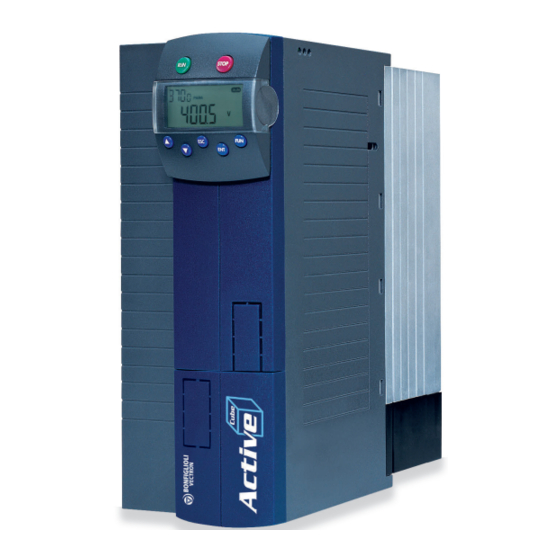
BONFIGLIOLI active cube 201 Operating Instructions Manual (285 pages)
Frequency Inverter 230 V/400 V, 0.25 kW...132 kW
Brand:
BONFIGLIOLI
| Category:
DC Drives
| Size: 19.22 MB
Table of Contents
Table of Contents
3
1 General Information about the Documentation
11
Instruction Manuals
11
This Document
12
Warranty and Liability
13
Obligation
13
Copyright
14
Storage
14
2 General Safety Instructions and Information on Use
15
Terminology
15
Designated Use
15
Misuse
16
Explosion Protection
16
Residual Risks
16
Safety and Warning Signs on Frequency Inverter
16
Warning Information and Symbols Used in the Operating Instructions
17
Hazard Classes
17
Hazard Symbols
17
Prohibition Signs
17
Personal Safety Equipment
18
Recycling
18
Grounding Symbol
18
ESD Symbol
18
Information Signs
18
Font Style in Documentation
18
Directives and Guidelines to be Adhered to by the Operator
19
Operator's General Plant Documentation
19
Operator's/Operating Staff's Responsibilities
19
Selection and Qualification of Staff
19
General Work Safety
19
Ear Protectors
19
Organizational Measures
20
General
20
Use in Combination with Third-Party Products
20
Handling and Installation
20
Electrical Connections
20
The Five Safety Rules
20
Safe Operation
21
Maintenance and Service/Troubleshooting
22
Final Decommissioning
22
Safety Instructions on Function "Safe Torque Off" (STO)
23
3 Storage and Transport
24
Storage
24
Special Safety Instructions on Transport of Heavy Frequency Inverters
24
Dimensions/Weight
25
Transfer to Place of Installation
25
Unpacking the Device
25
Bringing the Device into Installation Position
25
Sizes 1 through 6
25
Sizes 7 and 8
25
4 Scope of Supply
27
Sizes 1 and 2: ACU 201 (up to 3.0 Kw) and 401 (up to 4.0 Kw)
27
Sizes 3 and 4: ACU 201 (4.0 to 9.2 Kw) and 401 (5.5 to 15.0 Kw)
28
Size 5 ACU 401 (18.5 to 30.0 Kw)
29
Size 6 ACU 401 (37.0 to 65.0 Kw)
30
Size 7 ACU 401 (75.0 to 132.0 Kw)
31
5 Technical Data
32
General Technical Data
32
Technical Data - Control Electronic Equipment
33
ACU 201 Size 1 (0.25 to 1.1 Kw, 230 V)
35
ACU 201 Size 2 (1.5 to 3.0 Kw, 230 V)
36
ACU 201 Sizes 3 and 4 (4.0 to 9.2 Kw, 230 V)
37
ACU 401 Size 1 (0.25 to 1.5 Kw, 400 V)
38
ACU 401 Size 2 (1.85 to 4.0 Kw, 400 V)
39
ACU 401 Sizes 3 and 4 (5.5 to 15.0 Kw, 400 V)
40
ACU 401 Size 5 (18.5 to 30.0 Kw, 400 V)
41
ACU 401 Size 6 (37.0 to 65.0 Kw, 400 V)
42
ACU 401 Size 7 (75.0 to 132.0 Kw, 400 V)
43
Operation Diagrams
44
6 Mechanical Installation
46
Air Circulation
46
Sizes 1 and 2: ACU 201 (up to 3.0 Kw) and 401 (up to 4.0 KW)
46
Sizes 3 and 4: ACU 201 (4.0 to 9.2 Kw) and 401 (5.5 to 15.0 Kw)
48
Size 5: ACU 401 (18.5 to 30.0 Kw)
49
Size 6: ACU 401 (37.0 to 65.0 Kw) (Air-Cooled)
50
Size 7: ACU 401 (75.0 to 132.0 Kw)
51
7 Electrical Installation
52
EMC Information
54
Block Diagram
56
Optional Components
57
Connection of Unit
58
Dimensioning of Conductor Cross-Section
58
Typical Cross-Sections Size 1 through 7 (0.25 Kw
58
Mains Connection
60
Motor Connection
60
Length of Motor Cables, Without Filter
61
Motor Cable Length, with Output Filter Du/Dt
61
Motor Cable Length, with Sinus Filter
61
Group Drive
61
Speed Sensor Connection
61
Connection of a Braking Resistor
62
Connection by Size
63
Sizes 1 and 2: ACU 201 (up to 3.0 Kw) and 401 (up to 4.0 Kw)
63
Sizes 3 and 4: ACU 201 (4.0 to 9.2 Kw) and 401 (5.5 to 15.0 Kw)
65
Size 5 ACU 401 (18.5 to 30.0 Kw)
67
Size 6 ACU 401 (37.0 to 65.0 Kw)
69
Size 7 ACU 401 (75.0 to 132.0 Kw)
71
Control Terminals
73
External DC 24 V Power Supply
75
Relay Output
75
X13 Connection in ACU 501 and ACU 601
76
Motor Thermo-Contact
76
Control Terminals - Wiring Diagrams of Configurations
76
Configurations Overview
77
Configuration 110 - Sensorless Control
78
Configuration 111 - Sensorless Control with Technology Controller
78
Configuration 410 - Sensorless Field-Oriented Control
79
Configuration 411 -Sensorless Field-Oriented Control with Technology Controller
79
Configuration 430 - Sensorless Field-Oriented Control, Speed and Torque Controlled
80
Configuration 210 - Field-Oriented Control, Speed Controlled
81
Configuration 211 - Field-Oriented Control with Technology Controller
82
Configuration 230 - Field-Oriented Control, Speed and Torque Controlled
82
Configuration 510 - Field-Oriented Control of Synchronous Machine, Speed Controlled
83
Configuration 511 -Field-Oriented Control of Synchronous Machine with Technology Controller
84
Configuration 530 - Field-Oriented Control of a Synchronous Machine Speed and Torque Controlled
84
Configuration 610 - Sensorless Field-Oriented Control of Synchronous Machine, Speed Controlled
85
Configuration 611 - Sensorless Field-Oriented Control of Synchronous Machine with Technology Controller
85
Configuration 630 - Sensorless Field-Oriented Control of a Synchronous Machine Speed and Torque Controlled
86
Notes on Installation as Per Ul508C
86
8 Control Unit KP500
87
Menu Structure
88
Main Menu
88
Actual Value Menu (VAL)
89
Parameter Menu (PARA)
90
Copy Menu (CPY)
91
Reading the Stored Information
91
Menu Structure
91
Selecting the Source
92
Selecting the Destination
92
Copy Operation
93
Error Messages
93
Reading Data from Control Unit
94
Activation
94
Data Transfer
95
Resetting to Normal Operation
96
Control Menu (CTRL)
96
Controlling the Motor Via the Control Unit
97
9 Commissioning of Frequency Inverter
99
Turn Mains Voltage on
99
Setup Using the Control Unit
99
Configuration
100
Data Set
102
Motor Type
103
Machine Data
103
Plausibility Check
104
Parameter Identification
105
Status Messages During Commissioning (SS
106
Warnings During Commissioning (SA
106
Error Messages During Commissioning (SF
108
Application Data
108
Acceleration and Deceleration
109
Set Points at Multifunction Input
109
Quitting Commissioning
109
Selection of an Actual Value for Display
110
Check Direction of Rotation
110
Speed Sensor
111
Speed Sensor 1
111
Speed Sensor 2
112
Set-Up Via the Communication Interface
112
10 Inverter Data
115
Serial Number
115
Optional Modules
115
Inverter Software Version
115
Set Password
115
Control Level
115
User Name
115
Configuration
116
Language
120
Programming
120
11 Machine Data
121
Rated Motor Parameters
121
Further Motor Parameters
122
Stator Resistance
122
Leakage Coefficient
122
Magnetizing Current
123
Rated Slip Correction Factor
123
Voltage Constant
124
Stator Inductance
124
Peak Current
125
Reverse Sense of Rotation
125
Internal Values
125
Speed Sensor 1
126
Operation Mode Speed Sensor 1
126
Division Marks, Speed Sensor 1
128
Gear Factor Speed Sensor 1
128
Filter Time Constant, Speed Sensor 1
129
Sensor Evaluation
130
12 System Data
131
Actual Value System
131
Volume Flow and Pressure
131
13 Operating Behavior
132
Starting Behavior
132
Starting Behavior of Sensorless Control System
132
Starting Current
133
Frequency Limit
134
Brake Release Time
134
Flux Formation
134
Stopping Behavior
136
Switch-Off Threshold
138
Holding Time
138
Direct Current Brake
138
Auto Start
139
Search Run
140
Positioning
142
Reference Positioning
142
Axle Positioning
145
14 Error Behavior and Warning Behavior
148
Overload Ixt
148
Temperature
148
Controller Status
149
IDC Compensation Limit
149
Frequency Switch-Off Limit
150
Motor Temperature
150
Phase Failure
151
Settings for Sizes 1 to 7
151
Automatic Acknowledgment of Errors/Faults
151
15 Reference Values
152
Frequency Limits
152
Slip Frequency
152
Percentage Value Limits
152
Frequency Reference Channel
152
Block Diagram
154
Reference Percentage Channel
156
Block Diagram
157
Fixed Reference Values
159
Fixed Frequencies
159
JOG Frequency
159
Fixed Percentages
160
Frequency Ramps
160
Percentage Value Ramps
162
Blocking Frequencies
163
Motor Potentiometer
164
Motorpoti (MP)
165
Motorpoti (KP)
165
Controlling the Motor Via the Control Unit
166
PWM-/Repetition Frequency Input
166
16 Control Inputs and Outputs
168
Multifunction Input MFI1
168
Analog Input MFI1A
168
Characteristic
168
Scaling
170
Tolerance Band and Hysteresis
170
Filter Time Constant
171
Error and Warning Behavior
172
Multifunction Output MFO1
173
Analog Output MFO1A
173
Output Characteristic
174
Frequency Output MFO1F
174
Scaling
175
Digital Outputs
175
Digital Message
178
Setting Frequency
179
Reference Value Reached
180
Flux Forming Finished
182
Brake Release
182
Current Limitation
182
External Fan
182
Warning Mask
183
Warning Mask, Application
186
Digital Inputs
187
Start Command
192
3-Wire Control
192
Error Acknowledgment
193
Timer
193
Thermocontact
193
N-/M Control Change-Over
193
Switch Data Set
193
Fixed Value Change-Over
194
Motor Potentiometer
194
Handshake Traverse Function
195
User Warning
195
External Error
195
Function Modules
195
Timer
195
Timer - Time Constant
196
Comparator
198
Table of Functions
200
Multiplexer/Demultiplexer
200
17 F Characteristic
202
Dynamic Voltage Pre-Control
203
18 Control Functions
204
Intelligent Current Limits
204
Voltage Controller
206
Technology Controller
212
Functions of Sensorless Control
221
Slip Compensation
221
Current Limit Value Controller
222
Functions of Field-Oriented Control
223
Current Controller
223
Advanced Current Controller
224
Torque Controller
224
Torque Preset
225
Upper and Lower Frequency Limit in Torque Control
225
Limit Value Sources
226
Switching over between Speed Control and Torque Control
226
Speed Controller
226
Limitation of Speed Controller
228
Limit Value Sources
229
Integral Time Speed Compensation
230
Acceleration Pre-Control
230
Field Controller
231
Limitation of Field Controller
232
Modulation Controller
232
Limitation of Modulation Controller
233
19 Special Functions
234
Pulse Width Modulation
234
Fan
235
Bus Controller
235
Brake Chopper and Brake Resistance
236
Dimensioning of Brake Resistor
237
Motor Circuit Breaker
238
Motor Protection by I 2 T Monitoring
242
V-Belt Monitoring
244
Functions of Field-Oriented Control
245
Motor Chopper
245
Temperature Adjustment
246
Speed Sensor Monitoring
247
Traverse Function
247
Profibus/Internal Notation Converter
249
20 Actual Values
251
Actual Values of Frequency Inverter
251
STO Status
253
Actual Values of Machine
253
Actual Value Memory
254
Actual Values of the System
255
Actual Value System
255
Volumetric Flow and Pressure
256
21 Error Protocol
257
List of Errors
257
Error Messages
257
Error Environment
261
22 Operational and Error Diagnosis
263
Status Display
263
Status of Digital Signals
263
Controller Status
264
Warning Status and Warning Status Application
265
23 List of Parameters
267
Actual Value Menu (VAL)
267
Parameter Menu (PARA)
270
Index
280
Functions of Control Terminals (Table)
282
Advertisement
BONFIGLIOLI active cube 201 Quick Start Manual (124 pages)
active cube series
Brand:
BONFIGLIOLI
| Category:
DC Drives
| Size: 6.55 MB
Table of Contents
Italiano
4
Table of Contents
4
1 Istruzioni DI Sicurezza Relative Alla Funzione "Arresto in Sicurezza Della Coppia" (STO)
5
2 Installazione Meccanica
6
3 Installazione Elettrica
9
Avvertenze EMI
9
ACTIVE Cube 201 (Fino a 3,0 Kw) E 401 (Fino a 4,0 Kw)
9
ACTIVE Cube 201 (da 4,0 a 9,2 Kw) E 401 (da 5,5 a 15,0 Kw)
10
ACTIVE Cube 401 (da 18,5 a 30,0 Kw)
10
ACTIVE Cube 401 (da 37,0 a 65,0 Kw)
11
ACTIVE Cube 401 (da 75,0 Kw a 132,0 Kw)
12
Morsetti DI Comando
14
Tensione DI Alimentazione Esterna 24 V
14
4 Messa in Servizio Dell'unità DI Comando KP500
15
Funzioni Dei Tasti
15
Messa in Servizio Guidata
15
5 Impostazioni Dei Parametri
18
6 Grandezze DI Funzionamento
21
7 Messaggi Dell'unità DI Comando
22
Messaggi DI Avviso Ed Errore Durante Il Funzionamento
23
Messaggi DI Avviso Ed Errore Durante la Messa in Servizio
24
English
28
1 Safety Instructions for "Safe Torque Off" Function (STO)
29
2 Mechanical Installation
30
3 Electrical Installation
33
EMC Information
33
ACTIVE Cube 201 (up to 3.0 Kw) and 401 (up to 4.0 Kw)
33
ACTIVE Cube 201 (4.0 to 9.2 Kw) and 401 (5.5 to 15.0 Kw)
34
ACTIVE Cube 401 (18.5 to 30.0 Kw)
34
ACTIVE Cube 401 (37.0 to 65.0 Kw)
35
ACTIVE Cube 401 (75.0 Kw to 132.0 Kw)
36
Control Terminals
38
External 24 VDC Voltage Supply
38
4 Commissioning Via the Control Unit KP500
39
Functions of Keys
39
Guided Commissioning
39
5 Parameter Settings
42
6 Actual Values
45
7 Control Unit Messages
46
Warning and Error Messages During Operation
47
Warning and Error Messages During Guided Commissioning
48
Deutsch
52
1 Sicherheitshinweise zur Funktion "Sicher Abgeschaltetes Moment" (STO)
53
2 Mechanische Installation
54
3 Elektrische Installation
57
EMV-Hinweise
57
ACTIVE Cube 201 (bis 3,0 Kw) und 401 (bis 4,0 Kw)
57
ACTIVE Cube 201 (4,0 bis 9,2 Kw) und 401 (5,5 bis 15,0 Kw)
58
ACTIVE Cube 401 (18,5 bis 30,0 Kw)
58
ACTIVE Cube 401 (37,0 bis 65,0 Kw)
59
ACTIVE Cube 401 (75,0 Kw bis 132,0 Kw)
60
Steuerklemmen
62
Externe 24 V Spannungsversorgung
62
4 Inbetriebnahme mit der Bedieneinheit KP500
63
Tastenfunktionen
63
Geführte Inbetriebnahme
64
5 Parametereinstellungen
66
6 Istwerte
69
7 Meldungen der Bedieneinheit
70
Warn- und Fehlermeldungen während des Betriebs
71
Warn- und Fehlermeldungen während der Inbetriebnahme
72
Français
76
1 Instructions de Sécurité Relatives À la Fonction « Arrêt de Sécurité du Couple » (STO)
77
2 Installation Mécanique
78
3 Installation Électrique
81
Avertissements EMI
81
ACTIVE Cube 201 (Jusqu'à 3,0 Kw) Et 401 (Jusqu'à 4,0 Kw)
81
ACTIVE Cube 201 (de 4,0 À 9,2 Kw) Et 401 (de 5,5 À 15,0 Kw)
82
ACTIVE Cube 401 (de 18,5 À 30,0 Kw)
82
ACTIVE Cube 401 (de 37,0 À 65,0 Kw)
83
ACTIVE Cube 401 (de 75,0 Kw À 132,0 Kw)
84
Bornes de Commande
86
Tension D'alimentation Externe 24 V
86
4 Mise en Service de L'unité de Commande KP500
87
Fonction des Touches
87
Mise en Service Guidée
87
5 Configuration des Paramètres
90
6 Grandeurs de Fonctionnement
93
7 Messages de L'unité de Commande
94
Messages D'avertissement Et D'erreur Pendant Le Fonctionnement
95
Messages D'avertissement Et D'erreur Pendant la Mise en Service
96
Español
100
1 Instrucciones de Seguridad Relacionadas con la Función "Parada Segura del Par" (STO)
101
2 Instalación Mecánica
102
3 Instalación Eléctrica
105
Advertencias EMI
105
ACTIVE Cube 201 (hasta 3,0 Kw) y 401 (hasta 4,0 Kw)
105
ACTIVE Cube 201 (4,0 a 9,2 Kw) y 401 (5,5 a 15,0 Kw)
106
ACTIVE Cube 401 (18,5 a 30,0 Kw)
106
ACTIVE Cube 401 (37,0 a 65,0 Kw)
107
ACTIVE Cube 401 (75,0 Kw a 132,0 Kw)
108
Bornes de Control
110
Tensión de Alimentación Externa 24 V
110
4 Puesta en Servicio de la Consola de Programación KP500
111
Funciones de las Teclas
111
Puesta en Servicio Guiada
112
5 Ajuste de Los Parámetros
114
6 Valores de Funcionamiento
117
7 Mensajes de la Consola de Programación
118
Mensajes de Advertencia y Error Durante el Funcionamiento
119
Mensajes de Advertencia y Error Durante la Puesta en Servicio
120
Advertisement
Related Products
BONFIGLIOLI active cube 401
BONFIGLIOLI ACTIVE CUBE 501
BONFIGLIOLI ACTIVE CUBE 601
BONFIGLIOLI active
BONFIGLIOLI Active ACT 201-05
BONFIGLIOLI Active ACT 201-07
BONFIGLIOLI Active ACT 201-09
BONFIGLIOLI Active ACT 201-11
BONFIGLIOLI Active ACT 201-13
BONFIGLIOLI Active ACT 201-15
BONFIGLIOLI Categories
DC Drives
Engine
Inverter
Industrial Equipment
Controller
More BONFIGLIOLI Manuals
Login
Sign In
OR
Sign in with Facebook
Sign in with Google
Upload manual
Upload from disk
Upload from URL