Sign In
Upload
Download
Table of Contents
Contents
Add to my manuals
Delete from my manuals
Share
URL of this page:
HTML Link:
Bookmark this page
Add
Manual will be automatically added to "My Manuals"
Print this page
×
Bookmark added
×
Added to my manuals
Manuals
Brands
BONFIGLIOLI Manuals
DC Drives
300 Series
Installation, operation and maintenance manual
BONFIGLIOLI 300 Series Installation, Operation And Maintenance Manual
Hide thumbs
Also See for 300 Series
:
Installation use and service manual
(44 pages)
1
2
Table Of Contents
3
4
5
6
7
8
9
10
11
12
13
14
15
16
17
18
19
20
21
22
23
24
25
26
27
28
29
30
31
32
33
34
35
36
37
38
39
40
41
42
43
44
45
46
47
48
49
50
51
52
53
54
55
56
page
of
56
Go
/
56
Contents
Table of Contents
Troubleshooting
Bookmarks
Table of Contents
Table of Contents
1 General Information
Purpose of the Manual
Product Identification
Glossary and Terminology
Requesting Technical Assistance
Manufacturer's Liability
Consignment Conditions
2 Technical Information
Description of the Gear Unit
Conformity
Operating Limits and Conditions
Allowed Temperature Limits
3 Safety Information
Safety Standards
4 Handling and Transport
Packaging
Handling Instructions
Moving the Packages
Moving the Equipment
Storage
5 Installation
Installing the Gear Unit
Flanged Execution
Foot Mounting
Shaft Mounting
Installing Accessories on Solid Input and Output Shafts
Installing the Electric Motor
Installing the Hydraulic Motor
Connecting the Hydraulic Brake
Lubrication
6 Testing the Gear Unit
7 Using the Equipment
8 Maintenance
Routine Maintenance
Oil Changes
Checking Operational Efficiency
Cleaning
9 Replacing Parts
Removing the Motor
Decommissioning the Gear Unit
10 Troubleshooting
Annex 1 - Checking the Oil Level on Atex-Specified Gear Units
Annex 2 - Lubricant Charge Quantity
Annex 3 - Mounting Positions and Plug Positions
Advertisement
Quick Links
1
Product Identification
2
Description of the Gear Unit
3
Lubrication
4
Oil Changes
5
Replacing Parts
Download this manual
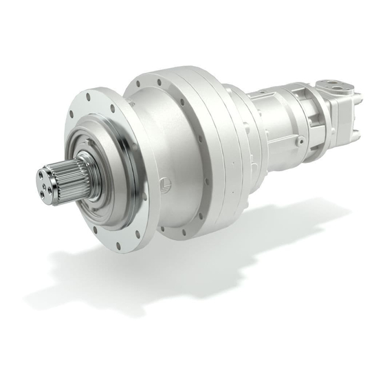
300 - 300M Series
Installation, Operation
and Maintenance Manual
PRODUCTS &
SOLUTIONS
INCLUDED
Table of
Contents
Previous
Page
Next
Page
1
2
3
4
5
Advertisement
Table of Contents
Need help?
Do you have a question about the 300 Series and is the answer not in the manual?
Ask a question
Questions and answers
Related Manuals for BONFIGLIOLI 300 Series
DC Drives BONFIGLIOLI 300 Series Installation Use And Service Manual
(44 pages)
DC Drives BONFIGLIOLI 307 Installation, Operation And Maintenance Manual
(56 pages)
DC Drives BONFIGLIOLI ACTIVE CUBE 201 Operating Instructions Manual
Frequency inverter 230 v/400 v, 0.25 kw...132 kw (285 pages)
DC Drives BONFIGLIOLI Agile Operating Instructions Manual
Frequency inverter 230 v / 400 0.09 kw ... 11 kw (360 pages)
DC Drives Bonfiglioli Act 201 Operating Instructions Manual
Vectron active 201/401 series 230v/400v 0.55 kw ... 132. kw frequency inverter (218 pages)
DC Drives BONFIGLIOLI Active Cube Series Complement To Operating Instructions
Liquid cooling (32 pages)
DC Drives BONFIGLIOLI ACTIVE Manual
Canopen communication module cm-can, 230v/400v (50 pages)
DC Drives BONFIGLIOLI Agile AGL 401-05 Quick Start Manual
(35 pages)
DC Drives BONFIGLIOLI agl 402 Quick Start Manual
Agile series (29 pages)
DC Drives BONFIGLIOLI Agile Series Application Manual Functional Safety
Vectron (42 pages)
DC Drives BONFIGLIOLI Vectron Active Cube User Manual
Canopen communication module cm-can frequency inverter 230 v / 400 v (240 pages)
DC Drives BONFIGLIOLI Vectron Manual
Active cube expansion module em-res-03 230 v/400 v (74 pages)
DC Drives BONFIGLIOLI ACTIVE Applications Manual
(30 pages)
DC Drives BONFIGLIOLI ACTIVE Manual
Profibus-dp, communication module cm-pdp, frequency inverter 230v/400v (44 pages)
DC Drives BONFIGLIOLI AGILE Applications Manual
(166 pages)
This manual is also suitable for:
300m series
300
301
303
304
305
...
Show all
306
307
309
310
311
313
314
315
316
317
318
319
321
323
325
Table of Contents
Save PDF
Print
Rename the bookmark
Delete bookmark?
Delete from my manuals?
Login
Sign In
OR
Sign in with Facebook
Sign in with Google
Upload manual
Upload from disk
Upload from URL


Need help?
Do you have a question about the 300 Series and is the answer not in the manual?
Questions and answers