Table of Contents
Advertisement
Quick Links
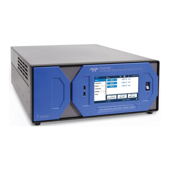
Nitrogen Oxides Analyzer
Copyright 2011-2016
Teledyne API
User Manual
Model T200H/M
© TELEDYNE API
9970 Carroll Canyon Road
SAN DIEGO, CA 92131-1106
USA
Toll-free Phone:
Phone:
Fax:
Email:
Website:
800-324-5190
+1 858-657-9800
+1 858-657-9816
api-sales@teledyne.com
http://www.teledyne-api.com/
07270D DCN7141
28 April 2016
Advertisement
Table of Contents

Subscribe to Our Youtube Channel
Related Manuals for Teledyne T200H


Summary of Contents for Teledyne T200H
- Page 1 User Manual Model T200H/M Nitrogen Oxides Analyzer © TELEDYNE API 9970 Carroll Canyon Road SAN DIEGO, CA 92131-1106 Toll-free Phone: 800-324-5190 Phone: +1 858-657-9800 Fax: +1 858-657-9816 Email: api-sales@teledyne.com Website: http://www.teledyne-api.com/ Copyright 2011-2016 07270D DCN7141 Teledyne API 28 April 2016...
- Page 3 NOTICE OF COPYRIGHT © 2011-2016 Teledyne API. All rights reserved. TRADEMARKS All trademarks, registered trademarks, brand names or product names appearing in this document are the property of their respective owners and are used herein for identification purposes only. 07270D DCN7141...
- Page 4 Teledyne API - Model T200H/T200M Operation Manual This page intentionally left blank. 07270D DCN7141...
-
Page 5: Safety Messages
For Technical Assistance regarding the use and maintenance of this instrument or any other Teledyne API product, contact Teledyne API’s Technical Support Department: Telephone: 800-324-5190 Email: sda_techsupport@teledyne.com or access any of the service options on our website at http://www.teledyne-api.com/ 07270D DCN7141... -
Page 6: Consignes De Sécurité
Teledyne API - Model T200H/T200M Operation Manual CONSIGNES DE SÉCURITÉ Des consignes de sécurité importantes sont fournies tout au long du présent manuel dans le but d’éviter des blessures corporelles ou d’endommager les instruments. Veuillez lire attentivement ces consignes. Chaque consigne de sécurité est représentée par un pictogramme d’alerte de sécurité;... -
Page 7: Warranty
For anti-ESD handling and packing instructions please refer to the manual, Fundamentals of ESD, PN 04786, in its “Packing Components for Return to Teledyne API’s Customer Service” section. The manual can be downloaded from our website at http://www.teledyne-api.com... - Page 8 Teledyne API - Model T200H/T200M Operation Manual This page intentionally left blank. 07270D DCN7141...
-
Page 9: About This Manual
05147 Menu Trees and Software Documentation (inserted as Appendix A in this manual) 07351 Spare Parts List - T200H (located in Appendix B of this manual) 07367 Spare Parts List - T200M (located in Appendix B of this manual) 05149... - Page 10 Teledyne API - Model T200H/T200M Operation Manual This page intentionally left blank. viii 07270D DCN7141...
-
Page 11: Revision History
REVISION HISTORY This section provides information regarding changes to this manual. T200H/T200M Operation Manual PN 07270 Date Change Summary 2016 April 28 7141 Streamline content; make administrative fixes 2013 February 01 6646 Clarify Converter Efficiency value and various updates 2012 June 20... - Page 12 Teledyne API - Model T200H/T200M Operation Manual This page intentionally left blank. 07270D DCN7141...
-
Page 13: Table Of Contents
3.4.8. Connecting the Communications Ports ........................40 3.5. Pneumatic Connections..............................42 3.5.1. About Zero Air and Calibration (Span) Gases ......................42 3.5.2. Pneumatic Connections to T200H/M Basic Configuration ..................44 3.5.3. Connections with Internal Valve Options Installed ....................48 3.6. Initial Operation ................................57 3.6.1. -
Page 14: Table Of Contents
4.15.1. Remote Operation Using the External Digital I/O ....................164 4.15.2. Remote Operation .............................. 166 4.15.3. Additional Communications Documentation ....................... 173 4.15.4. Using the T200H/M with a Hessen Protocol Network ..................173 5. Calibration Procedures ................................. 181 5.1.1. Interferents for NO Measurements ........................ - Page 15 Teledyne API - Model T200H/T200M Operation Manual Table of Contents 7.2.2. T200M Internal Gas Flow Diagrams ........................227 7.2.3. Zero or Low Flow Problems ..........................229 7.2.4. High Flow ................................231 7.2.5. Sample Flow is Zero or Low But Analyzer Reports Correct Flow ................. 231 7.3.
-
Page 16: List Of Figures
Figure 3-20: T200M – Internal Pneumatics with Ambient Zero-Span Valve Option 50A .........50 Figure 3-21: T200H - Internal Pneumatics for Zero Scrubber/Dual Pressurized Span, Option 50D ....53 Figure 3-22: T200M - Internal Pneumatics for Zero Scrubber/Dual Pressurized Span, Option 50D ....54 Figure 3-23: T200H –... - Page 17 Relay Board PCA ........................221 Figure 7-5: T200H – Basic Internal Gas Flow ....................224 Figure 7-6: T200H – Internal Gas Flow with Ambient Zero Span, OPT 50A ..........225 Figure 7-7: T200H – Internal Gas Flow with O Sensor, OPT 65A ..............226 Figure 7-8: T200M –...
-
Page 18: List Of Tables
Analog Output Pin Assignments ....................129 Table 4-19: Analog Output Current Loop Range ..................130 Table 4-20: Example of Analog Output Configuration for T200H/M .............130 Table 4-21: DIAG - Analog I/O Functions .....................132 Table 4-22: Analog Output Data Type Default Settings ................138... -
Page 19: List Of Appendices
Table 8-1: List of Interferents ........................271 Table 8-2: T200H/M Valve Cycle Phases ....................274 Table 8-3: T200H/M Critical Flow Orifice Diameters and Gas Flow Rates ..........278 Table 8-4: Thermocouple Configuration Jumper (JP5) Pin-Outs ..............296 Table 8-5: Typical Thermocouple Settings ....................297 LIST OF APPENDICES... - Page 20 Table of Contents Teledyne API - Model T200H/T200M Operation Manual This page intentionally left blank. xviii 07270D DCN7141...
-
Page 21: Introduction, Features, And Options
1. INTRODUCTION, FEATURES, AND OPTIONS 1.1. OVERVIEW The Models T200H and T200M (also referred to in this manual as T200H/M when applicable to both models) use the proven chemiluminescence measurement principle, coupled with state-of-the-art microprocessor technology for monitoring high and medium levels of nitrogen oxides. -
Page 22: Options
Cannot be used with rack mount slides. CAUTION – GENERAL SAFETY HAZARD THE T200H OR T200M ANALYZER WEIGHS ABOUT 18 KG (40 POUNDS). TO AVOID PERSONAL INJURY WE RECOMMEND THAT TWO PERSONS LIFT AND CARRY THE ANALYZER. DISCONNECT ALL CABLES AND TUBING FROM THE ANALYZER BEFORE MOVING IT. - Page 23 Teledyne API - Model T200H/T200M Operation Manual Introduction, Features, and Options Option Option Description/Notes Reference Number Communication Cables For remote serial, network and Internet communication with the analyzer. Type Description Shielded, straight-through DB-9F to DB-25M cable, about RS-232 1.8 m long. Used to interface with older computers or Section 3.4.8...
- Page 24 Introduction, Features, and Options Teledyne API - Model T200H/T200M Operation Manual This page intentionally left blank. 07270D DCN7141...
-
Page 25: Specifications And Approvals
250 cm /min ± 10% through bypass Gas Flow Rates manifold • 290 cm³/min total flow ± 10% Sensor option adds 80 cm³/min to total flow through T200H/M when installed. Rating Typical Power Consumption 110V-120V, 60 Hz 3.0A 175W T200H: AC Power 220V-240V, 50/60 Hz 3.0A... -
Page 26: Approvals And Certifications
Multidrop RS232 3 4-20mA current outputs 2.2. APPROVALS AND CERTIFICATIONS The Teledyne API Nitrogen Oxides Analyzers T200H and T200M were tested and certified for Safety and Electromagnetic Compatibility (EMC). This section presents the compliance statements for those requirements and directives. -
Page 27: Getting Started
3.1. UNPACKING AND INITIAL SETUP CAUTION The T200H and the T200M each weighs about 18 kg (40 pounds) without options installed. To avoid personal injury, we recommend using two persons to lift and carry the analyzer. CAUTION – Avoid Warranty Invalidation Printed Circuit Assemblies (PCAs) are sensitive to electro-static discharges too small to be felt by the human nervous system. -
Page 28: Ventilation Clearance
Getting Started Teledyne API - Model T200H/T200M Operation Manual 4. Inspect the interior of the instrument to ensure all circuit boards and other components are intact and properly seated. 5. Check the connectors of the various internal wiring harnesses and pneumatic hoses to make sure they are firmly and properly seated. -
Page 29: Figure 3-2: Display Screen And Touch Control
Teledyne API - Model T200H/T200M Operation Manual Getting Started Figure 3-2: Display Screen and Touch Control CAUTION – Avoid Damaging Touch screen Do not use hard-surfaced instruments such as pens to operate the touch screen. The front panel liquid crystal display screen includes touch control. Upon analyzer start- up, the screen shows a splash screen and other initialization indicators before the main display appears, similar to Figure 3-2 above (may or may not display a Fault alarm). -
Page 30: Table 3-1: Display Screen And Touch Control Description
Getting Started Teledyne API - Model T200H/T200M Operation Manual Table 3-1: Display Screen and Touch Control Description Field Description/Function Status LEDs indicating the states of Sample, Calibration and Fault, as follows: Name Color State Definition Unit is not operating in sample mode, DAS is disabled. -
Page 31: Figure 3-3: Display/Touch Control Screen Mapped To Menu Charts
Teledyne API - Model T200H/T200M Operation Manual Getting Started Figure 3-3: Display/Touch Control Screen Mapped to Menu Charts The rear panel is illustrated in Figure 3-4 and described in Table 3-2. 07270D DCN7141... -
Page 32: Figure 3-4: T200H/M Rear Panel Layout
Getting Started Teledyne API - Model T200H/T200M Operation Manual Figure 3-4: T200H/M Rear Panel Layout Table 3-2: Rear Panel Description Component Function Cooling Fan Pulls ambient air into chassis through side vents and exhausts through rear. Connector for three-prong cord to apply AC power to the analyzer. -
Page 33: Figure 3-5: T200H/M Internal Layout
Teledyne API - Model T200H/T200M Operation Manual Getting Started Figure 3-5: T200H/M Internal Layout 07270D DCN7141... -
Page 34: Electrical Connections
CAUTION ENSURE THAT the voltage and frequency specifications on the rear panel Label of the instrument ARE compatibLE with the local power before plugging the T200H/M into line power. Do not plug in the power cord if the voltage or frequency is incorrect. -
Page 35: Analog Inputs (Option 64) Connections
The T200H/M is equipped with four analog output channels accessible through a connector on the back panel of the instrument. Each of these outputs may be set to reflect the value of any of the instrument’s DAS data types. (see Table A-6 of T200H/M Appendix A). -
Page 36: Figure 3-7: Analog Output Connector
100 ppm UPDATE 5 sec See Table A-6 of T200H/M Appendix A for definitions of these DAS data types Optional current loop outputs are available for analog output channels A1-A3. On analyzers with O sensor options installed, DAS parameter O2CONC is assigned to output A4. -
Page 37: Connecting The Status Outputs
Teledyne API - Model T200H/T200M Operation Manual Getting Started 3.4.4. CONNECTING THE STATUS OUTPUTS The analyzer’s status outputs to interface with a device that accepts logic-level digital inputs, such as programmable logic controller (PLC) chips, are accessed through a 12 pin connector labeled STATUS on the analyzer’s rear panel. -
Page 38: Current Loop Analog Outputs (Opt 41) Setup
This option adds isolated, voltage-to-current conversion circuitry to the analyzer’s analog outputs. This option may be ordered separately for the first three of the analog outputs and can be installed at the factory or added later. Call Teledyne API sales for pricing and availability. - Page 39 Teledyne API - Model T200H/T200M Operation Manual Getting Started 3.4.5.1. Converting Current Loop Analog Outputs to Standard Voltage Outputs. CAUTION – Avoid Warranty Invalidation Printed Circuit Assemblies (PCAs) are sensitive to electro-static discharges too small to be felt by the human nervous system. Failure to use Electro-Static Discharge (ESD) protection when working with electronic assemblies will void the instrument warranty.
-
Page 40: Connecting The Control Inputs
Getting Started Teledyne API - Model T200H/T200M Operation Manual 3.4.6. CONNECTING THE CONTROL INPUTS Control Inputs are used to remotely activate the zero and span calibration modes. Locate the 10-pin connector labeled CONTROL IN on the analyzer’s rear panel. There are two methods for energizing the control inputs. The internal +5V available from the pin labeled “+”... -
Page 41: Connecting The Alarm Relay Option (Opt 61)
Getting Started 3.4.7. CONNECTING THE ALARM RELAY OPTION (OPT 61) The T200H/M can be equipped with a set of 2 concentration alarms. Each alarm can be independently enabled or disabled as well as programmed with its own, individual alarm limit point (see Section 4.14 for details on programming the alarms). -
Page 42: Connecting The Communications Ports
Ethernet interface connector to an Ethernet port. See Section 4.11.7 for configuration instructions. The T200H/M firmware supports dynamic IP addressing or DHCP. If your network Note also supports DHCP, the analyzer will automatically configure its LAN connection appropriately. -
Page 43: Figure 3-12: T200H/M Multidrop Card
CPU card (see Figure 3-12). One Option 62 is required for each analyzer along with one 6’ straight-through, DB9 male DB9 Female cable (P/N WR0000101). If your unit has a Teledyne API RS-232 multidrop card (Option 62), see Section 4.11.9 for instructions on setting it up. -
Page 44: Pneumatic Connections
Getting Started Teledyne API - Model T200H/T200M Operation Manual 3.5. PNEUMATIC CONNECTIONS To prevent dust from getting into the analyzer, it was shipped with small plugs Note inserted into each of the pneumatic fittings on the rear panel. Remove and store the dust plugs for future use, such as storage, moving, shipping. -
Page 45: Table 3-11: Nist-Srm's Available For Traceability Of No
Oxides of Nitrogen (NO ) in N 100 ppm If a dynamic dilution system such as the Teledyne API Model T700 is used to Note dilute high concentration gas standards to low, ambient concentrations, make sure that the NO concentration of the reference gas matches the dilution range of the calibrator. -
Page 46: Pneumatic Connections To T200H/M Basic Configuration
Figure 3-13 and Figure 3-14 show the most common configurations for gas supply and exhaust lines to the Model T200H/M analyzer. Please refer to Figure 3-4 for the locations of pneumatic connections on the rear panel and Table 3-2 for the descriptions. -
Page 47: Figure 3-14: Pneumatic Connections-Basic Configuration-Using Bottled Span Gas
Teledyne API - Model T200H/T200M Operation Manual Getting Started MODEL 701 Source of SAMPLE GAS Zero Gas Removed during Generator calibration VENT here if input 3-way Valve is pressurized (High Concentration) SAMPLE EXHAUST Manual Instrument Control Valve Chassis PUMP Figure 3-14: Pneumatic Connections–Basic Configuration–Using Bottled Span Gas... -
Page 48: Figure 3-15: T200H Internal Pneumatic Block Diagram - Standard Configuration
SAMPL E PRESS URE SENSO R AUTOZERO VALVE Orifice Dia. 0.007" GENERATOR Orifice Dia. Orifice Dia. 0.003" 0.007" REACTION CELL Destruct Orifice Dia. 0.004" PUMP OZONE DRYER INSTRUMENT CHASSIS Figure 3-15: T200H Internal Pneumatic Block Diagram - Standard Configuration 07270D DCN7141... -
Page 49: Figure 3-16: T200M Internal Pneumatic Block Diagram - Standard Configuration
T200M Internal Pneumatic Block Diagram - Standard Configuration Note Pneumatic Diagrams do not reflect the physical layout of the instrument. The most significant differences between the T200H and T200M versions in regards to pneumatic flow are: • A bypass line leading directly from the particulate filter to the exhaust manifold is present on the T200H, but not in the T200M. -
Page 50: Connections With Internal Valve Options Installed
Getting Started Teledyne API - Model T200H/T200M Operation Manual 3.5.3. CONNECTIONS WITH INTERNAL VALVE OPTIONS INSTALLED If your analyzer is equipped with either the zero/span valve option (50A) or the 2-span point valve option (50D), the pneumatic connections should be made as shown in Figure... -
Page 51: Figure 3-19: T200H - Internal Pneumatics With Ambient Zero-Span Valve Option 50A
Figure 3-19 and Figure 3-20 show the internal, pneumatic layouts with the zero/span valve option installed for a Model T200H and T200M respectively. Zero/Span Valve Option SAMPLE... -
Page 52: Figure 3-20: T200M - Internal Pneumatics With Ambient Zero-Span Valve Option 50A
Getting Started Teledyne API - Model T200H/T200M Operation Manual NO/NO SAMPLE VALVE INLET Converter FLOW PRESSURE SAMPLE/ CAL SENSOR PCA VALVE SPA N GA S INLET VACUUM PRESS URE SENSO R Zero/Span Valve Option SAMPL E PRESS URE ZERO GAS... - Page 53 , followed by 50% volume of charcoal to absorb NO . Chemical Kit 00433 is available from Teledyne API for changing these chemicals (see Maintenance Schedule, Table 6-1), which must be disposed of according to local regulations. The dual pressurized span valves of Option 50D are a special set of valves that allows two separate NO mixtures to enter the analyzer from two independent sources.
-
Page 54: Table 3-13: Two-Point Span Valve Operating States
Getting Started Teledyne API - Model T200H/T200M Operation Manual The state of the optional valves can be controlled: • manually from the analyzer’s front panel by using the SIGNAL I/O submenu located under the DIAG menu (Section 4.13.2) • by activating the instrument’s CAL or AutoCal features (Section 5.8) •... -
Page 55: Figure 3-21: T200H - Internal Pneumatics For Zero Scrubber/Dual Pressurized Span, Option 50D
Orifice Dia. Orifice Dia. 0.007" 0.003" EX HA UST HIGH SPAN OUTLET LOW SPAN REACTION CELL Destruct Orifice Dia. 0.004" PUMP OZONE DRYER Filter INSTRUMENT CHASSIS Figure 3-21: T200H - Internal Pneumatics for Zero Scrubber/Dual Pressurized Span, Option 50D 07270D DCN7141... -
Page 56: Figure 3-22: T200M - Internal Pneumatics For Zero Scrubber/Dual Pressurized Span, Option 50D
Getting Started Teledyne API - Model T200H/T200M Operation Manual SAMPLE SAMPLE/ CAL VALVE INLET ZERO/SPAN NO/NO FLOW PRESSURE VALVE VALVE SENSOR PCA ZERO GAS INLET Converter VACUUM PRESS URE BYPASS SPAN SENSO R GAS VENT SAMPL E HI/LOW SPAN PRESS URE... -
Page 57: Figure 3-23: T200H - Internal Pneumatics With O2 Sensor Option 65A
EX HA UST OUTLET AUTOZERO VALVE GENERATOR Sensor Orifice Dia. Orifice Dia. Orifice Dia. 0.004" 0.007" 0.007" REACTION CELL Orifice Dia. Destruct 0.004" PUMP OZONE DRYER INSTRUMENT CHASSIS Figure 3-23: T200H – Internal Pneumatics with O2 Sensor Option 65A 07270D DCN7141... -
Page 58: Figure 3-24: T200M - Internal Pneumatics With O
Getting Started Teledyne API - Model T200H/T200M Operation Manual NO/NO FLOW PRESSURE VALVE SENSOR PCA SAMPLE Converter INLET VACUUM PRESS URE SENSO R SAMPL E PRESS URE SENSOR SENSO R OPTION EX HA UST OUTLET AUTOZERO VALVE GENERATOR Sensor Orifice Dia. -
Page 59: Initial Operation
3.6. INITIAL OPERATION CAUTION! If the presence of ozone is detected at any time, call Teledyne API Technical Support as soon as possible: 800-324-5190 or email: sda_techsupport@teledyne.com If you are unfamiliar with the theory of operation of the T200H/M analyzer, we recommend that you read Section 8 before proceeding. -
Page 60: Functional Check
Getting Started Teledyne API - Model T200H/T200M Operation Manual 3.6.3. FUNCTIONAL CHECK After the analyzer’s components have warmed up for at least 30 minutes, verify that the software properly supports any hardware options that were installed. Check to make sure that the analyzer is functioning within allowable operating parameters. -
Page 61: Calibration
Once you have completed the following set-up procedures, please fill out the Note quality questionnaire that was shipped with your unit and return it to Teledyne API. This information is vital to our efforts in continuously improving our service and our products. - Page 62 Getting Started Teledyne API - Model T200H/T200M Operation Manual STEP 1 - Set Units: To select the concentration units of measure press: SAMPLE A1:NXCNC1=100PPM NOX=XXX.X < TST TST > SETUP SETUP X.X PRIMARY SETUP MENU CFG DAS RNGE PASS CLK MORE EXIT SETUP X.X...
- Page 63 Teledyne API - Model T200H/T200M Operation Manual Getting Started STEP 2 - Dilution Ratio: If the dilution ratio option is enabled on your T200H/M and your application involves diluting the sample gas before it enters the analyzer, set the dilution ratio as follows: SAMPLE A1:NXCNC1=100PPM NOX=XXX.X...
- Page 64 Getting Started Teledyne API - Model T200H/T200M Operation Manual STEP 3 – Set NO and NO span gas concentrations: Set the expected NO and NO span gas concentration. These should be 80% of range of concentration values likely to be encountered in this application. The default factory setting is 100 ppm.
- Page 65 Teledyne API - Model T200H/T200M Operation Manual Getting Started STEP 4 – Zero/Span Calibration : To perform the zero/span calibration procedure: SAMPLE A1:NXCNC1=100PPM NOX=XXX.X Set the Display to show the NOX STB test Analyzer continues to < TST TST >...
-
Page 66: Basic O 2 Sensor Calibration Procedure
Control Valve Chassis PUMP Figure 3-25: Sensor Calibration Set Up SENSOR ZERO GAS: Teledyne API’ recommends using pure N when calibration the zero point of your O sensor option. SENSOR SPAN GAS: Teledyne API’ recommends using 21% O in N... - Page 67 Teledyne API - Model T200H/T200M Operation Manual Getting Started 3.7.2.2. O Calibration Method STEP 1 – Set O span gas concentration : Set the expected O span gas concentration. This should be equal to the percent concentration of the O span gas of the selected reporting range (default factory setting = 20.8%;...
- Page 68 Getting Started Teledyne API - Model T200H/T200M Operation Manual STEP 2 – Activate O sensor stability function To change the stability test function from NO concentration to the O sensor output, press: SAMPLE A1:NXCNC1=100PPM NOX=XXX.X SETUP X.X 0) DAS_HOLD_OFF=15.0 Minutes <...
- Page 69 <TST TST> ENTR CONC EXIT M-P CAL O2 STB=X.XX % NOX=XXX.X EXIT at this point returns to the <TST TST> ENTR CONC EXIT SAMPLE menu. The Model T200H/M analyzer is now ready for operation. 07270D DCN7141...
- Page 70 Getting Started Teledyne API - Model T200H/T200M Operation Manual This page intentionally left blank. 07270D DCN7141...
-
Page 71: Operating Instructions
25:00:00. Once you adjust the setting to an allowable value, the ENTR button will re-appear. 4.1. OVERVIEW OF OPERATING MODES The T200H/M software has a variety of operating modes. Most commonly, the analyzer will be operating in SAMPLE mode. In this mode, a continuous read-out of the NO, and NO concentrations are displayed on the front panel and are available to be output as analog signals from the analyzer’s rear panel terminals. - Page 72 Operating Instructions Teledyne API - Model T200H/T200M Operation Manual Figure 4-1: Front Panel Display with “SAMPLE” Indicated in the Mode Field The mode field of the front panel display indicates to the user which operating mode the unit is currently running.
-
Page 73: Sample Mode
Teledyne API - Model T200H/T200M Operation Manual Operating Instructions Table 4-1: Analyzer Operating Modes MODE EXPLANATION SAMPLE Sampling normally, flashing text indicates adaptive filter is on. M-P CAL This is the basic calibration mode of the instrument and is activated by pressing the CAL key. -
Page 74: Table 4-2: Test Functions Defined
Operating Instructions Teledyne API - Model T200H/T200M Operation Manual Table 4-2: Test Functions Defined DISPLAY PARAMETER UNITS DESCRIPTION A1:NXCNC1=100 PPM Analog output A2:N0CNC1=100 PPM These functions show the default settings for the enabled analog range output channels. See section 4.13.4 for more information. -
Page 75: Warning Messages
Teledyne API - Model T200H/T200M Operation Manual Operating Instructions SAMPLE A1:NXCNC1=100 PPM NOX = XXX < TST TST > CAL SETUP A1:NXCNC1=100 PPM A2:NOCNC1=100 PPM A3:N2CNC1=25 PPM Toggle <TST TST> to scroll A4:NXCNC2=100% RANGE through list of functions NOX STB... -
Page 76: Table 4-3: List Of Warning Messages
“XXX.X” indicates the actual auto-zero reading at the time of the warning. BOX TEMP WARNING The temperature inside the T200H/M chassis is outside the specified limits. CANNOT DYN SPAN Remote span calibration failed while the dynamic span feature was ON. -
Page 77: Calibration Mode
4.3. CALIBRATION MODE 4.3.1. CALIBRATION FUNCTIONS Pressing the CAL key switches the T200H/M into calibration mode. In this mode, the user can calibrate the instrument with the use of calibrated zero or span gases. If the instrument includes the zero/span valve option, the display will also include CALZ and CALS buttons. -
Page 78: Setup Cfg: Viewing The Analyzer'sconfiguration Information
Operating Instructions Teledyne API - Model T200H/T200M Operation Manual Table 4-5: Secondary Setup Mode Features and Functions KEYPAD MANUAL MODE OR FEATURE DESCRIPTION LABEL SECTION Used to set up and operate the analyzer’s various external I/O External Communication 6.11 &... -
Page 79: Setup Acal: Automatic Calibration (Autocal)
A menu tree showing the ACAL menu’s entire structure can be found in Appendix A-1 of this manual. Instructions for using the AUTOCAL feature are located in the Section 5.8 of this manual along with all other information related to calibrating the T200H/M analyzer. 07270D DCN7141... -
Page 80: Setup Das - Using The Data Acquisition System (Das)
4.7. SETUP DAS - USING THE DATA ACQUISITION SYSTEM (DAS) The T200H/M analyzer contains a flexible and powerful, internal data acquisition system (DAS) that enables the analyzer to store concentration and calibration data as well as a host of diagnostic parameters. The data points can cover days, weeks or months of valuable measurements, depending on how the DAS is configured. -
Page 81: Das Structure
Users may create up to 20 data channels. For each channel one triggering event is selected and one or all of the T200H/M’s 25 data parameters are allowed. The number of parameters and channels is limited by available memory. -
Page 82: Table 4-8: Das Data Parameter Functions
For each Teledyne API analyzer model, the list of available data parameters is different, fully defined and not customizable (see Appendix A for a list of T200H/M parameters). -
Page 83: Default Das Channels
4.7.2. DEFAULT DAS CHANNELS The T200H/M is configured with a basic DAS configuration, which is enabled by default. New data channels are also enabled by default but each channel may be turned off for later or occasional use. -
Page 84: Table 4-9: T200H/M Default Das Configuration
Operating Instructions Teledyne API - Model T200H/T200M Operation Manual Table 4-9: T200H/M Default DAS Configuration PARAMETERS CHANNELS with PROPERTIES NAME MODE EVENT PRECISION SAMPLES Name: CONC NOXCNC1 Event: ATIMER Sample Period: 000:00:01 NOCNC1 Report Period: 000:01:00 Number of Records: 800... - Page 85 Teledyne API - Model T200H/T200M Operation Manual Operating Instructions 4.7.2.1. Viewing DAS Data and Settings DAS data and settings can be viewed on the front panel through the following keystroke sequence. FRONT PANEL CONTROL BUTTON FUNCTIONS BUTTON FUNCTION SAMPLE A1:NXCNC1=100PPM NOX=XXX.X...
- Page 86 Operating Instructions Teledyne API - Model T200H/T200M Operation Manual 4.7.2.2. Editing DAS Data Channels DAS configuration is most conveniently done through the APICOM remote control program. The following sequence of touchscreen button presses shows how to edit using the front panel.
- Page 87 EXIT EXIT ignores the new string and returns to the previous menu. Press each key repeatedly to cycle through the list of available trigger events. See Appendix A for list of DAS trigger events available on the T200H/M. 07270D DCN7141...
- Page 88 Operating Instructions Teledyne API - Model T200H/T200M Operation Manual 4.7.2.4. Editing DAS Parameters Data channels can be edited individually from the front panel without affecting other data channels. However, when editing a data channel, such as during adding, deleting or editing parameters, all data for that particular channel will be lost, because the DAS can store only data of one format (number of parameter columns etc.) for any given channel.
- Page 89 SETUP X.X STORE NUM. SAMPLES: OFF <SET EDIT EXIT SETUP X.X STORE NUM. SAMPLES: OFF ENTR EXIT <SET Returns to previous Functions Turn ON or OFF See Appendix A-5 for list of DAS parameters available on the T200H/M. 07270D DCN7141...
- Page 90 Operating Instructions Teledyne API - Model T200H/T200M Operation Manual 4.7.2.5. Sample Period and Report Period The DAS defines two principal time periods by which sample readings are taken and permanently recorded: • SAMPLE PERIOD: Determines how often DAS temporarily records a sample reading of the parameter in volatile memory.
- Page 91 Teledyne API - Model T200H/T200M Operation Manual Operating Instructions To define the REPORT PERIOD, follow the instruction shown in Section 4.7.2.2 then press: From the DATA ACQUISITION menu (see Section 6.7.2.2) SETUP X.X ENTER DAS PASS: 818 Changing the SAMPLE...
- Page 92 Operating Instructions Teledyne API - Model T200H/T200M Operation Manual 4.7.2.7. Number of Records The DAS is capable of capturing several months worth of data, depending on the configuration. Every additional data channel, parameter, number of samples setting etc. will reduce the maximum amount of data points somewhat. In general, however, the maximum data capacity is divided amongst all channels (max: 20) and parameters (max: 50 per channel).
- Page 93 Operating Instructions 4.7.2.8. RS-232 Report Function The T200H/M DAS can automatically report data to the communications ports, where they can be captured with a terminal emulation program or simply viewed by the user. To enable automatic COM port reporting, follow the instruction shown in Section 4.7.2.2 then press:...
- Page 94 4.7.2.11. Disabling/Enabling Data Channels Data channels can be temporarily disabled, which can reduce the read/write wear on the disk-on-module. The HIRES channel of the T200H/M, for example, is disabled by default. To disable a data channel, follow the instruction shown in Section 4.7.2.2 then press:...
- Page 95 Teledyne API - Model T200H/T200M Operation Manual Operating Instructions 4.7.2.12. HOLDOFF Feature The DAS HOLDOFF feature allows to prevent data collection during calibrations and during the DAS_HOLDOFF period enabled and specified in the VARS (Section 4.12). To enable or disable the HOLDOFF for any one DAS channel, follow the instruction shown in Section 4.7.2.2 then press:...
-
Page 96: Remote Das Configuration
Operating Instructions Teledyne API - Model T200H/T200M Operation Manual 4.7.3. REMOTE DAS CONFIGURATION Editing channels, parameters and triggering events as described in 6.7 is much more conveniently done in one step through the APICOM remote control program using the graphical interface shown in Figure 4-4. Refer to Section 4.15 for details on remote access to the T200H/M analyzer. -
Page 97: Setup Rnge: Range Units And Dilution Configuration
CONC UNITS: MGM to the SETUP menu. PPM MGM ENTER EXIT Conversion factors from volumetric to mass units used in the T200H/M: NO: ppm x 1.34 = mg/m : ppm x 2.05 = mg/m Concentrations displayed in mg/m and µg/m use 0°... -
Page 98: Dilution Ratio
Operating Instructions Teledyne API - Model T200H/T200M Operation Manual 4.8.2. DILUTION RATIO The dilution ratio is a software option that allows the user to compensate for any dilution of the sample gas before it enters the sample inlet. 1. The SPAN value entered during calibration is the maximum expected concentration of the undiluted calibration gas 2. -
Page 99: Setup Pass: Password Feature
Operating Instructions 4.9. SETUP PASS: PASSWORD FEATURE The T200H/M provides password protection of the calibration and setup functions to prevent unauthorized adjustments. When the passwords have been enabled in the PASS menu item, the system will prompt the user for a password anytime a password- protected function (e.g., SETUP) is selected. - Page 100 Operating Instructions Teledyne API - Model T200H/T200M Operation Manual Example: If all passwords are enabled, the following menu button sequence would be required to enter the SETUP menu: SAMPLE A1:NXCNC1=100PPM NOX=XXX.X SETUP < TST TST > CAL prompts for SAMPLE...
-
Page 101: Setup Clk: Setting The Internal Time-Of-Day Clock
Operating Instructions 4.10. SETUP CLK: SETTING THE INTERNAL TIME-OF-DAY CLOCK The T200H/M has a built-in clock for the AutoCal timer, Time TEST function, and time stamps on COM port messages and DAS data entries. To set the time-of-day, press:... - Page 102 Operating Instructions Teledyne API - Model T200H/T200M Operation Manual In order to compensate for CPU clocks which run fast or slow, there is a variable to speed up or slow down the clock by a fixed amount every day. To change this variable, press:...
-
Page 103: Setup More Comm: Setting Up The Analyser'scommunication Ports
4.11. SETUP MORE COMM: SETTING UP THE ANALYSER’S COMMUNICATION PORTS The T200H/M is equipped with an Ethernet port, a USB port and two serial communication (COMM) ports located on the rear panel (see Figure 3-4). Both com ports operate similarly and give the user the ability to communicate with, issue commands to, and receive data from the analyzer through an external computer system or terminal. -
Page 104: Communication Modes, Baud Rate And Port Testing
Modes are listed in the order in which they appear in the SETUP MORE com COM[1 OR 2] MODE menu The default sting for this feature is ON. Do not disable unless instructed to by Teledyne API Technical Support personnel. - Page 105 Teledyne API - Model T200H/T200M Operation Manual Operating Instructions Press the following buttons to select a communication mode for a one of the com ports, such as the following example where HESSEN PROTOCOL mode is enabled: SAMPLE A1:NXCNC1=100PPM NOX=XXX.X < TST TST > CAL...
- Page 106 Operating Instructions Teledyne API - Model T200H/T200M Operation Manual 4.11.3.2. COM Port Baud Rate To select the baud rate of one of the COM Ports, press: SAMPLE A1:NXCNC1=100PPM NOX=XXX.X < TST TST > CAL SETUP PRIMARY SETUP MENU SETUP X.X...
- Page 107 Teledyne API - Model T200H/T200M Operation Manual Operating Instructions 4.11.3.3. COM Port Testing The serial ports can be tested for correct connection and output in the com menu. This test sends a string of 256 ‘w’ characters to the selected COM port. While the test is running, the red LED on the rear panel of the analyzer should flicker.
-
Page 108: Analyzer Id
Each type of Teledyne API analyzer is configured with a default ID code. The default ID code for all T200H/M analyzers is either 0 or 200. The ID number is only important if more than one analyzer is connected to the same communications channel such as when several analyzers are on the same Ethernet LAN (see Section 4.11.7);... -
Page 109: Com Port Cable Connections
Operating Instructions 4.11.5. RS-232 COM PORT CABLE CONNECTIONS In its default configuration, the T200H/M analyzer has two available RS-232 com ports accessible via 2 DB-9 connectors on the back panel of the instrument. The COM1 connector, labeled RS232, is a male DB-9 connector and the COM2 is a female DB9 connector. -
Page 110: Configuration Of Com2
Figure 4-6: CPU COM1 & COM2 Connector Pin-Outs for RS-232 Mode Teledyne API offers two mating cables, one of which should be applicable for your use. • Part number WR000077, a DB-9 female to DB-9 female cable, 6 feet long. Allows connection of COM1 with the serial port of most personal computers. -
Page 111: Ethernet Interface Configuration
Teledyne API - Model T200H/T200M Operation Manual Operating Instructions 4.11.7. ETHERNET INTERFACE CONFIGURATION When using the Ethernet interface, the analyzer can be connected to any standard 10BaseT or 100BaseT Ethernet network via low-cost network hubs, switches or routers. The interface operates as a standard TCP/IP device on port 3000. This allows a remote computer to connect through the network to the analyzer using APICOM, terminal emulators or other programs. - Page 112 Operating Instructions Teledyne API - Model T200H/T200M Operation Manual 4.11.7.1. Configuring Ethernet Communication Using DHCP 1. Consult with your network administrator to affirm that your network server is running DHCP. 2. Access the Ethernet Menu (SETUP>MORE>COMM>INET). 3. After pressing ENTR at the password menu, press SET> to view the DHCP...
-
Page 113: Table 4-13: Lan/Internet Configuration Properties
Do not change the setting for this property unless instructed to do so by Teledyne API Technical Support personnel. It is recommended that you check these settings the first time you power up your... - Page 114 Operating Instructions Teledyne API - Model T200H/T200M Operation Manual 4.11.7.2. Configuring Ethernet Communication Manually (Static IP Address) 1. Connect a cable from the analyzer’s Ethernet port to a Local Area Network (LAN) or Internet port. 2. From the analyzer’s front panel touch screen, access the Ethernet Menu: (SETUP>MORE>COMM>INET).
- Page 115 Teledyne API - Model T200H/T200M Operation Manual Operating Instructions Internet Configuration Button Functions SETUP X.X COMMUNICATIONS MENU BUTTON FUNCTION INET COM1 EXIT Location of cursor. Press to cycle through the range of numerals and available characters (“0 – 9” & “ . ”) <CH CH>...
-
Page 116: Table 4-14: Internet Configuration Menu Button Functions
The HOSTNAME is the name by which the analyzer appears on your network. The default name for all Teledyne API Model T200H/M analyzers is initially blank. To create or later change this name (particularly if you have more than one analyzer on your network), press. -
Page 117: Usb Port Setup
The analyzer can be operated through a personal computer by downloading the TAPI USB driver and directly connecting their respective USB ports. 1. Install the Teledyne T-Series USB driver on your computer, downloadable from the Teledyne API website under Help Center>Software Downloads (www.teledyne- api.com/software). - Page 118 Operating Instructions Teledyne API - Model T200H/T200M Operation Manual 5. In the instrument’s SETUP>MORE>COMM>COM2 menu, make the following settings: Baud Rate: 115200 COM2 Mode Settings: Quiet Mode Computer Mode MODBUS RTU MODBUS ASCII E,8,1 MODE E,7,1 MODE RS-485 MODE SECURITY MODE...
-
Page 119: Multidrop Rs-232 Set Up
Teledyne API - Model T200H/T200M Operation Manual Operating Instructions 4.11.9. MULTIDROP RS-232 SET UP When the RS-232 Multidrop option is installed, connection adjustments and configuration through the menu system are required. This section provides instructions for the internal connection adjustments, then for external connections, and ends with instructions for menu-driven configuration. -
Page 120: Figure 4-8: Jumper And Cables For Multidrop Mode
Operating Instructions Teledyne API - Model T200H/T200M Operation Manual Figure 4-8: Jumper and Cables for Multidrop Mode Note: If you are adding an instrument to the end of a previously configured chain, remove the shunt between Pins 21 ↔ 22 of the Multidrop PCA in the instrument that was previously the last instrument in the chain. - Page 121 The (communication) Host instrument can address only one instrument at a time, each by its unique ID (see Step 7 above). • Teledyne API recommends setting up the first link, between the Host and the first analyzer, and testing it before setting up the rest of the chain. 07270D DCN7141...
-
Page 122: Modbus Setup
The following set of instructions assumes that the user is familiar with MODBUS communications, and provides minimal information to get started. For additional instruction, please refer to the Teledyne API MODBUS manual, PN 06276. Also refer to www.modbus.org for MODBUS communication protocols. - Page 123 Teledyne API - Model T200H/T200M Operation Manual Operating Instructions Example Read/Write Definition window: Example Connection Setup window: Example MODBUS Poll window: 07270D DCN7141...
-
Page 124: Setup More Vars: Internal Variables (Vars)
VARS menu. Table 4-15 lists all variables that are available within the 818 password protected level. See Appendix A2 for a detailed listing of all of the T200H/M variables that are accessible through the remote interface. - Page 125 Teledyne API - Model T200H/T200M Operation Manual Operating Instructions To access and navigate the VARS menu, use the following touchscreen button sequence: SAMPLE RANGE = 500.0 PPB NOX=X.X < TST TST > CAL SETUP PRIMARY SETUP MENU SETUP X.X CFG DAS RNGE PASS CLK MORE...
-
Page 126: Setting The Gas Measurement Mode
Operating Instructions Teledyne API - Model T200H/T200M Operation Manual 4.12.1. SETTING THE GAS MEASUREMENT MODE In its standard operating mode the T200H/M measures NO, NO and NO . It can also be set to measure only NO or only NO . -
Page 127: Setup More Diag: Diagnostics Menu
Teledyne API - Model T200H/T200M Operation Manual Operating Instructions 4.13. SETUP MORE DIAG: DIAGNOSTICS MENU A series of diagnostic tools is grouped together under the SETUP-MORE-DIAG menu. These parameters are dependent on firmware revision. These tools can be used in a variety of troubleshooting and diagnostic procedures and are referred to in many places of the maintenance and trouble-shooting sections. -
Page 128: Accessing The Diagnostic Features
Operating Instructions Teledyne API - Model T200H/T200M Operation Manual 4.13.1. ACCESSING THE DIAGNOSTIC FEATURES To access the DIAG functions press the following buttons: SAMPLE A1:NXCNC1=100PPM NOX=XXX.X DIAG ANALOG I / O CONFIGURATION < TST TST > CAL SETUP PREV NEXT... - Page 129 Teledyne API - Model T200H/T200M Operation Manual Operating Instructions To enter the signal I/O test mode, press: SAMPLE A1:NXCNC1=100PPM NOX=XXX.X < TST TST > CAL SETUP SETUP X.X PRIMARY SETUP MENU CFG DAS RNGE PASS CLK MORE EXIT EXIT returns...
-
Page 130: Analog Output Step Test
Operating Instructions Teledyne API - Model T200H/T200M Operation Manual 4.13.3. ANALOG OUTPUT STEP TEST This test can be used to check the accuracy and proper operation of the analog outputs. The test forces all four analog output channels to produce signals ranging from 0% to 100% of the full scale range in 20% increments. -
Page 131: Analog Outputs And Reporting Ranges
Teledyne API - Model T200H/T200M Operation Manual Operating Instructions 4.13.4. ANALOG OUTPUTS AND REPORTING RANGES 4.13.4.1. Analog Output Signals Available on the T200H/M The analyzer has four analog output signals, accessible through a connector on the rear panel. ANALOG OUT... -
Page 132: Table 4-19: Analog Output Current Loop Range
(See Table A-6 of Appendix A.5 for a complete list). The ability to select any one of the T200H/M’s 40+ DAS data types coupled with the ability to select from a variety of signal ranges and scales makes the analog outputs of the T200H/M extremely flexible. - Page 133 Teledyne API - Model T200H/T200M Operation Manual Operating Instructions The T200H/M solves this issue by using two hardware physical ranges that cover the instrument’s entire measurement range. The analyzer’s software automatically selects which physical range is in effect based on the analog output reporting range...
-
Page 134: Analog I/O Configuration
Teledyne API - Model T200H/T200M Operation Manual 4.13.5. ANALOG I/O CONFIGURATION 4.13.5.1. The Analog I/O Configuration Submenu. Table 4-21 lists the analog I/O functions that are available in the T200H/M. Table 4-21: DIAG - Analog I/O Functions SUB MENU FUNCTION... - Page 135 Teledyne API - Model T200H/T200M Operation Manual Operating Instructions 4. Choose an DAS parameter to be output on the channel. 5. Set the reporting range scale for the data type chosen. 6. Set the update rate for the channel. 7. Calibrating the output channel. This can be done automatically or manually for each channel (see Section 4.13.6).
- Page 136 Operating Instructions Teledyne API - Model T200H/T200M Operation Manual 4.13.5.2. Analog Output Signal Type and Range Selection To select an output signal type (DC Voltage or current) and level for one output channel press: From the AIO CONFIGURATION SUBMENU (in the SETUP DIAG menu)
- Page 137 Operating Instructions 4.13.5.3. Turning the Analog Output Over-Range Feature ON/OFF In its default configuration a ± 5% over-range is available on each of the T200H/M’s analog output channels. This over-range can be disabled if your recording device is sensitive to excess voltage or current.
- Page 138 Some analog signal recorders require that the zero signal is significantly different from the baseline of the recorder in order to record slightly negative readings from noise around the zero point. This can be achieved in the T200H/M by defining a zero offset, a small voltage (e.g., 10% of span).
- Page 139 Teledyne API - Model T200H/T200M Operation Manual Operating Instructions To add a zero offset to a specific analog output channel, press: From the AIO CONFIGURATION SUBMENU (in the SETUP DIAG menu) DIAG ANALOG I/O CONFIGURATION PREV NEXT ENTR EXIT DIAG AIO AOUTS CALIBRATED: NO SET>...
-
Page 140: Table 4-22: Analog Output Data Type Default Settings
Teledyne API - Model T200H/T200M Operation Manual 4.13.5.5. Assigning a DAS Parameter to an Analog Output Channel The T200H/M analog output channels can be assigned to output data from any of the 40+ available DAS parameters (see Table A-6 of Appendix A.5). The default settings... -
Page 141: Table 4-23: Analog Output Das Parameters Related To Gas Concentration Data
Teledyne API - Model T200H/T200M Operation Manual Operating Instructions The available gas concentration DAS parameters for output via the T200H/M analog output channels are: Table 4-23: Analog Output DAS Parameters Related to Gas Concentration Data REPORTING PARAMETER DESCRIPTION RANGE NAME... - Page 142 Operating Instructions Teledyne API - Model T200H/T200M Operation Manual To assign a DAS parameter to a specific analog output channel, press, From the AIO CONFIGURATION SUBMENU (in the SETUP DIAG menu) DIAG ANALOG I/O CONFIGURATION PREV NEXT ENTR EXIT DIAG AIO AOUTS CALIBRATED: NO SET>...
- Page 143 Teledyne API - Model T200H/T200M Operation Manual Operating Instructions 4.13.5.8. Setting the Reporting Range Scale for an Analog Output Once the DAS parameter has been set, the top end of the scale must be selected. For concentration values this should be equal to the expected maximum value for the application.
- Page 144 Operating Instructions Teledyne API - Model T200H/T200M Operation Manual To set the reporting range for an analog output, press: From the AIO CONFIGURATION SUBMENU (in the SETUP DIAG menu) DIAG ANALOG I/O CONFIGURATION PREV NEXT ENTR EXIT DIAG AIO DATA_OUT_2 OUTPUT: 5V...
- Page 145 Operating Instructions 4.13.5.9. Setting Data Update Rate for an Analog Output The data update rate for the T200H/M analog outputs can be adjusted to match the requirements of the specific DAS parameter chosen for each channel. For instance, if the parameter NXCNC1 (NO concentration;...
- Page 146 Operating Instructions Teledyne API - Model T200H/T200M Operation Manual To change the update rate for an individual analog output channel, press: From the AIO CONFIGURATION SUBMENU (in the SETUP DIAG menu) DIAG ANALOG I/O CONFIGURATION PREV NEXT ENTR EXIT DIAG AIO AOUTS CALIBRATED: NO SET>...
- Page 147 Teledyne API - Model T200H/T200M Operation Manual Operating Instructions 4.13.5.10. Turning an Analog Output On or Off Each output can be temporarily turned off. When off, no data is sent to the output. Electronically, it is still active, but there is simply no data being output, so the signal level at the rear of the instrument will fall to zero.
-
Page 148: Analog Output Configuration
Operating Instructions Teledyne API - Model T200H/T200M Operation Manual 4.13.6. ANALOG OUTPUT CONFIGURATION Analog calibration needs to be carried out on first startup of the analyzer (performed in the factory as part of the configuration process) or whenever recalibration is required. - Page 149 Teledyne API - Model T200H/T200M Operation Manual Operating Instructions 4.13.6.1. Automatic Analog Output Calibration To calibrate the outputs as a group with the AOUTS CALIBRATION command, press: From the AIO CONFIGURATION SUBMENU (in the SETUP DIAG menu) DIAG ANALOG I/O CONFIGURATION...
- Page 150 Operating Instructions Teledyne API - Model T200H/T200M Operation Manual To initiate an automatic calibration for an individual output channel, press: From the AIO CONFIGURATION SUBMENU (in the SETUP DIAG menu) DIAG ANALOG I/O CONFIGURATION PREV NEXT ENTR EXIT DIAG AIO AOUTS CALIBRATED: NO SET>...
-
Page 151: Figure 4-11: Setup For Calibrating Analog Outputs
Teledyne API - Model T200H/T200M Operation Manual Operating Instructions 4.13.6.2. Manual Calibration of Analog Output Configured for Voltage Ranges For highest accuracy, the voltages of the analog outputs can be manually calibrated. Note The menu for manually adjusting the analog output signal level will only appear if the AUTO-CAL feature is turned off for the channel being adjusted. - Page 152 Operating Instructions Teledyne API - Model T200H/T200M Operation Manual To manually adjust the signal levels of an analog output channel, press: From the AIO CONFIGURATION SUBMENU (in the SETUP DIAG menu) DIAG ANALOG I/O CONFIGURATION PREV NEXT ENTR EXIT DIAG AIO...
-
Page 153: Figure 4-12: Setup For Calibrating Current Outputs
Teledyne API - Model T200H/T200M Operation Manual Operating Instructions See Table 3-2 for pin assignments of the Analog Out connector on the Current rear panel. Meter I OUT + I IN + I OUT - I IN - Recording Analyzer... -
Page 154: Table 4-25: Current Loop Output Calibration With Resistor
Operating Instructions Teledyne API - Model T200H/T200M Operation Manual Table 4-25: Current Loop Output Calibration with Resistor VOLTAGE FOR 2-20 MA VOLTAGE FOR 4-20 MA FULL SCALE (measured across 250Ω resistor) (measured across 250Ω resistor) 0.5 V 1.0 V 100% 5.0 V... - Page 155 Teledyne API - Model T200H/T200M Operation Manual Operating Instructions 4.13.6.4. AIN Calibration This is the sub-menu calibrates the analyzer’s A-to-D conversion circuitry. This calibration should only be necessary after major repair such as a replacement of CPU, motherboard or power supplies.
- Page 156 Operating Instructions Teledyne API - Model T200H/T200M Operation Manual 4.13.6.5. Configuring External Analog Inputs (Option) Channels To configure the analyzer’s external analog inputs option, define for each channel: • gain (number of units represented by 1 volt) • offset (volts) •...
-
Page 157: Other Diag Menu Functions
4.13.7. OTHER DIAG MENU FUNCTIONS 4.13.7.1. Display Sequence Configuration The model T200H/M analyzer allows the user to choose which gas concentration measurement and reporting range is to be displayed in the concentration field on the instrument’s front panel display as well as what order and how long each will appear before the analyzer cycles to the next item on the display list. -
Page 158: Table 4-27: T200H/M Concentration Display Default Values
Operating Instructions Teledyne API - Model T200H/T200M Operation Manual The default settings for this feature are: Table 4-27: T200H/M Concentration Display Default Values DISPLAY VALUE DISPLAY DURATION 4 sec. 4 sec. 4 sec. 4 sec. Only appears if O sensor option is installed. - Page 159 Teledyne API - Model T200H/T200M Operation Manual Operating Instructions To delete an entry in the display value list, press: SAMPLE A1:NXCNC1=100PPM NOX=XXX.X < TST TST > SETUP SETUP X.X PRIMARY SETUP MENU CFG DAS RNGE PASS CLK MORE EXIT SETUP X.X...
- Page 160 Operating Instructions Teledyne API - Model T200H/T200M Operation Manual 4.13.7.2. Optic Test The optic test function tests the response of the PMT sensor by turning on an LED located in the cooling block of the PMT (Fig. 10-15). The analyzer uses the light emitted from the LED to test its photo-electronic subsystem, including the PMT and the current to voltage converter on the pre-amplifier board.
- Page 161 Teledyne API - Model T200H/T200M Operation Manual Operating Instructions 4.13.7.3. Electrical Test The electrical test function creates a current, which substitutes the PMT signal, and feeds it into the preamplifier board. This signal is generated by circuitry on the pre- amplifier board itself and tests the filtering and amplification functions of that assembly along with the A/D converter on the motherboard.
- Page 162 Operating Instructions Teledyne API - Model T200H/T200M Operation Manual 4.13.7.4. Ozone Generator Override This feature allows the user to manually turn the ozone generator off and on. This can be done before disconnecting the generator, to prevent ozone from leaking out, or after a system restart if the user does not want to wait for 30 minutes during warm-up time.
- Page 163 Teledyne API - Model T200H/T200M Operation Manual Operating Instructions To access this feature press the following menu sequence: SAMPLE A1:NXCNC1=100PPM NOX=XXX.X < TST TST > CAL SETUP SETUP X.X PRIMARY SETUP MENU CFG DAS RNGE PASS CLK MORE EXIT SETUP X.X...
- Page 164 Operating Instructions Teledyne API - Model T200H/T200M Operation Manual 4.13.7.5. Flow Calibration The flow calibration allows the user to adjust the values of the sample flow rates as they are displayed on the front panel and reported through COM ports to match the actual flow rate measured at the sample inlet.
-
Page 165: Setup - Alrm: Using The Optional Gas Concentration Alarms (Opt 67)
Teledyne API - Model T200H/T200M Operation Manual Operating Instructions 4.14. SETUP – ALRM: USING THE OPTIONAL GAS CONCENTRATION ALARMS (OPT 67) The optional alarm relay outputs (Option 67) are installed includes two concentration alarms. Each alarm has a user settable limit, and is associated with an opto-isolated TTL relay accessible via the status output connector on the instrument’s back panel. -
Page 166: Remote Operation
Operating Instructions Teledyne API - Model T200H/T200M Operation Manual 4.15. Remote Operation 4.15.1. REMOTE OPERATION USING THE EXTERNAL DIGITAL I/O 4.15.1.1. Status Outputs The status outputs report analyzer conditions via optically isolated NPN transistors, which sink up to 50 mA of DC current. These outputs can be used interface with devices that accept logic-level digital inputs, such as programmable logic controllers (PLCs). -
Page 167: Table 4-29: Status Output Pin Assignments
Teledyne API - Model T200H/T200M Operation Manual Operating Instructions Table 4-29: Status Output Pin Assignments CONNECTOR STATUS CONDITION (ON=CONDUCTING) SYSTEM OK ON if no faults are present. CONC VALID ON if concentration measurement is valid, OFF when invalid. HIGH RANGE ON if unit is in high range of any AUTO range mode. -
Page 168: Remote Operation
Computer mode is used when the analyzer is connected to a computer with a dedicated interface program such as APICOM. More information regarding APICOM can be found in later in this section or on the Teledyne API website at http://www.teledyne-api.com/software/apicom/. •... -
Page 169: Table 4-31: Terminal Mode Software Commands
Teledyne API - Model T200H/T200M Operation Manual Operating Instructions 4.15.2.2. Help Commands in Terminal Mode Table 4-31: Terminal Mode Software Commands COMMAND FUNCTION Switches the analyzer to terminal mode (echo, edit). If mode flags 1 & 2 are OFF, the interface Control-T can be used in interactive mode with a terminal emulation program. - Page 170 Operating Instructions Teledyne API - Model T200H/T200M Operation Manual 4.15.2.4. Data Types Data types consist of integers, hexadecimal integers, floating-point numbers, Boolean expressions and text strings. • Integer data are used to indicate integral quantities such as a number of records, a filter length, etc.
- Page 171 Teledyne API - Model T200H/T200M Operation Manual Operating Instructions 4.15.2.5. Status Reporting Reporting of status messages as an audit trail is one of the three principal uses for the RS-232 interface (the other two being the command line interface for controlling the instrument and the download of data in electronic format).
- Page 172 Once the cable has been connected, check to make sure the DTE-DCE is in the correct position. Also make sure the T200H/M COM port is set for a baud rate that is compatible with the modem, which needs to operate with an 8-bit word length with one stop bit.
- Page 173 Communications Menu. 4.15.2.7. COM Port Password Security In order to provide security for remote access of the T200H/M, a LOGON feature can be enabled to require a password before the instrument will accept commands. This is done by turning on the SECURITY MODE (see Section 4.9). Once the SECURITY MODE is enabled, the following items apply.
-
Page 174: Figure 4-18: Apicom Remote Control Program Interface
4.15.2.8. APICOM Remote Control Program APICOM is an easy-to-use, yet powerful interface program that allows to access and control any of Teledyne API’ main line of ambient and stack-gas instruments from a remote connection through direct cable, modem or Ethernet. Running APICOM, a user can: •... -
Page 175: Additional Communications Documentation
Hessen Protocol network. For more detailed information as well as a list of host computer commands and examples of command and response message syntax, download the Manual Addendum for Hessen Protocol from the Teledyne API’ web site: http://www.teledyne-api.com/manuals/index.asp . -
Page 176: Table 4-34: Rs-232 Communication Parameters For Hessen Protocol
Operation via modem is not available over any com port on which HESSEN protocol is active. The first step in configuring the T200H/M to operate over a Hessen protocol network is to activate the Hessen mode for com ports and configure the communication parameters for the port(s) appropriately. -
Page 177: Table 4-35: T200H/M Hessen Protocol Response Modes
COM2, the TYPE selection affects both ports. 4.15.4.4. Setting the Hessen Protocol Response Mode The Teledyne API’ implementation of Hessen Protocol allows the user to choose one of several different modes of response for the analyzer. Table 4-35: T200H/M Hessen Protocol Response Modes... - Page 178 Operating Instructions Teledyne API - Model T200H/T200M Operation Manual To Select a Hessen response mode, press: SAMPLE RANGE = 500.000 PPB SO2 =XXX.X < TST TST > CAL SETUP SAMPLE ENTER SETUP PASS : 818 ENTR EXIT SETUP X.X COMMUNICATIONS MENU...
-
Page 179: Table 4-36: T200H/M Hessen Gas Id List
Teledyne API - Model T200H/T200M Operation Manual Operating Instructions 4.15.4.5. Hessen Protocol Gas ID Since the T200H/M measures NOx, NO , NO and O (if the optional O sensor is installed), all of these gases are listed in the Hessen protocol gas list. In its default state... -
Page 180: Table 4-37: Default Hessen Status Bit Assignments
Teledyne API - Model T200H/T200M Operation Manual 4.15.4.6. Setting Hessen Protocol Status Flags Teledyne API’ implementation of Hessen protocols includes a set of status bits that are included in responses to inform the host computer of the T200H/M’s condition. The... - Page 181 Note: Values of A-F can also be set but are meaningless. 4.15.4.7. Instrument ID Code Each instrument on a Hessen Protocol network must have a unique ID code. The T200H/M has a default ID of either 0 or 200. To change this code see Section 4.11.1. 07270D DCN7141...
- Page 182 Operating Instructions Teledyne API - Model T200H/T200M Operation Manual This page intentionally left blank. 07270D DCN7141...
-
Page 183: Calibration Procedures
If the Model T200H/M is installed in an environment with high ammonia, steps should be taken to remove the interferent from the sample gas before it enters the reaction cell. Teledyne API offers a sample gas conditioning option to remove ammonia and water vapor (contact Sales). -
Page 184: Calibration Preparations
Teledyne API - Model T200H/T200M Operation Manual 5.2. CALIBRATION PREPARATIONS 5.2.1. REQUIRED EQUIPMENT, SUPPLIES, AND EXPENDABLES Calibration of the Model T200H/M analyzer requires a certain amount of equipment and supplies. These include, but are not limited to, the following: •... -
Page 185: Data Recording Devices
A strip chart recorder, data acquisition system or digital data acquisition system should be used to record data from the serial or analog outputs of the T200H/M. If analog readings are used, the response of the recording system should be checked against a NIST traceable voltage source or meter. - Page 186 Calibration Procedures Teledyne API - Model T200H/T200M Operation Manual 5.2.5.1. Determining / Updating the NO Converter Efficiency The following procedure will cause the Model T200H/M to automatically calculate the current NO conversion efficiency. STEP ONE: Connect a source of calibrated NO span gas as shown below.
- Page 187 Teledyne API - Model T200H/T200M Operation Manual Calibration Procedures STEP TWO: Set the expected NO span gas concentration: M-P CAL A1:NXCNC1 =100PPM NOX=X.XXX SAMPLE A1:NXCNC1=100PPM NOX=XXX.X <TST TST> ZERO SPAN CONC EXIT < TST TST > SETUP M-P CAL CONCENTRATION MENU...
- Page 188 Calibration Procedures Teledyne API - Model T200H/T200M Operation Manual STEP THREE Activate NO measurement stability function. SAMPLE RANGE = 50.000 PPM CO =X.XXX SETUP X.X 0) DAS_HOLD_OFF=15.0 Minutes < TST TST > SETUP <PREV NEXT> JUMP EDIT PRNT EXIT SETUP X.X...
- Page 189 Teledyne API - Model T200H/T200M Operation Manual Calibration Procedures STEP FOUR: Perform the converter efficiency calculation procedure: SAMPLE A1:NXCNC1=100PPM NOX=XXX.X Set the Display to show the NO2 STB test < TST TST > SETUP function. This function calculates the stability of the measurement Toggle TST>...
-
Page 190: Manual Calibration
Calibration Procedures Teledyne API - Model T200H/T200M Operation Manual 5.3. MANUAL CALIBRATION The following section describes the basic method for manually calibrating the Model T200H/M NO analyzer. If both available DAS parameters for a specific gas type are being reported via the instruments analog outputs e.g. -
Page 191: Figure 5-3: Pneumatic Connections–With 2-Span Point Option (50D) –Using Bottled Span Gas
Teledyne API - Model T200H/T200M Operation Manual Calibration Procedures On/Off Source of Valves SAMPLE Gas VENT here if input is pressurized PUMP Sample Exhaust High Span Point Low Span Point Instrument External Zero Zero Air Chassis Filter Air Scrubbe Figure 5-3: Pneumatic Connections–With 2-Span Point Option (50D) –Using Bottled Span Gas... - Page 192 Calibration Procedures Teledyne API - Model T200H/T200M Operation Manual STEP TWO: Set Expected NO and NO Span Gas Concentrations. These should be 80% of range of concentration values likely to be encountered in this application. The default factory setting is 100 ppm. If one of the configurable analog outputs is to be set to transmit concentration values, use 80% of the reporting range set for that output (see Section 4.13.4)
- Page 193 Teledyne API - Model T200H/T200M Operation Manual Calibration Procedures STEP THREE: Perform Zero/Span Calibration: SAMPLE A1:NXCNC1=100PPM NOX=XXX.X Set the Display to show the NOX STB test Analyzer continues to < TST TST > SETUP function. cycle through NO This function calculates...
-
Page 194: Calibration Checks
Calibration Procedures Teledyne API - Model T200H/T200M Operation Manual 5.4. CALIBRATION CHECKS Informal calibration checks, which only evaluate but do not alter the analyzer’s response curve, are recommended as a regular maintenance item and in order to monitor the analyzer’s performance. To carry out a calibration check rather than a full calibration, follow these steps. -
Page 195: Manual Calibration With Zero/Span Valves
Teledyne API - Model T200H/T200M Operation Manual Calibration Procedures 5.5. MANUAL CALIBRATION WITH ZERO/SPAN VALVES Zero and Span calibrations using the Zero/Span Valve option are similar to that described in Section 5.3, except that: • Zero air and span gas is supplied to the analyzer through the zero gas and span gas inlets rather than through the sample inlet. - Page 196 Calibration Procedures Teledyne API - Model T200H/T200M Operation Manual STEP TWO: Set Expected NO and NO Span Gas Concentrations. Set the expected NO and NOx span gas concentration. These should be 80% of range of concentration values likely to be encountered in this application. The default factory setting is 100 ppm.
- Page 197 Teledyne API - Model T200H/T200M Operation Manual Calibration Procedures STEP THREE: Perform Zero/Span Calibration: SAMPLE A1:NXCNC1=100PPM NOX=XXX.X Set the Display to show the NOX STB test Analyzer continues to < TST TST > CAL CALZ CALS SETUP function. cycle through NO...
-
Page 198: Calibration Checks With Zero/Span Valves
Calibration Procedures Teledyne API - Model T200H/T200M Operation Manual 5.6. CALIBRATION CHECKS WITH ZERO/SPAN VALVES Zero and span checks using the zero/span valve option are similar to that described in Section 5.4, except that zero air and span gas are supplied to the analyzer through the zero gas and span gas inlets from two different sources. -
Page 199: Calibration With Remote Contact Closures
If contact closures are used in conjunction with the analyzer’s AutoCal (Section 5.8) feature and the AutoCal attribute CALIBRATE is enabled, the T200H/M will not re- calibrate the analyzer until the contact is opened. At this point, the new calibration values will be recorded before the instrument returns to SAMPLE mode. -
Page 200: Automatic Calibration (Autocal)
Calibration Procedures Teledyne API - Model T200H/T200M Operation Manual 5.8. AUTOMATIC CALIBRATION (AUTOCAL) The AutoCal feature allows unattended, periodic operation of the zero/span valve options by using the analyzer’s internal time of day clock. The AutoCal feature is only available on the front panel menu (ACAL) if either the zero/span valve or the IZS option is installed. -
Page 201: Table 5-4: Example Auto-Cal Sequence
Teledyne API - Model T200H/T200M Operation Manual Calibration Procedures The following example sets sequence #2 to carry out a Zero-Span calibration every other day beginning January 1 , 2016, starting at 2:00 p.m. (1400 hours per the 24-hour clock format), and 30 minutes later each day thereafter, lasting a total of 30 minutes each time (15 minutes for Zero and 15 minutes for Span). - Page 202 Calibration Procedures Teledyne API - Model T200H/T200M Operation Manual To program the sample sequence shown above, follow this flow chart: SAMPLE RANGE = 500.0 PPB NOX=X.X SETUP C.4 STARTING TIME:14:15 < TST TST > CAL CALZ CZLS SETUP <SET SET> EDIT...
-
Page 203: Calibration Quality Analysis
Teledyne API - Model T200H/T200M Operation Manual Calibration Procedures 5.9. CALIBRATION QUALITY ANALYSIS After completing one of the calibration procedures described above, it is important to evaluate the analyzer’s calibration SLOPE and OFFSET parameters. These values describe the linear response curve of the analyzer, separately for NO and NO . - Page 204 Calibration Procedures Teledyne API - Model T200H/T200M Operation Manual This page intentionally left blank. 07270D DCN7141...
-
Page 205: Instrument Maintenance
6.1. MAINTENANCE SCHEDULE Table 6-1 shows the recommended maintenance schedule for the T200H/M. Please note that in certain environments with high levels of dust, humidity or pollutant levels some maintenance procedures may need to be performed more often than shown. -
Page 206: Table 6-1: T200H/M Preventive Maintenance Schedule
& if 7.6.4 Hardware Calibration calibration 0.7< SLOPE >1.3 A pump rebuild kit is available from Teledyne API Technical Support including all instructions and required parts (the pump part number is on the label of the pump itself). 07270D DCN7141... -
Page 207: Predictive Diagnostics
Initially it may be useful to compare the state of these test functions to the values measured on your instrument at the factory and recorded on the T200H/M Final Test and Validation Data Form (Teledyne API part number 04490, attached to the manual). -
Page 208: Figure 6-1: Sample Particulate Filter Assembly
Instrument Maintenance Teledyne API - Model T200H/T200M Operation Manual filter element, PTFE retaining ring, glass cover and the O-ring due to the risk of contaminating pores and surfaces with possible oils from your hands. Figure 6-1: Sample Particulate Filter Assembly To change the filter according to the service interval in Table 6-1, follow this procedure: 1. -
Page 209: Changing The Odryer Particulate Filter
Teledyne API - Model T200H/T200M Operation Manual Instrument Maintenance 6.3.2. CHANGING THE O DRYER PARTICULATE FILTER The air for the O generator passes through a permeation dryer, which is equipped with a small particulate filter at its inlet. This filter prevents dust from entering the dryer and degrading the dryer’s performance over time. -
Page 210: Maintaining The External Sample Pump
Instrument Maintenance Teledyne API - Model T200H/T200M Operation Manual 6.3.3. MAINTAINING THE EXTERNAL SAMPLE PUMP 6.3.3.1. Rebuilding the Pump The sample pump head periodically wears out and must be replaced when the RCEL pressure exceeds 10 in-Hg-A (at sea level, adjust this value accordingly for elevated locations). -
Page 211: Changing The No Converter
Teledyne API - Model T200H/T200M Operation Manual Instrument Maintenance 6.3.4. CHANGING THE NO CONVERTER The NO converter is located in the center of the instrument, see Figure 3-5 for location, and Figure 6-3 for the assembly. The converter is designed for replacement of the cartridge only;... -
Page 212: Cleaning The Reaction Cell
Instrument Maintenance Teledyne API - Model T200H/T200M Operation Manual 9. Re-attach the tube fittings to the converter and replace the insulation and cover. 10. Replace the instrument cover and power up the analyzer. 11. Allow the converter to burn-in for 24 hours, then re-calibrate the instrument. - Page 213 Teledyne API - Model T200H/T200M Operation Manual Instrument Maintenance Figure 6-4: Reaction Cell Assembly 1. The reaction cell will separate into two halves, the stainless steel manifold assembly and the black plastic reaction cell with window, stainless steel cylinder and O-rings.
-
Page 214: Changing Critical Flow Orifices
Teledyne API - Model T200H/T200M Operation Manual 6.3.6. CHANGING CRITICAL FLOW ORIFICES There are several critical flow orifices installed in the T200H/M, Figure 6-4 shows one of the two most important orifice assemblies, located on the reaction cell. Refer to Section 8.3.3 for a detailed description on functionality and locations. -
Page 215: Checking For Light Leaks
30 minutes, carry out a leak test as described in Section 7.5. 6.3.7. CHECKING FOR LIGHT LEAKS When re-assembled or operated improperly, the T200H/M can develop small leaks around the PMT, which let stray light from the analyzer surrounding into the PMT housing. - Page 216 Instrument Maintenance Teledyne API - Model T200H/T200M Operation Manual This page intentionally left blank. 07270D DCN7141...
-
Page 217: Troubleshooting & Service
7. TROUBLESHOOTING & SERVICE This section contains a variety of methods for identifying and solving performance problems with the analyzer. CAUTION The operations outlined in this Section must be performed by qualified maintenance personnel only. WARNING Risk of electrical shock. Some operations need to be carried out with the analyzer open and running. -
Page 218: Fault Diagnosis With Warning Messages
Troubleshooting & Service Teledyne API - Model T200H/T200M Operation Manual 7.1.1. FAULT DIAGNOSIS WITH WARNING MESSAGES The most common and/or serious instrument failures will result in a warning message being displayed on the front panel. Table 4-3 lists warning messages, along with their meaning and recommended corrective action. -
Page 219: Fault Diagnosis With Test Functions
A problem report worksheet has been provided in Appendix C (Teledyne API part number 04503) to assist in recording the value of these test functions. The following table contains some of the more common causes for these values to be out of range. -
Page 220: Using The Diagnostic Signal I/O Function
Troubleshooting & Service Teledyne API - Model T200H/T200M Operation Manual Table 7-1: Test Functions - Possible Causes for Out-Of-Range Values TEST FUNCTION INDICATED FAILURE(S) NOX STB Unstable concentrations; leaks SAMPLE FL Leaks; clogged critical flow orifice OZONE FL Leaks; clogged critical flow orifice Calibration off;... -
Page 221: Figure 7-2: Switching Signal I/O Functions
Teledyne API - Model T200H/T200M Operation Manual Troubleshooting & Service SAMPLE A1:NXCNC1=100PPM NOX=XXX.X < TST TST > SETUP SETUP X.X PRIMARY SETUP MENU CFG DAS RNGE PASS CLK MORE EXIT SETUP X.X SECONDARY SETUP MENU COMM VARS DIAG ALRM EXIT SETUP X.X... -
Page 222: Status Led's
Troubleshooting & Service Teledyne API - Model T200H/T200M Operation Manual 7.1.4. STATUS LED’S Several color-coded, light-emitting diodes (LED) are located inside the instrument to determine if the analyzer’s CPU, I C communications bus and the relay board are functioning properly. - Page 223 Teledyne API - Model T200H/T200M Operation Manual Troubleshooting & Service 7.1.4.3. Relay Board and Status LEDs The most important status LED on the relay board is the red I C Bus watch-dog LED, labeled D1, which indicates the health of the I C communications bus.
-
Page 224: Table 7-2: Relay Board Status Leds
Troubleshooting & Service Teledyne API - Model T200H/T200M Operation Manual Table 7-2: Relay Board Status LEDs FAULT COLOR FUNCTION INDICATED FAILURE(S) STATUS LED ROW 1 Failed or halted CPU; faulty motherboard, Watchdog Circuit; I C bus Continuously keyboard, relay board; wiring between operation. -
Page 225: Gas Flow Problems
CAL LED ON/OFF 7.2. GAS FLOW PROBLEMS The T200H/M has two main flow paths, the sample flow and the flow of the ozone supply air. With zero/span valve option installed, there is a third (zero air) and a fourth (span gas) flow path, but either one of those is only controlled by critical flow orifices and not displayed on the front panel or stored to the DAS. -
Page 226: T200H Internal Gas Flow Diagrams
Troubleshooting & Service Teledyne API - Model T200H/T200M Operation Manual 7.2.1. T200H INTERNAL GAS FLOW DIAGRAMS FLOW PRESSURE SAMPLE SENSOR PCA INLET NO/NO VALVE Converter VACUUM PRESS URE EX HA UST SENSO R OUTLET SAMPL E PRESS URE SENSO R... - Page 227 GENERATOR Orifice Dia. 0.007" Orifice Dia. Orifice Dia. 0.007" 0.003" EX HA UST OUTLET REACTION CELL Scrubber Orifice Dia. 0.004" PUMP OZONE DRYER INSTRUMENT CHASSIS Figure 7-6: T200H – Internal Gas Flow with Ambient Zero Span, OPT 50A 07270D DCN7141...
- Page 228 Troubleshooting & Service Teledyne API - Model T200H/T200M Operation Manual FLOW PRESSURE SAMPLE SENSOR PCA INLET NO/NO VALVE Converter VACUUM PRESS URE EX HA UST SENSO R OUTLET SAMPL E PRESS URE SENSO R Sensor AUTOZERO VALVE GENERATOR Orifice Dia.
-
Page 229: T200M Internal Gas Flow Diagrams
Teledyne API - Model T200H/T200M Operation Manual Troubleshooting & Service 7.2.2. T200M INTERNAL GAS FLOW DIAGRAMS FLOW PRESSURE NO/NO SAMPLE SENSOR PCA VALVE INLET Converter VACUUM PRESS URE SENSO R EX HA UST SAMPL E PRESS URE OUTLET SENSO R... - Page 230 Troubleshooting & Service Teledyne API - Model T200H/T200M Operation Manual NO/NO SAMPLE VALVE INLET Converter FLOW PRESSURE SAMPLE/ CAL SENSOR PCA VALVE SPA N GA S INLET VACUUM PRESS URE SENSO R SAMPL E PRESS URE ZERO GAS SENSO R...
-
Page 231: Zero Or Low Flow Problems
7.2.3. ZERO OR LOW FLOW PROBLEMS 7.2.3.1. Sample Flow is Zero or Low The T200H/M does not actually measure the sample flow but rather calculates it from a differential pressure between sample and vacuum manifold. On flow failure, the unit will display a SAMPLE FLOW WARNING on the front panel display and the respective test function reports XXXX instead of a value “0”. - Page 232 1” below ambient atmospheric pressure) and that the RCEL pressure is below 10 in- Hg-A. The T200H/M will calculate a sample flow up to about 14 in-Hg-A RCEL pressure but a good pump should always provide less than 10 in.
-
Page 233: High Flow
7.2.5. SAMPLE FLOW IS ZERO OR LOW BUT ANALYZER REPORTS CORRECT FLOW that the T200H/M analyzer can report a correct flow rate even if there is no or a low actual sample flow through the reaction cell. The sample flow on the T200H/M is only calculated from the sample pressure and critical flow condition is verified from the difference between sample pressure and vacuum pressure. -
Page 234: Calibration Problems
-0.2 ppm, but should randomly alternate with similarly high, positive values. The T200H/M has a built-in Auto-zero function, which should take care of most of these deviations from zero, but may yield a small, residual, negative value. -
Page 235: Unstable Zero And Span
7.3.3. UNSTABLE ZERO AND SPAN Leaks in the T200H/M or in the external gas supply and vacuum systems are the most common source of unstable and non-repeatable concentration readings. • Check for leaks in the pneumatic systems as described in Section 7.5. Consider... -
Page 236: Inability To Zero - No Zero Button
Section 7.5. 7.3.6. NON-LINEAR RESPONSE The T200H/M was factory calibrated to a high level of NO and should be linear to within 1% of full scale. Common causes for non-linearity are: •... -
Page 237: Discrepancy Between Analog Output And Display
Teledyne API - Model T200H/T200M Operation Manual Troubleshooting & Service permeation tubes is made of PTFE. When using very long supply lines (> 1 m) between high concentrations span gases and the dilution system, oxygen from ambient air can diffuse into the line and react with NO to form NO . -
Page 238: Slow Response
Troubleshooting & Service Teledyne API - Model T200H/T200M Operation Manual Another possibility of excessive signal noise may be the preamplifier board, the high voltage power supply and/or the PMT detector itself. Contact the factory on trouble- shooting these components. 7.4.2. SLOW RESPONSE... -
Page 239: Subsystem Checkout
Teledyne API - Model T200H/T200M Operation Manual Troubleshooting & Service • A dirty reaction cell can cause high AutoZero values. Clean the reaction cell according to Section 6.3.5. • Finally, a high HVPS voltage value may cause excess background noise and a high AZERO value. -
Page 240: Performing A Sample Flow Check
Troubleshooting & Service Teledyne API - Model T200H/T200M Operation Manual ports and plug them (Figure 3-4). Cap the DFU particle filter on the permeation dryer (Figure 6-2). • Pressurize the instrument with the leak checker or tank gas, allowing enough time to fully pressurize the instrument through the critical flow orifice. - Page 241 Teledyne API - Model T200H/T200M Operation Manual Troubleshooting & Service supplied to the instrument. Figure 7-11 shows the location of the various sets of AC Configuration jumpers. Figure 7-11: Location of AC Power Configuration Jumpers Functions of the Relay PCA include: •...
-
Page 242: Figure 7-12: Pump Ac Power Jumpers (Jp7)
BLUE Connects pump pin 1 to 220 / 240VAC power line 3 to 8 A jumper between pins 5 and 10 may be present on the jumper plug assembly, but has no function on the T200H/M analyzers. Figure 7-12: Pump AC Power Jumpers (JP7) -
Page 243: Figure 7-13: Typical Set Up Of Ac Heater Jumper Set (Jp2)
Teledyne API - Model T200H/T200M Operation Manual Troubleshooting & Service 7.5.4.2. AC Configuration – Standard Heaters (JP2) Power configuration for the AC the standard heaters is set using Jumper set JP2 (see Figure 7-4 for the location of JP2). Table 7-4: Power Configuration for Standard AC Heaters (JP2) -
Page 244: Figure 7-14: Typical Set Up Of Ac Heater Jumper Set (Jp6)
Troubleshooting & Service Teledyne API - Model T200H/T200M Operation Manual 7.5.4.3. AC Configuration –Heaters for Option Packages (JP6) An O sensor option includes AC heaters that maintain an optimum operating temperature for key components of those options. Jumper set JP6 is used to connect the heaters associated with those options to AC power. -
Page 245: Dc Power Supply Test Points
Teledyne API - Model T200H/T200M Operation Manual Troubleshooting & Service 7.5.5. DC POWER SUPPLY TEST POINTS Table 7-6: DC Power Test Point and Wiring Color Code NAME TEST POINT# COLOR DEFINITION DGND Black Digital ground AGND Green Analog ground +15V... -
Page 246: Touch Screen Interface
Troubleshooting & Service Teledyne API - Model T200H/T200M Operation Manual 7.5.7. TOUCH SCREEN INTERFACE Verify the functioning of the touch screen by observing the display when pressing a touch-screen control button. Assuming that there are no wiring problems and that the... -
Page 247: Motherboard
Teledyne API - Model T200H/T200M Operation Manual Troubleshooting & Service 7.5.10. MOTHERBOARD 7.5.10.1. A/D functions A basic check of the analog to digital (A/D) converter operation on the motherboard is to use the Signal I/O function under the DIAG menu. Check the following two A/D reference voltages and input signals that can be easily measured with a voltmeter. -
Page 248: Figure 7-15: Typical Set Up Of Status Output Test
Troubleshooting & Service Teledyne API - Model T200H/T200M Operation Manual 7.5.10.3. Status Outputs The procedure below can be used to test the Status outputs. + D C G n d SYSTEM_OK 1000 Ω Figure 7-15: Typical Set Up of Status Output Test 1. -
Page 249: Cpu
Connect a second jumper from the ‘-‘ pin on the STATUS connector to the B pin on the CONTROL IN connector. The instrument should switch from SAMPLE mode to SPAN CAL R mode. In each case, the T200H/M should return to SAMPLE mode when the jumper is removed. 7.5.11. CPU There are two major types of CPU board failures, a complete failure and a failure associated with the Disk-On-Module (DOM). -
Page 250: Communication
• Check the correct setup command (Section 4.15.2.6). • Verify that the Ready to Send (RTS) signal is at logic high. The T200H/M sets pin 7 (RTS) to greater than 3 volts to enable modem transmission. • Make sure the baud rate, word length, and stop bit settings between modem and analyzer match, see Section 4.15.2.6 and 4.11.3.1. -
Page 251: Pmt Sensor
Teledyne API - Model T200H/T200M Operation Manual Troubleshooting & Service 7.5.13. PMT SENSOR The photo multiplier tube detects the light emitted by the reaction of NO with ozone. It has a gain of about 1: 500000 to 1:1000000. It is not possible to test the detector outside of the instrument in the field. -
Page 252: Pneumatic Sensor Assembly
Troubleshooting & Service Teledyne API - Model T200H/T200M Operation Manual Table 7-11: Example of HVPS Power Supply Outputs If HVPS reading = 700 VDC PIN PAIR NOMINAL READING 1 2 70 VDC 2 3 70 VDC 3 4 70 VDC 4 ... -
Page 253: No Converter
Teledyne API - Model T200H/T200M Operation Manual Troubleshooting & Service 7.5.16.2. Sample Pressure Measure the voltage across test points TP1 and TP4. With the sample pump disconnected or turned off, this voltage should be 4500 ± 250 mV. With the pump running, it should be about 0.2 V less as the sample pressure drops by about 1 in-Hg-A... - Page 254 Troubleshooting & Service Teledyne API - Model T200H/T200M Operation Manual converter heater failures can be divided into two possible problems: • Temperature is reported properly but heater does not heat to full temperature. In this case, the heater is either disconnected or broken or the power relay is broken.
-
Page 255: O 3 Generator
Teledyne API - Model T200H/T200M Operation Manual Troubleshooting & Service • With no NO in the sample gas and a properly calibrated analyzer, the NO reading is significantly higher than the actual (gas standard) NO concentration. converter produces NO and needs to be replaced. -
Page 256: Service Procedures
Other maintenance procedures (e.g., replacement of regularly changed expendables) that are discussed in Section 6 (Maintenance) are not listed here. Teledyne API Technical Support may have more detailed service notes for some of the below procedures. Contact Technical Support. -
Page 257: O 3 Generator Replacement
(Section 5) after the analyzer has warmed up for about 30 minutes. 7.6.3. SAMPLE AND OZONE DRYER REPLACEMENT The T200H/M standard configuration is equipped with a dryer for the ozone supply air. An optional dryer is available for the sample stream and a combined dryer for both gas streams can also be purchased. -
Page 258: Pmt Sensor Hardware Calibration
Troubleshooting & Service Teledyne API - Model T200H/T200M Operation Manual 6. Attach the replacement dryer to the mounting bracket in the same orientation as the old dryer. 7. Fix the dryer to the bracket using new tie wraps. 8. Cut off any excess length of the wraps. - Page 259 Teledyne API - Model T200H/T200M Operation Manual Troubleshooting & Service 9. Set the HVPS coarse adjustment switch to the lowest setting that will give you just above 3600 mV NORM PMT signal. The coarse adjustment typically increments the NORM PMT signal in 100-300 mV steps.
-
Page 260: Replacing The Pmt, Hvps Or Tec
Refer to Figure 7-18 for the structure of the T200H/M sensor assembly and follow the steps below for replacement of one of its components. We recommend to ensure that the PMT, HVPS or TEC modules are, indeed, faulty to prevent unnecessary opening of the sensor. -
Page 261: Figure 7-18: T200H/M Sensor Assembly
Teledyne API - Model T200H/T200M Operation Manual Troubleshooting & Service PMT Housing End Plate This is the entry to the PMT Exchange PMT Output Connector PMT Preamp PCA PMT Power Supply High voltage Power Supply & Aux. Signal (HVPS) Connector... - Page 262 Troubleshooting & Service Teledyne API - Model T200H/T200M Operation Manual 6. Remove the dryer packages inside the PMT housing. 7. Along with the plate, slide out the OPTIC TEST (O-Test) LED and the thermistor that measures the PMT temperature (shown in Figure 7-18).
-
Page 263: Removing / Replacing The Relay Pca From The Instrument
Teledyne API - Model T200H/T200M Operation Manual Troubleshooting & Service 22. Power up the analyzer. 23. Verify the basic operation of the analyzer using the ETEST and OTEST features or zero and span gases, then carry out a hardware calibration of the analyzer (Section 13) followed by a software calibration. -
Page 264: Frequently Asked Questions
Once you adjust the setting to an allowable value, the ENTR button will re-appear. Why is the ZERO or SPAN button The T200H/M disables these buttons when the span or zero value entered not displayed during calibration? by the user is too different from the gas concentration actual measured value at the time. -
Page 265: Technical Assistance
Phone: +1 858 657 9800 or 1-800 324 5190 Fax: +1 858 657 9816 Email: sda_techsupport@teledyne.com. Before you contact Technical Support, fill out the problem report form in Appendix C, which is also available online for electronic submission at http://www.teledyne- api.com/forms/. 07270D DCN7141... - Page 266 Troubleshooting & Service Teledyne API - Model T200H/T200M Operation Manual This page intentionally left blank. 07270D DCN7141...
-
Page 267: Principles Of Operation
8.1. MEASUREMENT PRINCIPLE 8.1.1. CHEMILUMINESCENCE The principle of the T200H/M’s measurement method is the detection of chemilumi- nescence, which occurs when nitrogen oxide (NO) reacts with ozone (O This reaction is a two-step process. - Page 268 (Figure 8-1). In order to maximize the yield of reaction (1), the T200H/M supplies the reaction cell with a large, constant excess of ozone (about 3000- 5000 ppm) from the internal ozone generator.
-
Page 269: Nox
) content of the sample gas. By switching the NO converter in and out of the sample gas stream every 6 - 10 seconds, the T200H/M analyzer is able to quasi- continuously measure both the NO and the total NO content. -
Page 270: Chemiluminescence Detection
(Figure: 10-3). This filter is a high pass filter that is only transparent to wavelengths of light above 645 nm. In conjunction with the response characteristics of the PMT, this filter creates a very narrow window of wavelengths of light to which the T200H/M will respond (refer to Figure 8-1). -
Page 271: Auto Zero
Once the chamber is completely dark, the T200H/M records the output of the PMT and keeps a running average of these AZERO values. This average offset value is subtracted from the raw PMT readings while the instrument is measuring NO and NO to arrive at a auto-zero corrected reading. -
Page 272: Measurement Interferences
It should be noted that the chemiluminescence method is subject to interferences from a number of sources. The T200H/M has been successfully tested for its ability to reject interference from most of these sources. Table 8-1 lists the most important gases, which may interfere with the detection of NO in the T200H/M. - Page 273 Sales or our website. 8.2.4.3. Light Leaks The T200H/M sensitivity curve includes a small portion of the visible light spectrum (Figure 10-1), hence, it is important to make sure than the reaction cell is completely sealed with respect to light. To ensure this, all pneumatic tubing leading into the reaction cell is either opaque (vacuum exit tubing) in order to prevent light from entering the cell or light penetration is prevented by stainless steel filters and orifices (gas entries).
-
Page 274: Pneumatic Operation
(in-Hg-A), i.e. indicate an absolute pressure referenced against zero (a perfect vacuum). The gas flow for the T200H/M is created by an external pump (Figure 8-5) that is pneumatically connected through a 6.4 mm / 0.25” tube to the analyzer’s EXHAUST port located on the rear panel. -
Page 275: Sample Gas Flow
The external pump used for the T200H/M has a very long lifetime and duty cycle and provides a very good vacuum for its entire lifetime. However, the pump is too large to fit into the chassis of the analyzer. -
Page 276: Flow Rate Control - Critical Flow Orifices
Cycle repeats every minute 8.3.3. FLOW RATE CONTROL - CRITICAL FLOW ORIFICES The Model T200H/M analyzers use special flow control assemblies (Figure 8-8) located at various locations within the instrument to maintain constant flow rates for both the O supply air and the sample gas. These assemblies consists of: •... - Page 277 SENSO R Gas Flow Control AUTOZERO Assemblies VALVE GENERATOR Orifice Dia. 0.007" Orifice Dia. Orifice Dia. 0.003" 0.007" REACTION CELL Scrubber Orifice Dia. 0.004" PUMP OZONE DRYER INSTRUMENT CHASSIS Figure 8-6: Location of Gas Flow Control Assemblies for T200H 07270D DCN7141...
- Page 278 OZONE DRYER INSTRUMENT CHASSIS Figure 8-7: Location of Gas Flow Control Assemblies for T200M Location of flow control assemblies in the T200H/M with zero/span option 50 Note installed are the same as shown in Figure 8-6 and Figure 8-7. 07270D DCN7141...
-
Page 279: Figure 8-8: Flow Control Assembly & Critical Flow Orifice
Teledyne API - Model T200H/T200M Operation Manual Principles of Operation 8.3.3.1. Critical Flow Orifice The most important component of the flow control assemblies is the critical flow orifice. Critical flow orifices are a remarkably simple way to regulate stable gas flow rates. They operate without moving parts by taking advantage of the laws of fluid dynamics. -
Page 280: Sample Particulate Filter
(Section 8.2.4.1). T200H/M sensitivity reaches a peak at about 2 in-Hg-A, below which the sensitivity drops due to a low number of molecules and decreased yield in the chemiluminescence reaction. -
Page 281: Ozone Gas Air Flow
Teledyne API - Model T200H/T200M Operation Manual Principles of Operation 8.3.5. OZONE GAS AIR FLOW The excess ozone needed for reaction with NO in the reaction cell is generated inside the analyzer because of the instability and toxicity of ozone. Besides the ozone generator itself, this requires a dry air supply and filtering of the gas before it is introduced into the reaction cell. -
Page 282: O 3 Generator
(Figure 8-9). Figure 8-9: Ozone Generator Principle The T200H/M utilizes a dual-dielectric design. This method utilizes a glass tube with hollow walls. The outermost and innermost surfaces are coated with electrically conductive material. The air flows through the glass tube, between the two conductive coatings, in effect creating a capacitor with the air and glass acting as the dielectric. -
Page 283: Permeation Dryer
, do not get absorbed and pass the dryer unaltered. To provide a dry purge gas for the outer side of the Nafion tube, the T200H/M returns some of the dried air from the inner tube to the outer tube (Figure 8-11). When the... -
Page 284: T200H/M Permeation Dryer
Generator is not turned on for 30 minutes. When rebooting the instrument within less than 30 minutes of power-down, the generator is turned on immediately. The permeation dryer used in the T200H/M is capable of adequately drying ambient air to a dew point of ≤ -5˚C (~4000 ppm residual H O) at a flow rate of 1 standard liter per minute (slpm) or down to ≤... -
Page 285: Ozone Supply Air Filter
, the break-down is not quite fast enough to ensure that it is completely removed from the exhaust gas stream of the T200H/M by the time the gas exits the analyzer. Due to the high toxicity and reactivity of O... -
Page 286: Pneumatic Sensors
The T200H/M displays all pressures in inches of mercury absolute (in-Hg-A), i.e. absolute pressure referenced against zero (a perfect vacuum). The T200H/M uses three pneumatic sensors to verify gas streams. These sensors are located on a printed circuit assembly, called the pneumatic pressure/flow sensor board, located just behind the sensor assembly. -
Page 287: Dilution Manifold
This manifold is mounted between converter housing and vacuum manifold on a small mounting bracket. If the dilution manifold is to be mounted in the T200H/M analyzer. The manifold is equipped with two orifice holders that control the flow of the O... -
Page 288: Oxygen Sensor (Opt 65A) Principles Of Operation
8.4. OXYGEN SENSOR (OPT 65A) PRINCIPLES OF OPERATION 8.4.1. PARAMAGNETIC MEASUREMENT OF O The oxygen sensor used in the T200H/M analyzer utilizes the fact that oxygen is attracted into strong magnetic field (in contrast with most other gases) to obtain fast, accurate oxygen measurements. -
Page 289: Operation Within The T200H/M Analyzer
Teledyne API - Model T200H/T200M Operation Manual Principles of Operation Figure 8-14: Oxygen Sensor - Principle of Operation 8.4.2. OPERATION WITHIN THE T200H/M ANALYZER The oxygen sensor option is transparently integrated into the core analyzer operation. All functions can be viewed or accessed through the front panel, just like the functions for •... -
Page 290: Electronic Operation
Principles of Operation Teledyne API - Model T200H/T200M Operation Manual 8.5. ELECTRONIC OPERATION Figure 8-15 shows a block diagram of the major electronic components of the T200H/M. Analog RS232 COM2 Ethernet Male Female COM port Analog Outputs Optional 4-20 mA... -
Page 291: Cpu
The DOM is a 44-pin IDE flash drive with storage capacity to 128 MB. It is used to store the computer’s operating system files, the Teledyne API firmware and peripheral files, and the operational data generated by the analyzer’s internal data acquisition system (DAS). -
Page 292: Sensor Module, Reaction Cell
DOM. However, all configuration information will be lost, requiring the unit to be recalibrated. 8.5.2. SENSOR MODULE, REACTION CELL Electronically, the T200H/M sensor assembly (see Figure 3-5) consists of several subassemblies with different tasks: to detect the intensity of the light from the chemiluminescence reaction between NO and O... -
Page 293: Photo Multiplier Tube (Pmt)
(dark noise). The gain voltage of the PMT used in the T200H/M is usually set between 450 V and 800 V. This parameter is viewable through the front panel as test function HVPS (see Section 6.2.1). -
Page 294: Pmt Cooling System
Principles of Operation Teledyne API - Model T200H/T200M Operation Manual 8.5.4. PMT COOLING SYSTEM The performance of the analyzer’s PMT is significantly affected by temperature. Variations in PMT temperature are directly reflected in the signal output of the PMT. Also the signal to noise ratio of the PMT output is radically influenced by temperature as well. -
Page 295: Pmt Preamp Block Diagram
Teledyne API - Model T200H/T200M Operation Manual Principles of Operation hence, the signal from the PMT. Secondly, the gain of the amplified signal can further be adjusted through a potentiometer. These adjustments should only be performed when encountering problems with the software calibration that cannot be rectified otherwise. -
Page 296: Pneumatic Sensor Board
Teledyne API - Model T200H/T200M Operation Manual 8.5.6. PNEUMATIC SENSOR BOARD The flow and pressure sensors of the T200H/M are located on a printed circuit assembly just behind the PMT sensor. Refer to Section 7.5.16 for information on how to test this assembly. -
Page 297: Figure 8-20: Heater Control Loop Block Diagram
Heater Control Loop Block Diagram. 8.5.7.3. Thermocouple Inputs and Configuration Jumper (JP5) Although the relay PCA supports two thermocouple inputs, the current T200H/M series analyzers only utilize one. By default, this single thermocouple input is plugged into the TC1 input (J15). TC2 (J16) is currently not used. See Figure 7-4 for location of J15 and... -
Page 298: Table 8-4: Thermocouple Configuration Jumper (Jp5) Pin-Outs
Principles of Operation Teledyne API - Model T200H/T200M Operation Manual Table 8-4: Thermocouple Configuration Jumper (JP5) Pin-Outs TC INPUT JUMPER PAIR DESCRIPTION FUNCTION Selects preamp gain factor for J or K TC - IN = J TC gain factor 1 – 11... -
Page 299: Table 8-5: Typical Thermocouple Settings
8.5.7.4. Valve Control The relay board also hosts two valve driver chips, each of which can drive up four valves. The main valve assembly in the T200H/M is the NO/NO - Auto-zero solenoid valve assembly mounted right in front of the NO converter housing. -
Page 300: Status Leds & Watch Dog Circuitry
Principles of Operation Teledyne API - Model T200H/T200M Operation Manual 8.5.8. STATUS LEDS & WATCH DOG CIRCUITRY Thirteen LEDs are located on the analyzer’s relay board to indicate the status of the analyzer’s heating zones and valves as well as a general operating watchdog indicator. - Page 301 Teledyne API - Model T200H/T200M Operation Manual Principles of Operation The A/D consists of a voltage-to-frequency (V-F) converter, a programmable logic device (PLD), three multiplexers, several amplifiers and some other associated devices. The V-F converter produces a frequency proportional to its input voltage. The PLD counts the output of the V-F during a specified time period, and sends the result of that count, in the form of a binary number, to the CPU.
-
Page 302: Analog Outputs
Principles of Operation Teledyne API - Model T200H/T200M Operation Manual 8.5.9.3. Thermistor Interface This circuit provides excitation, termination and signal selection for several negative- coefficient, thermistor temperature sensors located inside the analyzer. They are: REACTION CELL TEMPERATURE SENSOR: A thermistor embedded in the reaction cell manifold. -
Page 303: I 2 C Data Bus
Teledyne API - Model T200H/T200M Operation Manual Principles of Operation 8.5.12. I C DATA BUS C is a two-wire, clocked, bi-directional, digital serial I/O bus that is used widely in commercial and consumer electronic systems. A transceiver on the motherboard converts data and control signals from the PC-104 bus to I C. -
Page 304: Power Distribution & Circuit Breaker
VALVES (e.g. Sample/Cal, (e.g. NO – NO Valves, Cooling Fan(s) Auto-zero valves, etc.) Zero/Spans, etc.) Figure 8-23: Power Distribution Block Diagram Under normal operation, the T200H/M draws about 1.5 A at 115 V and 2.0 A during start-up. 07270D DCN7141... -
Page 305: Front Panel/Display Interface Electronics
Teledyne API - Model T200H/T200M Operation Manual Principles of Operation 8.7. FRONT PANEL/DISPLAY INTERFACE ELECTRONICS Users can input data and receive information directly through the front panel touch-screen display. The LCD display is controlled directly by the CPU board. The touch screen is interfaced to the CPU by means of a touch screen controller that connects to the CPU via the internal USB bus and emulates a computer mouse. -
Page 306: Software Operation
Unlike other analyzers that average the output signal over a fixed time period, the T200H/M averages over a defined number of samples, with samples being about 8 seconds apart (reflecting the switching time of 4 seconds each for NO and ). -
Page 307: Calibration - Slope And Offset
Teledyne API - Model T200H/T200M Operation Manual Principles of Operation 8.8.2. CALIBRATION - SLOPE AND OFFSET Aside from the hardware calibration of the preamplifier board (Section 7.6.4) upon factory checkout, calibration of the analyzer is usually performed in software. During... -
Page 308: No Converter Efficiency Compensation
The DAS has a consistent user interface among all Teledyne API A-Series, E-Series, and T-Series instruments. New data parameters and triggering events can be added to the instrument as needed. Section 4.7 describes the DAS and its default configuration in detail, Section 6.2 shows the parameters that can be... -
Page 309: Glossary
Ethernet standard that uses twisted (“T”) pairs of copper wires to transmit at 10 megabits per second (Mbps) 100BaseT same as 10BaseT except ten times faster (100 Mbps) APICOM name of a remote control program offered by Teledyne-API to its customers ASSY Assembly Code-Activated Switch... - Page 310 Principles of Operation Teledyne API - Model T200H/T200M Operation Manual Term Description/Definition Data Acquisition System Data Communication Equipment Dry Filter Unit DHCP Dynamic Host Configuration Protocol. A protocol used by LAN or Internet servers to automatically set up the interface...
- Page 311 Teledyne API - Model T200H/T200M Operation Manual Principles of Operation Term Description/Definition MOLAR MASS the mass, expressed in grams, of 1 mole of a specific substance. Conversely, one mole is the amount of the substance needed for the molar mass to be the same number in grams as the atomic mass of that substance.
- Page 312 Principles of Operation Teledyne API - Model T200H/T200M Operation Manual Term Description/Definition SLAMS State and Local Air Monitoring Network Plan SLPM Standard Liters Per Minute of a gas at standard temperature and pressure Standard Temperature and Pressure Transfer Control Protocol / Internet Protocol, the standard...
- Page 313 Kd6 (E-Series) APPENDIX A - Software Documentation, V.1.0.3 (T-Series) Kd6 (E-Series) APPENDIX A-1: MODELS T200H/M, 200EH/EM SOFTWARE MENU TREES ............2 APPENDIX A-2: SETUP VARIABLES FOR SERIAL I/O ..................8 APPENDIX A-3: WARNINGS AND TEST MEASUREMENTS .................. 9 APPENDIX A-4: M SIGNAL I/O DEFINITIONS ....................... 14 APPENDIX A-5: DAS FUNCTIONS ........................
-
Page 314: Appendix A-1: Models T200H/M, 200Eh/Em Software Menu Trees
APPENDIX A-1: Software Menu Trees T200H/M and 200EH/EM Menu Trees (05147J DCN7141) APPENDIX A-1: Models T200H/M, 200EH/EM Software Menu Trees SAMPLE TEST CALZ CALS SETUP <TST TST> Press to cycle through the HIGH HIGH HIGH active warning A1: User Selectable Range messages. - Page 315 APPENDIX A-1: Software Menu Trees T200H/M and 200EH/EM Menu Trees (05147J DCN7141) SAMPLE SETUP ACAL RNGE PASS MORE Go to iDAS <TST TST> PREV NEXT MODE Menu Tree SEQ 1) SEQ 2) • MODEL TYPE AND TIME DATE SEQ 3) NUMBER •...
- Page 316 APPENDIX A-1: Software Menu Trees T200H/M and 200EH/EM Menu Trees (05147J DCN7141) SAMPLE SETUP ACAL RNGE PASS CLK MORE VIEW EDIT PREV NEXT ENTER PASSWORD: 818 CONC PREV NEXT PRNT EDIT CALDAT CALCHE HIRES DIAG CONC CALDAT VIEW CALCHE HIRES DIAG <SET...
- Page 317 APPENDIX A-1: Software Menu Trees T200H/M and 200EH/EM Menu Trees (05147J DCN7141) SAMPLE SETUP MORE ACAL RNGE PASS COMM DIAG VARS ENTER PASSWORD: 818 INET HESN COM1 COM2 <SET SET> EDIT PREV NEXT JUMP PRNT EDIT ENTER PASSWORD: 818 Go to...
- Page 318 APPENDIX A-1: Software Menu Trees T200H/M and 200EH/EM Menu Trees (05147J DCN7141) SAMPLE SETUP MORE DAS RNGE PASS ACAL COMM DIAG VARS HESN INET COM1 COM2 ENTER PASSWORD: 818 ENTER PASSWORD: 818 ENTER PASSWORD: 818 <SET SET> EDIT Go to COMM / VARS...
- Page 319 APPENDIX A-1: Software Menu Trees T200H/M and 200EH/EM Menu Trees (05147J DCN7141) SAMPLE SETUP DAS RNGE PASS MORE ACAL DIAG COMM VARS ENTER PASSWORD: 818 PREV NEXT DISPLAY OPTIC ELECTRICAL OZONE GEN FLOW ANALOG ANALOG SIGNAL SEQUENCE TEST TEST OVERRIDE...
-
Page 320: Appendix A-2: Setup Variables For Serial I/O
T200H/M and 200EH/EM Menu Trees (05147J DCN7141) APPENDIX A-2: Setup Variables For Serial I/O APPENDIX A-2: Setup Variables For Serial I/O Table A-1: Setup Variables Setup Variable Numeric Default Value Description Units Value Range DAS_HOLD_OFF Minutes 0.5–20 Duration of DAS hold off period. -
Page 321: Appendix A-3: Warnings And Test Measurements
T200H/M and 200EH/EM Menu Trees (05147J DCN7141) APPENDIX A-3: Warnings and Test Measurements APPENDIX A-3: Warnings and Test Measurements Table A-2: Warning Messages Name Message Text Description Warnings WSYSRES SYSTEM RESET Instrument was power-cycled or the CPU was reset. WDATAINIT DATA INITIALIZED Data storage was erased. - Page 322 T200H/M and 200EH/EM Menu Trees (05147J DCN7141) APPENDIX A-3: Warnings and Test Measurements Name Message Text Description Warnings reading at time warning was displayed. WHVPS HVPS WARNING High voltage power supply output outside of warning limits. WDYNZERO CANNOT DYN ZERO Contact closure zero calibration failed while DYN_ZERO was set to ON.
- Page 323 T200H/M and 200EH/EM Menu Trees (05147J DCN7141) APPENDIX A-3: Warnings and Test Measurements Table A-3: Test Measurements Test Measurement Name Message Text Description Test measurements NONOXCONC NO=396.5 NOX=396.5 Simultaneously displays NO and NOX concentrations. not 6 RANGE RANGE=500.0 PPB D/A range in single or auto-range modes.
- Page 324 T200H/M and 200EH/EM Menu Trees (05147J DCN7141) APPENDIX A-3: Warnings and Test Measurements Test Measurement Name Message Text Description Test measurements NO2=0.0 PPB concentration for current range. NO2_1 NO2_1=0.0 PPB concentration for range #1. NO2_2 NO2_2=0.0 PPB concentration for range #2.
- Page 325 T200H/M and 200EH/EM Menu Trees (05147J DCN7141) APPENDIX A-3: Warnings and Test Measurements Test Measurement Name Message Text Description Test measurements CLOCKTIME TIME=10:38:27 Current instrument time of day clock. The name is used to request a message via the RS-232 interface, as in “T BOXTEMP”.
-
Page 326: Appendix A-4: M Signal I/O Definitions
T200H/M and 200EH/EM Menu Trees (05147J DCN7141) APPENDIX A-4: M Signal I/O Definitions APPENDIX A-4: M Signal I/O Definitions Table A-4: Signal I/O Definitions Signal Name Bit or Channel Description Number Internal inputs, U7, J108, pins 9–16 = bits 0–7, default I/O address 322 hex 0–7... - Page 327 T200H/M and 200EH/EM Menu Trees (05147J DCN7141) APPENDIX A-4: M Signal I/O Definitions Signal Name Bit or Channel Description Number Control outputs, U21, J1008, pins 9–12 = bits 0–3, default I/O address 325 hex 0–3 Spare Alarm outputs, U21, J1009, pins 1–12 = bits 4–7, default I/O address 325 hex...
- Page 328 T200H/M and 200EH/EM Menu Trees (05147J DCN7141) APPENDIX A-4: M Signal I/O Definitions Signal Name Bit or Channel Description Number B status outputs, U27, J1018, pins 1–8 = bits 0–7, default I/O address 324 hex ST_CO2_CAL 0 = in CO...
- Page 329 T200H/M and 200EH/EM Menu Trees (05147J DCN7141) APPENDIX A-4: M Signal I/O Definitions Signal Name Bit or Channel Description Number LOW_SPAN_VALVE 0 = let low span gas in 1 = let high span/sample gas in SPAN_VALVE 0 = let span gas in...
- Page 330 T200H/M and 200EH/EM Menu Trees (05147J DCN7141) APPENDIX A-4: M Signal I/O Definitions Signal Name Bit or Channel Description Number Rear board analog outputs, default I/O address 327 hex CONC_OUT_1 Concentration output #1 (NO DATA_OUT_1 Data output #1 CONC_OUT_2 Concentration output #2 (NO)
-
Page 331: Appendix A-5: Das Functions
T200H/M and 200EH/EM Menu Trees (05147J DCN7141) APPENDIX A-5: DAS Functions APPENDIX A-5: DAS Functions Table A-5: DAS Trigger Events Name Description ATIMER Automatic timer expired EXITZR Exit zero calibration mode EXITLS Exit low span calibration mode EXITHS Exit high span calibration mode... - Page 332 T200H/M and 200EH/EM Menu Trees (05147J DCN7141) APPENDIX A-5: DAS Functions Table A-6: DAS Parameters (Data Types) Name Description Units PMTDET PMT detector reading RAWNOX Raw PMT detector reading for NOX RAWNO Raw PMT detector reading for NO NXSLP1 slope for range #1 —...
- Page 333 T200H/M and 200EH/EM Menu Trees (05147J DCN7141) APPENDIX A-5: DAS Functions Name Description Units NXCNC1 concentration for range #1 NXCNC2 concentration for range #2 NXCNC3 concentration for range #3 NOCNC1 NO concentration for range #1 NOCNC2 NO concentration for range #2...
- Page 334 T200H/M and 200EH/EM Menu Trees (05147J DCN7141) APPENDIX A-5: DAS Functions Name Description Units XIN3 External analog input 3 value Volts XIN3SLPE External analog input 3 slope eng unit / V XIN3OFST External analog input 3 value eng unit XIN4...
-
Page 335: Appendix A-6: Terminal Command Designators
T200H/M and 200EH/EM Menu Trees (05147J DCN7141) APPENDIX A-6: Terminal Command Designators APPENDIX A-6: Terminal Command Designators Table A-7: Terminal Command Designators COMMAND ADDITIONAL COMMAND SYNTAX DESCRIPTION ? [ID] Display help screen and this list of commands LOGON [ID] password... - Page 336 T200H/M and 200EH/EM Menu Trees (05147J DCN7141) APPENDIX A-6: Terminal Command Designators The command syntax follows the command type, separated by a space character. Strings in [brackets] are optional designators. The following key assignments also apply. TERMINAL KEY ASSIGNMENTS Abort line...
-
Page 337: Appendix A-7: Modbus Register Map
T200H/M and 200EH/EM Menu Trees (05147J DCN7141) APPENDIX A-7: MODBUS Register Map APPENDIX A-7: MODBUS Register Map MODBUS Description Units Register Address (decimal, 0-based) MODBUS Floating Point Input Registers (32-bit IEEE 754 format; read in high-word, low-word order; read-only) Instantaneous PMT detector reading slope for range #1 —... - Page 338 T200H/M and 200EH/EM Menu Trees (05147J DCN7141) APPENDIX A-7: MODBUS Register Map MODBUS Description Units Register Address (decimal, 0-based) Sample pressure “Hg °C Internal box temperature High voltage power supply output Volts Ground reference (REF_GND) 4096 mV reference (REF_4096_MV) Diagnostic test input (TEST_INPUT_13) Diagnostic temperature input (TEMP_INPUT_6) °C...
- Page 339 T200H/M and 200EH/EM Menu Trees (05147J DCN7141) APPENDIX A-7: MODBUS Register Map MODBUS Description Units Register Address (decimal, 0-based) External analog input 5 slope eng unit /V External analog input 5 offset eng unit External analog input 6 value Volts...
- Page 340 T200H/M and 200EH/EM Menu Trees (05147J DCN7141) APPENDIX A-7: MODBUS Register Map MODBUS Description Units Register Address (decimal, 0-based) Reaction cell temperature warning Sample flow warning Ozone flow warning Reaction cell pressure warning HVPS warning System reset warning Rear board communication warning...
- Page 341 T200H/M and 200EH/EM Menu Trees (05147J DCN7141) APPENDIX A-7: MODBUS Register Map MODBUS Description Units Register Address (decimal, 0-based) MODBUS Coil Registers (single-bit; read/write) Maps to relay output signal 36 (MB_RELAY_36 in signal I/O list) Maps to relay output signal 37 (MB_RELAY_37 in signal I/O list)
- Page 342 T200H/M and 200EH/EM Menu Trees (05147J DCN7141) APPENDIX A-7: MODBUS Register Map This page intentionally left blank. 07270D DCN7141 A-30...
- Page 343 APPENDIX B - Spare Parts Use of replacement parts other than those supplied by Teledyne Advanced Note Pollution Instrumentation (TAPI) may result in non-compliance with European standard EN 61010-1. Due to the dynamic nature of part numbers, please refer to the TAPI Website at Note http://www.teledyne-api.com...
- Page 344 This page intentionally left blank. 07270D DCN7141...
- Page 345 PARTNUMBER DESCRIPTION 000940100 CD, ORIFICE, .003 GREEN 000940300 CD, ORIFICE, .020 VIOLET 000940400 CD, ORIFICE, .004 BLUE (KB) 000940500 CD, ORIFICE, .007 ORANGE (KB) 001761800 ASSY, FLOW CTL, 90CC, 1/4" TEE-TMT, B 002270100 AKIT, GASKETS, WINDOW, (12 GASKETS = 1) 002730000 CD, FILTER, 665NM (KB) 003290000...
- Page 346 069500000 PCA, SERIAL & VIDEO INTERFACE BOARD 072150000 ASSY. TOUCHSCREEN CONTROL MODULE 072280100 ASSY, O3 GEN BRK, PULSE, 250HZ 072640100 DOM, w/SOFTWARE, T200H * 072700000 MANUAL, OPERATORS, T200H/T200M CN0000073 POWER ENTRY, 120/60 (KB) CN0000458 PLUG, 12, MC 1.5/12-ST-3.81 (KB) CN0000520 PLUG, 10, MC 1.5/10-ST-3.81 (KB)
- Page 347 HW0000685 LATCH, MAGNETIC, FRONT PANEL (KB) KIT000095 AKIT, REPLACEMENT COOLER KIT000219 AKIT, 4-20MA CURRENT OUTPUT KIT000231 KIT, RETROFIT, Z/S VALVE KIT000253 ASSY & TEST, SPARE PS37 KIT000254 ASSY & TEST, SPARE PS38 OP0000030 OXYGEN TRANSDUCER, PARAMAGNETIC OP0000033 CO2 MODULE, 0-20% OR0000001 ORING, 2-006VT *(KB) OR0000002...
- Page 348 PARTNUMBER DESCRIPTION 040410300 ASSY, VACUUM MANIFOLD 040900000 ORIFICE HOLDER, REACTION CELL (KB) 041800500 PCA, PMT PREAMP, VR 041920000 ASSY, THERMISTOR 042680100 ASSY, VALVE (SS) 043170000 MANIFOLD, RCELL, (KB) * 043420000 ASSY, HEATER/THERM, O2 SEN 044340000 ASSY, HTR, BYPASS MANIFOLD 044430200 ASSY, BYPASS MANIFOLD 044530000 OPTION, O2 SENSOR ASSY,(KB)
- Page 349 ASSY. TOUCHSCREEN CONTROL MODULE 072280100 ASSY, O3 GEN BRK, PULSE, 250HZ 072630000 DOM, w/SOFTWARE, T200M * 072700000 MANUAL, OPERATORS, T200H/T200M 075980300 KIT, NOX RCELL SS MNFLD W/NZZL, ORFC HLDR 3 PORT CN0000073 POWER ENTRY, 120/60 (KB) CN0000458 PLUG, 12, MC 1.5/12-ST-3.81 (KB) CN0000520 PLUG, 10, MC 1.5/10-ST-3.81 (KB)
- Page 350 OR0000034 ORING, 2-011V FT10 OR0000039 ORING, 2-012V (KB) OR0000044 ORING, 2-125V OR0000083 ORING, 105M, 1MM W X 5 MM ID, VITON(KB) OR0000086 ORING, 2-006, CV-75 COMPOUND(KB) OR0000094 ORING, 2-228V, 50 DURO VITON(KB) OR0000101 ORING,2-209V PU0000005 PUMP, THOMAS 607, 115V/60HZ (KB) PU0000011 REBUILD KIT, THOMAS 607(KB) PU0000052...
- Page 351 ACCEPTABLE VALUE ≤ 1 PPB WITH ZERO AIR NOx STAB PPB/PPM T200M/200EM: 250 ± 25 SAMPLE FLOW /min T200H/200EH: 300 ± 30 OZONE FLOW /min 250 ± 25 PMT SIGNAL WITH ZERO AIR -20 to 150 0-5000MV PMT SIGNAL AT SPAN GAS CONC...
- Page 352 ___________________________________________________________________________________________ 5. If possible, please include a portion of a strip chart pertaining to the problem. Circle pertinent data. Thank you for providing this information. Your assistance enables Teledyne Instruments to respond faster to the problem that you are encountering.
- Page 353 APPENDIX D 07270D DCN7141 07270D DCN7141...
Need help?
Do you have a question about the T200H and is the answer not in the manual?
Questions and answers