Dell PowerConnect 3524P User Manual
User's guide
Hide thumbs
Also See for PowerConnect 3524P:
- Getting started manual (266 pages) ,
- Cli reference manual (538 pages)

Related Manuals for Dell PowerConnect 3524P


Summary of Contents for Dell PowerConnect 3524P
- Page 1 Dell™ PowerConnect™ 35xx Systems User’s Guide w w w . d e l l . c o m | s u p p o r t . d e l l . c o m...
- Page 2 Reproduction of these materials in any manner whatsoever without the written permission of Dell Inc. is strictly forbidden. Trademarks used in this text: Dell, the DELL logo, Dell OpenManage, and PowerConnect are trademarks of Dell Inc. Microsoft and Windows are either trademarks or registered trademarks of Microsoft Corporation in the United States and/or other countries.
-
Page 3: Table Of Contents
......PowerConnect 3524P ...... - Page 4 Hardware Description ......Port Description ....... . . PowerConnect 3524 Port Description .
- Page 5 Switching Port Default Settings ..... . Using Dell OpenManage Switch Administrator ..
- Page 6 Using the CLI ........Command Mode Overview .
- Page 7 Configuring Domain Name Systems ....Defining Default Domains ......Mapping Domain Host .
- Page 8 Copying Files ....... Managing Device Files ......Configuring Advanced Settings .
- Page 9 Configuring Multiple Spanning Tree ....Defining MSTP Interface Settings ....Configuring VLANs .
- Page 10 Viewing the RMON History Table ..... Defining Device RMON Events ..... . Viewing the RMON Events Log .
-
Page 11: Introduction
PowerConnect 3524P The PowerConnect 3524P provides 24 10/100Mbps ports plus two SFP ports, and two Copper ports which can be used to forward traffic in a stand-alone device, or as stacking ports when the device is stacked. -
Page 12: Powerconnect 3548
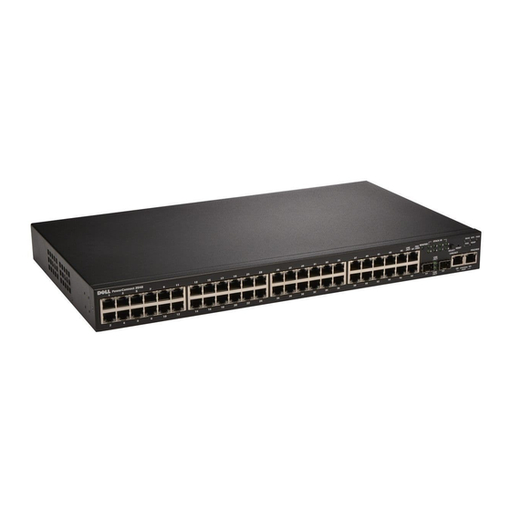
PowerConnect 3548 The PowerConnect 3548 provides 48 10/100Mbps ports plus two SFP ports, and two Copper ports which can be used to forward traffic in a stand-alone device, or as stacking ports when the device is stacked. The device also provides one RS-232 console port. The PowerConnect 3548 is a stackable device, but also functions as a stand-alone device. -
Page 13: Understanding The Stack Topology
Understanding the Stack Topology The PowerConnect 35xx series systems operates in a Ring topology. A stacked Ring topology is where all devices in the stack are connected to each other forming a circle. Each device in the stack accepts data and sends it to the device to which it is attached. -
Page 14: Removing And Replacing Stacking Members
The device units are shipped with a default Unit ID of the stand-alone unit. If the device is operating as a stand-alone unit, all stacking LEDs are off. Once the user selects a different Unit ID, it is not erased, and remains valid, even if the unit is reset. Unit ID 1 and Unit ID 2 are reserved for Master enabled units. -
Page 15: Exchanging Stacking Members
Each port in the stack has a specific Unit ID, port type, and port number, which are part of both the configuration commands and the configuration files. Configuration files are managed only from the device Stack Master, including: • Saving to the FLASH •... - Page 16 Figure 1-4. PowerConnect 3548/P replaces PowerConnect 3548/P Same Configuration Same Same Configuration Configuration • If a PowerConnect 3548/P replaces PowerConnect 3524/P, the first 3548/P 24 FE ports receive the 3524/P 24 FE port configuration. The GE port configurations remain the same. The remaining ports receive the default port configuration.
-
Page 17: Switching From The Stack Master To The Backup Stack Master
Figure 1-6. PowerConnect 3548/P port replaces PowerConect 3524/P Port Same Same Configuration Configuration Switching from the Stack Master to the Backup Stack Master The Backup Master replaces the Stack Master if the following events occur: • The Stack Master fails or is removed from the stack. •... -
Page 18: Head Of Line Blocking Prevention
• PDAs • Audio and video remote monitoring For more information about Power over Ethernet, see "Managing Power over Ethernet". Head of Line Blocking Prevention Head of Line (HOL) blocking results in traffic delays and frame loss caused by traffic competing for the same egress port resources. -
Page 19: Mac Address Supported Features
The PowerConnect 35xx series systems enhances auto negotiation by providing port advertisement. Port advertisement allows the system administrator to configure the port speeds that are advertised. For more information on auto-negotiation, see "Defining Port Configuration" or "Defining LAG Parameters." Voice VLAN Voice VLAN allows network administrators to enhance VoIP service by configuring ports to carry IP voice traffic from IP phones on a specific VLAN. -
Page 20: Layer 2 Features
VLAN-aware MAC-based Switching The device always performs VLAN-aware bridging. Classic bridging(IEEE802.1D) is not performed, where frames are forwarded based only on their destination MAC address. However, a similar functionality can be configured for untagged frames. Frames addressed to a destination MAC address that is not associated with any port are flooded to all ports of the relevant VLAN. -
Page 21: Vlan Supported Features
VLAN Supported Features VLAN Support VLANs are collections of switching ports that comprise a single broadcast domain. Packets are classified as belonging to a VLAN based on either the VLAN tag or based on a combination of the ingress port and packet contents. -
Page 22: Link Aggregation
Fast Link STP can take up to 30-60 seconds to converge. During this time, STP detects possible loops, allowing time for status changes to propagate and for relevant devices to respond. 30-60 seconds is considered too long of a response time for many applications. The Fast Link option bypasses this delay, and can be used in network topologies where forwarding loops do not occur. -
Page 23: Quality Of Service Features
BootP and DHCP Clients DHCP enables additional setup parameters to be received from a network server upon system startup. DHCP service is an on-going process. DHCP is an extension to BootP . For more information on DHCP , see "Defining DHCP IPv4 Interface Parameters." Quality of Service Features Class Of Service 802.1p Support The IEEE 802.1p signaling technique is an OSI Layer 2 standard for marking and prioritizing network... - Page 24 TFTP Trivial File Transfer Protocol The device supports boot image, software, and configuration upload/download via TFTP . Remote Monitoring Remote Monitoring (RMON) is an extension to SNMP , which provides comprehensive network traffic monitoring capabilities (as opposed to SNMP which allows network device management and monitoring).
-
Page 25: Security Features
802.1ab (LLDP-MED) The Link Layer Discovery Protocol (LLDP) allows network managers to troubleshoot and enhance network management by discovering and maintaining network topologies over multi-vendor environments. LLDP discovers network neighbors by standardizing methods for network devices to advertise themselves to other systems, and to store discovered information. The multiple advertisement sets are sent in the packet Type Length Value (TLV) field. -
Page 26: Additional Cli Documentation
Secure Shell (SSH) is a protocol that provides a secure, remote connection to a device. SSH version 2 is currently supported. The SSH server feature enables an SSH client to establish a secure, encrypted connection with a device. This connection provides functionality that is similar to an inbound telnet connection. -
Page 27: Hardware Description
Hardware Description Port Description PowerConnect 3524 Port Description The Dell™ PowerConnect™ 3524 device is configured with the following ports: • 24 Fast Ethernet ports — RJ-45 ports designated as 10/100Base-T ports • 2 Fiber ports — Designated as 1000Base-X SFP ports •... -
Page 28: The Back Panel Contains An Rps Connector, Console Port, And Power Connector
There are two buttons on the front panel. The Stack ID button is used to select the unit number. The second button is the Reset Button which is used to manually reset the device. The Reset button does not extend beyond the unit’s front panel surface, so reset by pressing it accidentally is prevented. On the front panel are all the device LEDs. -
Page 29: Sfp Ports
The front panel contains 48 RJ-45 ports number 1-48. The upper row of ports is marked by odd numbers 1-47, and the lower row of ports is marked with even numbers 2-48. In addition, the front panel also contains ports G1 - G2 which are fiber ports and ports G3- G4 which are copper ports. Ports G3- G4 can either be used as stacking ports, or used to forward network traffic in a stand-alone device. -
Page 30: Physical Dimensions
Physical Dimensions The PowerConnect 3524/P and PowerConnect 3548/P devices have the following physical dimensions: PoE Model: • Width — 440 mm (17.32 inch) • Depth — 387 mm (15.236 inch) • Height — 43.2 mm (1.7 inch) Non-PoE Device: • Width —... - Page 31 The following figure illustrates the 100 Base-T LEDs. Figure 2-7. RJ-45 1000 BaseT LED The RJ-45 LED indications for PowerConnect 3524 and PowerConnect 3548 are described in the following table: Table 2-1. PowerConnect 3524 and PowerConnect 3548 RJ-45 100BaseT LED Indications Color Description Link/Activity/Speed...
-
Page 32: Gigabit Port Leds
The RJ-45 LED indications for PowerConnect 3524P and PowerConnect 3548P are described in the following table: Table 2-2. PowerConnect 3524P and PowerConnect 3548P RJ-45 Copper based 100BaseT LED Indications Color Description Speed/Link/Act Green Static The port is currently linked at 100 Mbps. -
Page 33: System Leds
SFP LEDs The SFP ports each have one LED marked as LNK/ACT. On the PowerConnect 3524/P and PowerConnect 3548/P devices, the LEDs are located between ports and are round in shape. The following figures illustrate the LEDs on each device. Figure 2-8. - Page 34 The following table describes the system LED indications. Table 2-5. System LED Indicators Color Description Power Supply (PWR) Green Static The switch is turned on. The switch is turned off. Redundant Power Supply (RPS) Green Static The RPS is currently operating. (models: 3524 and 3548 ) Red Static The RPS failed.
-
Page 35: Power Supplies
The Stacking LEDs are numbered 1- 8. Each stacking unit has one stacking LED lit, indicating its Unit ID number. If either Stacking LED 1 or 2 is lit, it indicates that the device is either the Stack Master or Backup Master. -
Page 36: Stack Id Button
Figure 2-11. Power Connection When the device is connected to a different power source, the probability of failure in the event of a power outage decreases. Stack ID Button The device front panel contains a Stack ID button used to manually select the Unit ID for the Stack Master and members. -
Page 37: Reset Button
Reset Button The PowerConnect 3524/P and PowerConnect 3548/P switches have a reset button, located on the front panel, for manual reset of the device. If the Master device is reset, the entire stack is reset. If only a member unit is reset, the remain stacking members are not reset. The single reset circuit of the switch is activated by power-up or low-voltage conditions. - Page 38 Hardware Description...
-
Page 39: Installing The Powerconnect 3524/P And Powerconnect 3548/P
PowerConnect 3548/P Site Preparation The Dell™ PowerConnect™ 3524 /P and PowerConnect 3548/P devices can be mounted in a standard 48.26-am (19-inch) equipment rack, placed on a tabletop or mounted on a wall. Before installing the unit, verify that the chosen location for installation meets the following site requirements: •... -
Page 40: Unpacking The Device
• Rack-mount kit for rack installation or wall mounting kit • Documentation CD • Product Information Guide Unpacking the Device NOTE: Before unpacking the device, inspect the package and immediately report any evidence of damage. 1 Place the box on a clean flat surface. 2 Open the box or remove the box top. -
Page 41: Installing On A Flat Surface
1 Place the supplied rack-mounting bracket on one side of the device, ensuring that the mounting holes on the device line up to the mounting holes on the rack-mounting bracket. The following figure illustrates where to mount the brackets. Figure 3-1. Bracket Installation for Rack Mounting 2 Insert the supplied screws into the rack-mounting holes and tighten with a screwdriver. -
Page 42: Installing The Device On A Wall
Installing the Device on a Wall 1 Place the supplied wall-mounting bracket on one side of the device, ensuring that the mounting holes on the device line up to the mounting holes on the rack-mounting bracket. The following figure illustrates where to mount the brackets. Figure 3-2. -
Page 43: Connecting To A Terminal
Figure 3-3. Mounting a Device on a Wall Drilled Holes Wall Drilled Holes Front Panel Connecting to a Terminal 1 Connect an RS-232 crossover cable to the ASCII terminal or the serial connector of a desktop system running terminal emulation software. 2 Connect the female DB-9 connector at the other end of the cable to the device serial port connector. -
Page 44: Connecting A Device To A Power Supply
PowerConnect 3524/3548 Rear View Console Port EPS Connector Power Connector PowerConnect 3524P/3548P Rear View After connecting the device to a power source, confirm that the device is connected and operating correctly by examining the LEDs on the front panel. Installing a Stack Overview Each device can operate as a stand-alone device or can be a member in a stack. -
Page 45: Stacking Powerconnect 35Xx Series Systems Switches
Stacking PowerConnect 35xx Series Systems Switches Each PowerConnect 35xx series systems stack contains a single Master unit, and may have a Master Backup unit, while the remaining units are considered stacking Members. PowerConnect 35xx series systems switches use the RJ-45 Gigabit Ethernet ports (G3 and G4) for stacking. -
Page 46: Unit Id Selection Process
Figure 3-6. Stacking Configuration and Identification Panel Each stack device has a unique identifying unit ID that defines the unit’s position and function in the stack. If the device is a stand-alone unit, the Stack LED is not illuminated. The default setting is stand-alone. -
Page 47: Starting And Configuring The Device
Before proceeding, read the release notes for this product. Download the release notes from the Dell Support website at support.dell.com. NOTE: It is recommended that you obtain the most recent revision of the user documentation from the Dell Support website at support.dell.com. Connecting to the Device To configure the device, the device must be connected to a console. - Page 48 3 Set the data rate to 9600 baud. 4 Set the data format to 8 data bits, 1 stop bit, and no parity. 5 Set flow control to none. 6 Under Properties, select VT100 for Emulation mode. 7 Select Terminal keys for Function, Arrow, and Ctrl keys. Ensure that the setting is for Terminal keys (not Windows keys).
-
Page 49: Configuring Powerconnect 3524/P And 3548/P
The order of installation and configuration procedures is illustrated in the following figure: NOTE: Before proceeding, read the release notes for this product. Download the release notes from support.dell.com. Figure 4-1. Installation and Configuration Flow Hardware Connect Device and... -
Page 50: Booting The Switch
Before proceeding, read the release notes for this product. Download the release notes from the Dell Support website at support.dell.com. NOTE: The initial configuration assumes the following: • The Dell™ PowerConnect™ device was never configured before and is in the same state as when you received it. • The PowerConnect device booted successfully. •... - Page 51 You can exit the Setup Wizard at any time by entering [ctrl+z]. Wizard Step 1 The following is displayed: The system is not setup for SNMP management by default. To manage the switch using SNMP (required for Dell Network Manager) you can • Setup the initial SNMP version 2 account now.
- Page 52 [Privilege Level 15] to this account. You can use Dell Network Manager or CLI to change this setting, and to add additional management systems. For more information on adding management systems, see the user documentation.
- Page 53 Wizard Step 3 The following is displayed: Next, an IP address is setup. The IP address is defined on the default VLAN (VLAN #1), of which all ports are members. This is the IP address you use to access the CLI, Web interface, or SNMP interface for the switch.To setup an IP address: Please enter the IP address of the device (A.B.C.D):[1.1.1.1]...
-
Page 54: Advanced Configuration
Enter [Y] to complete the Setup Wizard. The following is displayed: Configuring SNMP management interface Configuring user account..Configuring IP and subnet..Thank you for using Dell Easy Setup Wizard. You will now enter CLI mode. Wizard Step 6 The CLI prompt is displayed. - Page 55 • Assigning Dynamic IP Addresses (on a VLAN): console# configure console(config)# interface ethernet vlan 1 console(config-if)# ip address dhcp hostname device console(config-if)# exit console(config)# The interface receives the IP address automatically. 3 To verify the IP address, enter the show ip interface command at the system prompt as shown in the following example.
-
Page 56: Receiving An Ip Address From A Bootp Server
Receiving an IP Address From a BOOTP Server The standard BOOTP protocol is supported and enables the device to automatically download its IP host configuration from any standard BOOTP server in the network. In this case, the device acts as a BOOTP client. - Page 57 Configuring Security Passwords The security passwords can be configured for the following services: • Terminal • Telnet • • HTTP • HTTPS NOTE: Passwords are user-defined. NOTE: When creating a user name, the default priority is 1, which allows access but not configuration rights. A priority of 15 must be set to enable access and configuration rights to the device.
- Page 58 console(config-line)# enable authentication default console(config-line)# password bob • When initially logging onto a device through a Telnet session, enter bob at the password prompt. • When changing a device mode to enable, enter bob. Configuring an Initial SSH password To configure an initial SSH password, enter the following commands: console(config)# aaa authentication login default line console(config)# aaa authentication enable default line console(config)# line ssh...
-
Page 59: Configuring Login Banners
Configuring Login Banners You can define 3 types of login banners: • Message-of-the-Day Banner: Displayed when the user is connected to the device, before the user has logged in. • Login Banner: Displayed after the Message-of-the-Day Banner, and before the user has logged in. •... - Page 60 Ryan board, based on PPC8247 128 MByte SDRAM. I-Cache 16 KB. D-Cache 16 KB. Cache Enabled. Autoboot in 2 seconds - press RETURN or Esc. to abort and enter prom. 2 When the auto-boot message appears, press <Enter> to get the Startup menu. The Startup menu procedures can be done using the ASCII terminal or Windows HyperTerminal.
- Page 61 Flash size is: 16M 01-Jan-xxxx 01:01:07 %CDB-I-LOADCONFIG: Loading running configuration. 01-Jan-xxxx 01:01:07 %CDB-I-LOADCONFIG: Loading startup configuration. Device configuration: CPLD revision: 1.01 Slot 1 - PowerConnect 35xx HW Rev. ------------------------------------ -- Unit Standalone ------------------------------------ Tapi Version: v1.3.3.1 Core Version: v1.3.3.1 01-Jan-xxxx 01:01:19 %INIT-I-InitCompleted: Initialization task is completed 01-Jan-xxxx 01:01:19 %SNMP-I-CDBITEMSNUM: Number of running configuration items loaded: 0...
- Page 62 Erase FLASH File - option[2] In some cases, the device configuration must be erased. If the configuration is erased, all parameters configured via CLI, EWS or SNMP must be reconfigured. To erase the device configuration: 1 From the Startup menu, press [2] within two seconds to erase flash file. The following message is displayed: Warning! About to erase a Flash file.
-
Page 63: Software Download Through Tftp Server
Software Download Through TFTP Server This section contains instructions for downloading device software (system and boot images) through a TFTP server. The TFTP server must be configured before downloading the software. System Image Download The device boots and runs when decompressing the system image from the flash memory area where a copy of the system image is stored. - Page 64 5 Enter the copy tftp://{tftp address}/{file name} image command to copy a new system image to the device. When the new image is downloaded, it is saved in the area allocated for the other copy of system image (image-2, as given in the example). The following is an example of the information that appears: console# copy tftp://176.215.31.3/file1.ros image Accessing file ‘file1’...
- Page 65 Boot Image Download Loading a new boot image from the TFTP server and programming it into the flash updates the boot image. The boot image is loaded when the device is powered on. A user has no control over the boot image copies.
-
Page 66: Port Default Settings
Port Default Settings The general information for configuring the device ports includes the short description of the auto-negotiation mechanism and the default settings for switching ports. Auto-Negotiation Auto-negotiation enables automatic detection of speed, duplex mode and flow control on all switching 10/100/1000BaseT ports. -
Page 67: Switching Port Default Settings
Switching Port Default Settings The following table gives the port default settings. Table 4-1. Port Default Settings Function Default Setting Port speed and mode 10/100BaseT copper: auto-negotiation 100 Mbps full duplex 10/100/1000BaseT copper / SFP: auto-negotiation1000 Mbps full duplex Port forwarding state Enabled Port tagging No tagging Flow Control... - Page 68 Configuring PowerConnect 3524/P and 3548/P...
-
Page 69: Using Dell Openmanage Switch Administrator
Using Dell OpenManage Switch Administrator This section provides an introduction to the Dell™ OpenManage™ Switch Administrator user interface. Starting the Application NOTE: Before starting the application the IP address must be defined. For more information, see Initial Configuration. 1 Open a web browser. - Page 70 The components list contains a list of the feature components. Components can also be viewed by expanding a feature in the tree view. The information buttons provide access to information about the device and access to Dell Support. For more information, see "Information Buttons." Using Dell OpenManage Switch Administrator...
-
Page 71: Device Representation
Device Representation The home page contains a graphical representation of the device front panel. Figure 5-2. Dell PowerConnect™ Device Port Indicators The port coloring indicates if a specific port is currently active. Ports can be the following colors: Table 5-2. PowerConnect Port and Stacking Indicators... -
Page 72: Using The Switch Administrator Buttons
The online help pages are context-sensitive. For example, if the IP Addressing page is open, the help topic for that page displays when Help is clicked. About Contains the version and build number and Dell copyright information. Log Out Opens the Log Out window. -
Page 73: Field Definitions
4 When finished, enter the exit Privileged EXEC mode command. The session quits. NOTE: If a different user logs into the system in the Privileged EXEC command mode, the current user is logged off and the new user is logged in. Using Dell OpenManage Switch Administrator... -
Page 74: Telnet Connection
The Global Configuration mode manages the device configuration on a global level. The Interface Configuration mode configures the device at the physical interface level. Interface commands which require subcommands have another level called the Subinterface Configuration mode. A password is not required. Using Dell OpenManage Switch Administrator... -
Page 75: User Exec Mode
Enter Password: ****** console# console# disable console> Use the exit command to move back to a previous mode. For example, from Interface Configuration mode to Global Configuration mode, and from Global Configuration mode to Privileged EXEC mode. Using Dell OpenManage Switch Administrator... -
Page 76: Global Configuration Mode
The following example illustrates how to access Global Configuration mode and return back to the Privileged EXEC mode: console# console# configure console(config)# exit console# For a complete list of the CLI modes, see the Dell™ PowerConnect™3524/P and PowerConnect 3548/P CLI Guide. Using Dell OpenManage Switch Administrator... -
Page 77: Configuring System Information
Configuring System Information This section provides information This page provides links for defining system parameters including security features, downloading switch software, and resetting the switch. To open the System page, Click a link below to access on-line help for the indicated screen. Click System in the tree view. -
Page 78: Defining General Switch Information
• "Managing Management Security" on page 170 • "Configuring LLDP and MED" on page 205 • "Defining SNMP Parameters" on page 219 • "Managing Files" on page 246 • "Configuring Advanced Settings" on page 259 Defining General Switch Information The General page contains links to pages that allow network managers to configure switch parameters. This section contians the following topics: •... - Page 79 Figure 6-2. Asset The Asset page contains the following fields: • System Name (0-159 Characters) — Defines the user-defined device name. • System Contact (0-159 Characters) — Indicates the name of the contact person. • System Location (0-159 Characters) — The location where the system is currently running. •...
- Page 80 • Unit No. — Indicates the unit number for which the device asset information is displayed. • Service Tag — The service reference number used when servicing the device. • Asset Tag (0-16 Characters) — Indicates the user-defined device reference. •...
- Page 81 The following is an example of defining the device host name, system contact and device location as well as setting the time and date of the system clock using the CLI commands: console(config)# hostname dell dell (config)# snmp-server contact Dell_Tech_Supp dell (config)# snmp-server location New_York dell (config)# exit Console(config)# snmp-server host 10.1.1.1 management 2...
- Page 82 89788981 893658976 mkt-5 89788982 893658977 mkt-6 89788983 893658978 mkt-7 89788984 893658979 mkt-8 89788985 console# show system Unit Type ---- ----------------- PowerConnect 3524 PowerConnect 3524 PowerConnect 3524 PowerConnect 3524P PowerConnect 3524P PowerConnect 3524P PowerConnect 3524P PowerConnect 3524P Configuring System Information...
- Page 83 Unit Main Power Supply Redundant Power Supply ---- ----------------- ---------------------- Unit Fan1 Fan2 Fan3 Fan4 Fan5 ---- ---- ---- ---- ---- ---- Unit Temperature (Celsius) Temperature Sensor Status ---- -------------------- ------------------------- Configuring System Information...
-
Page 84: Defining System Time Settings
Defining System Time Settings The Time Synchronization page contains fields for defining system time parameters for both the local hardware clock, and the external SNTP clock. If the system time is kept using an external SNTP clock, and the external SNTP clock fails, and the system time reverts to the local hardware clock. Daylight Savings Time can be enabled on the device. - Page 85 • Ireland — Last weekend of March until the last weekend of October. • Israel — Varies year-to-year. • Italy — Last weekend of March until the last weekend of October. • Japan — Japan does not operate Daylight Saving Time. •...
- Page 86 For more information on SNTP , see "Configuring SNTP Settings" on page 104. → → To open the Time Synchronization page, click System General Time Synchronization in the tree view. Figure 6-3. Time Synchronization The Time Synchronization page contains the following fields: •...
- Page 87 There are two types of daylight settings, either by a specific date in a particular year or a recurring setting irrespective of the year. For a specific setting in a particular year complete the Daylight Savings area, and for a recurring setting, complete the Recurring area. •...
- Page 88 • From — Defines the time that DST begins each year. For example, DST begins locally every second Sunday in April at 5:00 am. The possible field values are: – Day — The day of the week from which DST begins every year. The possible field range is Sunday-Saturday.
- Page 89 The following steps must be completed before setting the summer clock: 1 Configure the summer time. 2 Define the time zone. 3 Set the clock. For example: console(config)# clock summer-time recurring usa console(config)# clock time zone 2 zone TMZ2 console(config)# clock set 10:00:00 apr 15 2004 Table 6-2.
-
Page 90: Viewing System Health Information
Viewing System Health Information The System Health page displays physical device information, including information about the device’s → → power and ventilation sources. To open the System Health page, click System General Health in the tree view. Figure 6-4. System Health The System Health page contains the following fields: •... - Page 91 Table 6-3. Celsius to Fahrenheit Conversion Table Celsius Fahrenheit Viewing System Health Information Using the CLI Commands The following table summarizes the equivalent CLI commands for viewing fields displayed on the System Health page. Table 6-4. System Health CLI Command CLI Command Description Displays system information.
-
Page 92: Managing Power Over Ethernet
Powered Devices are devices which receive power from the PowerConnect power supplies, for example IP phones. Powered Devices are connected to the PowerConnect device via Ethernet ports. Powered devices are connected via either all PowerConnect 3524P’s 24 FE ports or all PowerConnect 3548P’s 48 FE ports. - Page 93 Figure 6-5. Power Over Ethernet The Power Over Ethernet page contains the following sections: • Global • Port Settings Configuring System Information...
- Page 94 Global The Power over Ethernet Global Settings section contains the following fields: • Power Status — Indicates the inline power source status. – On — Indicates that the power supply unit is functioning. – Off — Indicates that the power supply unit is not functioning. –...
- Page 95 – Test — Indicates the powered device is being tested. For example, a powered device is tested to confirm it is receiving power from the power supply. – Other Fault — – Unknown — • Power Priority Level Determines the port priority if the power supply is low. The port power —...
- Page 96 Defining PoE Settings 1 Open the Power Over Ethernet page. 2 Define the fields. 3 Click Apply Changes. PoE settings are defined, and the device is updated. Displaying PoE Settings for All Ports 1 Open the Power Over Ethernet page. 2 Click Show All.
- Page 97 The following is an example of the PoE CLI commands. Console> enable Console# show power inline Unit Power Nominal Power Consumed Power Usage Threshold 370 Watts 0 Watts (0%) Disable 1 Watts 0 Watts (0%) Disable 1 Watts 0 Watts (0%) Disable 1 Watts 0 Watts (0%)
-
Page 98: Viewing Version Information
Viewing Version Information The Versions page contains information about the hardware and software versions currently running. To open the Versions page, click System → General → Versions in the tree view. Figure 6-7. Versions The Versions page contains the following fields: •... -
Page 99: Managing Stack Members
Displaying Device Versions Using the CLI The following table summarizes the equivalent CLI commands for viewing fields displayed in the Versions page. Table 6-6. Versions CLI Commands CLI Command Description Displays system version information. show version The following is an example of the CLI commands: console>... -
Page 100: Resetting The Device
Switching Between Stack Masters 1 Open the Stack Management page. 2 Check the Switch Stack Control from Unit 1 to Unit 2 check box. 3 Click Apply Changes. A confirmation message displays. 4 Click OK. The device is reset. After the device is reset, a prompt for a user name and password displays. Managing Stacks Using the CLI Commands The following table summarizes the equivalent CLI commands for viewing fields displayed in the Stack Management page. -
Page 101: Configuring Sntp Settings
Resetting the Device 1 Open the Reset page. 2 Select a unit in the Reset Unit Number field. 3 Click Apply Changes. A confirmation message displays. 4 Click OK. The device is reset. After the device is reset, a prompt for a user name and password is displayed. 5 Enter a user name and password to reconnect to the Web Interface. - Page 102 Time sources are established by Stratums. Stratums define the accuracy of the reference clock. The higher the stratum (where zero is the highest), the more accurate the clock. The switch receives time from stratum 1 and above. The following is an example of stratums: •...
-
Page 103: Defining Sntp Global Settings
The device retrieves synchronization information, either by actively requesting information or at every poll interval. If Unicast, Anycast and Broadcast polling are enabled, the information is retrieved in this order: • Information from servers defined on the device is preferred. If Unicast polling is not enabled or if no servers are defined on the device, the device accepts time information from any SNTP server that responds. - Page 104 The SNTP Global Settings page contains the following fields: • Poll Interval (60-86400) — Defines the interval (in seconds) at which the SNTP server is polled for Unicast information. By default, the poll interval is 1024 seconds. • Receive Broadcast Servers Updates — Listens to the SNTP servers for Broadcast server time information on the selected interfaces, when enabled.
-
Page 105: Defining Sntp Authentication Methods
Defining SNTP Authentication Methods The SNTP Authentication page enables SNTP authentication between the device and an SNTP server. The means by which the SNTP server is authenticated is also selected in the SNTP Authentication page. Click System → SNTP → Authentication in the tree view to open the SNTP Authentication page. Figure 6-11. - Page 106 Adding an SNTP Authentication Key 1 Open the SNTP Authentication page. 2 Click Add. The Add Authentication Key page opens. Figure 6-12. Add Authentication Key 3 Define the fields. 4 Click Apply Changes. The SNMP authentication key is added, and the device is updated. Displaying the Authentication Key Table 1 Open the SNTP Authentication page.
-
Page 107: Defining Sntp Servers
Deleting the Authentication Key 1 Open the SNTP Authentication page. 2 Click Show All. The Authentication Key Table opens. 3 Select an Authentication Key Table entry. 4 Select the Remove check box. 5 Click Apply Changes. The entry is removed, and the device is updated. Defining SNTP Authentication Settings Using CLI Commands The following table summarizes the equivalent CLI commands for setting fields displayed in the SNTP Authentication page. - Page 108 Figure 6-14. SNTP Servers The SNTP Servers page contains the following fields: • SNTP Server — Select a user-defined SNTP server IP address. Up to eight SNTP servers can be defined. • Poll Interval — Polls the selected SNTP Server for system time information, when enabled. •...
- Page 109 • Offset (msec) — Timestamp difference between the device local clock and the acquired time from the SNTP server. • Delay (msec) — The amount of time it takes to reach the SNTP server. • Remove — Removes a specific SNTP server from the SNTP Servers list. –...
- Page 110 3 Define the fields. 4 Click Apply Changes. The SNTP Server is added, and the device is updated. Displaying the SNTP Server Table 1 Open the SNTP Servers page. 2 Click Show All. The SNTP Servers Table opens. Figure 6-16. SNTP Servers Table Modifying an SNTP Server 1 Open the SNTP Servers page.
-
Page 111: Defining Sntp Interfaces
Defining SNTP Servers Settings Using CLI Commands The following table summarizes the equivalent CLI commands for setting fields displayed in the SNTP Server page. Table 6-11. SNTP Server CLI Commands CLI Command Description sntp server ipv4-address|ipv6- Configures the device to use SNTP to request and accept SNTP address|hostname [poll] [key keyid] traffic from a server. - Page 112 The SNTP Broadcast Interface Table page contains the following fields: • Unit No. — Indicates the stacking member on which the SNTP interface is enabled. Interface — Contains an interface list on which SNTP can be enabled: • Receive Servers Updates — Enables or disables SNTP on the specific interface. –...
-
Page 113: Managing Logs
The following is an example of the CLI commands for displaying SNTP interfaces: console# show sntp configuration Polling interval: 7200 seconds. MD5 Authentication keys: 8, 9 Authentication is required for synchronization. Trusted Keys: 8,9 Unicast Clients Polling: Enabled. Server Polling Encryption Key ----------- --------... -
Page 114: Defining Global Log Parameters
A system warning has occurred. Notice The system is functioning properly, but system notice has occurred. Informational Provides device information. Debug Provides detailed information about the log. If a Debug error occurs, contact Dell Online Technical Support. Configuring System Information... - Page 115 The Logs - Global Parameters page contains fields for defining which events are recorded to which logs. It contains fields for enabling logs globally, and fields for defining log parameters. The Severity log messages are listed from the highest severity to the lowest. →...
- Page 116 • Log Management Access Events — Enables or disables generating logs when the device is accessed using a management method. For example, each time the device is accessed using SSH, a device log is generated. • Severity — Displays the severity logs. The following are the severity log levels. When a severity level is selected, all severity level choices above the selection are selected automatically.
- Page 117 Table 6-14. Global Log Parameters CLI Commands CLI Command Description logging on Enables error message logging. logging { ipv4-address | ipv6-address | hostname} Logs messages to a syslog server. For a list of the Severity levels, [port port] [severity level] [facility facility] see "Log Severity Levels"...
-
Page 118: Viewing The Ram Log Table
Viewing the RAM Log Table The RAM Log Table contains information about log entries kept in RAM, including the time the log was → entered, the log severity, and a description of the log. To open the RAM Log Table, click System Logs →... - Page 119 The following is an example of the CLI commands: console# show logging Logging is enabled. Console Logging: Level info. Console Messages: 0 Dropped. Buffer Logging: Level info. Buffer Messages: 124 Logged, 124 Displayed, 200 Max. File Logging: Level error. File Messages: 164 Logged, 126 Dropped.
-
Page 120: Viewing The Log File Table
Viewing the Log File Table The Log File Table contains information about log entries saved to the Log File in FLASH, including the time the log was entered, the log severity, and a description of the log message. To open the Log File →... -
Page 121: Viewing The Device Login History
The following is an example of the CLI commands: console# show logging file Logging is enabled. Console Logging: Level info. Console Messages: 0 Dropped. Buffer Logging: Level info. Buffer Messages: 62 Logged, 62 Displayed, 200 Max. File Logging: Level debug. File Messages: 11 Logged, 51 Dropped. - Page 122 Figure 6-22. Login History The Login History page contains the following fields: • User Name — Contains a user-defined device user name list. • Login History — Indicates if the Login History logs are enabled. • Login Time — Indicates the time the selected user logged on to the device. •...
-
Page 123: Modifying Remote Log Server Definitions
Displaying the Device Login History Using CLI Commands The following table summarizes the equivalent CLI commands for viewing and setting fields displayed in the Login History page. Table 6-17. Log File Table CLI Commands CLI Command Description show users login-history Displays password management history information. - Page 124 Figure 6-23. Remote Log Server Settings The Remote Log Server Settings page contains the following fields: • Available Servers — Contains a list of servers to which logs can be sent. • UDP Port (1-65535) — The UDP port to which the logs are sent for the selected server. The possible range is 1 - 65535.
- Page 125 • Severity to Include — The following are the available severity levels: – Emergency —The system is not functioning. – Alert — The system needs immediate attention. – Critical — The system is in a critical state. – Error — A system error has occurred. –...
- Page 126 Defining a New Server: 1 Open the Remote Log Server Settings page. 2 Click Add. The Add a Log Server page opens. Figure 6-24. Add a Log Server The Add a Log Server page contains the additional field: – New Log Server IP Address — Defines the IP address of the new Log Server. 3 Define the fields.
- Page 127 Displaying the Remote Log Servers Table: 1 Open the Remote Log Server Settings page. 2 Click Show All. The Log Servers Table page opens. Figure 6-25. Log Servers Table Removing a Log Server from the Log Servers Table Page: 1 Open the Remote Log Server Settings page. 2 Click Show All.
-
Page 128: Defining Ip Addressing
The following is an example of the CLI commands: console> enable console# configure console(config)# logging 10.1.1.1 severity critical console(config)# end console# show logging Logging is enabled. Console Logging: Level debug. Console Messages: 5 Dropped. Buffer Logging: Level debug. Buffer Messages: 16 Logged, 16 Displayed, 200 Max. -
Page 129: Configuring The Internet Protocol Version 6 (Ipv6)
• "Defining Default Domains" on page 157 • "Mapping Domain Host" on page 159 • "Defining ARP Settings" on page 162 Configuring the Internet Protocol Version 6 (IPv6) The device functions as an IPv6 compliant Host, as well as an IPv4 Host (also known as dual stack). This allows device operation in a pure IPv6 network as well as in a combined IPv4/IPv6 network. - Page 130 Figure 6-26. IPv4 Default Gateway The IPv4 Default Gateway page contains the following fields: • User Defined — The device’s Gateway IP address. • Active — Indicates if the Gateway is active. • Remove User Defined — Removes the default gateway. The possible field values are: –...
-
Page 131: Defining Ipv4 Interfaces
Defining a Device’s IPv4 Gateway Using the CLI Commands The following table summarizes the equivalent CLI commands for setting fields displayed in the Default Gateway page Table 6-19. Default Gateway CLI Commands CLI Command Description ip default-gateway ip-address Defines a default gateway. no ip default-gateway Removes a default gateway. - Page 132 The IP Interface Parameters page contains the following parameters: • IP Address — The interface IP address. • Prefix Length — The number of bits that comprise the IP address prefix. • Interface — The interface type for which the IP address is defined. Select Port, LAG, or VLAN. •...
- Page 133 3 Modify the interface type. 4 Click Apply Changes. The parameters are modified, and the device is updated. Deleting IPv4 Addresses 1 Open the IPv4 Interface Parameters page. 2 Click Show All. The Interface Parameters Table page opens. Figure 6-29. IPv4 Interface Parameter Table 3 Select an IP address and select the Remove check box.
-
Page 134: Defining Dhcp Ipv4 Interface Parameters
The following is an example of the CLI commands: console(config)# interface vlan 1 console(config-if)# ip address 92.168.1.123 255.255.255.0 console(config-if)# no ip address 92.168.1.123 console(config-if)# end console# show ip interface vlan 1 Gateway IP Address Activity status --------------------------------------- 192.168.1.1 Active IP address Interface Type -------------------------------------------------... - Page 135 The DHCP IP Interface page contains the following fields: • Interface — The DHCP client interface. Click the option button next to Port, LAG, or VLAN and select the DHCP client interface. • Host Name — The system name as written in a DHCP Server log. This field can contain up to 20 characters.
- Page 136 Deleting a DHCP IPv4 Interface 1 Open the DHCP IPv4 Interface page. 2 Click Show All. The DHCP IPv4 Interface Table opens. IPv4 Figure 6-32. DHCP Interface Table 3 Select a DHCP client entry. 4 Select the Remove check box. 5 Click Apply Changes.
-
Page 137: Defining Ipv6 Interfaces
Defining IPv6 Interfaces The system supports IPv6 hosts. The IPv6 Interface page contains fields for defining IPv6 interfaces. → → To open the IPv6 Interface page, click System IP Addressing IPv6 Interface in the tree view. Figure 6-33. IPv6 Interface •... - Page 138 • Autoconfiguration — Specifies whether IPv6 address assignment on an interface is done by stateless autoconfiguration. When enabled, the router solicitation ND procedure is initiated (to discover a router in order to assign an IP address to the interface based on prefixes received with RA messages). When autoconfiguration is disabled, no automatic assignment of IPv6 Global Unicast addresses is performed, and existing automatically assigned IPv6 Global Unicast addresses are removed from the interface.
- Page 139 • IPv6 Address Origin Type — Defines the type of configurable static IPv6 address for an interface. The possible values are: – Dyanmic — Indicates the IP address was received from RA. – Static — Indicates the IP address was configured by the user. –...
- Page 140 Adding an IPv6 Address to the Current Interface 1 Open the IPv6 Interface page. 2 Click Add IPv6 Address. The Add IPv6 Address page opens. Figure 6-35. Add IPv6 Address 3 Complete the fields on the page. 4 Click Apply Changes. The new address is added, and the device is updated.
- Page 141 Defining IPv6 Interfaces Using CLI Commands The following table summarizes the equivalent CLI commands for setting fields displayed in the IPv6 Interface page. Table 6-22. IPv6 Interface CLI Commands CLI Command Description ipv6 enable [no-autoconfig] Enables IPv6 processing on an interface. ipv6 address autoconfig Enables automatic configuration of IPv6 addresses using stateless auto-configuration on an interface.
-
Page 142: Defining Ipv6 Default Gateway
The following is an example of the CLI commands: console# show ipv6 interface vlan 1 Number of ND DAD attempts: 1 MTU size: 1500 Stateless Address Autoconfiguration state: enabled ICMP unreachable message state: enabled MLD version: 2 IP addresses Type DAD State ------------------------ ------ -----------... - Page 143 → → To open the IPv6 Default Gateway page, click System IP Addressing IPv6 Default Gateway in the tree view. Figure 6-36. IPv6 Default Gateway • Default Gateway IP Address — Displays the Link Local IPv6 address of the default gateway. •...
- Page 144 • State — Displays the default gateway status. The possible field values are: – Incomplete — Indicates that address resolution is in progress and the link-layer address of the default gateway has not yet been determined. – Reachable — Indicates that the default gateway is known to have been reachable recently (within tens of seconds ago).
-
Page 145: Defining Ipv6 Isatap Tunnels
Defining IPv6 Default Gateway Parameters Using CLI Commands The following table summarizes the equivalent CLI commands for setting fields displayed in the IPv6 Default Gateway page. Table 6-23. IPv6 Default Gateway CLI Commands CLI Command Description ipv6 default-gateway ipv6- Defines an IPv6 default gateway. address Defining IPv6 ISATAP Tunnels The IPv6 ISATAP Tunnel Page defines the tunneling process on the device, which encapsulates... - Page 146 → → To open the IPv6 ISATAP Tunnel page, click System IP Addressing IPv6 ISATAP Tunnel in the tree view. Figure 6-38. IPv6 ISATAP Tunnel • ISATAP Status — Specifies the status of ISATAP on the device. The possible field values are: –...
- Page 147 Defining IPv6 ISATAP Tunnel Parameters Using CLI Commands The following table summarizes the equivalent CLI commands for setting fields displayed in the IPv6 ISATAP Tunnel page. Table 6-24. IPv6 Default Gateway CLI Commands CLI Command Description interface tunnel number Enters tunnel interface configuration mode. tunnel mode ipv6ip {isatap} Configures an IPv6 transition mechanism global support mode.
-
Page 148: Defining Ipv6 Neighbors
Defining IPv6 Neighbors The IPv6 Neighbors Page contains information for defining IPv6 Neighbors which is similar to the functionality of the IPv4 Address Resolution Protocol (ARP). IPv6 Neighbors enables detecting Link Local addresses within the same subnet, and includes a database for maintaining reachability information about the active neighbors paths. - Page 149 • Type — Displays the type of the neighbor discovery cache information entry. The possible field values are: – Static — Shows static neighbor discovery cache entries. If an entry for the specified IPv6 address already exists in the neighbor discovery cache—as learned through the IPv6 neighbor discovery process—you can convert the entry to a static entry.
- Page 150 3 Complete the fields on the page. 4 Click Apply Changes. The new neighbor is added, and the device is updated. Modifying Neighbor Parameters 1 Open the IPv6 Neighbors page. 2 Select an IP address in the IPv6 Address drop-down menu. 3 Modify the required fields.
- Page 151 3 Select the Remove check box in the desired entry. Alternatively, select the desired value in the Clear Table field. The possible filed values are: – Static Only — Clears the the IPv6 Neighbor Table static entries. – Dynamic Only — Clears the IPv6 Neighbor Table dynamic entries. –...
-
Page 152: Viewing The Ipv6 Routes Table
Viewing the IPv6 Routes Table The IPv6 Routes Table stores information about IPv6 destination prefixes and how they are reached, either directly or indirectly. The routing table is used to determine the next-hop address and the interface used for forwarding. Each dynamic entry also has an associated invalidation timer value (extracted from Router Advertisements) used to delete entries that are no longer advertised. - Page 153 Viewing IPv6 Routes Table Parameters Using CLI Commands The following table summarizes the equivalent CLI commands for setting fields displayed in the IPv6 Routes Table page. Table 6-26. IPv6 Default Gateway CLI Commands CLI Command Description size traceroute {ipv4-address | hostname} [ packet_size] [ Discovers the routes that IPv4 packets will max-ttl] [count packet_count] [timeout time_out] [source...
-
Page 154: Configuring Domain Name Systems
Configuring Domain Name Systems Domain Name System (DNS) converts user-defined domain names into IP addresses. Each time a domain name is assigned the DNS service translates the name into a numeric IP address. For example, www.ipexample.com is translated into 192.87.56.2. DNS servers maintain domain name databases and their corresponding IP addresses. - Page 155 When defining a new DNS server, the following additional parameters are available: • Supported IP Format — Specifies the IP format supported by the server. The possible values are: – IPv6 — IP version 6 is supported. – IPv4 — IP version 4 is supported. •...
- Page 156 Displaying the DNS Servers Table 1 Open the Domain Naming System (DNS) page. 2 Click Show All. The DNS Server Table opens. Figure 6-45. DNS Server Table Removing DNS Servers 1 Open the Domain Naming System (DNS) page. 2 Click Show All. The DNS Server Table page opens.
-
Page 157: Defining Default Domains
Configuring DNS Servers Using the CLI Commands The following table summarizes the CLI commands for configuring device system information. Table 6-27. DNS Server CLI Commands CLI Command Description ip name-server server-address Sets the available name servers. Up to eight name servers can be set. no ip name-server server-address Removes a name server. - Page 158 [name] Displays the default domain name, list of name server hosts, the static and the cached list of host names and addresses. The following is an example of the CLI commands: console(config)# ip domain-name dell.com Configuring System Information...
-
Page 159: Mapping Domain Host
Mapping Domain Host The Host Name Mapping page provides parameters for assigning IP addresses to static host names. On this page, one IP address per host can be assigned. To open the Host Name Mapping page, click System → IP Addressing → Host Name Mapping in the tree view. - Page 160 When defining a new host name mapping, the following additional parameters are available: • Supported IP Format — Specifies the IP format supported by the host. The possible values are: – IPv6 — IP version 6 is supported. – IPv4 — IP version 4 is supported. •...
- Page 161 Displaying the Hosts Name Mapping Table 1 Open the Host Name Mapping page. 2 Click Show All. The Hosts Name Mapping Table page opens. Figure 6-49. Hosts Name Mapping Table Removing Host Name from IP Address Mapping 1 Open the Host Name Mapping page. 2 Click Show All.
-
Page 162: Defining Arp Settings
The following is an example of the CLI commands: console(config)# ip host accounting.abc.com 176.10.23.1 Defining ARP Settings The Address Resolution Protocol (ARP) converts IP addresses into physical addresses, and maps the IP address to a MAC address. ARP allows a host to communicate with other hosts only when the IP address of its neighbors is known. - Page 163 The ARP Settings page contains the following fields: • Global Settings — Select this option to activate the fields for ARP global settings. • ARP Entry Age Out (1-40000000) — For all devices, the amount of time (seconds) that passes between ARP requests about an ARP table entry.
- Page 164 Deleting ARP Table Entry 1 Open the ARP Settings page 2 Click Show All. The ARP Table page opens. 3 Select a table entry. 4 Select the Remove check box. 5 Click Apply Changes. The selected ARP Table entry is deleted, and the device is updated. Configuring ARP Using the CLI Commands The following table summarizes the equivalent CLI commands for setting fields displayed in the ARP Settings page.
-
Page 165: Running Cable Diagnostics
Running Cable Diagnostics The Diagnostics page contains links to pages for performing virtual cable tests on copper and fiber optic cables. To open the Diagnostics page, click System→ Diagnostics in the tree view. This section contians the following topics: • "Viewing Copper Cable Diagnostics"... - Page 166 The Integrated Cable Test for Copper Cables page contains the following fields: • Port — The port to which the cable is connected. • Test Result — The cable test results. The possible field values are: – No Cable — There is no cable connected to the port. –...
-
Page 167: Viewing Optical Transceiver Diagnostics
In addition to the fields in the Integrated Cable Test for Copper Cables page, the Integrated Cable Test Results Table contains the following field: • Unit No. — The stacking member unit for which the cable is displayed. Performing Copper Cable Tests Using CLI Commands The following table contains the CLI commands for performing copper cable tests. - Page 168 Figure 6-53. Optical Transceiver Diagnostics The Optical Transceiver Diagnostics page contains the following fields: • Port — The port number on which the cable is tested. • Temperature — The temperature (C) at which the cable is operating. • Voltage — The voltage at which the cable is operating. •...
- Page 169 Figure 6-54. Optical Transceiver Diagnostics Table In addition to the fields in the Optical Transceiver Diagnostics page, the Optical Transceiver Diagnostics Table contains the following field: • Unit No. — The unit number for which the cable is displayed. • N/A —...
-
Page 170: Managing Management Security
Managing Management Security The Management Security page provides access to security pages that contain fields for setting security parameters for device management methods, user authentication databases and servers. To open the Management Security page, click System→ Management Security in the tree view. This section contians the following topics: •... - Page 171 To open the Access Profiles page, click System → Management Security → Access Profiles in the tree view. Figure 6-55. Access Profiles The Access Profiles page contains following fields: • Access Profile — User-defined Access Profile lists. The Access Profile list contains a default value of Console Only.
- Page 172 Adding an Access Profile Rules act as filters for determining rule priority, the device management method, interface type, source IP address and network mask, and the device management access action. Users can be blocked or permitted management access. Rule priority sets the order in which the rules are implemented. Assigning an access profile to an interface denies access via other interfaces.
- Page 173 • Management Method — The management method for which the access profile is defined. Users with this access profile are denied or permitted access to the device from the selected management method (line). The possible field values are: – All — Assigns all management methods to the rule. –...
- Page 174 3 Define the Access Profile Name field. 4 Define the relevant fields. 5 Click Apply Changes. The new Access Profile is added, and the device is updated. Adding Rules to Access Profile The first rule must be defined to beginning matching traffic to access profiles. 1 Open the Access Profile page.
- Page 175 Viewing the Profile Rules Table The order in which rules appear in the Profile Rules Table is important. Packets are matched to the first rule which meets the rule criteria. 1 Open the Access Profiles page. 2 Click Show All. The Profile Rules Table page opens.
- Page 176 Defining Access Profiles Using CLI Commands The following table summarizes the equivalent CLI commands for setting fields displayed in the Access Profiles page. Table 6-33. Access Profiles CLI Commands CLI Command Description management access-list name Defines an access-list for management, and enters the access-list context for configuration.
-
Page 177: Defining Authentication Profiles
The following is an example of the CLI commands: console(config)# management access-list mlist console(config-macl)# permit ethernet 1/e1 console(config-macl)# permit ethernet 1/e2 console(config-macl)# deny ethernet 1/e3 console(config-macl)# deny ethernet 1/e4 console(config-macl)# exit console(config)# management access-class mlist console(config)# exit console# show management access-list mlist ----- permit ethernet 1/e1... - Page 178 If an error occurs during the authentication, the next selected method is used. To open the Authentication Profiles page, click System → Management Security → Authentication Profiles in the tree view. Figure 6-59. Authentication Profiles The Authentication Profiles page contains the following fields: •...
- Page 179 Selecting an Authentication Profile: 1 Open the Authentication Profiles page. 2 Select a profile in the Authentication Profile Name field. 3 Select the authentication method using the navigation arrows. The authentication occurs in the order the authentication methods are listed. 4 Click Apply Changes.
- Page 180 Displaying the Authentication Profiles Table: 1 Open the Authentication Profiles page. 2 Click Show All. The Authentication Profiles Table page opens. Figure 6-61. Authentication Profiles Table Deleting an Authentication Profile: 1 Open the Authentication Profiles page. 2 Click Show All. The Authentication Profiles Table page opens.
-
Page 181: Selecting Authentication Profiles
The following is an example of the CLI commands: console(config)# aaa authentication login default radius local enable none console(config)# no aaa authentication login default Selecting Authentication Profiles After Authentication Profiles are defined, the Authentication Profiles can be applied to Management Access methods. - Page 182 The Select Authentication page contains the following fields: • Console — Authentication profiles used to authenticate console users. • Telnet — Authentication profiles used to authenticate Telnet users. • Secure Telnet (SSH) — Authentication profiles used to authenticate Secure Shell (SSH) users. SSH provides clients with secure and encrypted remote connections to a device.
- Page 183 Assigning Secure HTTP Sessions an Authentication Sequence 1 Open the Select Authentication page. 2 Select an authentication sequence in the Secure HTTP field. 3 Click Apply Changes. Secure HTTP sessions are assigned an authentication sequence. Assigning Access Authentication Profiles or Sequences Using CLI Commands The following table summarizes the equivalent CLI commands for setting fields displayed in the Select Authentication page.
-
Page 184: Managing Passwords
Network_Default : Local Enable Authentication Method Lists ---------------------------------- Console_Default : Enable None Network_Default : Enable Line Login Method List Enable Method List ---- ----------------- ------------------ Console Default Default Telnet Default Default Default Default http : Local https : Local dot1x Managing Passwords Password management provides increased network security and improved password control. - Page 185 To open the Password Management page, click System → Management Security → Password Management in the tree view. Figure 6-63. Password Management The Password Management page contains the following fields: • Password Minimum Length (8-64) — Indicates the minimum password length, when checked. For example, the administrator can define that all passwords must have a minimum of 10 characters.
- Page 186 Password Management Using CLI Commands The following table summarizes the equivalent CLI commands for setting fields displayed in the Password Management page. Table 6-36. Password Management Using CLI Commands CLI Command Description password min-length length Defines the minimum password length. password history number Defines the amount of times a password is changed, before the password can be reused.
-
Page 187: Displaying Active Users
Line Password Password Lockout Aging Expiry date ------- -------- ----------- ------- Telnet Console console # show users accounts Username Privilege Password Password Lockout Aging Expiry Date -------- --------- -------- ----------- ------- 18-Feb-2005 Displaying Active Users The Active Users page displays information about active users on the device. To open the Active Users page, click System →... - Page 188 Displaying Active Users Using CLI Commands The following table summarizes the equivalent CLI commands for viewing active users connected to the device. Table 6-37. Active Users CLI Commands CLI Command Description show users Displays information about active users. The following example shows an example of the CLI command: console>...
-
Page 189: Defining The Local User Databases
Defining the Local User Databases The Local User Database page contains fields for defining users, passwords and access levels. To open the Local User Database page, click System → Management Security → Local User Database in the tree view. Figure 6-65. Local User Database The Local User Database page contains the following fields: •... - Page 190 Lockout Status — Indicates whether the user currently has access (status Usable), or whether the user • is locked out due to too many failed authentication attempts since the user last logged in successfully (status Locked). • Reactivate Suspended User — Reactivate the specified user’s access rights. Access rights can be suspended after unsuccessfully attempting to login.
- Page 191 Displaying the Local User Table: 1 Open the Local User Database page. 2 Click Show All. The Local User Table opens. Figure 6-67. Local User Table Reactivating a Suspended User: 1 Open the Local User Database page. 2 Select a User Name entry. 3 Select the Reactivate Suspended User check box.
-
Page 192: Defining Line Passwords
The following is an example of the CLI commands: console(config)# username bob password lee level 15 console# set username bob active Defining Line Passwords The Line Password page contains fields for defining line passwords for management methods. To open the Line Password page, click System → Management Security → Line Passwords in the tree view. - Page 193 The Line Password page contains the following fields: • Line Password/Telnet Line Password/Secure Telnet Line Password — Password settings for Console, Telnet, or Secure Telnet session, respectively. • Password — The line password for accessing the device. • Confirm Password — Confirms the new line password. The password appears in the ***** format, for security reasons.
-
Page 194: Defining Enable Passwords
Indicates a password on a line. [encrypted] The following is an example of the CLI commands: console(config-line)# password dell Defining Enable Passwords The Enable Password page sets a local password to control access to Normal and Privilege levels. To open the Enable Password page, click System → Management Security → Enable Passwords in the tree view. - Page 195 • Confirm Password — Confirms the password. The password appears in the ***** format, for security reasons. • Aging (1-365) — Indicates the amount of time in days that elapses before a password is aged out. – Checked — Password ages out after the specified number of days. –...
-
Page 196: Defining Tacacs+ Settings
Defining TACACS+ Settings The devices provide Terminal Access Controller Access Control System (TACACS+) client support. TACACS+ provides centralized security for validation of users accessing the device. TACACS+ provides a centralized user-management system, while still retaining consistency with RADIUS and other authentication processes. TACACS+ provides the following services: •... - Page 197 The TACACS+ Settings page contains the following fields: • Host IP Address — Indicates the TACACS+ Server IP address. • Priority (0-65535) — Indicates the order in which the TACACS+ servers are used. The default is 0. • Source IP Address — The device source IP address used for the TACACS+ session between the device and the TACACS+ server.
- Page 198 Figure 6-71. Add TACACS+ Host 3 Define the fields. 4 Click Apply Changes. The TACACS+ server is added, and the device is updated. Displaying the TACACS+ Table 1 Open the TACACS+ Settings page. 2 Click Show All. The TACACS+ Table opens. Figure 6-72.
- Page 199 4 Select the Remove check box. 5 Click Apply Changes. The TACACS+ server is removed, and the device is updated. Defining TACACS+ Settings Using CLI Commands The following table summarizes the equivalent CLI commands for setting fields displayed in theTACACS+ Settings page. Table 6-41.
-
Page 200: Configuring Radius Settings
The following is an example of the CLI commands: console# show tacacs Device Configuration IP address Status Port Single TimeOut Source IP Priority Connection ----------- --------- ---- ---------- -------- --------- --------- 12.1.1.2 12.1.1.1 Connected Global values ----------------- TimeOut : 5 Device Configuration -------------------- Source IP : 0.0.0.0... - Page 201 Figure 6-73. RADIUS Settings The RADIUS Settings page contains the following pages: • IP Address — The list of Authentication Server IP addresses. • Priority (0-65535) — The server priority. The possible values are 0-65535, where 0 is the highest value. This is used to configure the order in which servers are queried.
- Page 202 • Dead Time (0-2000) — Indicates the amount of time (in minutes) that a RADIUS server is bypassed for service requests. The range is 0-2000. • Key String (0-128 Characters) — The Key string used for authenticating and encrypting all RADIUS communications between the device and the RADIUS server.
- Page 203 Adding a RADIUS Server: 1 Open the RADIUS Settings page. 2 Click Add. The Add RADIUS Server page opens. Figure 6-74. Add RADIUS Server 3 Define the fields. 4 Click Apply Changes. The new RADIUS server is added, and the device is updated. Displaying the RADIUS Server List: 1 Open the RADIUS Settings page.
- Page 204 Removing a RADIUS Server 1 Open the RADIUS Settings page. 2 Click Show All. The RADIUS Servers List opens. 3 Select a RADIUS Servers List entry. 4 Select the Remove check box. 5 Click Apply Changes. The RADIUS server is removed, and the device is updated. Defining RADIUS Servers Using CLI Commands The following table summarizes the equivalent CLI commands for defining fields displayed on the RADIUS Settings page.
-
Page 205: Configuring Lldp And Med
The following is an example of CLI commands: Console(config)# radius-server timeout 5 Console(config)# radius-server retransmit 5 Console(config)# radius-server deadtime 10 Console(config)# radius-server key dell-server Console(config)# radius-server host 196.210.100.1 auth-port 127 timeout 20 Console# show radius-servers IP address Auth Acct TimeOut... - Page 206 LLDP Media Endpoint Discovery (LLDP-MED) increases network flexibility by allowing different IP systems to co-exist on a single network LLDP . Provides detailed network topology information, including what device are located on the network, and where the devices are located. For example, what IP phone is connect to what port, what software is running on what switch, and with port is connected to what PC.
-
Page 207: Defining Lldp Properties
Defining LLDP Properties The LLDP Properties page contains fields for configuring LLDP . → → To open the LLDP Properties page, click System LLDP-MED LLDP Properties in the tree view. Figure 6-76. LLDP Properties • Enable LLDP — Indicates if LLDP is enabled on the device. The possible field values are: –... -
Page 208: Configuring Lldp Using Cli Commands
Configuring LLDP Using CLI Commands Table 6-43. LLDP Properties CLI Commands CLI Command Description Enables enable Link Layer Discovery Protocol. lldp enable (global) Specifies the time that the receiving device should lldp hold-multiplier hold a Link Layer Discovery Protocol (LLDP) packet number before discarding it. - Page 209 Figure 6-77. Port Settings • Port — Contains a list of ports on which LLDP is enabled. • State — Indicates the port type on which LLDP is enabled. The possible field values are: – Tx Only — Enables transmitting LLDP packets only. –...
- Page 210 • Tx Optional TLVs — Contains a list of optional TLVs advertised by the port. For the complete list, see the Available TLVs field. • Management IP Address — Indicates the management IP address that is advertised from the interface. –...
-
Page 211: Defining Lldp Med Network Policy
Defining LLDP MED Network Policy The MED Network Policy page contains fields for configuring LLDP . → → To open the MED Network Policy page, click System LLDP-MED MED Network Policy in the tree view. Figure 6-79. MED Network Policy The MED Network Policy page contains the following fields: •... - Page 212 • VLAN Type — Indicates the VLAN type for which the network policy is defined. The possible field values are: – Tagged — Indicates the network policy is defined for tagged VLANs. – Untagged — Indicates the network policy is defined for untagged VLANs. •...
-
Page 213: Defining Lldp Med Port Settings
Defining LLDP MED Port Settings The MED Port Settings contains parameters for assigning LLDP network policies to specific ports. → → To open the MED Port Settings page, click System LLDP-MED Port Settings in the tree view. The MED Port Settings opens. Figure 6-82. - Page 214 • Tx Optional TLVs/Available TLVs — Contains a list of available TLVs that can be advertised by the port. The possible field values are: – Network Policy — Advertises the network policy attached to the port. – Location — Advertises the port’s location. –...
- Page 215 Figure 6-83. Details Advertise Information Page The Details Advertise Information page contains the following fields: • Port — The port for which detailed information is displayed. • Auto-Negotiation Status — The auto-negotiation status of the port. The possible field values are: –...
- Page 216 • Device ID — The device ID advertised, for example, the device MAC address. • Device Type — The type of device. • LLDP MED Capabilities — The TLV that is advertised by the port. • LLDP MED Device Type — Indicates whether a sender is a network connectivity device or an endpoint device.
-
Page 217: Viewing The Lldp Neighbors Information
Displaying the MED Port Settings Table 1 Open the MED Port Settings page. 2 Click Show All. The MED Port Settings Table opens. Figure 6-84. MED Port Settings Table Viewing the LLDP Neighbors Information The Neighbors Information page contains information received from neighboring device LLDP →... - Page 218 Removing a Port From the Table 1 Open the Neighbors Information page. 2 Check the Remove checkbox of each port to be removed. 3 Click Apply Changes. The ports are removed. Clearing the Table 1 Open the Neighbors Information page. 2 Click Clear Neighbors Table.
-
Page 219: Defining Snmp Parameters
For information on the fields, refer to the Details Advertise Information page above. Table 6-45. LLDP Neighbors Information CLI Commands CLI Command Description Displays information about show lldp neighbors neighboring devices discovered using interface Link Layer Discovery Protocol (LLDP) The following is an example of the CLI commands: Switch# show lldp neighbors Port Device ID... -
Page 220: Defining Snmp Global Parameters
The switch supports SNMP notification filters based on Object IDs (OID). OIDs are used by the system to manage switch features. SNMP v3 supports the following features: • Security • Feature Access Control • Traps Authentication or Privacy Keys are modified in the User Security Model (USM). SNMPv3 can be enabled on if the Local Engine ID is enabled. - Page 221 The SNMP Global Parameters page contains the following fields: • Local Engine ID (10-64 Hex Characters) — Indicates the local device engine ID. The field value is a hexadecimal string. Each byte in hexadecimal character strings is two hexadecimal digits. Each byte can be separated by a period or a colon.
- Page 222 Enabling SNMP Notifications Using CLI Commands The following table summarizes the equivalent CLI commands for viewing fields displayed in the SNMP Global Parameters page. Table 6-46. SNMP Notification Commands CLI Command Description snmp-server enable Enables the router to send Simple Network Management Protocol traps traps snmp-server trap Enables the router to send Simple Network Management Protocol traps...
-
Page 223: Defining Snmp View Settings
Version 1,2 notifications Target Type Community Version Filter Retries Address Port name ------- ---- --------- ------- ---- ------ --- ------- Version 3 notifications Target Type Username Security Filter Retries Address Level Port name -------- ---- --------- -------- ---- ------ ------- System Contact: Robert System Location: Marketing Defining SNMP View Settings... - Page 224 Figure 6-88. SNMPv3 View Settings The SNMPv3 View Settings page contains the following fields: • View Name — Contains a list of user-defined views. The view name can contain a maximum of 30 alphanumeric characters. • New Object ID Subtree — Indicates the device feature OID included or excluded in the selected SNMP view.
- Page 225 Adding a View 1 Open the SNMPv3 View Settings page. 2 Click Add. The Add A View page opens. Figure 6-89. Add A View 3 Define the field. 4 Click Apply Changes. The SNMP View is added, and the device is updated. Displaying the View Table 1 Open the SNMPv3 View Settings page.
- Page 226 Defining SNMPv3 Views Using CLI Commands The following table summarizes the equivalent CLI commands for defining fields displayed in the SNMPv3 View Settings page. Table 6-47. SNMP View CLI Commands CLI Command Description snmp-server view view-name Creates or updates a view entry. oid-tree {included | excluded} show snmp views [viewname] Displays the configuration of views.
-
Page 227: Defining Snmp Access Control
Defining SNMP Access Control The Access Control page provides information for creating SNMP groups, and assigning SNMP access control privileges to SNMP groups. Groups allow network managers to assign access rights to specific device features, or features aspects. To open the Access Control Group page, click System → SNMP → Access Control in the tree view. Figure 6-91. - Page 228 • Security Level — The security level attached to the group. Security levels apply to SNMPv3 only. The possible field values are: – No Authentication — Neither the Authentication nor the Privacy security levels are assigned to the group. – Authentication —...
- Page 229 Displaying the Access Table 1 Open the Access Control Group page. 2 Click Show All. The Access Table opens. Figure 6-93. Access Table Removing SNMP Groups 1 Open the Access Control Group page. 2 Click Show All. The Access Table opens. 3 Select a SNMP group.
-
Page 230: Assigning Snmp User Security
Assigning SNMP User Security The SNMPv3 User Security Model (USM) page enables assigning system users to SNMP groups, as well as defining the user authentication method. To open the SNMPv3 User Security Model (USM) page, click System → SNMP → User Security Model in the tree view. - Page 231 • Authentication Method — The authentication method used to authenticate users. The possible field values are: – None — No user authentication is used. – MD5 Password — Indicates that HMAC-MD5-96 password is used for authentication. The user should enter a password. –...
- Page 232 Adding Users to a Group 1 Open the SNMPv3 User Security Model (USM) page. 2 Click Add. The Add SNMPv3 User Name page opens. Figure 6-95. Add SNMPv3 User Name 3 Define the relevant fields. 4 Click Apply Changes. The user is added to the group, and the device is updated. Displaying the User Security Model Table 1 Open the SNMPv3 User Security Model (USM) page.
- Page 233 Deleting an User Security Model Table Entry 1 Open the SNMPv3 User Security Model (USM) page. 2 Click Show All. The User Security Model Table opens. 3 Select a User Security Model Table entry. 4 Check the Remove checkbox. 5 Click Apply Changes. The User Security Model Table entry is deleted, and the device is updated.
-
Page 234: Defining Snmp Communities
Defining SNMP Communities Access rights are managed by defining communities on the SNMP Community page. When the community names are changed, access rights are also changed. SNMP Communities are defined only for SNMP v1 and SNMP v2. To open the SNMP Community page, click System → SNMP → Communities in the tree view. Figure 6-97. - Page 235 • Basic — Enables SNMP Basic mode for a selected community. The possible field values are: – Access Mode — Defines the access rights of the community. The possible field values are: Read-Only — Management access is restricted to read-only, and changes cannot be made to the community.
- Page 236 Defining a New Community 1 Open the SNMP Community page. 2 Click Add. The Add SNMP Community page opens. Figure 6-98. Add SNMP Community 3 Complete the relevant fields. 4 Click Apply Changes. The new community is saved, and the device is updated. Configuring System Information...
- Page 237 Sets up community access string to permit limited access to the group-name [ipv4-address | ipv6-address] SNMP protocol based on group access rights. show snmp Displays the current SNMP device configuration. The following is an example of the CLI commands: Console (config)# snmp-server community dell ro 10.1.1.1 Configuring System Information...
-
Page 238: Defining Snmp Notification Filters
Defining SNMP Notification Filters The Notification Filter page permits filtering traps based on OIDs. Each OID is linked to a device feature or a feature aspect. The Notification Filter page also allows network managers to filter notifications. To open the Notification Filter page, click System → SNMP → Notification Filters in the tree view. Figure 6-100. - Page 239 Adding SNMP Filters 1 Open the Notification Filter page. 2 Click Add. The Add Filter page opens. Figure 6-101. Add Filter 3 Define the relevant fields. 4 Click Apply Changes. The new filter is added, and the device is updated. Displaying the Filter Table 1 Open the Notification Filter page.
-
Page 240: Defining Snmp Notification Recipients
Removing a Filter 1 Open the Notification Filter page. 2 Click Show All. The Filter Table opens. 3 Select a Filter Table entry. 4 Check the Remove checkbox. The filter entry is deleted, and the device is updated. Configuring Notification Filters Using CLI Commands The following table summarizes equivalent CLI commands for defining fields displayed in the Notification Filter page. - Page 241 To open the Notification Recipients page, click System → SNMP → Notification Recipient in the tree view. Figure 6-103. Notification Recipients The Notification Recipients page contains the following fields: • Recipient IP — Indicates the IP address to whom the traps are sent. •...
- Page 242 SNMPv1,2 SNMP versions 1 and 2 are enabled for the selected recipient. Define the following fields for SNMPv1 and SNMPv2: • Community String (1-20 Characters) — Identifies the community string of the trap manager. • Notification Version — Determines the trap type. The possible field values are: –...
- Page 243 • IPv6 Address Type — When the recipient supports IPv6 (see previous parameter), this specifies the type of static address supported. The possible values are: – Link Local — A Link Local address that is non-routable and used for communication on the same network only.
- Page 244 Displaying Notification Recipients Tables 1 Open Notification Recipients page. 2 Click Show All. The Notification Recipients Tables page opens. Figure 6-105. Notification Recipients Tables Deleting Notification Recipients 1 Open Notification Recipients page. 2 Click Show All. The Notification Recipients Tables page opens. 3 Select a notification recipient in either the SNMPV1,2 Notification Recipient or SNMPv3 Notification Recipient Tables.
- Page 245 Configuring SNMP Notification Recipients Using CLI Commands The following table summarizes the equivalent CLI commands for viewing fields displayed in the Notification Recipients page. Table 6-52. SNMP Community CLI Commands CLI Command Description snmp-server host {ipaddress | hostname} Creates or updates a notification community-string [traps | informs] [1 | 2] recipient receiving notifications in [udp-port port] [filter filtername]...
-
Page 246: Managing Files
Managing Files Use the File Management page to manage device software, the image file, and the configuration files. Files can be downloaded or uploaded via a TFTP server. The management file structure consists of the following files: • Startup Configuration File — Contains the commands required to configure device at startup or after reboot. -
Page 247: Downloading Files
Downloading Files The File Download from Server page contains fields for downloading system image and Configuration files from the TFTP server or HTTP client to the device. To open the File Download from Server page, click System → File Management → File Download in the tree view. - Page 248 The File Download from Server page contains the following fields: • Supported IP Format — Specifies the IP format supported by the server. The possible values are: – IPv6 — IP version 6 is supported. – IPv4 — IP version 4 is supported. •...
- Page 249 Configuration Download • Server IP Address — The TFTP Server IP Address from which the configuration files are downloaded. • Source File Name (1-64 characters) — Indicates the configuration files to be downloaded. • Destination File — The destination file to which the configuration file is downloaded. The possible field values are: –...
-
Page 250: Uploading Files
Uploading Files The File Upload to Server page contains fields for uploading the software to the TFTP server from the device. The Image file can also be uploaded from the File Upload to Server page. To open the File Upload to Server page, click System → File Management → File Upload in the tree view. Figure 6-107. - Page 251 The File Upload to Server page contains the following fields: • Supported IP Format — Specifies the IP format supported by the server. The possible values are: – IPv6 — IP version 6 is supported. – IPv4 — IP version 4 is supported. •...
- Page 252 Configuration Upload • TFTP Server IP Address — The TFTP Server IP Address to which the Configuration file is uploaded. • Destination File Name (1-64 Characters) — Indicates the Configuration file path to which the file is uploaded. • Transfer File Name — The software file to which the configuration is uploaded. The possible field values are: –...
-
Page 253: Activating Image Files
The following is an example of the CLI commands: console# copy image tftp://10.6.6.64/uploaded.ros !!!!!!!!!!!!!!!!!!!!!!!!!!!!!!!!!!!!!!!!!!!!!!!!!!!!!!!!!!!!!!! !!!!!!!!!!!!!!!!!!!!!!!!!!!!!!!!!!!!!!!!!!!!!!!!!!!!!!!!!!!!!! !!!!!!!!!!!!!!!!!!!!!!!!!!!!!!!!!!!!!!!!!!!!!!!!!!!!!!!!!!!!!!! !!!!!!!!!!!!!!!!!!!!!!!!!!!!!!!!!!!!!!!!!!!!!!!!!!!!!!!!!!!!!!! !!!!!!!!!!!!!!!!!!!!!!!!!!!!!!!!!!!!!!!!!!!!!!!!!!!!!!!!!!!!!!! !!!!!!!!!!!!!!!!!!!!!!!!!!!!!!!!!!!!!!!!!!!!!!!!!!!!!!!!!!!!!!! Copy: 4234656 bytes copied in 00:00:33 [hh:mm:ss] 01-Jan-2000 07:30:42 %COPY-W-TRAP: The copy operation was completed successfully Activating Image Files The Active Images page allows network managers to select and reset the Image files. The Active Image file for each unit in a stacking configuration can be individually selected. - Page 254 The Active Images page contains the following fields: • Unit No. — The unit number for which the Image file is selected. • Active Image — The Image file which is currently active on the unit. • After Reset — The Image file which is active on the unit after the device is reset. The possible field values are: –...
-
Page 255: Copying Files
Copying Files Files can be copied and deleted from the Copy Files page. To open the Copy Files page, click System → File Management → Copy Files in the tree view. Figure 6-109. Copy Files The Copy Files page contains the following fields: •... - Page 256 Copying Files 1 Open the Copy Files page. 2 Define the Source and Destination fields. 3 Click Apply Changes. The file is copied, and the device is updated. Restoring Company Factory Default Settings 1 Open the Copy Files page. 2 Click Restore Configuration Factory Defaults. 3 Click Apply Changes.
-
Page 257: Managing Device Files
Managing Device Files The Files on File System page provides information about files currently stored on the system, including file names, file sizes, files modifications, and file permissions. The files system permits managing up to five files, with a maximum size of 0.5 MB per file. To open the Files on File System page, click System→... - Page 258 Managing Files Using CLI Commands The following table summarizes the equivalent CLI commands for managing system files. Table 6-57. Copy Files CLI Commands CLI Command Description Display list of files on a flash file system The following is an example of the CLI commands: console# dir Directory of flash: File Name...
-
Page 259: Configuring Advanced Settings
Configuring Advanced Settings Use Advanced Settings to set miscellaneous global attributes of the switch. The changes to these attributes are applied only after the switch is reset. Click a link below to access on-line help for the indicated screen. Click System → Advanced Settings in the tree view to open the Advanced Settings page. The the Advanced Settings page contains a link for configuring general settings. - Page 260 Viewing RAM Log Entries Counter Using the CLI Commands The following table summarizes the equivalent CLI commands for setting fields displayed in the General Settings page. Table 6-58. General Settings CLI Commands CLI Command Description logging buffered size number Sets the number of syslog messages stored in the internal buffer (RAM).
-
Page 261: Configuring Switch Information
Configuring Switch Information This section provides all system operation and general information for configuring network security, ports, Address tables, GARP , VLANs, Spanning Tree, Port Aggregation, and Multicast Support. This section contians the following topics: • "Configuring Network Security" on page 261 •... -
Page 262: Port Based Authentication
Port Based Authentication Port based authentication enables authenticating system users on a per-port basis via an external server. Only authenticated and approved system users can transmit and receive data. Ports are authenticated via the RADIUS server using the Extensible Authentication Protocol (EAP). Port Authentication includes: •... - Page 263 • Multiple Session Mode — Enables only the authorized host for multiple-session access to the port. • Guest VLANs — Provides limited network access authorized to ports. If a port is denied network access via port based authorization, but the Guest VLAN is enabled, the port receives limited network access.
- Page 264 The Port Based Authentication page contains the following fields: • Port Based Authentication State — Permits port based authentication on the device. The possible field values are: – Enable — Enables port based authentication on the device. – Disable — Disables port based authentication on the device. •...
- Page 265 • Dynamic VLAN Assignment — Indicates whether dynamic VLAN assignment is enabled for this port. This feature allows network administrators to automatically assign users to VLANs during the RADIUS server authentication. When a user is authenticated by the RADIUS server, the user is automatically joined to the VLAN configured on a RADIUS server.
- Page 266 • Supplicant Timeout (1-65535) — Indicates the amount of time that lapses before EAP requests are resent to the supplicant. The field value is in seconds. The field default is 30 seconds. • Max EAP Requests (1-10) — Indicates that total amount of EAP requests sent. If a response is not received after the defined period, the authentication process is restarted.
-
Page 267: Vlan List
Enabling Port Based Authentication Using the CLI Commands The following table summarizes the equivalent CLI commands for enabling the port based authentication as displayed in the Port Based Authentication table. Table 7-1. Port Authentication CLI Commands CLI Command Description aaa authentication dot1x default Specifies one or more authentication, authorization, and accounting method1 [method2.] (AAA) methods for use on interfaces running IEEE 802.1X. -
Page 268: Configuring Advanced Port Based Authentication
The following is an example of the CLI commands: Console# show dot1x Interface Admin Mode Oper Mode Reauth Reauth Username Control Period --------- ---------- ---------- -------- ------ -------- 1/e1 Auto Authorized 3600 1/e2 Auto Authorized 3600 John 1/e3 Auto Unauthorized Ena 3600 Clark 1/e4... - Page 269 The Multiple Hosts page contains the following fields: • Port — The port number for which Advanced Port Based Authentication is enabled. • Host Authentication — Defines the host authentication type. The possible fields are: – Single — Enables a single authorized host for single-session access to the system. –...
- Page 270 Displaying the Multiple Hosts Table 1 Open the Multiple Hosts page. 2 Click Show All. The Multiple Hosts Table opens. Figure 7-4. Multiple Hosts Table The Multiple Hosts Table displays the following additional field: • Unit No. — Selects a stacking member. Enabling Multiple Hosts Using the CLI Commands The following table summarizes the equivalent CLI commands for enabling the advanced port based authentication as displayed in the Multiple Hosts page.
-
Page 271: Authenticating Users
Authenticating Users The Authenticated Users page displays user port access lists. The User Access Lists are defined in the Add User Name page. To open the Authenticated Users page, click Switch → Network Security → Authenticated Users. Figure 7-5. Authenticated Users The Authenticated Users page contains the following fields: •... - Page 272 Displaying the Authenticated Users Table 1 Open the Authenticated Users page. 2 Click Show All. The Authenticated Users Table opens. Figure 7-6. Authenticated Users Table Authenticating Users Using the CLI Commands The following table summarizes the equivalent CLI commands for authenticating users as displayed in the Authenticated Users page.
-
Page 273: Configuring Port Security
Configuring Port Security Network security can be enhanced by limiting access on a specific port only to users with specific MAC addresses. The MAC addresses can be dynamically learned, up to that point, or they can be statically configured. Locked port security monitors both received and learned packets that are received on specific ports. - Page 274 The Port Security page contains the following fields: • Interface — The selected interface type on which Locked Port is enabled. – Port — The selected interface type is a port. – LAG — The selected interface type is a LAG. •...
- Page 275 Displaying the Port Security Table 1 Open the Port Security page. 2 Click Show All. The Port Security Table opens. Locked Ports are defined in the Port Security Table. Figure 7-8. Port Security Table The Port Security Table contains the additional following fields: •...
-
Page 276: Acl Overview
Configuring Locked Port Security with CLI Commands The following table summarizes the equivalent CLI commands for configuring Locked Port security as displayed in the Port Security page. Table 7-4. Port Security CLI Commands CLI Command Description shutdown Disables interfaces. set interface active {ethernet interface | port- Reactivates an interface that is shutdown due to channel port-channel-number} port security reasons. -
Page 277: Defining Ip Based Acls
Defining IP based ACLs Access Control Lists (ACL), which are comprised of Access Control Entries (ACE), allow network managers to define classification actions and rules for specific ingress ports. Packets entering an ingress port, with an active ACL, are either admitted or denied entry and the ingress port is disabled. If they are denied entry, the user can disable the port. - Page 278 • ACL Name — User-defined ACLs. • New ACE Priority — ACE priority that determines which ACE is matched to a packet based on a first-match basis. • Protocol — Enables creating an ACE based on a specific protocol. The possible field values are: –...
- Page 279 – IPIP — IP over IP (IPIP). Encapsulates IP packets to create tunnels between two routers. This ensure that IPIP tunnel appears as a single interface, rather than several separate interfaces. IPIP enables tunnel intranets occur the internet, and provides an alternative to source routing. –...
- Page 280 • Match IP Precedence — Indicates matching ip-precedence with the packet ip-precedence value. IP Precendence enables marking frames that exceed CIR threshold. In a congested network, frames containing a higher are discarded before frames with a lower DP. • Action — Indicates the ACL forwarding action. The possible field values are: –...
- Page 281 3 Define the relevant fields. 4 Click Apply Changes. The IP based protocol is defined, and the device is updated. Displaying the ACEs Associated with IP based ACLs 1 Open the Network Security - IP Based ACL page. 2 Click Show All. The ACEs Associated with IP-ACL opens.
- Page 282 Configuring IP Based ACLs with CLI Commands The following table summarizes the equivalent CLI commands for configuring I P Based ACLs . Table 7-5. IP Based ACL CLI Commands CLI Command Description ip access-list access-list-name To define an IPv4 access list and to place the device in IPv4 access list no ip access-list access-list-name configuration mode, use the ipv4...
-
Page 283: Defining Mac Based Access Control Lists
Defining MAC Based Access Control Lists The Network Security - MAC Based ACL page allows a MAC- based ACL to be defined. ACEs can be added only if the ACL is not bound to an interface. To define MAC Based ACLs, click Switch → Network Security → MAC Based ACL. •... - Page 284 • CoS — Indicates the CoS values by which the packets are filtered. • Cos Mask — Indicates the CoS Mask by which the packets are filtered. • Ethertype — Indicates the Ethertype packet by which the packets are filtered. •...
- Page 285 3 Define the relevant fields. 4 Click Apply Changes. The MAC based protocol is defined, and the device is updated. Displaying the ACEs Associated with MAC based ACLs 1 Open the Network Security - MAC Based ACL page. 2 Click Show All. The ACEs Associated with MAC Based ACL opens.
-
Page 286: Defining Acl Binding
Configuring MAC Based ACLs with CLI Commands The following table summarizes the equivalent CLI commands for configuring MAC Based ACLs. Table 7-6. MAC Based ACL CLI Commands CLI Command Description mac access-list access-list-name To define a Layer 2 access list and to place the device in MAC access list configuration mode, use the mac no mac access-list access-list-name access-list command in global configuration mode. - Page 287 3 In the Bind ACL to an Interface field, select a port or LAG. 4 Click Apply Changes. The ACL is bound to the interface. Displaying the ACL Bindings Table: 1 Open the Network Security - ACL Binding page. 2 Click Show All. The ACL Bindings Table opens.
-
Page 288: Configuring Dhcp Snooping
Configuring ACL Bindings with CLI Commands The following table summarizes the equivalent CLI commands for configuring ACL Bindings. Table 7-7. ACL Bindings CLI Commands CLI Command Description service-acl input acl-name To control access to an interface, use the service-acl command in interface configuration mode. -
Page 289: Defining Dhcp Snooping Global Parameters
This section contians the following topics: • "Defining DHCP Snooping Global Parameters" on page 289 • "Defining DHCP Snooping on VLANs" on page 291 • "Defining Trusted Interfaces" on page 292 • "Adding Interfaces to the DHCP Snooping Database" on page 294 Defining DHCP Snooping Global Parameters The DHCP Snooping Global Parameters page contains parameters for enabling and configuring DHCP Snooping on the device. - Page 290 • Save Binding Database to File — Indicates if the DHCP Snooping Database is saved to file. The possible field values are: – Enable — Enables saving the database to file. This is the default value. – Disable — Disables saving the database to file. •...
-
Page 291: Defining Dhcp Snooping On Vlans
The following is an example of some of the CLI commands: Console# show ip dhcp snooping DHCP snooping is enabled DHCP snooping is configured on following VLANs: 2, 7-18 DHCP snooping database: enabled Option 82 on untrusted port is allowed Verification of hwaddr field is enabled Interface Trusted... -
Page 292: Defining Trusted Interfaces
Defining DHCP Snooping on VLANS 1 Open the DHCP Snooping VLAN Settings page. 2 Click Add and Remove to add/remove VLAN IDs to or from the Enabled VLAN list. 3 Click Apply Changes. Configuring DHCP Snooping on VLANs with CLI Commands The following table summarizes the equivalent CLI commands for configuring DHCP Snooping on VLANs . - Page 293 Displaying the Trusted Interfaces Table: 1 Open the Trusted Interfaces page. 2 Click Show All. The Trusted Interfaces Table opens. Figure 7-18. Trusted Interfaces Table Copying Trusted Interfaces Settings Between Interfaces 1 Open the Trusted Interfaces page. 2 Click Show All. The Trusted Interfaces Table opens. 3 In the Unit and Copy from fields, select a Port or LAG from which you want to copy settings.
-
Page 294: Adding Interfaces To The Dhcp Snooping Database
Configuring DHCP Snooping Trusted Interfaces with CLI Commands The following table summarizes the equivalent CLI commands for configuring DHCP Snooping Trusted Interfaces. Table 7-10. DHCP Snooping Trusted Interfaces CLI Commands CLI Command Description ip dhcp snooping trust Use the ip dhcp snooping trust interface configuration command to configure a port as trusted for DHCP snooping purposes. - Page 295 Querying the Database 1 Open the Binding Database page. 2 Select the following categories: – MAC Address — Indicates the MAC addresses recorded in the DHCP Snooping Database. – IP Address — Indicates the IP addresses recorded in the DHCP Snooping Database. –...
- Page 296 Binding a DHCP Snooping Database 1 Open the Binding Database page. 2 Click Add. The Bind DHCP Snooping page opens. Figure 7-20. Bind DHCP Snooping Page 3 Define the fields. 4 Click Apply Changes. Configuring DHCP Snooping Binding Database with CLI Commands The following table summarizes the equivalent CLI commands for configuring DHCP Snooping Binding Database .
-
Page 297: Configuring Ports
The following is an example of some of the CLI commands: Console# show ip dhcp snooping binding Update frequency: 1200 Total number of binding: 2 Mac Address IP Address Lease (sec) Type VLAN Interface ----------- ----------- ----------- -------- -------- ------- 0060.704C.73FF 10.1.8.1 7983 snooping... - Page 298 Figure 7-21. Port Configuration The Port Configuration page contains the following fields: • Port — The port number for which port parameters are defined. • Description (0 - 64 Characters) — A brief interface description, such as Ethernet. • Port Type — The type of port. •...
- Page 299 • Reactivate Suspended Port — Reactivates a port if the port has been disabled through the locked port security option. – Checked — Reactivates the port. – Unchecked — Maintains the port’s operational status. • Operational Status — Indicates the port operational status. Possible field values are: Suspended —...
- Page 300 • Current Advertisement — The port advertises its speed to its neighbor port to start the negotiation process. The possible field values are those specified in the Admin Advertisement field. • Neighbor Advertisement — Indicates the neighboring port’s advertisement settings. The field values are identical to the Admin Advertisement field values.
- Page 301 Defining Port Parameters 1 Open the Port Configuration page. 2 Select a port in the Port Field. 3 Define the available fields in the dialog. 4 Click Apply Changes. The port parameters are saved to the device. Displaying and Modifying Multiple Port Configurations 1 Open the Port Configuration page.
- Page 302 Configuring Ports with CLI Commands The following table summarizes the equivalent CLI commands for configuring ports as displayed in the Port Configuration page. Table 7-12. Port Configuration CLI Commands CLI Command Description interface ethernet interface Enters the interface configuration mode to configure an ethernet type interface.
- Page 303 The following is an example of the CLI commands: console(config)# interface ethernet 1/e3 console(config-if)# description "RD SW#3" console(config-if)# shutdown console(config-if)# no shutdown console(config-if)# speed 100 console(config-if)# duplex full console(config-if)# negotiation console(config-if)# back-pressure console(config-if)# flowcontrol on console(config-if)# mdix auto console(config-if)# end console# show interfaces configuration ethernet 1/e3 Port Type...
-
Page 304: Defining Lag Parameters
Defining LAG Parameters The Ports - LAG Configuration page contains fields for configuring parameters for configured LAGs. The device supports up to fifteen LAGs per system. For information about Link Aggregated Groups (LAG) and assigning ports to LAGs, see Aggregating Ports. To open the Ports - LAG Configuration page, click Switch →... - Page 305 • LAG Type — The port types that comprise the LAG. • Admin Status — Enables or disables the selected LAG. – Up — Traffic is enabled through the LAG. – Down — Traffic is disabled through the LAG. • Current Status —...
- Page 306 • Current Flow Control — The current Flow Control setting. • Private VLAN Edge (PVE)— Indicates the Private VLAN Edge (PVE) group to which the LAG is configured. A port defined as PVE is protected by an uplink, so that it is isolated from other ports within the same VLAN.
- Page 307 3 Define the available fields for the relevant LAGs. 4 Click Apply Changes. The LAG parameters are saved to the device. Configuring LAGs with CLI Commands The following table summarizes the equivalent CLI commands for configuring LAGs as displayed in the Ports - LAG Configuration page.
-
Page 308: Enabling Storm Control
The following is an example of the CLI commands: console(config)# interface port-channel 2 console(config-if)# no negotiation console(config-if)# speed 100 console(config-if)# flowcontrol on console(config-if)# exit console(config)# interface port-channel 3 console(config-if)# shutdown console(config-if)# exit console(config)# interface port-channel 4 console(config-if)# back-pressure console(config-if)# description p4 console(config-if)# end console# show interfaces port-channel Channel... - Page 309 The Storm Control page provides fields for enabling and configuring Storm Control. To open the Storm Control page, click Switch → Ports → Storm Control in the tree view. Figure 7-25. Storm Control The Storm Control page contains the following fields: •...
- Page 310 Modifying Storm Control Port Parameters 1 Open the Storm Control page. 2 Modify the fields. 3 Click Apply Changes The Storm Control port parameters are saved to the device. Displaying the Port Parameters Table 1 Open the Storm Control page. 2 Click Show All.
- Page 311 4 Check the Copy to check box to define the interfaces to which the storm control definitions are copied, or click Select All to copy the definitions to all ports. 5 Click Apply Changes. The parameters are copied to the selected ports in the Storm Control Settings Table, and the device is updated.
-
Page 312: Defining Port Mirroring Sessions
Defining Port Mirroring Sessions Port mirroring does the following: • Monitors and mirrors network traffic by forwarding copies of incoming and outgoing packets from one port to a monitoring port. • Can be used as a diagnostic tool and/or a debugging feature. •... - Page 313 To open the Port Mirroring page, click Switch → Ports → Port Mirroring in the tree view. When a port is set to be a target port for a port-mirroring session, all normal operations on it are suspended. This includes Spanning Tree and LACP . Figure 7-27.
- Page 314 • Status — Indicates if the port is currently monitored (Active) or not monitored (Ready). • Remove — Removes the port mirroring session. The possible field values are: – Checked — Removes the selected port mirroring sessions. – Unchecked — Maintains the port mirroring session. Adding a Port Mirroring Session 1 Open the Port Mirroring page.
-
Page 315: Configuring Address Tables
The following is an example of the CLI commands: console(config)# interface ethernet 1/e1 console(config-if)# port monitor 1/e2 console (config-if)# end console# show ports monitor Source Port Destination Port Type Status VLAN Tagging ----------- ---------------- ------------ ------- ------------ 1/e2 1/e1 RX, TX Active Configuring Address Tables MAC addresses are stored in either the Static Address or the Dynamic Address databases. - Page 316 Figure 7-29. Static MAC Address The Static MAC Address page contains the following fields: • Interface — The specific port or LAG to which the static MAC address is applied. • MAC Address — The MAC addresses listed in the current static addresses list. •...
- Page 317 Adding a Static MAC Address 1 Open the Static MAC Address page. 2 Click Add. The Add Static MAC Address page opens. Figure 7-30. Add Static MAC Address 3 Complete the fields. 4 Click Apply Changes. The new static address is added to the Static MAC Address Table, and the device is updated. Modifying a Static Address Setting in the Static MAC Address Table 1 Open the Static MAC Address page.
-
Page 318: Viewing Dynamic Addresses
4 Select a table entry. 5 Select the Remove check box. 6 Click Apply Changes. The selected static address is deleted, and the device is updated. Configuring Static Address Parameters Using CLI Commands The following table summarizes the equivalent CLI commands for configuring static address parameters as displayed in the Static MAC Address page. - Page 319 To open the Dynamic Address Table page, click Switch → Address Tables → Dynamic MAC Address in the tree view. Figure 7-32. Dynamic Address Table The Dynamic Address Table page contain the following fields: • Address Aging (10-3825) — Specifies the amount of time (in seconds) the MAC Address remains in the Dynamic Address Table before it is timed out if no traffic from the source is detected.
- Page 320 • VLAN ID — The VLAN ID for which the table is queried. • Address Table Sort Key — Specifies the means by which the Dynamic Address Table is sorted. The address table can be sorted by Address, VLAN or Interface. Redefining the Aging Time 1 Open the Dynamic Address Table.
-
Page 321: Configuring Garp
The following is an example of the CLI commands: console (config)# bridge aging-time 250 console (config)# end console# show bridge address-table Aging time is 250 sec vlan mac address port type ---- ----------- ---- ---- 00:60:70:4C:73:FF 1/e8 dynamic 00:60:70:8C:73:FF 1/e8 dynamic 00:10:0D:48:37:FF 1/e8... -
Page 322: Defining Garp Timers
Defining GARP Timers The GARP Timers page contains fields for enabling GARP on the device. To open the GARP Timers page, click Switch → GARP → GARP Timers in the tree view. Figure 7-33. GARP Timers The GARP Timers page contains the following fields: •... - Page 323 Copying Parameters in the GARP Timers Table 1 Open the GARP Timers page. 2 Click Show All. The GARP Timers Table opens. Figure 7-34. GARP Timers Table 3 Select the interface in the Copy Parameters from field from either the Port or LAG drop-down menu. The definitions for this interface are copied to the selected interfaces.
- Page 324 Defining GARP Timers Using CLI Commands This table summarizes the equivalent CLI commands for defining GARP timers as displayed in the GARP Timers page. Table 7-18. GARP Timer CLI Commands CLI Command Description garp timer {join | leave | leaveall} Adjusts the GARP application join, leave, and leaveall GARP timer values.
-
Page 325: Configuring The Spanning Tree Protocol
Configuring the Spanning Tree Protocol Spanning Tree Protocol (STP) provides tree topography for any bridge arrangement. STP eliminates loops by providing one path between end stations on a network. Loops occur when alternate routes exist between hosts. Loops in an extended network can cause bridges to forward traffic indefinitely, resulting in increased traffic and reducing network efficiency. - Page 326 Figure 7-35. Spanning Tree Global Settings The Spanning Tree Global Settings page contains the following fields: • Spanning Tree State — Enables or disables Spanning Tree on the device. The possible field values are: – Enable — Enables Spanning Tree. –...
- Page 327 BPDU Handling — Determines how Bridge Protocol Data Unit (BPDU) packets are managed when • STP is disabled on the port/ device. BPDUs are used to transmit spanning tree information. The possible field values are: – Filtering — Filters BPDU packets when spanning tree is disabled on an interface. This is the default value.
- Page 328 • Root Path Cost — The cost of the path from this bridge to the root. • Topology Changes Counts — Specifies the total amount of STP state changes that have occurred. • Last Topology Change — Indicates the amount of time that has elapsed since the bridge was initialized or reset, and the last topographic change occurred.
- Page 329 Table 7-19. STP Global Parameter CLI Commands (continued) CLI Command Description show spanning-tree [ethernet interface | port- Displays spanning tree configuration. channel port-channel-number] [instance instance-id] show spanning-tree [detail] [active | Displays detailed spanning tree information on active or blockedports] [instance instance-id] blocked ports.
- Page 330 Name State Prio.Nbr Cost Role PortFast Type ---- ----- ------- ---- ---- ------- ---- 1/e2 enabled 128.2 DSBL Dsbl P2p Intr 1/e3 enabled 128.3 DSBL Dsbl P2p Intr 1/e4 enabled 128.4 DSBL Dsbl P2p Intr 1/e5 enabled 128.5 Desg P2p Intr 1/e6 enabled 128.6 DSBL...
-
Page 331: Defining Stp Port Settings
Name State Prio.Nbr Cost Role PortFast Type ---- ----- ------- ---- ---- ------- ---- 1/e5 enabled 128.2 Desg P2p Intr 1/e7 enabled 128.7 DSCR Altn P2p Bound (STP) 1/e11 enabled 128.11 Desg P2p Intr 1/e15 enabled 128.15 Desg P2p Intr 1/e22 enabled 128.22 Desg... - Page 332 The STP Port Settings page contains the following fields: • Select a Port — Specifies the port number on which STP settings are to be to modified. • STP — Enables or disables STP on the port. The possible field values are: –...
- Page 333 • Path Cost (1-200000000) — The port contribution to the root path cost. The path cost is adjusted to a higher or lower value, and is used to forward traffic when a path being rerouted. • Default Path Cost — Indicates if the device uses the default path cost. The possible field values are: –...
- Page 334 Displaying the STP Port Table 1 Open the Spanning Tree Port Settings page. 2 Click Show All. The STP Port Table opens. Figure 7-37. STP Port Table Defining STP Port Settings Using CLI Commands The following table summarizes the equivalent CLI commands for defining STP port parameters as displayed in the STP Port Settings page.
- Page 335 The following is an example of the CLI commands: console> enable console# configure Console(config)# interface ethernet 1/e1 Console(config-if)# spanning-tree disable Console(config-if)# spanning-tree cost 35000 Console(config-if)# spanning-tree port-priority 96 Console(config-if)# spanning-tree portfast Console(config-if)# exit Console(config)# exit Console# show spanning-tree ethernet 1/e15 Port 1/e15 enabled State: forwarding Role: designated...
-
Page 336: Defining Stp Lag Settings
Defining STP LAG Settings Use the STP LAG Settings page to assign STP aggregating ports parameters. To open the STP LAG Settings page, click Switch → Spanning Tree → LAG Settings in the tree view. Figure 7-38. STP LAG Settings The Spanning Tree LAG Settings page contains the following fields: •... - Page 337 • Root Guard — Prevents devices outside the network core from being assigned the spanning tree root. – Checked — Root guard is enabled on the port. – Unchecked — Root guard is disabled on the port. • LAG State — Current STP state of a LAG. If enabled, the LAG state determines what forwarding action is taken on traffic.
- Page 338 • Designated Port ID — The ID of the selected interface. • Designated Cost — Cost of the port participating in the STP topology. Ports with a lower cost are less likely to be blocked if STP detects loops. • Forward Transitions —...
-
Page 339: Defining Rapid Spanning Tree
Defining STP LAG Settings Using CLI Commands The following table contains the CLI commands for defining STP LAG settings. Table 7-21. STP LAG Settings CLI Commands CLI Command Description Enables spanning tree. spanning-tree spanning-tree disable Disables spanning tree on a specific LAG. Configures the spanning tree cost contribution of a spanning-tree cost cost... - Page 340 Figure 7-40. Rapid Spanning Tree (RSTP) The Spanning Tree RSTP page contains the following fields: • Interface — Port or LAG for which you can view and edit RSTP settings. • State — Disables RSTP state of the selected interface. •...
- Page 341 • Fast Link Operational Status — Indicates if Fast Link is enabled or disabled for the port or LAG. If Fast Link is enabled for an interface, the interface is automatically placed in the forwarding state. The possible field values are: –...
- Page 342 Displaying the Rapid Spanning Tree (RSTP) Table 1 Open the Rapid Spanning Tree (RSTP) page. 2 Click Show All. The Rapid Spanning Tree (RSTP) Table opens. Figure 7-41. Rapid Spanning Tree (RSTP) Table Defining Rapid STP Parameters Using CLI Commands The following table summarizes the equivalent CLI commands for defining Rapid STP parameters as displayed in the Rapid Spanning Tree (RSTP).
-
Page 343: Configuring Multiple Spanning Tree
Configuring Multiple Spanning Tree MSTP operation maps VLANs into STP instances. Multiple Spanning Tree provides differing load balancing scenario. For example, while port A is blocked in one STP instance, the same port is placed in the Forwarding State in another STP instance. In addition, packets assigned to various VLANs are transmitted along different paths within Multiple Spanning Trees Regions (MST Regions). - Page 344 The MSTP Settings page contains the following fields: • Region Name (1-32 Characters) — Indicates user-defined MSTP region name. • Revision (0-65535) — Defines unsigned 16-bit number that identifies the current MST configuration revision. The revision number is required as part of the MST configuration. The possible field range is 0-65535.
- Page 345 Displaying the MSTP VLAN to Instance Mapping Table 1 Open the Spanning Tree MSTP Settings page. 2 Click Show All to open the MSTP VLAN to Instance Mapping Table. Figure 7-43. MSTP VLAN to Instance Mapping Table Defining MST Instances Using CLI Commands The following table summarizes the equivalent CLI commands for defining MST instance groups as displayed in the Spanning Tree MSTP Settings page.
- Page 346 Table 7-23. MSTP Instances CLI Commands (continued) CLI Command Description spanning-tree mst instance-id cost cost Sets the path cost of the port for MST calculations exit Exits the MST region configuration mode and applies configuration changes. abort Exits the MST region configuration mode without applying configuration changes.
-
Page 347: Defining Mstp Interface Settings
Defining MSTP Interface Settings The MSTP Interface Settings page contains parameters assigning MSTP settings to specific interfaces. To open the MSTP Interface Settings page, click Switch → Spanning Tree → MSTP Interface Settings in the tree view. Figure 7-44. MSTP Interface Settings The MSTP Interface Settings page contains the following fields: •... - Page 348 • Role — Indicates the port role assigned by the STP algorithm in order to provide to STP paths. The possible field values are: – Root — Provides the lowest cost path to forward packets to root device. – Designated — Indicates the port or LAG via which the designated device is attached to the LAN. –...
- Page 349 Viewing the MSTP Interface Table 1 Open the MSTP Interface Settings page. 2 Click Show All. The MSTP Interface Table page opens. Figure 7-45. MSTP Interface Table Defining MSTP Interfaces Using CLI Commands The following table summarizes the equivalent CLI commands for defining MSTP interfaces as displayed in the Spanning Tree MSTP Interface Settings page.
- Page 350 The following is an example of the CLI commands: console# show spanning-tree mst-configuration Gathering information ..Current MST configuration Name: Gili Revision: 65000 Instance Vlans Mapped State -------------------------- ----------- --------- 16-4094 enabled enabled enabled enabled enabled enabled enabled enabled enabled enabled enabled enabled...
-
Page 351: Configuring Vlans
Configuring VLANs VLANs are logical subgroups with a LAN created via software, rather than defining a hardware solution. VLANs combine user stations and network devices into a single unit, regardless of the physical LAN segment to which they are attached. VLANs allow network traffic to flow more efficiently within subgroups. -
Page 352: Defining Vlan Membership
Defining VLAN Membership The VLAN Membership page contains fields for defining VLAN groups. The device supports the mapping of 4094 VLAN IDs to 256 VLANs. All ports must have a defined PVID. If no other value is configured the default VLAN PVID is used. VLAN ID #1 is the default VLAN, and cannot be deleted from the system. - Page 353 • Authentication Not Required — Indicates whether unauthorized users can access a VLAN. The possible field values are: – Enable — Enables unauthorized users to use a VLAN. – Disable — Prevents unauthorized users from using a VLAN. • Remove VLAN — Indicates whether to removes the VLAN from the VLAN Membership Table. –...
- Page 354 VLAN Port Membership Table The VLAN Port Membership Table contains a Port Table for assigning ports to VLANs. Ports are assigned to a VLAN by toggling through the Port Control settings. Ports can have the following values: Table 7-25. VLAN Port Membership Table Port Control Definition The interface is a member of a VLAN.
- Page 355 Defining VLAN Membership Groups Using CLI Commands The following table summarizes the equivalent CLI commands for defining VLAN membership groups as displayed in the VLAN Membership page. Table 7-26. VLAN Membership Group CLI Commands CLI Command Description Enters the VLAN configuration mode. vlan database vlan {vlan-range} Creates a VLAN.
- Page 356 Table 7-27. Port-to-VLAN Group Assignments CLI Commands (continued) CLI Command Description switchport trunk native vlan vlan-id Defines the port as a member of the specified VLAN, and the VLAN ID as the port default VLAN ID (PVID). switchport general allowed vlan add vlan-list Adds or removes VLANs for a port in general mode.
-
Page 357: Defining Vlan Ports Settings
Defining VLAN Ports Settings The VLAN Port Settings page contains fields for managing ports that are part of a VLAN. The port default VLAN ID (PVID) is configured on the VLAN Port Settings page. All untagged packets arriving to the device are tagged by the ports PVID. →... - Page 358 • Dynamic — Assigns a port to a VLAN based on the host source MAC address connected to the port. – Checked — The port may be registered in a dynamic VLAN. – Unchecked — The port is not allowed to register in a dynamic VLAN. •...
-
Page 359: Defining Vlan Lags Settings
Displaying the VLAN Port Table 1 Open the VLAN Port Settings page. 2 Click Show All. The VLAN Port Table opens. Figure 7-49. VLAN Port Table Defining VLAN LAGs Settings The VLAN LAG Settings page provides parameters for managing LAGs that are part of a VLAN. VLANs can either be composed of individual ports or of LAGs. - Page 360 The VLAN LAG Settings page contains the following fields: • LAG — The LAG number included in the VLAN. • LAG VLAN Mode — The LAG VLAN mode. Possible values are: – Customer — The LAG belongs to VLANs. When LAGs are in Customer mode, the added tag provides a VLAN ID to each customer, ensuring private and segregated network traffic.
- Page 361 Displaying the VLAN LAG Table 1 Open the VLAN LAG Settings page. 2 Click Show All. The VLAN LAG Table opens. Figure 7-51. VLAN LAG Table 3 To change LAG settings, modify the fields for any LAGs in the table. 4 Click Apply Changes.
-
Page 362: Binding Mac Address To Vlans
The following is an example of the CLI commands: console(config)# interface port-channel 1 console(config-if)# switchport mode access console(config-if)# switchport access vlan 2 console(config-if)# exit console(config)# interface port-channel 2 console(config-if)# switchport mode general console(config-if)# switchport general allowed vlan add 2-3 tagged console(config-if)# switchport general pvid 2 console(config-if)# switchport general acceptable-frame-type tagged-only... - Page 363 To bind MAC addresses to a VLAN, ensure the VLAN ports were dynamically added, and are not static VLAN ports. To open the Bind MAC to VLAN page, click Switch→ VLAN→ Bind MAC to VLAN. Figure 7-52. Bind MAC to VLAN The Bind MAC to VLAN page contains the following fields: •...
-
Page 364: Defining Vlan Protocol Groups
Removing a MAC to VLAN Binding: 1 Open the Bind MAC to VLAN page. 2 Click Show All. The MAC to VLAN Table opens. 3 Select the desired VLAN, or select All to see bindings for all VLANs. 4 Select the Remove checkbox next to the desired bindings. 5 Click Apply Changes. - Page 365 Figure 7-54. Protocol Group • Protocol Value — Displays the User-defined protocol value. The options are as follows: – Protocol Value — User-defined protocol name. The possible field values are IP, IPX and ARP. – Ethernet-Based Protocol Value — The Ethernet protocol group type. •...
- Page 366 3 Complete the fields on the page. 4 Click Apply Changes. The protocol group is assigned, and the device is updated. Assigning VLAN Protocol Group Settings 1 Open the Protocol Group page. 2 Complete the fields on the page. 3 Click Apply Changes. The VLAN protocol group parameters are defined, and the device is updated.
-
Page 367: Adding Interfaces To Protocol Groups
Defining VLAN Protocol Groups Using CLI Commands The following table summarizes the equivalent CLI commands for configuring Protocol Groups. Table 7-30. VLAN Protocol Groups CLI Commands CLI Command Description map protocol protocol [encapsulation] Maps a protocol to a protocol group. protocols-group group Protocol groups are used for protocol- based VLAN assignment. - Page 368 • VLAN ID — Attaches the interface to a user-defined VLAN ID. The VLAN ID is defined on the Create a New VLAN page. Protocol ports can either be attached to a VLAN ID or a VLAN name. The possible values are 1-4095. VLAN 4095 is the discard VLAN. •...
-
Page 369: Configuring Gvrp Parameters
Displaying Protocols Assigned to Ports 1 Open the Protocol Port page. 2 Click Show All. The Protocol Based VLAN Table opens. Figure 7-59. Protocol Based VLAN Table Defining Protocol Ports Using CLI Commands The following table summarizes the equivalent CLI command for defining Protocol Ports. Table 7-31. - Page 370 The GVRP Global Parameters page enables GVRP globally. GVRP can also be enabled on a per-interface basis. To open the GVRP Global Parameters page, click Switch → VLAN → GVRP Parameters in the tree view. Figure 7-60. GVRP Global Parameters The GVRP Global Parameters page contains the following fields: Global Parameters •...
- Page 371 • Dynamic VLAN Creation — Indicates if Dynamic VLAN creation is enabled on the interface. The possible field values are: – Enabled — Enables Dynamic VLAN creation on the interface. – Disabled — Disables Dynamic VLAN creation on the interface. •...
- Page 372 Displaying the GVRP Port Parameters Table 1 Open the GVRP Global Parameters page. 2 Click Show All. The GVRP Port Parameters Table opens. Figure 7-61. GVRP Port Parameters Table In addition to the GVRP Global Parameters screen, the GVRP Port Parameters Table contains the following field: Copy Parameters from —...
- Page 373 Table 7-32. GVRP Global Parameters CLI Commands (continued) CLI Command Description show gvrp configuration ethernet interface port- Displays GVRP configuration information, including channel port-channel-number timer values, whether GVRP and dynamic VLAN creation is enabled, and which ports are running GVRP . show gvrp error-statistics ethernet interface port-...
-
Page 374: Configuring Voice Vlan
Configuring Voice VLAN Voice VLAN allows network administrators enhance VoIP service by configuring ports to carry IP voice traffic from IP phones on a specific VLAN. VoIP traffic has a preconfigured OUI prefix in the source MAC address. Network Administrators can configure VLANs on which voice IP traffic is forwarded. Non-VoIP traffic is dropped from the Voice VLAN in auto Voice VLAN secure mode. - Page 375 Figure 7-62. Voice VLAN Global Parameters • Voice VLAN Status — Indicates if Voice VLAN is enabled on the device. The possible field values are: – Enable — Enables Voice VLAN on the device. – Disable — Disables Voice VLAN on the device. This is the default value. •...
- Page 376 Defining Voice VLAN Global Parameters Using CLI Commands The following table summarizes the equivalent CLI command for defining Voice VLAN global parameters . Voice VLAN Global Parameters Table 7-33. CLI Commands CLI Command Description voice vlan id vlan-id To enable the voice VLAN and to configure the voice VLAN ID, use the voice vlan id command in global configuration mode.
-
Page 377: Defining Voice Vlan Port Settings
00:0F:E2 Huawei-3COM Voice VLAN VLAN ID: 8 CoS: 6 Remark: Yes Interface Enabled Secure Activated ------ ------ ------ ------ 1/e1 1/e2 1/e3 1/e4 1/e5 1/e6 1/e7 1/e8 1/e9 Defining Voice VLAN Port Settings The Voice VLAN Port Settings Page contains fields for adding ports or LAGs to voice VLAN. To open the Voice VLAN Port Setting page, click Switch→... - Page 378 • Interface — Indicates the specific port or and LAG to which the Voice VLAN settings are applied. • Voice VLAN Mode — Defines the Voice VLAN mode. The possible field values are: – None — Disables the selected port/LAG on the Voice VLAN. –...
-
Page 379: Defining Ouis
The Voice VLAN Port Setting Table includes the Membership field which indicates if the Voice VLAN member is a static or dynamic member. The field value Dynamic indicates the VLAN membership was dynamically created through GARP . The field value Static indicates the VLAN membership is user-defined. 3 Select the unit number. - Page 380 Figure 7-65. Voice VLAN OUI • Telephony OUI(s) — Lists the OUIs currently enabled on the Voice VLAN. The following OUIs are enabled by default. – 00-01-E3 — Siemens AG phone – 00-03-6B — Cisco phone – 00-0F-E2 — H3C Aolynk –...
- Page 381 Adding OUIs 1 Open the Voice VLAN OUI page. 2 Click Add. The Add OUI page opens. Figure 7-66. Voice VLAN Add OUI Page 3 Fill in the fields. 4 Click Apply Changes. The OUIs is added. Removing OUIs 1 Open the Voice VLAN OUI page. 2 Check the Remove checkbox next to teach OUI to be removed.
-
Page 382: Aggregating Ports
Defining Voice VLAN OUIs Using CLI Commands The following table summarizes the equivalent CLI command for defining Voice VLAN OUIs . Voice VLAN OUIs Table 7-35. CLI Commands CLI Command Description voice vlan oui-table {add mac-address-prefix To configure the voice OUI table, use the voice vlan oui-table [description text] | remove mac-address- command in global configuration mode. -
Page 383: Defining Lacp Parameters
Ports in a Link Aggregated group (LAG) can contain different media types if the ports are operating at the same speed. Aggregated links can be manually or automatically configured by enabling Link Aggregation Control Protocol (LACP) on the relevant links. This section contians the following topics: •... - Page 384 • LACP Port Priority (1-65535) — LACP priority value for the port. • LACP Timeout — Administrative LACP timeout. The possible field values are: – Short — Specifies a short timeout value. – Long — Specifies a long timeout value. Defining Link Aggregation Global Parameters 1 Open the LACP Parameters page.
-
Page 385: Defining Lag Membership
Configuring LACP Parameters Using CLI Commands The following table summarizes the equivalent CLI commands for configuring LACP parameters as displayed in the LACP Parameters page. Table 7-36. LACP Parameters CLI Commands CLI Command Description lacp system-priority value Configures the system priority. lacp port-priority value Configures the priority value for physical ports. - Page 386 Figure 7-69. LAG Membership The LAG Membership page contains the following fields: • LACP — Aggregates the port to a LAG, using LACP. • LAG — Adds a port to a LAG, and indicates the specific LAG to which the port belongs. Adding Ports to a LAG or LACP 1 Open the LAG Membership page.
-
Page 387: Multicast Forwarding Support
The following is an example of the CLI commands: console(config)# interface ethernet 1/e11 console(config-if)# channel-group 1 mode on Multicast Forwarding Support Multicast forwarding allows a single packet to be forwarded to multiple destinations. Layer 2 Multicast service is based on Layer 2 device receiving a single packet addressed to a specific Multicast address. Multicast forwarding creates copies of the packet, and transmits the packets to the relevant ports. - Page 388 Ports requesting to join a specific Multicast group issue an IGMP report, specifying that Multicast group is accepting members. This results in the creation of the Multicast filtering database. The Global Parameters page contains fields for enabling IGMP Snooping on the device. To open the Global Parameters page, click Switch →...
-
Page 389: Adding Bridge Multicast Address Members
Enabling IGMP Snooping on the device 1 Open the Global Parameters page. 2 Select Enable in the IGMP Snooping Status field. 3 Click Apply Changes. IGMP Snooping is enabled on the device. Enabling Multicast Filtering and IGMP Snooping Using CLI Commands The following table summarizes the equivalent CLI commands for enabling Multicast Filtering and IGMP Snooping as displayed on the Global Parameters page. - Page 390 Figure 7-71. Bridge Multicast Group The Bridge Multicast Group page contains the following fields: • VLAN ID — Identifies a VLAN and contains information about the Multicast group address. • Bridge Multicast Address — Identifies the Multicast group MAC address/IP address. •...
- Page 391 The following table contains the IGMP port and LAG members management settings: Table 7-39. IGMP Port/LAG Members Table Control Settings Port Control Definition The port/LAG has joined the Multicast group dynamically in the Current Row. Attaches the port to the Multicast group as static member in the Static Row. The port/LAG has joined the Multicast group statically in the Current Row.
- Page 392 Defining Ports to Receive Multicast Service 1 Open the Bridge Multicast Group page. 2 Define the VLAN ID and the Bridge Multicast Address fields. 3 Toggle a port to S to join the port to the selected Multicast group. 4 Toggle a port to F to forbid adding specific Multicast addresses to a specific port. 5 Click Apply Changes.
- Page 393 The following is an example of the CLI commands: Console(config-if)# bridge multicast address 0100.5e02.0203 add ethernet 1/e11,1/e12 console(config-if)# end console # show bridge multicast address-table Vlan MAC Address Type Ports ---- ----------- ----- ---------- 0100.5e02.0203 static 1/e11, 1/e12 0100.5e02.0208 static 1/e11-16 0100.5e02.0208 dynamic...
-
Page 394: Assigning Multicast Forward All Parameters
Vlan IP Address Ports ---- ----------- ---------- 224-239.130|2.2.3 1/e8 224-239.130|2.2.8 1/e8 Assigning Multicast Forward All Parameters The Bridge Multicast Forward All page contains fields for attaching ports or LAGs to a device that is attached to a neighboring Multicast router/switch. Once IGMP Snooping is enabled, Multicast packets are forwarded to the appropriate port or VLAN. - Page 395 Managing Bridge Multicast Forward All Switch/Port Control Settings Table The following table describes the controls used to set the port controls. Table 7-41. Bridge Multicast Forward All Switch/Port Control Settings Table Port Control Definition Attaches the port to the Multicast router or switch as a dynamic port.
-
Page 396: Igmp Snooping
The following is an example of the CLI commands: Console(config)# interface vlan 1 Console(config-if)# bridge multicast forward-all add ethernet 1/e3 Console(config-if)# end Console# show bridge multicast filtering 1 Filtering: Enabled VLAN: Forward-All Port Static Status ------- ----------------- ----------- 1/e11 Forbidden Filter 1/e12 Forward... - Page 397 • VLAN ID — Specifies the VLAN ID. • IGMP Snooping Status — Enables or disables IGMP snooping on the VLAN. • Auto Learn — Enables or disables Auto Learn on the device. • IGMP Querier Status — Enables or disables the IGMP Querier. The IGMP Querier simulates the behavior of a multicast router, allowing snooping of the layer 2 multicast domain even though there is no multicast router.
- Page 398 Configuring IGMP Snooping with CLI Commands The following table summarizes the equivalent CLI commands for configuring IGMP Snooping on the device: Table 7-43. IGMP Snooping CLI Commands CLI Command Description ip igmp snooping Enables Internet Group Membership Protocol (IGMP) snooping. ip igmp snooping mrouter learn-pim- Enables automatic learning of dvmrp...
- Page 399 The following is an example of the CLI commands: Console> enable Console# config Console (config)# ip igmp snooping Console (config)# interface vlan 1 Console (config-if)# ip igmp snooping mrouter learn-pim-dvmrp Console (config-if)# ip igmp snooping host-time-out 300 Console (config-if)# ip igmp snooping mrouter-time-out 200 Console (config-if)# exit Console (config)# interface vlan 1 Console (config-if)# ip igmp snooping leave-time-out 60...
- Page 400 IGMP Snooping admin: Enabled Hosts and routers IGMP version: 2 IGMP snooping oper mode: Enabled IGMP snooping querier admin: Enabled IGMP snooping querier oper: Enabled IGMP snooping querier address admin: IGMP snooping querier address oper: 172.16.1.1 IGMP snooping querier version admin: 3 IGMP snooping querier version oper: 2 IGMP host timeout is 300 sec IGMP Immediate leave is disabled.
-
Page 401: Unregistered Multicast
Unregistered Multicast Multicast frames are generally forwarded to all ports in the VLAN. If IGMP Snooping is enabled, the device learns about the existence of Multicast groups and monitors which ports have joined what Multicast group. Multicast groups can also be statically enabled. This enables the device to forward the Multicast frames (from a registered Multicast group) only to ports that are registered to that Multicast group. - Page 402 Setting the Unregistered Multicast Status of an Interface 1 Open the Unregistered Multicast page. 2 Select the interface for which Unregistered Multicast needs to be set. 3 Select a status in the Status field. 4 Click Apply Changes. Unregistered Multicast status is set. Displaying the Unregistered Multicast Table 1 Open the Unregistered Multicast page.
- Page 403 Configuring Unregistered Multicast with CLI Commands The following table summarizes the equivalent CLI commands for configuring Unregistered Multicast on the device: Table 7-44. Unregistered Multicast CLI Commands CLI Command Description bridge multicast unregistered Configures the forwarding state of unregistered multicast addresses.
- Page 404 Configuring Switch Information...
-
Page 405: Viewing Statistics
Viewing Statistics The Statistic pages contains links to device information for interface, GVRP , etherlike, RMON, and device utilization. To open the Statistics page, click Statistics in the tree view. CLI commands are not available for all the Statistics pages. This section contians the following topics: •... - Page 406 Figure 8-1. Utilization Summary The Utilization Summary page contains the following fields: • Refresh Rate—Indicates the amount of time that passes before the interface statistics are refreshed. The possible field values are: • 15 Sec — Indicates that the interface statistics are refreshed every 15 seconds. •...
-
Page 407: Viewing Counter Summary
Viewing Counter Summary The Counter Summary page contains statistics for port utilization in numeric sums as opposed to percentages. To open the Counter Summary page, click Statistics/RMON → Table Views → Counter Summary in the tree view. Figure 8-2. Counter Summary The Counter Summary page contains the following fields: •... -
Page 408: Viewing Interface Statistics
• Received Non Unicast Packets — Number of received non-Unicast packets on the interface. • Transmit Non Unicast Packets — Number of transmitted non-Unicast packets from the interface. • Received Errors — Number of received packets with errors on the interface. •... - Page 409 The Interface Statistics page contains the following fields: • Interface — Specifies whether statistics are displayed for a port or LAG. • Refresh Rate — Amount of time that passes before the interface statistics are refreshed. The possible field values are: •...
- Page 410 Viewing Interface Statistics Using the CLI Commands The following table contains the CLI commands for viewing interface statistics. Table 8-1. Interface Statistics CLI Commands CLI Command Description Displays traffic seen by the physical show interfaces counters interface. [ethernet interface | port- channel port-channel-number ] The following is an example of the CLI commands.
-
Page 411: Viewing Etherlike Statistics
Viewing Etherlike Statistics The Etherlike Statistics page contains interface errors statistics. To open the Etherlike Statistics page, click Statistics/RMON → Table Views → Etherlike Statistics in the tree view. Figure 8-4. Etherlike Statistics The Etherlike Statistics page contains the following fields: •... - Page 412 • Single Collision Frames — Number of single collision frame errors received on the selected interface. • Late Collisions — Number of late collisions received on the selected interface. • Internal MAC Transmit Errors — Number of internal MAC transmit errors on the selected interface. •...
- Page 413 The following is an example of the CLI commands. Console# show interfaces counters ethernet 1/e1 Port IN Octets InUcastPkts InMcastPkts InBcastPkts ---- --------- ----------- ----------- ----------- 1/e1 183892 1289 Port OUT Octets OutUcastPkts OutMcastPkts OutBcastPkts ---- ---------- ------------ ------------ ------------ 1/e1 9188 FCS Errors: 8...
-
Page 414: Viewing Gvrp Statistics
Viewing GVRP Statistics The GVRP Statistics page contains device statistics for GVRP . To open the page, click Statistics/RMON → Table Views → GVRP Statistics in the tree view. Figure 8-5. GVRP Statistics The GVRP Statistics page contains the following fields: •... - Page 415 GVRP Statistics Table • Join Empty — Device GVRP Join Empty statistics. • Empty — Indicates the number of empty GVRP statistics. • Leave Empty — Device GVRP Leave Empty statistics. • Join In — Device GVRP Join In statistics. •...
- Page 416 The following is an example of the CLI commands: console# show gvrp statistics GVRP statistics: ---------------- Legend: rJE : Join Empty Received rJIn : Join In Received rEmp : Empty Received rLIn : Leave In Received rLE : Leave Empty Received rLA : Leave All Received sJE : Join Empty Sent sJIn : Join In Sent...
- Page 417 Console# show gvrp error-statistics GVRP error statistics: ---------------- Legend: INVPROT : Invalid Protocol Id INVPLEN : Invalid PDU Length INVATYP : Invalid Attribute Type INVALEN : Invalid Attribute Length INVAVAL : Invalid Attribute Value INVEVENT : Invalid Event Port INVPROT INVATYP INVAVAL INVPLEN INVALEN INVEVENT ---- ------- ------- ------- ------- ------- ------- 1/e1 1/e2...
-
Page 418: Viewing Eap Statistics
Viewing EAP Statistics The EAP Statistics page contains information about EAP packets received on a specific port. For more information about EAP , see "Port Based Authentication". To open the EAP Statistics page, click Statistics/RMON → Table Views → EAP Statistics in the tree view. Figure 8-6. -
Page 419: Viewing Eap Statistics Using The Cli Commands
• Frames Transmit — Indicates the number of EAPOL frames transmitted via the port. • Start Frames Receive — Indicates the number of EAPOL Start frames received on the port. • Log off Frames Receive — Indicates the number of EAPOL Logoff frames received on the port. •... -
Page 420: Viewing Rmon Statistics
The following is an example of the CLI commands: console# show dot1x statistics ethernet 1/e1 EapolFramesRx: 11 EapolFramesTx: 12 EapolStartFramesRx: 1 EapolLogoffFramesRx: 1 EapolRespIdFramesRx: 3 EapolRespFramesRx: 6 EapolReqIdFramesTx: 3 EapolReqFramesTx: 6 InvalidEapolFramesRx: 0 EapLengthErrorFramesRx: 0 LastEapolFrameVersion: 1 LastEapolFrameSource: 0008.3b79.8787 Viewing RMON Statistics Remote Monitoring (RMON) allows network managers to view network information from a remote location. - Page 421 Figure 8-7. RMON Statistics The RMON Statistics page contains the following fields: • Interface — Specifies the port or LAG for which statistics are displayed. • Refresh Rate — Amount of time that passes before the statistics are refreshed. • Received Bytes (Octets) —...
- Page 422 • CRC & Align Errors — Number of CRC and Align errors that have occurred on the interface since the device was last refreshed. • Undersize Packets — Number of undersized packets (less than 64 octets) received on the interface since the device was last refreshed.
-
Page 423: Viewing Rmon History Control Statistics
The following is an example of the CLI commands: console# show rmon statistics ethernet 1/e1 Port 1/e1 Dropped: 8 Octets: 878128 Packets: 978 Broadcast: 7 Multicast: 1 CRC Align Errors: 0 Collisions: 0 Undersize Pkts: 0 Oversize Pkts: 0 Fragments: 0 Jabbers: 0 64 Octets: 98 65 to 127 Octets: 0 128 to 255 Octets: 0 256 to 511 Octets: 0 512 to 1023 Octets: 491 1024 to 1632 Octets: 389... - Page 424 The RMON History Control page contains the following fields: • History Entry No. — Entry number for the History Control page. • Source Interface — Port or LAG from which the history samples were taken. • Owner (0-20 characters) — RMON station or user that requested the RMON information. •...
-
Page 425: Viewing The Rmon History Table
Viewing RMON History Control Using the CLI Commands The following table contains the CLI commands for viewing RMON History Control. Table 8-6. RMON History CLI Commands CLI Command Description rmon collection history index Enables and configures RMON on an [owner ownername | buckets interface. - Page 426 The RMON History Table page contains the following fields: Not all fields are shown in the RMON History Table in theRMON History Table figure. • History Entry No. — Specifies the entry number from the History Control page. • Owner — Indicates the RMON station or user that requested the RMON information. •...
- Page 427 Viewing RMON History Control Using the CLI Commands The following table contains the CLI commands for viewing RMON history. Table 8-7. RMON History Control CLI Commands CLI Command Description show rmon history index Displays RMON Ethernet statistics history. {throughput | errors | other} [period seconds] The following is an example of the CLI commands for displaying RMON ethernet statistics for throughput on index 1:...
-
Page 428: Defining Device Rmon Events
Defining Device RMON Events Use the RMON Events Control page to define RMON events. To open the RMON Events Control page, click Statistics/RMON→ RMON→ Events Control in the tree view. Figure 8-10. RMON Events Control The RMON Events Control page contains the following fields: •... - Page 429 Adding a RMON Event 1 Open the RMON Events Control page. 2 Click Add. The Add an Event Entry page opens. 3 Complete the information in the dialog and click Apply Changes. The Event Table entry is added, and the device is updated. Modifying a RMON Event 1 Open the RMON Events Control page 2 Select an entry in the Event Table.
-
Page 430: Viewing The Rmon Events Log
The following is an example of the CLI commands: console(config)# rmon event 1 log console(config)# exit console# show rmon events Index Description Type Community Owner Last Time Sent ----- ----------- -------- --------- ------- -------------- Errors Jan 18 2002 23:58:17 High Log-Trap router Manager Jan 18 2002... -
Page 431: Defining Rmon Device Alarms
Defining Device Events Using the CLI Commands The following table contains the CLI commands for defining device events. Table 8-9. Device Event Definition CLI Commands CLI Command Description show rmon log [ event ] Displays the RMON logging table. The following is an example of the CLI commands: console(config)# rmon event 1 log Console>... - Page 432 Figure 8-12. RMON Alarms The RMON Alarms page contains the following fields: • Alarm Entry — Indicates a specific alarm. • Interface — Indicates the interface for which RMON statistics are displayed. • Counter Name — Indicates the selected MIB variable. •...
- Page 433 • Rising Event — The mechanism in which the alarms are reported including a log, a trap, or both. When a log is selected, there is no saving mechanism either in the device or in the management system. However, if the device is not being reset, it remains in the device Log table. If a trap is selected, an SNMP trap is generated and reported via the Trap mechanism.
- Page 434 Modifying an Alarm Table Entry 1 Open the RMON Alarms page. 2 Select an entry in the Alarm Entry drop-down menu. 3 Modify the fields. 4 Click Apply Changes. The entry is modified, and the device is updated. Displaying the Alarm Table 1 Open the RMON Alarms page.
-
Page 435: Viewing Charts
The following is an example of the CLI commands: console(config)# rmon alarm 1000 1.3.6.1.2.1.2.2.1.10.1 360000 1000000 1000000 10 20 Console# show rmon alarm-table Index Owner ------------------------------ ----- 11.3.6.1.2.1.2.2.1.10.1 21.3.6.1.2.1.2.2.1.10.1 Manager 31.3.6.1.2.1.2.2.1.10.9 Viewing Charts The Chart page contains links for displaying statistics in a chart form. To open the page, click Statistics→ Charts in the tree view. -
Page 436: Viewing Port Statistics
Viewing Port Statistics Use the Port Statistics page to open statistics in a chart form for port elements. To open the Port Statistics page, click Statistics/RMON→ Charts→ Port Statistics in the tree view. Figure 8-14. Port Statistics The Port Statistics page contains the following fields: •... -
Page 437: Viewing Lag Statistics
Viewing Port Statistics Using the CLI Commands The following table contains the CLI commands for viewing port statistics. Table 8-11. Port Statistic CLI Commands CLI Command Description show interfaces counters [ethernet Displays traffic seen by the physical interface | port-channel port- interface. - Page 438 The LAG Statistics page contains the following fields: • Interface Statistics — Selects the interface statistics to display. • Etherlike Statistics — Selects the Etherlike statistics to display. • RMON Statistics — Selects the RMON statistics to display. • GVRP Statistics — Selects the GVRP statistics type to display. •...
-
Page 439: Viewing The Cpu Utilization
Viewing the CPU Utilization The CPU Utilization page contains information about the system’s CPU utilization and percentage of CPU resources consumed by each stacking member. Each stacking member is assigned a color on the graph. To open the CPU Utilization page, click Statistics/RMON→ Charts→ CPU Utilization in the tree view. Figure 8-16. -
Page 440: Viewing Cpu Utilization Using Cli Commands
Viewing CPU Utilization Using CLI Commands The following table summarizes the equivalent CLI commands for viewing CPU utilization. Figure 8-17. CPU Utilization CLI Commands CLI Command Description To display the CPU utilization. show cpu utilization The following is an example of the CLI commands: Console# show cpu utilization CPU utilization service is on. -
Page 441: Configuring Quality Of Service
Configuring Quality of Service This section provides information for defining and configuring Quality of Service (QoS) parameters. To open the Quality of Service page, click Quality of Service in the tree view. This section contians the following topics: • "Quality of Service (QoS) Overview" on page 441 •... -
Page 442: Cos Services
Table 9-1. CoS to Queue Mapping Table Default values (continued) CoS Value Forwarding Queue Values Packets arriving untagged are assigned a default VPT value, which is set on a per port basis. The assigned VPT is used to map the packet to the egress queue. DSCP values can be mapped to priority queues. -
Page 443: Configuring Qos Global Settings
Configuring QoS Global Settings Quality of Service (QoS) provides the ability to implement QoS and priority queuing within a network. The Global Settings page contains a field for enabling or disabling QoS. It also contains a field for selecting the Trust mode. The Trust mode relies on predefined fields within the packet to determine the egress queue. In addition, the Global Settings page enables defining queues as either Strict Priority (SP) or Weighted Round Robin (WRR). - Page 444 Queue Settings • Strict Priority — Indicates the system queues are SP queues, when selected. • WRR — Indicates the system queues are WRR queues, when selected. Enabling Quality of Service: 1 Open the Global Settings page. 2 Select Enable in the Quality of Service field. 3 Click Apply Changes.
-
Page 445: Defining Qos Interface Settings
Defining QoS Interface Settings The Interface Settings page contains fields for deactivating the Trust mode, and setting the default CoS value on incoming untagged packets. To open the Interface Settings page, click Quality of Service→ QoS Parameters → Interface Settings in the tree view. Figure 9-2. -
Page 446: Defining Bandwidth Settings
Assigning QoS Interfaces Using the CLI Commands The following table summarizes the equivalent CLI commands for configuring fields in the Interface Settings page. Table 9-4. QoS Interface CLI Commands CLI Command Description qos trust Enables the trust mode. no qos trust Disables Trust state on each port. - Page 447 • Interface — Indicates the port or LAG that is being displayed. • Egress Shaping Rate on Selected Port — Indicates the Egress traffic limit status for the interface. – Checked — The Egress traffic limit is enabled. – Not Checked — The Egress traffic limit is disabled. •...
-
Page 448: Mapping Cos Values To Queues
Assigning Bandwidth Settings Using the CLI Commands The following table summarizes the equivalent CLI commands for configuring fields in the Bandwidth Settings page. Table 9-5. Bandwidth Settings CLI Commands CLI Command Description traffic-shape committed-rate [committed-burst] Set shaper on egress port. Use no form in order to disable the shaper. - Page 449 The CoS to Queue page contains the following fields: • Class of Service — Specifies the CoS priority tag values, where zero is the lowest and 7 is the highest. • Queue — The queue to which the CoS priority is mapped. Four traffic priority queues are supported. •...
-
Page 450: Mapping Dscp Values To Queues
Mapping DSCP Values to Queues The DSCP to Queue page provides fields for defining egress queue to specific DSCP fields. To open the DSCP to Queue page, click Quality of Service→ QoS Mapping→ DSCP to Queue in the tree view. Figure 9-6. - Page 451 Mapping a DSCP Value and Assigning a Priority Queue 1 Open the DSCP to Queue page. 2 Select a value in the DSCP In column. 3 Define the Queue field. 4 Click Apply Changes. The DSCP is overwritten, and the value is assigned an egress queue. Assigning DSCP Values Using the CLI Commands The following table summarizes the equivalent CLI commands for configuring fields in the DSCP to Queue page.
- Page 452 Configuring Quality of Service...
-
Page 453: Glossary
Glossary This glossary contains key technical words of interest. Access Mode Specifies the method by which user access is granted to the system. Access Profiles Allows network managers to define profiles and rules for accessing the switch module. Access to management functions can be limited to user groups, which are defined by the following criteria: •... - Page 454 Auto-negotiation Allows 10/100 Mpbs or 10/100/1000 Mbps Ethernet ports to establish for the following features: • Duplex/ Half Duplex mode • Flow Control • Speed Back Pressure A mechanism used with Half Duplex mode that enables a port not to receive a message. Backplane The main BUS that carries information in the switch module.
- Page 455 Bridge A device that connect two networks. Bridges are hardware specific, however they are protocol independent. Bridges operate at Layer 1 and Layer 2 levels. Broadcast Domain device sets that receive broadcast frames originating from any device within a designated set. Routers bind Broadcast domains, because routers do not forward broadcast frames.
- Page 456 A group of computers and devices on a network that are grouped with common rules and procedures. DRAC/MC DRAC/MC. Provides a single point of control for Dell Modular Server System components. Duplex Mode Permits simultaneous transmissions and reception of data. There are two different types of duplex mode: •...
- Page 457 Fast Forward Table. Provides information about forwarding routes. If a packet arrives to a device with a known route, the packet is forwarded via a route listed in the FFT. If there is not a known route, the CPU forwards the packet and updates the FFT. FIFO First In First Out.
- Page 458 Integrated Circuit. Integrated Circuits are small electronic devices composed from semiconductor material. ICMP Internet Control Message Protocol. Allows gateway or destination host to communicate with a source host, for example, to report a processing error. IEEE Institute of Electrical and Electronics Engineers. An Engineering organization that develops communications and networking standards.
- Page 459 ISATAP Intra-Site Automatic Tunnel Addressing Protocol . ISATAP is an automatic overlay tunneling mechanism that uses the underlying IPv4 network as a non- broadcast/multicast access link layer for IPv6. ISATAP is designed for transporting IPv6 packets within a site where a native IPv6 infrastructure is not yet available. Link Aggregated Group.
- Page 460 MAC Address Learning MAC Address Learning characterizes a learning bridge, in which the packet’s source MAC address is recorded. Packets destined for that address are forwarded only to the bridge interface on which that address is located. Packets addressed to unknown addresses are forwarded to every bridge interface. MAC Address Learning minimizes traffic on the attached LANs.
- Page 461 Network Management System. An interface that provides a method of managing a system. Node A network connection endpoint or a common junction for multiple network lines. Nodes include: • Processors • Controllers • Workstations Organizationally Unique Identifiers. Identifiers associated with a Voice VLAN. Object Identifier.
- Page 462 Port Speed Indicates port speed of the port. Port speeds include: • Ethernet 10 Mbps • Fast Ethernet 100Mbps • Gigabit Ethernet 1000 Mbps Protocol A set of rules that governs how devices exchange information across networks. Protocol VLAN Edge. A port can be defined as a Private VLAN Edge (PVE) port of an uplink port, so that it will be isolated from other ports within the same VLAN.
- Page 463 RSTP Rapid Spanning Tree Protocol. Detects and uses network topologies that allow a faster convergence of the spanning tree, without creating forwarding loops. Running Configuration File Contains all startup configuration file commands, as well as all commands entered during the current session.
- Page 464 Subnet Sub-network. Subnets are portions of a network that share a common address component. On TCP/IP networks, devices that share a prefix are part of the same subnet. For example, all devices with a prefix of 157.100.100.100 are part of the same subnet. Subnet Mask Used to mask all or part of an IP address used in a subnet address.
- Page 465 Wide Area Networks. Networks that cover a large geographical area. Wildcard Mask Specifies which IP address bits are used, and which bits are ignored. A wild switch module mask of 255.255.255.255 indicates that no bit is important. A wildcard of 0.0.0.0 indicates that all the bits are important.
- Page 466 Glossary...
-
Page 467: A Device Feature Interaction Information
Device Feature Interaction Information The following table contains information about feature interactions Feature Feature Notes 802.1x Unauthenticated VLAN 802.1x Unauthenticated VLANs have restricted functionality with: • 802.1X Guest VLAN • Special VLAN 802.1x Unauthenticated VLAN Port 802.1X Unauthenticated VLAN Ports have restricted functionality with: •... - Page 468 Feature Feature Notes Link Aggregation No feature interaction restrictions or limitations. However, this feature has several guidelines for configuring Link Aggregation. For all the feature guidelines, see "Defining LAG Parameters". LLDP-MED No feature interaction restrictions or limitations. Locked Ports ‘Locked port functionality is restricted with: •...
- Page 469 Feature Feature Notes SNTP Authentication No feature interaction restrictions or limitations. Spanning Tree No feature interaction restrictions or limitations. Special VLAN No feature interaction restrictions or limitations Static MAC No feature interaction restrictions or limitations Storm Control No feature interaction restrictions or limitations System Logs No feature interaction restrictions or limitations System Time Synchronization...
- Page 470 Device Feature Interaction Information...
-
Page 471: Index
Index Numerics BootP, 454 Default settings, 256 BPDU, 327, 344, 454 Defining device 802.1d, 21 information, 78 Bridge Protocol Data 802.1Q, 21, 357, 360 Unit, 454 Device installation, 40 Broadcast, 102, 104 Device representation, 71 Buttons, 72 Device view, 70 AC unit, 35 DHCP, 23 Access mode, 235... - Page 472 HMAC-MD5, 231 HMAC-SHA-96, 231 Failure, 12 L2TP, 459 HMP, 457 Fans, 90 LACP, 383 HOL, 18, 457 Fast link, 22, 332, 336 LAGs, 336, 385, 394, 459 HTTP, 170 File Transfer Protocol, 457 LCP, 341 HTTPS, 170 Filtering, 358, 360, 387 LEDs, 30 Firmware, 248 Light Emitting Diodes, 30...
- Page 473 Management Access Rapid STP, 342, 345, 349 Methods, 181 Remote Authentication Dial Passwords, 69, 195 Management Information In User Service, 25 PDU, 461 Base, 219, 460 Remote Authentication Dial- PING, 461 Management methods, 173 In User Service, 462 PoE, 11, 17, 92 Management security, 170 Remote Authorization Dial-In Port, 29...
- Page 474 Software version, 98 Spanning Tree Protocol, 325 UDP, 464 Warm standby, 14 SPF LEDs, 30 Understanding the Warning, 114, 116 interface, 69 SSH, 182, 463 Web management system Unicast, 101-102, 104 icons, 72 Stack master, 12-13 Unit failure, 12 Width, 30 Stacking, 12, 34, 36 Unit IDs, 13 Stacking discovering, 14...
Need help?
Do you have a question about the PowerConnect 3524P and is the answer not in the manual?
Questions and answers