Dell PowerConnect 3424 User Manual
Powerconnect 34 series
Hide thumbs
Also See for PowerConnect 3424:
- Release notes (9 pages) ,
- Cli reference manual (456 pages) ,
- Specifications (2 pages)
Table of Contents
Advertisement
Quick Links
Advertisement
Chapters
Table of Contents

Subscribe to Our Youtube Channel
Related Manuals for Dell PowerConnect 3424


Summary of Contents for Dell PowerConnect 3424
- Page 1 Dell™ PowerConnect™ 34XX Systems User’s Guide...
- Page 2 Reproduction in any manner whatsoever without the written permission of Dell Inc. is strictly forbidden. Trademarks used in this text: Dell, Dell OpenManage, the DELL logo, and PowerConnect are trademarks of Dell Inc. Microsoft and Windows are registered trademarks of Microsoft Corporation.
-
Page 3: Table Of Contents
......System Description PowerConnect 3424 ...... - Page 4 ............Ventilation System Installing the PowerConnect 3424/P and PowerConnect 3448/P Site Preparation .
- Page 5 Configuring PowerConnect 3424/P and 3448/P Configuration Procedures ...........
- Page 6 Configuring System Information Defining General Switch Information ........Viewing Switch Asset Information Defining System Time Settings .
- Page 7 Defining Line Passwords ......... . . Defining Enable Passwords Defining TACACS+ Settings .
- Page 8 Configuring Address Tables ..... . . Defining Static Addresses ..... . Viewing Dynamic Addresses .
- Page 9 Viewing EAP Statistics ........Viewing EAP Statistics Using the CLI Commands .
- Page 10 Figures Figure 1-1. PowerConnect 3424 and PowerConnect 3424P . . . Figure 1-2. PowerConnect 3448 and PowerConnect 3448P . . . Figure 1-3. Stacking Ring Topology ....
- Page 11 Figure 4-1. Installation and Configuration Flow ..Figure 5-1. Switch Administrator Components ..Figure 5-2. PowerConnect Device Port Indicators ..
- Page 12 Figure 6-26. IP Interface Parameter Table ..Figure 6-27. DHCP IP Interface ....Figure 6-28. Domain Naming System (DNS) .
- Page 13 Figure 6-54. RADIUS Settings ....Figure 6-55. Add RADIUS Server ....Figure 6-56.
- Page 14 Figure 7-2. Port Based Authentication Table ..Figure 7-3. Multiple Hosts ....Figure 7-4. Multiple Hosts Table .
- Page 15 Figure 7-30. VLAN Membership ....Figure 7-31. VLAN Port Settings ....Figure 7-32. VLAN LAG Settings .
- Page 16 ....Tables Table 2-1. PowerConnect 3424 and PowerConnect 3448 RJ-45 100BaseT LED Indications ....
- Page 17 Table 6-16. System Health CLI Commands ..Table 6-17. Versions CLI Commands ... . Table 6-18. Stack Management CLI Commands ..
- Page 18 Table 6-43. Local User Database CLI Commands ..Table 6-44. Line Password CLI Commands ..Table 6-45. Modify Enable Password CLI Commands ..
- Page 19 Table 7-71. Static Address CLI Commands ..Table 7-72. Query and Sort CLI Commands ..Table 7-73. GARP Timer CLI Commands ... .
- Page 20 Table 8-95. Interface Statistics CLI Commands ..Table 8-96. Etherlike Statistics CLI Commands ..Table 8-97. GVRP Statistics CLI Commands ..
-
Page 21: Introduction
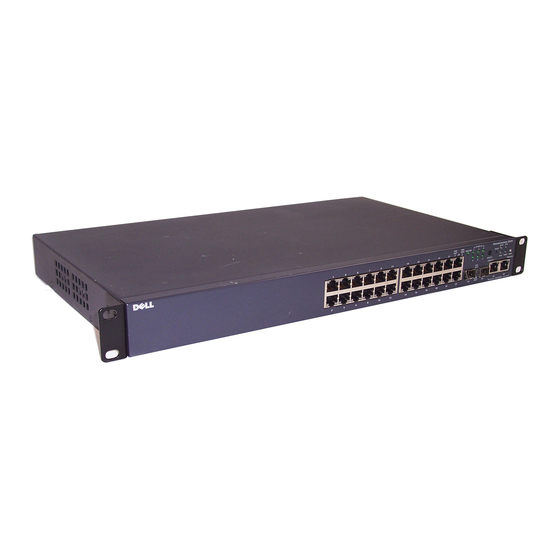
PowerConnect 3448P PowerConnect 3424 The PowerConnect 3424 provides 24 10/100Mbps ports plus two SFP ports, and two Copper ports which can be used to forward traffic in a stand-alone device, or as stacking ports when the device is stacked. The device also provides one RS-232 console port. The PowerConnect 3424 is a stackable device, but also operates as a stand-alone device. -
Page 22: Powerconnect 3448
• Command Line Interface (CLI) PowerConnect 3424/P and PowerConnect 3448/P devices support stacking up to six units per stack, or can operate as stand-alone units. During the Stacking setup, one switch is selected as the Stack Master and another stacking member can be selected as the Backup Master. -
Page 23: Understanding The Stack Topology
Most difficulties incurred in Ring topologies occur when a device in the ring becomes non- functional, or a link is severed. With the PowerConnect 3424/P and PowerConnect 3448/P stack, the system automatically switches to a Stacking Failover topology without any system downtime. -
Page 24: Removing And Replacing Stacking Members
Once the user selects a different Unit ID, it is not erased, and remains valid, even if the unit is reset. Unit ID 1 and Unit ID 2 are reserved for Master enabled units. Unit IDs 3 to 6 can be defined for stack members. -
Page 25: Exchanging Stacking Members
For example, • If a PowerConnect 3424/P replaces PowerConnect 3424/P, all port configurations remain the same. • If a PowerConnect 3448/P replaces the PowerConnect 3448/P, all port configurations remain the same. -
Page 26: Figure 1-4. Powerconnect 3448/P Replaces Powerconnect 3448/P
Configuration Configuration • If a PowerConnect 3448/P replaces PowerConnect 3424/P, the first 3448/P 24 FE ports receive the 3424/P 24 FE port configuration. The GE port configurations remain the same. The remaining ports receive the default port configuration. Figure 1-5. PowerConect 3424/P port replaces PowerConnect 3448/P port... -
Page 27: Switching From The Stack Master To The Backup Stack Master
Figure 1-6. PowerConnect 3448/P port replaces PowerConect 3424/P Port Same Same Configuration Configuration Switching from the Stack Master to the Backup Stack Master The Backup Master replaces the Stack Master if the following events occur: • The Stack Master fails or is removed from the stack. •... -
Page 28: Features Overview
Features Overview This section describes the device features. For a complete list of all updated device features, see the latest software version Release Notes. Power over Ethernet Power over Ethernet (PoE) provides power to devices over existing LAN cabling, without updating or modifying the network infrastructure. -
Page 29: Mdi/Mdix Support
MDI/MDIX Support The device automatically detects whether the cable connected to an RJ-45 port is crossed or straight through, when auto-negotiation is enabled. Standard wiring for end stations is Media-Dependent Interface (MDI) and the standard wiring for hubs and switches is known as Media-Dependent Interface with Crossover (MDIX). For information on configuring MDI/MDIX for ports or LAGs, see "Defining Port Configuration"... -
Page 30: Layer 2 Features
VLAN-aware MAC-based Switching The device always performs VLAN-aware bridging. Classic bridging(IEEE802.1D) is not performed, where frames are forwarded based only on their destination MAC address. However, a similar functionality can be configured for untagged frames. Frames addressed to a destination MAC address that is not associated with any port are flooded to all ports of the relevant VLAN. -
Page 31: Vlan Supported Features
VLAN Supported Features VLAN Support VLANs are collections of switching ports that comprise a single broadcast domain. Packets are classified as belonging to a VLAN based on either the VLAN tag or based on a combination of the ingress port and packet contents. Packets sharing common attributes can be grouped in the same VLAN. -
Page 32: Link Aggregation
Fast Link STP can take up to 30-60 seconds to converge. During this time, STP detects possible loops, allowing time for status changes to propagate and for relevant devices to respond. 30-60 seconds is considered too long of a response time for many applications. The Fast Link option bypasses this delay, and can be used in network topologies where forwarding loops do not occur. -
Page 33: Quality Of Service Features
BootP and DHCP Clients DHCP enables additional setup parameters to be received from a network server upon system startup. DHCP service is an on-going process. DHCP is an extension to BootP. For more information on DHCP, see "Defining DHCP IP Interface Parameters." Quality of Service Features Class Of Service 802.1p Support The IEEE 802.1p signaling technique is an OSI Layer 2 standard for marking and prioritizing... - Page 34 TFTP Trivial File Transfer Protocol The device supports boot image, software, and configuration upload/download via TFTP. Remote Monitoring Remote Monitoring (RMON) is an extension to SNMP, which provides comprehensive network traffic monitoring capabilities (as opposed to SNMP which allows network device management and monitoring).
-
Page 35: Security Features
Security Features Secure Socket Layer (SSL) is an application-level protocol that enables secure transactions of data through privacy, authentication, and data integrity. It relies upon certificates and public and private keys. Port Based Authentication (802.1x) Port based authentication enables authenticating system users on a per-port basis via an external server. -
Page 36: Additional Cli Documentation
Password Management Password management provides increased network security and improved password control. Passwords for SSH, Telnet, HTTP, HTTPS, and SNMP access are assigned security features. For more information on Password Management, see "Managing Passwords". Additional CLI Documentation The CLI Reference Guide, which is available on the Documentation CD, provides information about the CLI commands used to configure the device. -
Page 37: Hardware Description
Hardware Description Port Description PowerConnect 3424 Port Description The PowerConnect 3424 device is configured with the following ports: • 24 Fast Ethernet ports — RJ-45 ports designated as 10/100Base-T ports • 2 Fiber ports — Designated as 1000Base-X SFP ports •... -
Page 38: Powerconnect 3448 Port Description
On the front panel are all the device LEDs. The following figure illustrates the PowerConnect 3424 back: Figure 2-2. PowerConnect 3424 Back Panel The back panel contains an RPS connector, console port, and power connector. -
Page 39: Sfp Ports
There are two buttons on the front panel. The Stack ID button is used to select the unit number. The second button is the Reset Button which is used to manually reset the device. The Reset button does not extend beyond the unit’s front panel surface, so reset by pressing it accidentally is prevented. -
Page 40: Physical Dimensions
The following figure illustrates the 10/100 Base-T port LEDs on The PowerConnect 3424 /P and PowerConnect 3448/P switches: Figure 2-6. RJ-45 Copper Based 10/100 BaseT LEDs Speed/LNK/ACT Speed/LNK/ACT The RJ-45 100 Base-T port on the PowerConnect 3424 /P and PowerConnect 3448/P has two LEDs marked as LNK/ACT. Hardware Description... -
Page 41: Figure 2-7. Rj-45 1000 Baset Led
The following figure illustrates the 100 Base-T LEDs. Figure 2-7. RJ-45 1000 BaseT LED The RJ-45 LED indications for PowerConnect 3424 and PowerConnect 3448 are described in the following table: Table 2-1. PowerConnect 3424 and PowerConnect 3448 RJ-45 100BaseT LED Indications... - Page 42 The RJ-45 LED indications for PowerConnect 3424P and PowerConnect 3448P are described in the following table: Table 2-2. PowerConnect 3424P and PowerConnect 3448P RJ-45 Copper based 100BaseT LED Indications Color Description Speed/Link/Act Green Static The port is currently linked at 100 Mbps. Green Flashing The ports is currently operating at 100 Mbps.
-
Page 43: Gigabit Port Leds
The port is currently operating in Half Duplex mode. SFP LEDs The SFP ports each have one LED marked as LNK/ACT. On the PowerConnect 3424/P and PowerConnect 3448/P devices, the LEDs are located between ports and are round in shape. -
Page 44: System Leds
System LEDs The system LEDs of The PowerConnect 3424 /P and PowerConnect 3448/P devices provide information about the power supplies, fans, thermal conditions, and diagnostics. The following figure illustrates the system LEDS. Figure 2-9. System LEDs The following table describes the system LED indications. -
Page 45: Power Supplies
3424/P and PowerConnect 3448/P devices to a PowerConnect EPS-470 unit, or to connect PowerConnect 3424 and PowerConnect 3448 devices to a PowerConnect RPS-600 unit. The PowerConnect 3424/P and PowerConnect 3448/P devices have an internal power supply (12 Volt). Operation with both power supply units is regulated through load sharing. Power supply LEDs indicate the status of the power supply. -
Page 46: Figure 2-11. Power Connection
DC Power Supply Unit The PowerConnect 3424 and PowerConnect 3448 switches connect to an external RPS-600 unit to provide a redundant power option. No configuration is required. The front panel "RPS" LED indicates whether the external RPS-600 is connected. See Table 2-5 for RPS LED definition. -
Page 47: Stack Id Button
Stack ID button several times until no stacking LED is lit. Reset Button The PowerConnect 3424/P and PowerConnect 3448/P switches have a reset button, located on the front panel, for manual reset of the device. If the Master device is reset, the entire stack is reset. - Page 48 Hardware Description...
-
Page 49: Installing The Powerconnect 3424/P And Powerconnect 3448/P
PowerConnect 3448/P Site Preparation The PowerConnect 3424 /P and PowerConnect 3448/P devices can be mounted in a standard 48.26-am (19-inch) equipment rack, placed on a tabletop or mounted on a wall. Before installing the unit, verify that the chosen location for installation meets the following site requirements: •... -
Page 50: Unpacking The Device
Inspect the device and accessories for damage. Report any damage immediately. Mounting the Device The following mounting instructions apply to The PowerConnect 3424/P and PowerConnect 3448/P devices. The Console port is on the back panel. The power connectors are positioned on the back panel. -
Page 51: Installing On A Flat Surface
Attach the self-adhesive rubber pads on each marked location on the bottom of the chassis. Set the device on a flat surface, leaving 5.08 cm (2 inch) on each side and 12.7 cm (5 inch) at the back. Ensure that the device has proper ventilation. Installing the PowerConnect 3424/P and PowerConnect 3448/P... -
Page 52: Installing The Device On A Wall
Drill holes and place all plugs (not provided) in the holes, in the marked location. Secure the unit to the wall with screws (not provided). Ensure that the ventilation holes are not obstructed. Installing the PowerConnect 3424/P and PowerConnect 3448/P... -
Page 53: Connecting To A Terminal
Connect an RS-232 crossover cable to the ASCII terminal or the serial connector of a desktop system running terminal emulation software. Connect the female DB-9 connector at the other end of the cable to the device serial port connector. Installing the PowerConnect 3424/P and PowerConnect 3448/P... -
Page 54: Connecting A Device To A Power Supply
Members. Stacking PowerConnect 3400 Series Switches Each PowerConnect 3400 series stack contains a single Master unit, and may have a Master Backup unit, while the remaining units are considered stacking Members. Installing the PowerConnect 3424/P and PowerConnect 3448/P... -
Page 55: Figure 3-5. Stacking Cable Diagram
In stacking mode ports designated as G3 and G4 are not displayed in the EWS. The effect is of not being present on the device. This is because the ports receive a different index for stacking. Stack unit identification is performed on the device front panel using the Stack ID button. Installing the PowerConnect 3424/P and PowerConnect 3448/P... -
Page 56: Unit Id Selection Process
When powering up, the configured LED number (corresponding to the previously saved unit ID) begins to flash. The LED flashes for 15 seconds. During this period, select a specific Stack ID by pressing the Stack ID button until the appropriate Stack ID LED is illuminated. Installing the PowerConnect 3424/P and PowerConnect 3448/P... -
Page 57: Starting And Configuring The Device
To connect a terminal to the device Console port: Connect the supplied RS-232 crossover cable to the terminal running VT100 terminal emulation software. Select the appropriate serial port (serial port 1 or serial port 2) to connect to the console. Installing the PowerConnect 3424/P and PowerConnect 3448/P... -
Page 58: Figure 3-7. Connecting To Powerconnect 3400 Series Console Port
To VT100 Terminal NOTE: A console can be connected to the Console port on any unit in the stack, but stack management is performed only from the stack master (unit ID 1 or 2). Installing the PowerConnect 3424/P and PowerConnect 3448/P... -
Page 59: Configuring Powerconnect 3424/P And 3448/P
Configuring PowerConnect 3424/P and 3448/P Configuration Procedures After all the device external connections are completed, a terminal is connected to the device to monitor the boot and other procedures. The order of installation and configuration procedures is illustrated in the following figure: NOTE: Before proceeding, read the release notes for this product. -
Page 60: Booting The Switch
If POST passes successfully, a valid executable image is loaded into RAM. POST messages are displayed on the terminal and indicate test success or failure. The boot process runs approximately 30 seconds. Configuring PowerConnect 3424/P and 3448/P... -
Page 61: Initial Configuration
• Default Gateway IP address The following is displayed: Welcome to Dell Easy Setup Wizard The Setup Wizard guides you through the initial switch configuration, and gets you up and running as quickly as possible. You can skip the setup wizard, and enter CLI mode to manually configure the switch. - Page 62 The wizard automatically assigns the highest access level [Privilege Level 15] to this account. You can use Dell Network Manager or CLI to change this setting, and to add additional management systems. For more information on adding management systems, see the user documentation.
- Page 63 The IP address is defined on the default VLAN (VLAN #1), of which all ports are members. This is the IP address you use to access the CLI, Web interface, or SNMP interface for the switch.To setup an IP address: Configuring PowerConnect 3424/P and 3448/P...
- Page 64 Enter [Y] to complete the Setup Wizard. The following is displayed: Configuring SNMP management interface Configuring user account..Configuring IP and subnet..Thank you for using Dell Easy Setup Wizard. You will now enter CLI mode. Configuring PowerConnect 3424/P and 3448/P...
-
Page 65: Advanced Configuration
1/e1 console(config-if)# ip address dhcp hostname powerconnect console(config-if)# exit console(config)# • Assigning Dynamic IP Addresses (on a VLAN): console# configure console(config)# interface ethernet vlan 1 console(config-if)# ip address dhcp hostname device console(config-if)# exit console(config)# Configuring PowerConnect 3424/P and 3448/P... -
Page 66: Receiving An Ip Address From A Bootp Server
At the system prompt, enter the delete startup configuration command to delete the Startup Configuration from flash. The device reboots with no configuration and in 60 seconds starts sending BOOTP requests. The device receives the IP address automatically. Configuring PowerConnect 3424/P and 3448/P... -
Page 67: Security Management And Password Configuration
Configuring Security Passwords The security passwords can be configured for the following services: • Terminal • Telnet • • HTTP • HTTPS NOTE: Passwords are user-defined. Configuring PowerConnect 3424/P and 3448/P... - Page 68 • When initially logging onto a device through a Telnet session, enter at the password prompt. • When changing a device mode to enable, enter Configuring PowerConnect 3424/P and 3448/P...
- Page 69 When initially enabling an http or https session, enter for user name and admin user1 for password. NOTE: Http and Https services require level 15 access and connect directly to the configuration level access. Configuring PowerConnect 3424/P and 3448/P...
-
Page 70: Startup Procedures
35 seconds (default), the device times out. This default value can be changed through CLI. NOTE: Technical support personnel only can operate the Diagnostics Mode (option . For this [4]) reason, Enter Diagnostics Mode is not described in this guide. Configuring PowerConnect 3424/P and 3448/P... - Page 71 Flash size is: 16M Loading running configuration. Number of configuration items loaded: 5 Loading startup configuration. Number of configuration items loaded: 5 Device configuration: Slot 1 - PowerConnect 3424 HW Rev. ------------------------------- -- Unit Number 1 Standalone -- ------------------------------- BOXP_high_appl_init: dpssIpcInitStandAlone Tapi Version: v1.3.1.6P_01_03...
- Page 72 Repeat the device initial configuration. Password Recovery - option[3] If a password is lost, the Password Recovery procedure can be called from the Startup menu. The procedure enables entry to the device once without password. Configuring PowerConnect 3424/P and 3448/P...
-
Page 73: Software Download Through Tftp Server
Enter the show version command to verify which software version is currently running on the device. The following is an example of the information that appears: console# show version SW version 1.0.0.30 (date 27-Jan-2005 time 13:42:41) Boot version 1.0.0.05 (date 27-Jan-2005 time 15:12:20) HW version Configuring PowerConnect 3424/P and 3448/P... - Page 74 Images currently available on the Flash Image-1 active Image-2 not active (selected for next boot) If the image for the next boot is not selected by entering the boot system command, the system boots from the currently active image. Configuring PowerConnect 3424/P and 3448/P...
- Page 75 Enter the reload command. The following message is displayed: console# reload This command will reset the whole system and disconnect your current session. Do you want to continue (y/n) [n]? Enter y . The device reboots. Configuring PowerConnect 3424/P and 3448/P...
-
Page 76: Port Default Settings
The device supports back pressure for ports configured with the half duplex mode. By default, this feature is disabled. It can be enabled per port. The back-pressure mechanism prevents the sender from transmitting additional traffic temporarily. The receiver may occupy a link so it becomes unavailable for additional traffic. Configuring PowerConnect 3424/P and 3448/P... -
Page 77: Switching Port Default Settings
10/100BaseT copper: auto-negotiation 100 Mbps full duplex 10/100/1000BaseT copper / SFP: auto-negotiation1000 Mbps full duplex Port forwarding state Enabled Port tagging No tagging Flow Control Off (disabled on ingress) Back Pressure Off (disabled on ingress) Configuring PowerConnect 3424/P and 3448/P... - Page 78 Configuring PowerConnect 3424/P and 3448/P...
-
Page 79: Using Dell Openmanage Switch Administrator
Using Dell OpenManage Switch Administrator This section provides an introduction to the Dell OpenManage Switch Administrator user interface. Starting the Application NOTE: Before starting the application the IP address must be defined. For more information, see Initial Configuration. Open a web browser. -
Page 80: Table 5-8. Interface Components
The components list contains a list of the feature components. Components can also be viewed by expanding a feature in the tree view. The information buttons provide access to information about the device and access to Dell Support. For more information, see "Information Buttons." Using Dell OpenManage Switch Administrator... -
Page 81: Device Representation
The Port LEDs are not reflected in PowerConnect front panel in the OpenManage Switch Administrator. LED status can only be determined by viewing the actual device. However, the Stacking LEDs reflect the Stacking port status. For more information about LEDs, see LED Definitions. Using Dell OpenManage Switch Administrator... -
Page 82: Using The Switch Administrator Buttons
The online help pages are context-sensitive. For example, if the IP Addressing page is open, the help topic for that page displays when Help is clicked. About Contains the version and build number and Dell copyright information. Log Out Opens the Log Out window. -
Page 83: Field Definitions
When finished, enter the exit Privileged EXEC mode command. The session quits. NOTE: If a different user logs into the system in the Privileged EXEC command mode, the current user is logged off and the new user is logged in. Using Dell OpenManage Switch Administrator... -
Page 84: Telnet Connection
The Global Configuration mode manages the device configuration on a global level. The Interface Configuration mode configures the device at the physical interface level. Interface commands which require subcommands have another level called the Subinterface Configuration mode. A password is not required. Using Dell OpenManage Switch Administrator... -
Page 85: User Exec Mode
Enter Password: ****** console# console# disable console> Use the exit command to move back to a previous mode. For example, from Interface Configuration mode to Global Configuration mode, and from Global Configuration mode to Privileged EXEC mode. Using Dell OpenManage Switch Administrator... -
Page 86: Global Configuration Mode
The following example illustrates how to access Global Configuration mode and return back to the Privileged EXEC mode: console# console# configure console(config)# exit console# For a complete list of the CLI modes, see the Dell™ PowerConnect™3424/P and PowerConnect 3448/P CLI Guide. Using Dell OpenManage Switch Administrator... -
Page 87: Configuring System Information
Configuring System Information This section provides information for defining system parameters including security features, downloading switch software, and resetting the switch. To open the System page, click System in the tree view. Figure 6-1. System Configuring System Information... -
Page 88: Defining General Switch Information
Defining General Switch Information The General page contains links to pages that allow network managers to configure switch parameters. Viewing Switch Asset Information The Asset page contains parameters for configuring and viewing general device information, including the system name, location, and contact, the system MAC Address, System Object ID, →... -
Page 89: Table 6-12. Asset Cli Commands
Unit No. — Indicates the unit number for which the device asset information is displayed. Service Tag — The service reference number used when servicing the device. Asset Tag (0-16 Characters) — Indicates the user-defined device reference. Serial No. — The device serial number. Defining System Information Open the Asset page. - Page 90 The following is an example of defining the device host name, system contact and device location as well as setting the time and date of the system clock using the CLI commands: console(config)# hostname dell dell (config)# snmp-server contact Dell_Tech_Supp dell (config)# snmp-server location New_York dell (config)# exit Console(config)# snmp-server host 10.1.1.1 management 2...
- Page 91 893658972 mkt-1 89788978 893658973 mkt-2 89788979 893658974 mkt-3 89788980 893658975 mkt-4 89788981 893658976 mkt-5 89788982 893658977 mkt-6 89788983 console# show system Unit Type ---- ----------------- PowerConnect 3424 PowerConnect 3424 PowerConnect 3428 PowerConnect 3424P PowerConnect 3424P PowerConnect 3424P Configuring System Information...
- Page 92 Unit Main Power Supply Redundant Power Supply ---- ----------------- ---------------------- Unit Fan1 Fan2 Fan3 Fan4 Fan5 ---- ---- ---- ---- ---- ---- Unit Temperature (Celsius) Temperature Sensor Status ---- -------------------- ------------------------- Configuring System Information...
-
Page 93: Defining System Time Settings
Defining System Time Settings The Time Synchronization page contains fields for defining system time parameters for both the local hardware clock, and the external SNTP clock. If the system time is kept using an external SNTP clock, and the external SNTP clock fails, and the system time reverts to the local hardware clock. - Page 94 • Ireland — Last weekend of March until the last weekend of October. • Israel — Varies year-to-year. • Italy — Last weekend of March until the last weekend of October. • Japan — Japan does not operate Daylight Saving Time. •...
-
Page 95: Figure 6-3. Time Synchronization
For more information on SNTP, see Configuring SNTP Settings. → → To open the Time Synchronization page, click System General Time Synchronization in the tree view. Figure 6-3. Time Synchronization The Time Synchronization page contains the following fields: Clock Source Clock Source —... - Page 96 Daylight Savings — Enables the Daylight Savings Time (DST) on the device based on the device’s location. The possible field values are: USA — The device switches to DST at 2 a.m. on the first Sunday of April, and reverts to standard time at 2 a.m.
- Page 97 Month — The month of the year in which DST begins every year. The possible field range is Jan-Dec. Time — The time at which DST begins every year. The field format is Hour: Minute, for example, 02:10. To — Defines the recurring time that DST ends each year. For example, DST ends locally every fourth Friday in October at 5:00 am.
-
Page 98: Viewing System Health Information
For example: console(config)# clock summer-time recurring usa console(config)# clock time zone 2 zone TMZ2 console(config)# clock set 10:00:00 apr 15 2004 Table 6-13. Clock Setting CLI Commands Description clock source sntp Configures an external time source for the system clock. clock time zone hours-offset Sets the time zone for display purposes. -
Page 99: Figure 6-4. System Health
Figure 6-4. System Health The System Health page contains the following fields: Unit No. — Indicates the unit number for which the device asset information is displayed. Power Supply Status — The device has two power supplies. Power supply 1 is displayed as PS1 in the interface, while the redundant power supply is displayed as RPS. -
Page 100: Table 6-14. Celsius To Fahrenheit Conversion Table
The following is an example of the system health CLI command. Console> show system System Description: Ethernet switch System Up Time (days,hour:min:sec): 1,22:38:21 System Contact: System Name: RS1 System location: System MAC Address: 00.10.B5.F4.00.01 Sys Object ID: 1.3.6.1.4.1.674.10895.3004 Type: PowerConnect 3424 Temperature Sensors: Configuring System Information... -
Page 101: Managing Power Over Ethernet
Unit Sensor Temperature (Celsius) Status ---- ------ --------------------- ------ Unit Power Supply Source Status ---- ------------ ------ ------ Main Secondary Unit Status ---- ------ Managing Power over Ethernet Power over Ethernet (PoE) provides power to devices over existing LAN cabling, without updating or modifying the network infrastructure. -
Page 102: Figure 6-5. Power Over Ethernet
Figure 6-5. Power Over Ethernet The Power Over Ethernet page contains the following sections: • Global • Port Settings Global The Power over Ethernet Global Settings section contains the following fields: Power Status — Indicates the inline power source status. On —... - Page 103 Port Settings Select a Port — Indicates the specific interface for which PoE parameters are defined and assigned to the powered interface connected to the selected port. PoE Admin Status — Indicates the device PoE mode. The possible field values are: Auto —...
- Page 104 3.84 – 6.49 — Indicates that the port is assigned a power consumption level of 3.84 to 6.49 Watts. 6.49 – 12.95 — Indicates that the port is assigned a power consumption level of 6.49 to 12.95 Watts. Power Device (0-24 characters) — Provides a user-defined powered device description. The field can contain up to 24 characters.
- Page 105 Table 6-16. System Health CLI Commands (continued) CLI Command Description Configures the threshold for triggering alarms power inline usage-threshold Enables PoE device traps power inline traps enable Displays PoE configuration information show power inline [ ethernet interface ] The following is an example of the PoE CLI commands. Console# show power inline Power: On Nominal Power: 150 Watts...
-
Page 106: Viewing Version Information
Viewing Version Information The Versions page contains information about the hardware and software versions currently running. To open the Versions page, click System→ General→ Versions in the tree view. Figure 6-6. Versions The Versions page contains the following fields: Unit No. — Indicates the unit number for which the device versions are displayed. Software Version —... -
Page 107: Managing Stack Members
The following is an example of the CLI commands: console> show version SW version 1.0.0.0 (date 23-Jan-2005 time 17:34:19) Boot version 1.0.0.0 (date 11-Jan-2005 time 11:48:21) HW version 1.0.0 Managing Stack Members The Stack Management page allows network managers to either reset the entire stack or a specific →... - Page 108 Switching Between Stack Masters Open the Stack Management page. Check the Switch Stack Control from Unit 1 to Unit 2 check box. Click Apply Changes. A confirmation message displays. Click OK. The device is reset. After the device is reset, a prompt for a user name and password displays. Configuring Stack Display Order Open the Stack Management page.
-
Page 109: Resetting The Device
Resetting the Device The Reset page enables the device to be reset from a remote location. To open the Reset page, click → → System General Reset in the tree view. The Reset page contains the following field: Reset Unit No. — Resets the selected stacking member. NOTE: Save all changes to the Startup Configuration file before resetting the device. -
Page 110: Configuring Sntp Settings
Configuring SNTP Settings The switch supports the Simple Network Time Protocol (SNTP). SNTP assures accurate network switch clock time synchronization up to the millisecond. Time synchronization is performed by a network SNTP server. SNTP operates only as a client, and cannot provide time services to other systems. - Page 111 Using Anycast polling to get time information for synchronizing device time is preferred to using Broadcast polling to get time information. However, this method is less secure than unicast polling, because SNTP packets are accepted from SNTP servers that are not configured on the device. Broadcast information is used when the server IP address is unknown.
-
Page 112: Defining Sntp Global Parameters
Defining SNTP Global Parameters The SNTP Global Settings page provides information for defining SNTP parameters globally. To open the SNTP Global Settings page, click System → SNTP→ Global Settings in the tree view. Figure 6-8. SNTP Global Settings The SNTP Global Settings page contains the following fields: Poll Interval (60-86400) —... - Page 113 Selecting a Clock Source Open the Time Synchronization page. Define the Clock Source field. Click Apply Changes. The Clock source is selected, and the device is updated. Defining Local Clock Settings Open the Time Synchronization page. Define the fields. Click Apply Changes. The local clock settings are applied.
-
Page 114: Defining Sntp Authentication Methods
Defining SNTP Authentication Methods The SNTP Authentication page enables SNTP authentication between the device and an SNTP server. The means by which the SNTP server is authenticated is also selected in the SNTP Authentication page. Click System → SNTP→ Authentication in the tree view to open the SNTP Authentication page. -
Page 115: Figure 6-10. Add Authentication Key
Figure 6-10. Add Authentication Key Define the fields. Click Apply Changes. The SNMP authentication key is added, and the device is updated. Displaying the Authentication Key Table Open the SNTP Authentication page. Click Show All. The Authentication Key Table opens: Figure 6-11. -
Page 116: Defining Sntp Servers
Defining SNTP Authentication Settings Using CLI Commands The following table summarizes the equivalent CLI commands for setting fields displayed in the SNTP Authentication page. Table 6-21. SNTP Authentication CLI Commands CLI Command Description sntp authenticate Defines authentication for received Simple Network Time Protocol (SNTP) traffic from servers. -
Page 117: Figure 6-12. Sntp Servers
Figure 6-12. SNTP Servers The SNTP Servers page contains the following fields: SNTP Server — Select a user-defined SNTP server IP address. Up to eight SNTP servers can be defined. Poll Interval — Enables polling the selected SNTP Server for system time information, when enabled. -
Page 118: Figure 6-13. Add Sntp Server
Offset — Timestamp difference between the device local clock and the acquired time from the SNTP server. Delay — The amount of time it takes to reach the SNTP server. Remove — Removes a specific SNTP server from the SNTP Servers list, when selected. Adding an SNTP Server Open the SNTP Servers page. - Page 119 Modifying an SNTP Server Open the SNTP Servers page. Click Show All. The SNTP Servers Table opens. Select an SNTP Server entry. Modify the relevant fields. Click Apply Changes. The SNTP Server information is updated. Deleting the SNTP Server Open the SNTP Servers page. Click Show All.
-
Page 120: Defining Sntp Interfaces
Defining SNTP Interfaces The SNTP Interface Settings page contains SNTP interface information. To open the SNTP Interface Settings page, click System→ SNTP→ Interface Settings. Figure 6-15. SNTP Interface Settings The SNTP Interface Settings page contains the following fields: Unit No. — Indicates the stacking member on which the SNTP interface is enabled. Interface —... -
Page 121: Figure 6-16. Add Sntp Interface
Figure 6-16. Add SNTP Interface Define the relevant fields. Click Apply Changes. The SNTP interface is added, and the device is updated. Defining SNTP Interface Settings Using CLI Commands The following table summarizes the equivalent CLI commands for setting fields displayed in the SNTP Interface Settings page. -
Page 122: Managing Logs
Server Polling Encryption Key ----------- -------- --------------- 176.1.1.8 Enabled 176.1.8.179 Disabled Disabled Broadcast Clients: Enabled Broadcast Clients Poll: Enabled Broadcast Interfaces:1/e1, 1/e3 Managing Logs → The Logs page contains links to various log pages. To open the Logs page, click System Logs in the tree view. -
Page 123: Figure 6-17. Global Log Parameters
Provides device information. Debug Provides detailed information about the log. If a Debug error occurs, contact Dell Online Technical Support. The Global Log Parameters page contains fields for defining which events are recorded to which logs. It contains fields for enabling logs globally, and fields for defining log parameters. The Severity log messages are listed from the highest severity to the lowest. - Page 124 The Global Log Parameters page contains the following parameters: Logging — Enables device global logs for Cache, File, and Server Logs. Console logs are enabled by default. Log Authentication Events — Enables generating logs when users are authenticated. Log Copy Files Events — Enables generating logs when files are copied. Log Rename and Delete Files Events —...
- Page 125 Enabling Logs: Open the Global Log Parameters page. Select Enable in the Logging drop-down list. Select the log type and log severity in the Global Log Parameters check boxes. Click Apply Changes. The log settings are saved, and the device is updated. Enabling Logs Using CLI Commands The following table summarizes the equivalent CLI commands for setting fields displayed in the Global Log Parameters page.
-
Page 126: Viewing The Ram Log Table
Viewing the RAM Log Table The RAM Log Table contains information about log entries kept in RAM, including the time the log was entered, the log severity, and a description of the log. To open the RAM Log Table, click →... - Page 127 Viewing and Clearing the RAM Log Table Using the CLI Commands The following table summarizes the equivalent CLI commands for viewing and clearing fields displayed in the RAM Log Table. Table 6-26. RAM Log Table CLI Commands CLI Command Description show logging Displays the state of logging and the syslog messages stored in the internal buffer.
-
Page 128: Viewing The Log File Table
Viewing the Log File Table The Log File Table contains information about log entries saved to the Log File in FLASH, including the time the log was entered, the log severity, and a description of the log message. → → To open the Log File Table, click System Logs File Table in the tree view. - Page 129 Displaying the Log File Table Using the CLI Commands The following table summarizes the equivalent CLI commands for viewing and setting fields displayed in the Log File Table. Table 6-27. Log File Table CLI Commands CLI Command Description show logging file Displays the logging state and the syslog messages stored in the logging file.
-
Page 130: Viewing The Device Login History
Viewing the Device Login History The Login History page contains information for viewing and monitoring device utilization, including the time the user logged in and the protocol used to log on to the device. To open the Login History page, click System→ Logs→ Login History in the tree view. Figure 6-20. - Page 131 Displaying the Device Login History using CLI Commands The following table summarizes the equivalent CLI commands for viewing and setting fields displayed in the Login History page. Table 6-28. Log File Table CLI Commands CLI Command Description show users login-history Displays password management history information.
-
Page 132: Modifying Remote Log Server Definitions
Modifying Remote Log Server Definitions The Remote Log Server Settings page contains fields for viewing and configuring the available Log Servers. In addition, new log servers can be defined, and the log severity sent to each server. To → → open the Remote Log Server Settings page, click System Logs Remote Server Settings in the... -
Page 133: Figure 6-22. Add A Log Server
Sending Logs to a Server: Open the Remote Log Server Settings page. Select a server from the Available Servers drop-down list. Define the fields. Select the log severity in the Severity to Include check boxes. Click Apply Changes. The log settings are saved, and the device is updated. Defining a New Server: Open the Remote Log Server Settings page. -
Page 134: Figure 6-23. Log Servers Table
Figure 6-23. Log Servers Table Removing a Log Server from the Log Servers Table Page: Open the Remote Log Server Settings page. Click Show All. The Log Servers Table page opens. Select a Log Servers Table entry. Select the Remove check box to remove the server(s). Click Apply Changes. -
Page 135: Defining Ip Addressing
The following is an example of the CLI commands: console> enable console# configure console(config) # logging 10.1.1.1 severity critical console(config)# end console# show logging Logging is enabled. Console Logging: Level debug. Console Messages: 5 Dropped. Buffer Logging: Level debug. Buffer Messages: 16 Logged, 16 Displayed, 200 Max. - Page 136 The Default Gateway page contains the following fields: User Defined — The device’s Gateway IP address. Active — Indicates if the Gateway is active. Remove User Defined — Removes the device’s Gateway from the Default Gateway drop-down list, when selected. Selecting a Device’s Gateway: Open the Default Gateway page.
-
Page 137: Defining Ip Interfaces
Defining IP Interfaces The IP Interfaces Parameters page contains fields for assigning IP parameters to interfaces. To → → open the IP Interfaces Parameters page, click System IP Addressing IP Interface Parameters in the tree view. Figure 6-24. IP Interfaces Parameters The IP Interfaces Parameters page contains the following parameters: IP Address —... -
Page 138: Figure 6-25. Add A Static Ip Interface
Figure 6-25. Add a Static IP Interface Network Mask — Indicates the subnetwork mask of the source IP address. Complete the fields on the page. Click Apply Changes. The new IP address is added to the interface, and the device is updated. Modifying IP Address Parameters Open the IP Interfaces Parameters page. - Page 139 Defining IP Interfaces Using CLI Commands The following table summarizes the equivalent CLI commands for setting fields displayed in the IP Interfaces Parameters page. Table 6-31. IP Interface Parameters CLI Commands CLI Command Description ip address ip-address {mask | Sets an IP address. prefix-length} no ip address [ip-address] Removes an IP address...
-
Page 140: Defining Dhcp Ip Interface Parameters
Defining DHCP IP Interface Parameters The DHCP IP Interface page contains parameters for defining DHCP clients connected to the device. To open the DHCP IP Interface page, click System→ IP Addressing→ DHCP IP Interface in the tree view. Figure 6-27. DHCP IP Interface The DHCP IP Interface page contains the following fields: Interface —... - Page 141 Modifying a DHCP IP Interface Open the DHCP IP Interface page. Modify the fields. Click Apply Changes. The entry is modified, and the device is updated. Deleting a DHCP IP Interface Open the DHCP IP Interface page. Click Show All. The DHCP Client Table opens.
-
Page 142: Configuring Domain Name Systems
Configuring Domain Name Systems Domain Name System (DNS) converts user-defined domain names into IP addresses. Each time a domain name is assigned the DNS service translates the name into a numeric IP address. For example, www.ipexample.com is translated into 192.87.56.2. DNS servers maintain domain name databases and their corresponding IP addresses. - Page 143 Figure 6-29. Add DNS Server DNS Server — DNS Server IP address. Define the relevant fields. Click Apply Changes. The new DNS server is defined, and the device is updated. Displaying the DNS Servers Table Open the Domain Naming System (DNS) page. Click Show All.
- Page 144 Configuring DNS Servers Using the CLI Commands The following table summarizes the CLI commands for configuring device system information. Table 6-33. DNS Server CLI Commands CLI Command Description ip name-server server-address Sets the available name servers. Up to eight name servers can be set.
-
Page 145: Defining Default Domains
Defining Default Domains The Default Domain Name page provides information for defining default DNS domain names. To open the Default Domain Name page, click System→ IP Addressing→ Default Domain Name. Figure 6-31. Default Domain Name The Default Domain Name page contains the following fields: Default Domain Name (1-158 characters) —... -
Page 146: Mapping Domain Host
The following is an example of the CLI commands: console(config)# ip domain-name dell.com Mapping Domain Host The Host Name Mapping page provides parameters for assigning IP addresses to static host names. - Page 147 The Host Name Mapping page contains the following fields: Host Name — Contains a Host Name list. Host Names are defined in the Add Host Name Mapping page. Each host provides one IP address. IP Address (X.X.X.X) — Provides an IP address that is assigned to the specified host name. Type —...
- Page 148 Figure 6-34. Hosts Name Mapping Table Removing Host Name from IP Address Mapping Open the Host Name Mapping page. Click Show All. The Host Mapping Table page opens. Select a Host Name Mapping Table entry. Check the Remove checkbox. Click Apply Changes. The Host Mapping Table entry is deleted, and the device is updated.
-
Page 149: Defining Arp Settings
Defining ARP Settings The Address Resolution Protocol (ARP) converts IP addresses into physical addresses, and maps the IP address to a MAC address. ARP allows a host to communicate with other hosts only when the IP address of its neighbors is known. To open the ARP Settings page, click System→ IP Addressing→... - Page 150 IP Address — The station IP address, which is associated with the MAC address filled in below. MAC Address — The station MAC address, which is associated in the ARP table with the IP address. Status — The ARP Table entry status. Possible field values are: Dynamic —...
- Page 151 Configuring ARP Using the CLI Commands The following table summarizes the equivalent CLI commands for setting fields displayed in the ARP Settings page. Table 6-36. ARP Settings CLI Commands CLI Command Description arp ip_addr hw_addr Adds a permanent entry in the ARP cache. {ethernet interface-number | vlan vlan-id | port-channel number}...
-
Page 152: Running Cable Diagnostics
Running Cable Diagnostics The Diagnostics page contains links to pages for performing virtual cable tests on copper cables. To open the Diagnostics page, click System→ Diagnostics in the tree view. Viewing Copper Cable Diagnostics The Copper Cables page contains fields for performing tests on copper cables. Cable testing provides information about where errors occurred in the cable, the last time a cable test was performed, and the type of cable error which occurred. - Page 153 Cable Fault Distance — The distance from the port where the cable error occurred. Last Update — The last time the port was tested. Approximate Cable Length — The approximate cable length. This test can only be performed when the port is up and operating at 1 Gbps. Performing a Cable Test Ensure that both ends of the copper cable are connected to a device.
-
Page 154: Viewing Optical Transceiver Diagnostics
The following is an example of the CLI commands: console> enable Console# test copper-port tdr 1/e3 Cable is open at 100 meters. Console# show copper-port cable-length Port Length (meters) ---- --------------- 1/e3 110-140 1/e4 Fiber NOTE: The cable length returned by the Integrated Cable Tester (ICT) is an approximation in the ranges of up to 50 meters, 50m-80m, 80m-110m, 110m-120m, or more than 120m. - Page 155 The Optical Transceiver page contains the following fields: Port — The port IP address on which the cable is tested. Temperature — The temperature (C) at which the cable is operating. Voltage — The voltage at which the cable is operating. Current —...
-
Page 156: Managing Switch Security
The following is an example of the CLI command: Console# show fiber-ports optical-transceiver detailed Port Temp Voltage Current Output Input POWER [Volt] [mA] [mWatt] Fault [mWatt] ---- ---- ------ ----- ------ ------ ------ ----- 1/e1 5.15 1.789 1.789 1/e2 5.15 1.789 1.789 Managing Switch Security... - Page 157 Figure 6-38. Access Profiles The Access Profiles page contains following fields: Access Profile — User-defined Access Profile lists. The Access Profile list contains a default value of Console Only. When this access profile is selected, active management of the device is performed using the console connection only.
- Page 158 Defining Rules for an Access Profile: Open the Access Profiles page. Click Add Profile. The Add an Access Profile page opens: Figure 6-39. Add an Access Profile The Add an Access Profile page contains the following additional fields: Access Profile Name (1-32 Characters) — User-defined name for the access profile. The Access Profile name can contain up to 32 characters.
- Page 159 Define the Access Profile Name field. Define the relevant fields. Click Apply Changes. The new Access Profile is added, and the device is updated. Adding Rules to Access Profile NOTE: The first rule must be defined to beginning matching traffic to access profiles. Open the Access Profile page.
- Page 160 Figure 6-41. Profile Rules Table Removing a Rule Open the Access Profiles page. Click Show All. The Profile Rules Table page opens. Select a rule. Select the Remove check box. Click Apply Changes. The selected rule is deleted, and the device is updated. Defining Access Profiles Using CLI Commands The following table summarizes the equivalent CLI commands for setting fields displayed in the Access Profiles page.
- Page 161 Table 6-39. Access Profiles CLI Commands CLI Command Description deny [ethernet interface- Sets port denying conditions for the management number | vlan vlan-id | port- access list, and the selected management method. channel number] [service service] deny ip-source ip-address Sets port denying conditions for the management [mask mask | prefix-length] access list, and the selected management method.
- Page 162 The following is an example of the CLI commands: console(config)# management access-list mlist console(config-macl)# permit ethernet 1/e1 console(config-macl)# permit ethernet 1/e2 console(config-macl)# deny ethernet 1/e3 console(config-macl)# deny ethernet 1/e4 console(config-macl)# exit console(config)# management access-class mlist console(config)# exit console# show management access-list mlist ----- permit ethernet 1/e1...
-
Page 163: Defining Authentication Profiles
Defining Authentication Profiles The Authentication Profiles page contains fields for selecting the user authentication method on the device. User authentication occurs: • Locally • Via an external server User authentication can also be set to None. User authentication occurs in the order the methods are selected. For example, if both the Local and RADIUS options are selected, the user is authenticated first locally. - Page 164 Optional Methods — User authentication methods. The possible options are: None — No user authentication occurs. Local — User authentication occurs at the device level. The device checks the user name and password for authentication. RADIUS — User authentication occurs at the RADIUS server. For more information, see Configuring RADIUS Settings.
- Page 165 Figure 6-43. Add Authentication Profile Configure the profile. NOTE: Do not include blank spaces in the name of the new profile. Click Apply Changes. The authentication profile is updated to the device. Displaying the Authentication Profiles Table: Open the Authentication Profiles page. Click Show All.
-
Page 166: Selecting Authentication Profiles
Configuring an Authentication Profile Using CLI Commands The following table summarizes the equivalent CLI commands for setting fields displayed in the Authentication Profiles page. Table 6-40. Authentication Profile CLI Commands CLI Command Description aaa authentication login Configures login authentication. {default | list-name} method1 [method2.] no aaa authentication login Removes a login authentication profile. - Page 167 Figure 6-44. Select Authentication The Select Authentication page contains the following fields: Console — Authentication profiles used to authenticate console users. Login — Specifies authentication profiles to be used for users logging into the console interface. Enable — pecifies authentication profiles to be used for users enabling the Privileged EXEC mode from the console interface.
- Page 168 Applying an Authentication List to Console Sessions Open the Select Authentication page. Select an Authentication Profile in the Console field. Click Apply Changes. Console sessions are assigned an Authentication List. Applying an Authentication Profile to Telnet Sessions Open the Select Authentication page. Select an Authentication Profile in the Telnet field.
- Page 169 Assigning Access Authentication Profiles or Sequences Using CLI Commands The following table summarizes the equivalent CLI commands for setting fields displayed in the Select Authentication page. Table 6-41. Select Authentication CLI Commands CLI Command Description enable authentication Indicates the authentication method list when accessing [default | list-name] a higher privilege level from a remote Telnet, Console or SSH.
-
Page 170: Managing Passwords
Line Login Method List Enable Method List ---- ----------------- ------------------ Console Default Default Telnet Default Default Default Default http : Local https : Local dot1x Managing Passwords Password management provides increased network security and improved password control. Passwords for SSH, Telnet, HTTP, HTTPS, and SNMP access are assigned security features, which include: •... - Page 171 Figure 6-45. Password Management The Password Management page contains the following fields: Password Minimum Length (8-64) — Indicates the minimum password length, when checked. For example, the administrator can define that all passwords must have a minimum of 10 characters. Consecutive Passwords Before Re-use —...
- Page 172 Password Management Using CLI Commands The following table summarizes the equivalent CLI commands for setting fields displayed in the Password Management page. Table 6-42. Password Management Using CLI Commands CLI Command Description password min-length length Defines the minimum password length. password history number Defines the amount of times a password is changed, before the password can be reused.
-
Page 173: Defining The Local User Databases
Line Password Password Lockout Aging Expiry date ------- -------- ----------- ------- Telnet Console console # show users accounts Username Privilege Password Password Lockout Aging Expiry Date -------- --------- -------- ----------- ------- 18-Feb-2005 Defining the Local User Databases The Local User Database page contains fields for defining users, passwords and access levels. To open the Local User Database page, click System→... - Page 174 The Local User Database page contains the following fields: User Name — List of users. Access Level — User access level. The lowest user access level is 1 and 15 is the highest user access level. Users with access level 15 are Privileged Users, and only they can access and use the OpenManage Switch Administrator.
- Page 175 Figure 6-47. Add a User Define the fields. Click Apply Changes. The new user is defined, and the device is updated. Displaying the Local User Table: Open the Local User Database page. Click Show All. The Local User Table opens: Figure 6-48.
- Page 176 Deleting Users: Open the Local User Database page. Click Show All. The Local User Table opens. Select a User Name. Select the Remove check box. Click Apply Changes. The selected user is deleted, and the device is updated. Assigning Users Using CLI Commands The following table summarizes the equivalent CLI commands for setting fields displayed in the Local User Database page.
-
Page 177: Defining Line Passwords
Defining Line Passwords The Line Password page contains fields for defining line passwords for management methods. To open the Line Password page, click System → Management Security→ Line Passwords in the tree view. Figure 6-49. Line Password The Line Password page contains the following fields: Line Password for Console/Telnet/Secure Telnet —... - Page 178 The following table summarizes the equivalent CLI commands for setting fields displayed in the Line Password page. Table 6-44. Line Password CLI Commands CLI Command Description password password Indicates a password on a line. [encrypted] The following is an example of the CLI commands: console(config-line)# password dell Configuring System Information...
-
Page 179: Defining Enable Passwords
Defining Enable Passwords The Enable Password page sets a local password to control access to Normal and Privilege levels. To open the Enable Password page, click System → Management Security → Enable Passwords in the tree view. Figure 6-50. Enable Password The Enable Password page contains the following fields: Select Enable Access Level —... -
Page 180: Defining Tacacs+ Settings
Defining a New Enable Password: Open the Enable Password page. Define the fields. Click Apply Changes. The new Enable password is defined, and the device is updated. Assigning Enable Passwords Using CLI Commands The following table summarizes the equivalent CLI commands for setting fields displayed in the Enable Password page. - Page 181 Figure 6-51. TACACS+ Settings The TACACS+ Settings page contains the following fields: Host IP Address — Indicates the TACACS+ Server IP address. Priority (0-65535) — Indicates the order in which the TACACS+ servers are used. The default is 0. Source IP Address — The device source IP address used for the TACACS+ session between the device and the TACACS+ server.
- Page 182 The TACACS+ default parameters are user-defined defaults. The default settings are applied to newly defined TACACS+ servers. If default values are not defined, the system defaults are applied to the new TACACS+ servers. The following are the TACACS+ defaults: Source IP Address — The default device source IP address used for the TACACS+ session between the device and the TACACS+ server.
- Page 183 Figure 6-53. TACACS+ Table Removing a TACACS+ Server Open the TACACS+ Table page. Click Show All. The TACACS+ Table opens: Select a TACACS+ Table entry. Select the Remove check box. Click Apply Changes. The TACACS+ server is removed, and the device is updated. Defining TACACS+ Settings Using CLI Commands The following table summarizes the equivalent CLI commands for setting fields displayed in theTACACS+ Settings page.
-
Page 184: Configuring Radius Settings
The following is an example of the CLI commands: console# show tacacs Device Configuration IP address Status Port Single TimeOut Source IP Priority Connection ----------- --------- ---- ---------- -------- --------- --------- 12.1.1.2 12.1.1.1 Connected Global values ----------------- TimeOut : 5 Device Configuration -------------------- Source IP : 0.0.0.0... - Page 185 Figure 6-54. RADIUS Settings The RADIUS Settings page contains the following pages: IP Address — The list of Authentication Server IP addresses. Priority (0-65535) — The server priority. The possible values are 0-65535, where 0 is the highest value. This is used to configure the order in which servers are queried. Authentication Port —...
- Page 186 The following fields set the RADIUS default values: NOTE: If host-specific Timeouts, Retries, or Dead time values are not specified, the Global values (Defaults) are applied to each host. Default Retries (1-10) — Indicates the default number of transmitted requests sent to RADIUS server before a failure occurs.
- Page 187 Define the fields. Click Apply Changes. The new RADIUS server is added, and the device is updated. Displaying the RADIUS Server List: Open the RADIUS Settings page. Click Show All. The RADIUS Servers List opens: Figure 6-56. RADIUS Servers List Removing a RADIUS Server Open the RADIUS Settings page.
- Page 188 The following is an example of CLI commands: Console(config)# radius-server timeout 5 Console(config)# radius-server retransmit 5 Console(config)# radius-server deadtime 10 Console(config)# radius-server key dell-server Console(config)# radius-server host 196.210.100.1 auth-port 127 timeout 20 Console# show radius-servers IP address Auth...
-
Page 189: Defining Snmp Parameters
Defining SNMP Parameters Simple Network Management Protocol (SNMP) provides a method for managing network devices. The switch supports the following SNMP versions: • SNMPv1 (version 1) • SNMPv2 (version 2) • SNMPv3 (version 3) SNMP v1 and v2 The SNMP agents maintains a list of variables, which are used to manage the switch. The variables are defined in the Management Information Base (MIB). -
Page 190: Defining Snmp Global Parameters
Defining SNMP Global Parameters The SNMP Global Parameters page permits enabling both SNMP and Authentication notifications. To open the SNMP Global Parameters page, click System → SNMP → Global Parameters in the tree view. Figure 6-57. SNMP Global Parameters The SNMP Global Parameters page contains the following fields: Local Engine ID —... - Page 191 Enabling SNMP Notifications Open the SNMP Global Parameters page. Select Enable in the SNMP Notifications field. Click Apply Changes. SNMP notifications are enabled, and the device is updated. Enabling Authentication Notifications Open the SNMP Global Parameters page. Select Enable in the Authentication Notifications field. Click Apply Changes.
- Page 192 The following is an example of the CLI commands: Console(config)# snmp-server enable traps Console(config)# snmp-server trap authentication Console# show snmp Community-String Community-Access View name IP address ---------------- ----------------- --------- ---------- public read only view-1 Community-String Group name IP address Type ---------------- ---------- ---------- ----...
-
Page 193: Defining Snmp View Settings
Defining SNMP View Settings SNMP Views provide access or block access to device features or feature aspects. For example, a view can be defined which states that SNMP group A has read only (R/O) access to Multicast groups, while SNMP group B has read-write (R/W) access to Multicast groups. Feature access is granted via the MIB name, or MIB Object ID. - Page 194 Adding a View Open the SNMPv3 View Settings page. Click Add. The Add A View page opens: Figure 6-59. Add A View Define the field. Click Apply Changes. The SNMP View is added, and the device is updated. Displaying the View Table Open the SNMPv3 View Settings page.
- Page 195 Defining SNMPv3 Views Using CLI Commands The following table summarizes the equivalent CLI commands for defining fields displayed in the SNMPv3 View Settings page. Table 6-49. SNMP View CLI Commands CLI Command Description Creates or updates a view entry. snmp-server view view-name oid-tree {included | excluded} Displays the configuration of views.
-
Page 196: Defining Snmp Access Control
Defining SNMP Access Control The Access Control page provides information for creating SNMP groups, and assigning SNMP access control privileges to SNMP groups. Groups allow network managers to assign access rights to specific device features, or features aspects. To open the Access Control Group page, click System → SNMP → Access Control in the tree view. Figure 6-61. - Page 197 Operation — Defines the group access rights. The possible field values are: Read — The management access is restricted to read-only, and changes cannot be made to the assigned SNMP view. Write — The management access is read-write and changes can be made to the assigned SNMP view.
- Page 198 Removing SNMP Groups Open the Access Control Group page. Click Show All. The Access Table opens. Select a SNMP group. Check the Remove checkbox. Click Apply Changes. The SNMP group is deleted, and the device is updated. Defining SNMP Access Control Using CLI Commands The following table summarizes the equivalent CLI commands for defining fields displayed in the Access Control Group page.
-
Page 199: Assigning Snmp User Security
Assigning SNMP User Security The SNMPv3 User Security Model (USM) page enables assigning system users to SNMP groups, as well as defining the user authentication method. To open the SNMPv3 User Security Model (USM) page, click System→ SNMP → User Security Model in the tree view. - Page 200 MD5 Password — Indicates that HMAC-MD5-96 password is used for authentication. The user should enter a password. SHA Password — Users are authenticated using the HMAC-SHA-96 authentication level. The user should enter a password. None — No user authentication is used. Password (0-32 Characters) —...
- Page 201 Displaying the User Security Model Table Open the SNMPv3 User Security Model (USM) page. Click Show All. The User Security Model Table opens: Figure 6-66. User Security Model Table Deleting an User Security Model Table Entry Open the SNMPv3 User Security Model (USM) page. Click Show All.
-
Page 202: Defining Snmp Communities
The following is an example of the CLI commands: console (config)# snmp-server user John user-group auth-md5 1234 console (config)# end console# show snmp users Name Group Name Auth Method Remote ------- ---------- ----------- ------ John user-group Defining SNMP Communities Access rights are managed by defining communities on the SNMPv1,2 Community page. When the community names are changed, access rights are also changed. - Page 203 Basic — Enables SNMP Basic mode for a selected community. The possible field values are: Access Mode — Defines the access rights of the community. The possible field values are: Read-Only — Management access is restricted to read-only, and changes cannot be made to the community.
- Page 204 SNMP protocol based on community-group group access rights. community group-name [ ip-address ] Displays the current SNMP device show snmp configuration. The following is an example of the CLI commands: Console (config)# snmp-server community dell ro 10.1.1.1 Configuring System Information...
-
Page 205: Defining Snmp Notification Filters
Defining SNMP Notification Filters The Notification Filter page permits filtering traps based on OIDs. Each OID is linked to a device feature or a feature aspect. The Notification Filter page also allows network managers to filter notifications. To open the Notification Filter page, click System→ SNMP → Notification Filters in the tree view. Figure 6-69. - Page 206 Figure 6-70. Add Filter Define the relevant fields. Click Apply Changes. The new filter is added, and the device is updated. Displaying the Filter Table Open the Notification Filter page. Click Show All. The Filter Table opens: Figure 6-71. Filter Table Removing a Filter Open the Notification Filter page.
- Page 207 Configuring Notification Filters Using CLI Commands The following table summarizes equivalent CLI commands for defining fields displayed in the Notification Filter page. Table 6-53. SNMP Notification Filter CLI Commands CLI Command Description Creates or updates an SNMP notification filter. snmp-server filter filter-name oid-tree {included | excluded} Displays the configuration of SNMP...
-
Page 208: Defining Snmp Notification Recipients
Defining SNMP Notification Recipients The Notification Recipients page contains information for defining filters that determine whether traps are sent to specific users, and the trap type sent. SNMP notification filters provide the following services: • Identifying Management Trap Targets • Trap Filtering •... - Page 209 SNMPv1,2 — SNMP versions 1 and 2 are enabled for the selected recipient. Define the following fields for SNMPv1 and SNMPv2: Community String (1-20 Characters) — Identifies the community string of the trap manager. Notification Version — Determines the trap type. The possible field values are: SNMP V1 —...
- Page 210 Figure 6-73. Add Notification Recipients Define the relevant fields. Click Apply Changes. The notification recipient is added, and the device is updated. Displaying Notification Recipients Tables Open Notification Recipients page. Click Show All. The Notification Recipients Tables page opens: Figure 6-74. Notification Recipients Tables Configuring System Information...
- Page 211 Deleting Notification Recipients Open Notification Recipients page. Click Show All. The Notification Recipients Tables page opens. Select a notification recipient in either the SNMPV1,2 Notification Recipient or SNMPv3 Notification Recipient Tables. Check the Remove checkbox. Click Apply Changes. The recipient is deleted, and the device is updated. Configuring SNMP Notification Recipients Using CLI Commands The following table summarizes the equivalent CLI commands for viewing fields displayed in the Notification Recipients page.
-
Page 212: Managing Files
The following is an example of the CLI commands: console(config)# snmp-server host 172.16.1.1 private console(config)# end console# show snmp Community-String Community-Access View name IP address ---------------- ---------------- --------- ---------- public read only user-view private read write default 172.16.1.1 private DefaultSuper 172.17.1.1 Managing Files Use the File Management page to manage device software, the image file, and the configuration files. -
Page 213: Downloading Files
• Image Files — System file images are saved in two Flash Files called Image 1 and Image 2. The active image stores the active copy, while the other image stores a second copy. The device boots and runs from the active image. If the active image is corrupted, the system automatically boots from the non-active image. - Page 214 Destination File Name — The destination file type to which the file is downloaded. The possible field values are: Software Image — Downloads the Image file. Boot Code — Downloads the Boot file. Configuration Download TFTP Server IP Address — The TFTP Server IP Address from which the configuration files are downloaded.
-
Page 215: Uploading Files
Downloading Files Using CLI Commands The following table summarizes the equivalent CLI commands for setting fields displayed in the File Download from Server page. Table 6-55. File Download CLI Commands CLI Command Description copy source-url destination-url Copies any file from a source to a destination. The following is an example of the CLI commands: console# copy tftp://10.6.6.64/pp.txt startup-config ..! - Page 216 Figure 6-76. File Upload to Server The File Upload to Server page contains the following fields: Firmware Upload — The Firmware file is uploaded. If Firmware Upload is selected, the Configuration Upload fields become unavailable. Configuration Upload — The Configuration file is uploaded. If Configuration Upload is selected, the Active Image Upload fields become unavailable.
- Page 217 NOTE: This list of user-defined configuration files only appears if the user had created backup configuration files. For example, if the user copied the running configuration file to a user-defined configuration file called BACKUP-SITE-1, this list appears on the File Upload to Server page and the BACKUP-SITE-1 configuration file appears in the list.
-
Page 218: Activating Image Files
Activating Image Files The Active Images page allows network managers to select and reset the Image files. The Active Image file for each unit in a stacking configuration can be individually selected. To open the Active Images page, click System → File Management → Active Images in the tree view. Figure 6-77. -
Page 219: Copying Files
Working with the Active Image File Using CLI Commands The following table summarizes the equivalent CLI commands for viewing fields displayed in the Active Images. Table 6-57. File Upload CLI Commands CLI Command Description boot system [unit | unit ] Indicates the system image that the device loads at {image-1 | image-2} startup. - Page 220 Destination — Indicates the destination configuration file to which the source file is copied. Files cannot be copied to the Backup Master’s backup file. Backup files appear in the Destination Unit field only if backup files have been defined. Select the New File Name checkbox and indicate the name of the new file to copy the source file to a new backup configuration file.
-
Page 221: Managing Device Files
The following is an example of the CLI commands: console# delete startup-config Startup file was deleted console# console# copy running-config startup-config 01-Jan-2000 06:55:32 %COPY-W-TRAP: The copy operation was completed successfully Copy succeeded console# Managing Device Files The Files on File System page provides information about files currently stored on the system, including file names, file sizes, files modifications, and file permissions. - Page 222 Permission — Indicates the permission type assigned to the file. The possible field values are: Read Only — Indicates a read-only file. Read Write — Indicates a read-write file. Remove — Deletes the file, when checked. Rename — Permits renaming the file. The file name is renamed in the File Name field. Total Bytes —...
-
Page 223: Configuring General Settings
syslog1.sys 262144 22-Feb-2005 18:49:27 syslog2.sys 262144 22-Feb-2005 18:49:27 directory.prv 262144 06-Feb-2005 17:55:31 startup-config 524288 22-Feb-2005 11:56:03 Total size of flash: 16646144 bytes Free size of flash: 4456448 bytes Configuring General Settings Use Advanced Settings to set miscellaneous global attributes of the switch. The changes to these attributes are applied only after the switch is reset. - Page 224 The General Settings page contains the following information: Attribute — The general setting attribute. Current — The currently configured value. After Reset — The future (after reset) value. By entering a value in the After Reset column, memory is allocated to the field table. Max RAM Log Entries (20-400) —...
-
Page 225: Configuring Switch Information
Configuring Switch Information This section provides all system operation and general information for configuring network security, ports, Address tables, GARP, VLANs, Spanning Tree, Port Aggregation, and Multicast Support. Configuring Network Security Use the Network Security page to set network security through both access control lists and locked ports. - Page 226 • Enables user based authentication. Specific VLANs in the device are always available, even if specific ports attached to the VLAN are unauthorized. • For example, Voice over IP does not require authentication, while data traffic requires authentication. VLANs for which authorization is not required can be defined. Unauthenticated VLANs are available to users, even if the ports attached to the VLAN are defined as authorized.
-
Page 227: Configuring Port Based Authentication
Configuring Port Based Authentication The Port Based Authentication page allows network managers to configure port based authentication. To open the Port Based Authentication page, click Switch → Network Security → Port Based Authentication. Figure 7-1. Port Based Authentication The Port Based Authentication page contains the following fields: Port Based Authentication State —... - Page 228 Guest VLAN — Enables using a guest VLAN for unauthorized ports. If a Guest VLAN is enabled, the unauthorized port automatically joins the VLAN selected in VLAN List field. The field default is disabled. Interface — Contains an interface list for which port based authentication is enabled. User Name —...
- Page 229 Displaying the Port Based Authentication Table Open the Port Based Authentication page. Click Show All. The Port Based Authentication Table opens: Figure 7-2. Port Based Authentication Table In addition to the fields in the Port Based Authentication Table also displays the following fields: Unit No.
- Page 230 Enabling Port Based Authentication Using the CLI Commands The following table summarizes the equivalent CLI commands for enabling the port based authentication as displayed in the Port Based Authentication table. Table 7-61. Port Authentication CLI Commands CLI Command Description aaa authentication dot1x Specifies one or more authentication, default method1 [method2.] authorization, and accounting (AAA) methods for...
-
Page 231: Configuring Advanced Port Based Authentication
The following is an example of the CLI commands: Console# show dot1x Interface Admin Mode Oper Mode Reauth Reauth Username Control Period --------- ---------- ---------- -------- ------ -------- 1/e1 Auto Authorized 3600 1/e2 Auto Authorized 3600 John 1/e3 Auto Unauthorized Ena 3600 Clark 1/e4... - Page 232 The Multiple Hosts page contains the following fields: Port — The port number for which Advanced Port Based Authentication is enabled. Multiple Hosts — Enables or disables a single host to authorize multiple hosts for system access. This setting must be enabled in order to either disable the ingress-filter, or to use port-lock security on the selected port.
- Page 233 Figure 7-4. Multiple Hosts Table Configuring Switch Information...
- Page 234 Enabling Multiple Hosts Using the CLI Commands The following table summarizes the equivalent CLI commands for enabling the advanced port based authentication as displayed in the Multiple Hosts page. Table 7-62. Multiple Hosts CLI Commands CLI Command Description dot1x multiple-hosts Allows multiple hosts (clients) on an 802.1X- authorized port that has the dot1x port-control interface configuration command set to auto.
-
Page 235: Authenticating Users
Authenticating Users The Authenticated Users page displays user port access lists. The User Access Lists are defined in the Add User Name page. To open the Authenticated Users page, click Switch → Network Security → Authenticated Users. Figure 7-5. Authenticated Users The Authenticated Users page contains the following fields: User Name —... - Page 236 Displaying the Authenticated Users Table Open the Authenticated Users page. Click Show All. The Authenticated Users Table opens: Figure 7-6. Authenticated Users Table Authenticating Users Using the CLI Commands The following table summarizes the equivalent CLI commands for authenticating users as displayed in the Authenticated Users page.
-
Page 237: Configuring Port Security
Configuring Port Security Network security can be enhanced by limiting access on a specific port only to users with specific MAC addresses. The MAC addresses can be dynamically learned, up to that point, or they can be statically configured. Locked port security monitors both received and learned packets that are received on specific ports. - Page 238 Figure 7-7. Port Security The Port Security page contains the following fields: Interface — The selected interface type on which Locked Port is enabled. Port — The selected interface type is a port. LAG — The selected interface type is a LAG. Current Port Status —...
- Page 239 Action on Violation — The action to be applied to packets arriving on a locked port. The possible field values are: Forward — Forwards the packets from an unknown source, however, the MAC address is not learned. Discard — Discards the packets from any unlearned source. This is the default value. Shutdown —...
- Page 240 The Port Security Table contains the additional following fields: Unit No. — Specifies the stacking unit for which locked port information is displayed. Copy Parameters from — Copies parameters to the selected unit number. Configuring Locked Port Security with CLI Commands The following table summarizes the equivalent CLI commands for configuring Locked Port security as displayed in the Port Security page.
-
Page 241: Defining Mac Based Acls
Defining MAC Based ACLs Access Control Lists (ACL) allow network managers to define classification actions and rules for specific ingress ports. ACLs contain multiple classification rules and actions. Each classification rule and action are called Access Control Element (ACE). ACEs are the filters that determine traffic classifications. - Page 242 Figure 7-10. Add MAC Based ACLs Define the fields. Click Apply Changes. The MAC-based ACL is defined, and the device is updated. Displaying ACL-Specific ACEs Open the MAC Based ACL page. Select an ACL. Click Show All. The ACEs Associated with MAC ACL page opens. Removing ACLs Open the MAC Based ACL page.
- Page 243 Assigning MAC based ACEs to ACLs Using the CLI Commands The following table summarizes the equivalent CLI commands for assigning MAC based ACEs to ACLs, as displayed in the MAC Based ACL page. Table 7-65. MAC-Based ACE CLI Commands CLI Command Description Creates Layer 2 MAC ACLs, and enters to MAC-Access mac access-list name...
-
Page 244: Configuring Acl Binding
The following is an example of the CLI commands: console (config)# mac access-list dell console (config-mac-al)# deny 00-10-B5-F4-00-01 Configuring ACL Binding When an ACL is bound to an interface, the ACL is applied to the selected interface. Use the ACL Bindings page to assign ACL Lists to classification methods and interfaces. - Page 245 Removing an Entry from the ACL Bindings Table Open the ACL Bindings page. Click Show All. The ACL Bindings Table opens. Check the Remove check box for the entry that needs to be removed. Click Apply Changes. The selected entry is removed from the table, and the device is updated. Displaying the ACL Bindings Table Open the ACL Bindings page.
-
Page 246: Configuring Ports
The following is an example of the CLI commands: console(config)# interface vlan 123 console(config-if)# service-acl input dell Configuring Ports The Ports page provides links for configuring port functionality including advanced features such as storm control and port mirroring, and for performing virtual port tests. To open the Ports page Select Switch→... - Page 247 Figure 7-12. Port Configuration The Port Configuration page contains the following fields: Port — The port number for which port parameters are defined. Description (0 - 64 Characters) — A brief interface description, such as Ethernet. Port Type — The type of port. Admin Status —...
- Page 248 Admin Duplex — The port duplex mode in bps. Full indicates that the interface supports transmission between the device and the client in both directions simultaneously. Half indicates that the interface supports transmission between the device and the client in only one direction at a time.
- Page 249 are connected to each other, a crossover cable is used ensure that the correct pairs are connected. Auto MDIX does not operate on FE ports if auto negotiation is disabled. The possible field values are: Auto — Use to automatically detect the cable type. MDIX —...
- Page 250 Configuring Ports with CLI Commands The following table summarizes the equivalent CLI commands for configuring ports as displayed in the Port Configuration page. Table 7-67. Port Configuration CLI Commands CLI Command Description interface ethernet interface Enters the interface configuration mode to configure an ethernet type interface.
- Page 251 The following is an example of the CLI commands: console(config)# interface ethernet 1/e3 console(config-if)# description "RD SW#3" console(config-if)# shutdown console(config-if)# no shutdown console(config-if)# speed 100 console(config-if)# duplex full console(config-if)# negotiation console(config-if)# back-pressure console(config-if)# flowcontrol on console(config-if)# mdix auto console(config-if)# end console# show interfaces configuration ethernet 1/e3 Port Type...
-
Page 252: Defining Lag Parameters
Port Type Duplex Speed Flow Link Back Mdix Control State Pressure Mode ---- ----- ------ ------ ---- ------ ----- ------ ---- 1/e3 Full Auto Enable 1/e4 Full 1000 Disable Type Duplex Speed Flow Back Link Control Pressure State ---- ------ ----- ----- -------... - Page 253 The LAG Configuration page contains the following fields: LAG — The LAG number. Description (0 - 64 Characters) — Provides a user-defined description of the configured LAG. LAG Type — The port types that comprise the LAG. Admin Status — Enables or disables the selected LAG. Current LAG Status —...
- Page 254 Defining LAG Parameters Open the LAG Configuration page. Select a LAG in the LAG field. Define the fields. Click Apply Changes. The LAG parameters are saved to the device. Modifying LAG Parameters Open the LAG Configuration page. Select a LAG in the LAG field. Modify the fields.
- Page 255 Configuring LAGs with CLI Commands The following table summarizes the equivalent CLI commands for configuring LAGs as displayed in the LAG Configuration page. Table 7-68. LAG Configuration CLI Commands CLI Command Description interface port-channel port-channel- Enters the interface configuration mode of a number specific port-channel.
- Page 256 The following is an example of the CLI commands: console(config)# interface port-channel 2 console(config-if)# no negotiation console(config-if)# speed 100 console(config-if)# flowcontrol on console(config-if)# exit console(config)# interface port-channel 3 console(config-if)# shutdown console(config-if)# exit console(config)# interface port-channel 4 console(config-if)# back-pressure console(config-if)# description p4 console(config-if)# end console# show interfaces port-channel Channel...
-
Page 257: Enabling Storm Control
Enabling Storm Control A Broadcast Storm is a result of an excessive amount of Broadcast messages simultaneously transmitted across a network by a single port. Forwarded message responses are heaped onto the network, straining network resources or causing the network to time out. Storm Control is enabled per port by defining the packet type and the rate the packets are transmitted. - Page 258 Enabling Storm Control Open the Storm Control page. Select an interface on which to implement storm control. Define the fields. Click Apply Changes. Storm Control is enabled. Modifying Storm Control Port Parameters Open the Storm Control page. Modify the fields. Click Apply Changes The Storm Control port parameters are saved to the device.
- Page 259 In addition to the fields in the Storm Control page, the Storm Control Settings Table contains the following additional fields: Copy Parameters from Port — Indicates the specific port from which storm control parameters are copied. Copying Parameters in the Storm Control Settings Table Open the Storm Control page.
-
Page 260: Defining Port Mirroring Sessions
The following is an example of the CLI commands: console(config)# port storm-control include-multicast console(config)# interface ethernet 1/e1 console(config-if)# port storm-control broadcast enable console(config-if)# port storm-control broadcast rate 100000 console(config-if)# end console# show ports storm-control Port Broadcast Storm control [kbyes/sec] ----- ------------------------------------- 1/e1 8000... - Page 261 • Only one destination port can be defined. The following restrictions apply to ports configured to be source ports: • Source Ports cannot be a LAG member. • Ports cannot be configured as a destination port. • Up to 8 source ports are supported. To open the Port Mirroring page, click Switch →...
- Page 262 Adding a Port Mirroring Session Open the Port Mirroring page. Click Add. The Add Source Port page opens. Define the Source Port and the Type fields. Click Apply Changes. Select the destination port from the Destination Port drop-down menu. Click the Refresh button Port Mirroring page. Define the Tagged Packets field.
-
Page 263: Configuring Address Tables
The following is an example of the CLI commands: console(config)# interface ethernet 1/e1 console(config-if)# port monitor 1/e2 console (config-if)# end console# show ports monitor Source Port Destination Port Type Status VLAN Tagging ----------- ---------------- ------------ ------- ------------ 1/e2 1/e1 RX, TX Active Configuring Address Tables MAC addresses are stored in either the Static Address or the Dynamic Address databases. - Page 264 Figure 7-19. Static MAC Address Table The Static MAC Address Table page contains the following fields: Interface — The specific port or LAG to which the static MAC address is applied. MAC Address — The MAC addresses listed in the current static addresses list. VLAN ID —...
- Page 265 Adding a Static MAC Address Open the Static MAC Address Table page. Click Add. The Add Static MAC Address page opens. Complete the fields. Click Apply Changes. The new static address is added to the Static MAC Address Table, and the device is updated. Modifying a Static Address Setting in the Static MAC Address Table Open the Static MAC Address Table page.
- Page 266 Configuring Static Address Parameters Using CLI Commands The following table summarizes the equivalent CLI commands for configuring static address parameters as displayed in the Static MAC Address Table page. Table 7-71. Static Address CLI Commands CLI Command Description bridge address mac-address [permanent Adds a static MAC-layer station source | delete-on-reset | delete-on-timeout | address to the bridge table.
-
Page 267: Viewing Dynamic Addresses
Viewing Dynamic Addresses The Dynamic MAC Address contains information for querying information in the dynamic address table, including the interface type, MAC addresses, VLAN, and table sorting. Packets forwarded to an address stored in the address table are forwarded directly to those ports. The Dynamic MAC Address page also contains information about the aging time before a dynamic MAC address is erased, and includes parameters for querying and viewing the Dynamic Address list. - Page 268 The Dynamic MAC Address page contain the following fields: Address Aging (10-630) — Specifies the amount of time the MAC Address remains in the Dynamic MAC Address before it is timed out if no traffic from the source is detected. The default value is 300 seconds.
- Page 269 Querying and Sorting Dynamic Addresses Using CLI Commands The following table summarizes the equivalent CLI commands for aging, querying, and sorting dynamic addresses as displayed in the Dynamic MAC Address. Table 7-72. Query and Sort CLI Commands CLI Command Description Sets the address table aging time.
-
Page 270: Configuring Garp
Configuring GARP Generic Attribute Registration Protocol (GARP) is a general-purpose protocol that registers any network connectivity or membership-style information. GARP defines a set of devices interested in a given network attribute, such as VLAN or multicast address. When configuring GARP, ensure the following: •... - Page 271 GARP Leave Timer (10 - 2147483640) (Msec)— Time lapse, in milliseconds, that the device waits before leaving its GARP state. Leave time is activated by a Leave All Time message sent/received, and cancelled by the Join message received. Leave time must be greater than or equal to three times the join time.
- Page 272 Defining GARP Timers Using CLI Commands This table summarizes the equivalent CLI commands for defining GARP timers as displayed in the GARP Timers page. Table 7-73. GARP Timer CLI Commands CLI Command Description garp timer {join | leave | leaveall} Adjusts the GARP application join, leave, and leaveall GARP timer values.
-
Page 273: Configuring The Spanning Tree Protocol
Configuring the Spanning Tree Protocol Spanning Tree Protocol (STP) provides tree topography for any bridge arrangement. STP eliminates loops by providing one path between end stations on a network. Loops occur when alternate routes exist between hosts. Loops in an extended network can cause bridges to forward traffic indefinitely, resulting in increased traffic and reducing network efficiency. -
Page 274: Defining Stp Global Settings
Defining STP Global Settings The Spanning Tree Global Settings page contains parameters for enabling STP on the device. To open the Spanning Tree Global Settings page, click Switch→ Spanning Tree→ Global Settings in the tree view. Figure 7-22. Spanning Tree Global Settings The Spanning Tree Global Settings page contains the following fields: Spanning Tree State —... - Page 275 Path Cost Default Values — Specifies the method used to assign default path costs to STP ports. The possible field values are: Short — Specifies 1 through 65,535 range for port path costs. This is the default value. Long — Specifies 1 through 200,000,000 range for port path costs. The default path costs assigned to an interface vary according to the selected method: Interface Long...
- Page 276 Defining STP Global Parameters Open the page. Select Enable in the Spanning Tree State field. Select the STP mode in the STP Operation Mode field, and define the bridge settings. Click Apply Changes. STP is enabled on the device. Modifying STP Global Parameters Open the page.
- Page 277 Table 7-74. STP Global Parameter CLI Commands (continued) CLI Command Description Displays spanning tree configuration. show spanning-tree [ethernet interface | port-channel port- channel-number ] [instance instance-id ] Displays detailed spanning tree information show spanning-tree on active or blocked ports. [detail] [active | blockedports] [instance instance-id ] Displays spanning tree MST configuration...
- Page 278 The following is an example of the CLI commands: console(config)# spanning-tree console(config)# spanning-tree mode rstp console(config)# spanning-tree priority 12288 console(config)# spanning-tree hello-time 5 console(config)# spanning-tree max-age 12 console(config)# spanning-tree forward-time 25 console(config)# exit console# show spanning-tree Spanning tree enabled mode MSTP Default port cost method: short Gathering information ..
- Page 279 1/e6 enabled 128.6 DSBL Dsbl P2p Intr 1/e7 enabled 128.7 DSBL Dsbl P2p Intr 1/e8 enabled 128.8 DSBL Dsbl P2p Intr 1/e9 enabled 128.9 DSBL Dsbl P2p Intr 1/e10 enabled 128.10 DSBL Dsbl P2p Intr 1/e11 enabled 128.11 DSBL Desg P2p Intr console# show spanning-tree active Spanning tree enabled mode MSTP...
-
Page 280: Defining Stp Port Settings
Defining STP Port Settings Use the Spanning Tree Port Settings page to assign STP properties to individual ports. To open the Spanning Tree Port Settings page, click Switch→ Spanning Tree→ Port Settings in the tree view. Figure 7-23. Spanning Tree Port Settings The Spanning Tree Port Settings page contains the following fields: Select a Port —... - Page 281 Learning — The port is currently in the learning mode. The port cannot forward traffic however it can learn new MAC addresses. Forwarding — The port is currently in the forwarding mode. The port can forward traffic and learn new MAC addresses. Role—Indicates the port role assigned by the STP algorithm that provides STP paths.
- Page 282 Enabling STP on a Port Open the Spanning Tree Port Settings page. Select the port. Select Enabled in the STP field. Define the Fast Link, Path Cost, and the Priority fields. Click Apply Changes. STP is enabled on the port. Modifying STP Port Properties Open the Spanning Tree Port Settings page.
- Page 283 Table 7-75. STP Port Settings CLI Commands (continued) CLI Command Description Enables PortFast mode. spanning-tree portfast Displays detailed spanning tree show spanning-tree [detail] information on active or blocked ports. [active | blockedports] [instance instance-id ] Displays spanning tree MST show spanning-tree mst- configuration identifier.
-
Page 284: Defining Stp Lag Settings
console# show spanning-tree ethernet 1/e15 instance 12 Port 1/e15 enabled State: discarding Role: alternate Port id: 128.15 Port cost: 19 Type: P2p (configured: Auto) Internal Port Fast: No (configured: Designated bridge Priority : 32768 Address: 00:00:b0:07:07:49 Designated port id: 128.11 Designated path cost: 0 Guard root: Disabled Number of transitions to forwarding state: 3... - Page 285 The Spanning Tree LAG Settings page contains the following fields: Select a LAG — The LAG number for which you want to modify STP settings. STP — Enables or disables STP on the LAG. Fast Link — Enables Fast Link mode for the LAG. If Fast Link mode is enabled for a LAG, the LAG State is automatically placed in the Forwarding state when the LAG is up.
- Page 286 Path Cost (1-200000000) — Amount the LAG contributes to the root path cost. The path cost is adjusted to a higher or lower value, and is used to forward traffic when a path is being rerouted. The path cost has a value of 1 to 200000000. Default Path Cost —...
- Page 287 Table 7-76. STP LAG Settings CLI Commands (continued) CLI Command Description Displays spanning tree configuration. show spanning-tree [ethernet interface | port-channel port-channel- number ][instance instance- id ] Displays detailed spanning tree show spanning-tree [detail] information on active or blocked ports. [active | blockedports] [instance instance-id ] The following is an example of the CLI commands:...
-
Page 288: Defining Rapid Spanning Tree
Defining Rapid Spanning Tree While the classic spanning tree prevents Layer 2 forwarding loops on a general network topology, convergence can take 30-60 seconds. The delay allows time to detect possible loops, and propagate status changes. Rapid Spanning Tree Protocol (RSTP) detects and uses network topologies that allow a faster convergence of the spanning tree, without creating forwarding loops. - Page 289 Mode—Indicates the current Spanning Tree mode. The Spanning Tree mode is selected in the Spanning Tree Global Settings page. The possible field values are: Classic STP—Indicates that Classic STP is enabled on the device. Rapid STP—Indicates that Rapid STP is enabled on the device. Multiple STP—Indicates that Multiple STP is enabled on the device.
- Page 290 Table 7-77. RSTP Settings CLI Command CLI Command Description Overrides the default link-type setting. spanning-tree link-type {point-to-point | shared} Configure the spanning tree protocol currently spanning tree mode {stp | running. rstp | mstp} Restarts the protocol migration process. clear spanning-tree detected-protocols [ethernet interface | port-channel port-...
-
Page 291: Configuring Multiple Spanning Tree
Configuring Multiple Spanning Tree MSTP operation maps VLANs into STP instances. Multiple Spanning Tree provides differing load balancing scenario. For example, while port A is blocked in one STP instance, the same port is placed in the Forwarding State in another STP instance. In addition, packets assigned to various VLANs are transmitted along different paths within Multiple Spanning Trees Regions (MST Regions). - Page 292 Included VLANs — Displays VLANs mapped to the selected instance. Each VLAN belongs to one instance. Bridge Priority (0-61440) — Specifies the selected spanning tree instance device priority. The field range is 0-61440 in steps of 4096. Designated Root Bridge ID — Indicates the ID of the bridge which is the root of the selected instance.
- Page 293 Defining MST Instances Using CLI Commands The following table summarizes the equivalent CLI commands for defining MST instance groups as displayed in the Spanning Tree MSTP Settings page. Table 7-78. MSTP Instances CLI Commands CLI Command Description Enters MST Configuration mode. spanning-tree mst configuration Maps VLANs to the MST instance.
- Page 294 The following is an example of the CLI commands: console(config)# spanning-tree mst configuration console(config-mst)# instance 1 add vlan 10-20 console(config-mst)# name region1 console(config-mst)# revision 1 console(config)# spanning-tree mst configuration console(config-mst)# instance 2 add vlan 21-30 console(config-mst)# name region1 console(config-mst)# revision 1 console(config-mst)# show pending Pending MST configuration Name: Region1...
-
Page 295: Defining Mstp Interface Settings
Defining MSTP Interface Settings The MSTP Interface Settings page contains parameters assigning MSTP settings to specific interfaces. To open the MSTP Interface Settings page, click Switch → Spanning Tree → MSTP Interface Settings in the tree view. Figure 7-28. MSTP Interface Settings The MSTP Interface Settings page contains the following fields: Instance ID —... - Page 296 Backup — Provides a backup path to the designated port path toward the Spanning Tree leaves. Backup ports occur only when two ports are connected in a loop by a point-to-point link. Backup ports also occur when a LAN has two or more connections connected to a shared segment.
- Page 297 Figure 7-29. MSTP Interface Table Defining MSTP Interfaces Using CLI Commands The following table summarizes the equivalent CLI commands for defining MSTP interfaces as displayed in the Spanning Tree MSTP Interface Settings page. Table 7-79. MSTP Interface CLI Commands CLI Command Description Sets the path cost of the port for MST spanning-tree mst...
- Page 298 The following is an example of the CLI commands: console# show spanning-tree mst-configuration Gathering information ..Current MST configuration Name: Gili Revision: 65000 Instance Vlans Mapped State -------------------------- ----------- --------- 16-4094 enabled enabled enabled enabled enabled enabled enabled enabled enabled enabled enabled enabled...
-
Page 299: Configuring Vlans
Configuring VLANs VLANs are logical subgroups with a LAN created via software, rather than defining a hardware solution. VLANs combine user stations and network devices into a single unit, regardless of the physical LAN segment to which they are attached. VLANs allow network traffic to flow more efficiently within subgroups. -
Page 300: Defining Vlan Membership
Defining VLAN Membership The VLAN Membership page contains fields for defining VLAN groups. The device supports the mapping of 4094 VLAN IDs to 256 VLANs. All ports must have a defined PVID. If no other value is configured the default VLAN PVID is used. VLAN ID #1 is the default VLAN, and cannot be →... - Page 301 Adding New VLANs Open theVLAN Membership page. Click Add. The Create New VLAN page opens. Enter the VLAN ID and name. Click Apply Changes. The new VLAN is added, and the device is updated. Modifying VLAN Membership Groups Open theVLAN Membership page. Select a VLAN from the Show VLAN drop-down menu.
- Page 302 The following is an example of the CLI commands: console(config)# vlan database console(config-vlan)# vlan 1972 console(config-vlan)# end console(config)# interface vlan 1972 console(config-if)# name Marketing console(config-if)# end VLAN Port Membership Table The VLAN Port Membership Table contains a Port Table for assigning ports to VLANs. Ports are assigned to a VLAN by toggling through the Port Control settings.
- Page 303 Deleting a VLAN Open the VLAN Membership page. Click the VLAN ID or VLAN Name option button and select a VLAN from the drop-down menu. Select the Remove VLAN check box. Click Apply Changes. The selected VLAN is deleted, and the device is updated. Assigning Ports to VLAN Groups Using CLI Commands The following table summarizes the equivalent CLI commands for assigning ports to VLAN groups.
- Page 304 The following is an example of the CLI commands: console(config)# vlan database console(config-vlan)# vlan 23-25 console(config-vlan)# end console(config)# interface vlan 23 console(config-if)# name Marketing console(config-if)# end console(config)# interface ethernet 1/e8 console(config-if)# switchport mode access console(config-if)# switchport access vlan 23 console(config-if)# end console(config)# interface ethernet 1/e9 console(config-if)# switchport mode trunk console(config-if)# switchport mode trunk allowed vlan...
-
Page 305: Defining Vlan Ports Settings
Defining VLAN Ports Settings The VLAN Port Settings page contains fields for managing ports that are part of a VLAN. The port default VLAN ID (PVID) is configured on the VLAN Port Settings page. All untagged packets arriving to the device are tagged by the ports PVID. →... - Page 306 Dynamic — Assigns a port to a VLAN based on the host source MAC address connected to the port. PVID — Assigns a VLAN ID to untagged packets. The possible values are 1-4095. VLAN 4095 is defined as per standard and industry practice as the Discard VLAN. Packets classified to the Discard VLAN are dropped.
-
Page 307: Defining Vlan Lags Settings
Defining VLAN LAGs Settings The VLAN LAG Settings page provides parameters for managing LAGs that are part of a VLAN. VLANs can either be composed of individual ports or of LAGs. Untagged packets entering the device are tagged with the LAGs ID specified by the PVID. To open the VLAN LAG Settings page, click Switch→... - Page 308 PVID (1-4093 , 4095) — Assigns a VLAN ID to untagged packets. The possible field values are 1-4095. VLAN 4095 is defined as per standard and industry practice, as the Discard VLAN. Packets classified to this VLAN are dropped. Frame Type — Packet type accepted by the LAG. Possible values are: Admit Tag Only —...
- Page 309 Table 7-83. LAG VLAN Assignments CLI Commands (continued) CLI Command Description switchport general allowed vlan Adds or removes VLANs from a general LAG. add vlan-list [tagged | untagged] switchport general acceptable- Discards untagged packets at ingress. frame-type tagged-only switchport access vlan dynamic Binds the MAC address to the VLAN.
-
Page 310: Binding Mac Address To Vlans
Binding MAC Address to VLANs Binding MAC addresses to VLANs provides port to VLAN assignment based on MAC addresses. Once a VLAN is assigned a MAC address, and the MAC address is learned on a port, the port joins the bound VLAN. When the MAC address is aged out, the port leaves the VLAN. Only dynamic VLANs can be bound to MAC addresses. - Page 311 Binding MAC address to VLAN using CLI commands: The following table summarizes the equivalent CLI commands for binding MAC addresses to VLAN. Table 7-84. Binding MAC address to VLANs CLI Commands CLI Command Description Binds the MAC address to the VLAN. mac-to-vlan mac-address vlan-id Configures private VLANs.
-
Page 312: Configuring Gvrp Parameters
Configuring GVRP Parameters GARP VLAN Registration Protocol (GVRP) is specifically provided for automatic distribution of VLAN membership information among VLAN-aware bridges. GVRP allows VLAN-aware bridges to automatically learn VLANs to bridge ports mapping, without having to individually configure each bridge and register VLAN membership. The GVRP Parameters page enables GVRP globally. - Page 313 Enabling GVRP on the Device Open the GVRP Global Parameters page. Select Enable in the GVRP Global Status field. Click Apply Changes. GVRP is enabled on the device. Enabling VLAN Registration Through GVRP Open the GVRP Global Parameters page. Select Enable in the GVRP Global Status. Select Enable in the GVRP State field for the desired interface.
- Page 314 The following is an example of the CLI commands: console(config)# gvrp enable console(config)# interface ethernet 1/e1 console(config-if)# gvrp enable console(config-if)# gvrp vlan-creation-forbid console(config-if)# gvrp registration-forbid console(config-if)# end console# show gvrp configuration GVRP Feature is currently Enabled on the device Maximum VLANs: 223 Port(s) GVRP- Registration...
-
Page 315: Configuring Private Vlans
Configuring Private VLANs Private VLANs (PVLAN) increase network security by limiting inter-port communication within a VLAN. Private VLANs limit network traffic at the Layer 2 level. Network administrators define a Primary VLAN. Within the Primary VLAN there are Isolated and Community VLANs. Private VLAN ports can have the following states: •... - Page 316 Figure 7-35. Private VLAN The Private VLAN page contains the following fields: Private VLAN — Contains a list of user-defined Private VLANs. The Private VLANs are defined in the Add Private VLAN page. Isolated VLAN — Indicates which VLAN to which isolated ports are assigned. Add Community VLANs —...
- Page 317 Figure 7-36. Add Private VLAN The Add Private VLAN page contains the following additional fields: New Private VLAN — Contains a Private VLAN list. Community VLANs are added to the Private VLAN. Add Community VLANs — Adds a Community VLAN to the private VLAN. Isolated VLAN —...
- Page 318 Configuring PVLANs using CLI commands The following table summarizes the equivalent CLI commands for configuring PVLANs as displayed in the Private VLAN page. Table 7-86. Private VLAN CLI Commands CLI Command Description switchport mode private vlan Adds a promiscuous port to a promiscuous promiscuous VLAN.
-
Page 319: Aggregating Ports
Aggregating Ports Link Aggregation optimizes port usage by linking a group of ports together to form a single LAG (aggregated group). Aggregating ports multiplies the bandwidth between the devices, increases port flexibility, and provides link redundancy. The device supports both static LAGs and Link Aggregation Control Protocol (LACP) LAGs. LACP LAGs negotiate aggregating port’s links with other LACP ports located on a different device. -
Page 320: Defining Lacp Parameters
Defining LACP Parameters The LACP Parameters page contains fields for configuring LACP LAGs. Aggregate ports can be linked into link-aggregation port-groups. Each group is comprised of ports with the same speed. Aggregated Links can be manually setup or automatically established by enabling Link Aggregation Control Protocol (LACP) on the relevant links. - Page 321 Defining Link Aggregation Global Parameters Open the LACP Parameters page. Complete the LACP System Priority field. Click Apply Changes. The parameters are defined, and the device is updated. Defining Link Aggregation Port Parameters Open the LACP Parameters page. Complete the fields in the Port Parameters area. Click Apply Changes.
-
Page 322: Defining Lag Membership
The following is an example of the CLI commands: Console (config)# lacp system-priority 120 Console (config)# interface ethernet 1/e11 Console (config-if)# lacp port-priority 247 Console (config-if)# lacp timeout long Console (config-if)# end Console# show lacp ethernet 1/e11 statistics Port 1/e11 LACP Statistics: LACP PDUs sent:2 LACP PDUs received:2 Defining LAG Membership... - Page 323 Figure 7-39. LAG Membership The LAG Membership page contains the following fields: LACP — Aggregates the port to a LAG, using LACP. LAG — Adds a port to a LAG, and indicates the specific LAG to which the port belongs. Adding Ports to a LAG or LACP Open the LAG Membership page.
-
Page 324: Multicast Forwarding Support
Table 7-88. LAG Membership CLI Commands CLI Command Description channel-group port- Associates a port with a port-channel. Use the channel-number mode {on no form of this command to remove the | auto} channel-group configuration from the interface. show interfaces port-channel Displays port-channel information. - Page 325 When IGMP Snooping is enabled globally, all IGMP packets are forwarded to the CPU. The CPU analyzes the incoming packets and determines: • Which ports want to join which Multicast groups. • Which ports have Multicast routers generating IGMP queries. •...
-
Page 326: Adding Bridge Multicast Address Members
Enabling Bridge Multicast Filtering on the device Open the Global Parameters page. Select Enable in the Bridge Multicast Filtering field. Click Apply Changes. Bridge Multicast Filtering is enabled on the device. Enabling IGMP Snooping on the device Open the Global Parameters page. Select Enable in the IGMP Snooping Status field. - Page 327 Multicast service groups. The Bridge Multicast Group page permits new Multicast service groups to be created. The Bridge Multicast Group page also assigns ports to a specific Multicast service address group. To open the Bridge Multicast Group page, click Switch→ Multicast Support→ Bridge Multicast Group in the tree view.
- Page 328 The following table contains the IGMP port and LAG members management settings: Table 7-90. IGMP Port/LAG Members Table Control Settings Port Control Definition The port/LAG has joined the Multicast group dynamically in the Current Row. Attaches the port to the Multicast group as static member in the Static Row.
- Page 329 Defining Ports to Receive Multicast Service Open the Bridge Multicast Group page. Define the VLAN ID and the Bridge Multicast Address fields. Toggle a port to S to join the port to the selected Multicast group. Toggle a port to F to forbid adding specific Multicast addresses to a specific port. Click Apply Changes.
- Page 330 The following is an example of the CLI commands: Console(config-if)# bridge multicast address 0100.5e02.0203 add ethernet 1/e11,1/e12 console(config-if)# end console # show bridge multicast address-table Vlan MAC Address Type Ports ---- ----------- ----- ---------- 0100.5e02.0203 static 1/e11, 1/e12 0100.5e02.0208 static 1/e11-16 0100.5e02.0208 dynamic...
-
Page 331: Assigning Multicast Forward All Parameters
Forbidden ports for multicast addresses: Vlan IP Address Ports ---- ----------- ---------- 224-239.130|2.2.3 1/e8 224-239.130|2.2.8 1/e8 Assigning Multicast Forward All Parameters The Bridge Multicast Forward All page contains fields for attaching ports or LAGs to a device that is attached to a neighboring Multicast router/switch. Once IGMP Snooping is enabled, Multicast packets are forwarded to the appropriate port or VLAN. - Page 332 The Bridge Multicast Forward All page contains the following fields: VLAN ID — Identifies a VLAN. Ports — Ports that can be added to a Multicast service. LAGs — LAGs that can be added to a Multicast service. The Bridge Multicast Forward All Switch/Port Control Settings Table contains the settings for managing router and port settings.
- Page 333 Managing LAGs and Ports Attached to Multicast Routers Using CLI Commands The following table summarizes the equivalent CLI commands for managing LAGs and ports attached to Multicast routers as displayed on the Bridge Multicast Forward All page. Table 7-93. CLI Commands for Managing LAGs and Ports Attached to Multicast Routers CLI Command Description show bridge multicast filtering...
-
Page 334: Igmp Snooping
IGMP Snooping The IGMP Snooping page contains fields for enabling IGMP snooping per VLAN, and defining the aging time for packets. To open the IGMP Snooping page, click Switch→ Multicast Support→ IGMP Snooping in the tree view. Figure 7-44. IGMP Snooping VLAN ID —... - Page 335 Enabling IGMP Snooping on the device Open the IGMP Snooping page. Select the VLAN ID for the device on which IGMP snooping needs to be enabled. Select Enable in the IGMP Snooping Status field. Complete the fields on the page. Click Apply Changes.
- Page 336 The following is an example of the CLI commands: console> enable console# config console(config)# ip igmp snooping console(config)# interface vlan 1 console(config-if)# ip igmp snooping mrouter learn-pim-dvmrp console(config-if)# ip igmp snooping host-time-out 300 Console(config-if)# ip igmp snooping mrouter-time-out 200 console(config-if)# ip igmp snooping leave-time-out 60 console(config-if)# end console# show ip igmp snooping groups Vlan...
-
Page 337: Viewing Statistics
Viewing Statistics The Statistic pages contains device information for interface, GVRP, etherlike, RMON, and device utilization. To open the Statistics page, click Statistics in the tree view. NOTE: CLI commands are not available for all the Statistics pages. Viewing Tables The Table Views page contains links for displaying statistics in a table form. -
Page 338: Viewing Counter Summary
NOTE: This screen is refreshed periodically to minimize the impact on computers with lower memory. Display may be disrupted during this period. The Utilization Summary page contains the following fields: Refresh Rate—Indicates the amount of time that passes before the interface statistics are refreshed. - Page 339 Figure 8-2. Counter Summary The Counter Summary page contains the following fields: Refresh Rate — Indicates the amount of time that passes before the interface statistics are refreshed. Interface — The interface number. Interface Status — Status of the interface. Received Unicast Packets —...
-
Page 340: Viewing Interface Statistics
Viewing Interface Statistics The Interface Statistics page contains statistics for both received and transmitted packets. The fields for both received and transmitted packets are identical. To open the Interface Statistics page, click Statistics/RMON→ Table Views→ Interface Statistics in the tree view. Figure 8-3. - Page 341 Displaying Interface Statistics Open the Interface Statistics page. Select an interface in the Interface field. The interface statistics for the selected interface are displayed. Resetting Interface Statistics Counters Open the Interface Statistics page. Click Reset All Counters. The interface statistics counters are reset. Viewing Interface Statistics Using the CLI Commands The following table contains the CLI commands for viewing interface statistics.
- Page 342 The following is an example of the CLI commands. console> enable console# show interfaces counters Port InOctets InUcastPkts InMcastPkts InBcastPkts ------------------------------------------------ 1/e1 1/e2 1/e3 1/e4 1/e5 1/e6 1/e7 1/e8 1/e9 1/e10 Viewing Statistics...
-
Page 343: Viewing Etherlike Statistics
Viewing Etherlike Statistics The Etherlike Statistics page contains interface errors statistics. To open the Etherlike Statistics page, click Statistics/RMON→ Table Views→ Etherlike Statistics in the tree view. Figure 8-4. Etherlike Statistics The Etherlike Statistics page contains the following fields: Interface — Specifies whether statistics are displayed for a port or LAG. Refresh Rate —... - Page 344 Displaying Etherlike Statistics for an Interface Open the Etherlike Statistics page. Select an interface in the Interface field. Resetting Etherlike Statistics Open the Etherlike Statistics page. Click Reset All Counters. The Etherlike Statistics counters are reset. Viewing Etherlike Statistics Using the CLI Commands The following table contains the CLI commands for viewing etherlike statistics.
-
Page 345: Viewing Gvrp Statistics
Excessive Collisions: 0 Internal MAC Tx Errors: 0 Carrier Sense Errors: 0 Oversize Packets: 0 Internal MAC Rx Errors: 0 Received Pause Frames: 0 Transmitted Pause Frames: 0 Viewing GVRP Statistics The GVRP Statistics page contains device statistics for GVRP. To open the page, click Statistics/RMON→... - Page 346 Join In — Device GVRP Join In statistics. Leave In — Device GVRP Leave in statistics. Leave All — Device GVRP Leave all statistics. Invalid Protocol ID — Device GVRP Invalid Protocol ID statistics. Invalid Attribute Type — Device GVRP Invalid Attribute ID statistics. Invalid Attribute Value —...
- Page 347 The following is an example of the CLI commands: console# show gvrp statistics GVRP statistics: ---------------- Legend: rJE : Join Empty Received rJIn : Join In Received rEmp : Empty Received rLIn : Leave In Received rLE : Leave Empty Received rLA : Leave All Received sJE : Join Empty Sent sJIn : Join In Sent...
- Page 348 Console# show gvrp error-statistics GVRP error statistics: ---------------- Legend: INVPROT : Invalid Protocol Id INVPLEN : Invalid PDU Length INVATYP : Invalid Attribute Type INVALEN : Invalid Attribute Length INVAVAL : Invalid Attribute Value INVEVENT : Invalid Event Port INVPROT INVATYP INVAVAL INVPLEN INVALEN INVEVENT ---- ------- ------- ------- ------- ------- ------- 1/e1 1/e2...
-
Page 349: Viewing Eap Statistics
Viewing EAP Statistics The EAP Statistics page contains information about EAP packets received on a specific port. For more information about EAP, see "Configuring Port Based Authentication". To open the EAP Statistics page, click Statistics/RMON→ Table Views→ EAP Statistics in the tree view. Figure 8-6. -
Page 350: Viewing Eap Statistics Using The Cli Commands
Length Error Frames Receive — Indicates the number of EAPOL frames with an invalid Packet Body Length received on this port. Last Frame Version — Indicates the protocol version number attached to the most recently received EAPOL frame. Last Frame Source — Indicates the source MAC address attached to the most recently received EAPOL frame. - Page 351 The following is an example of the CLI commands: console# show dot1x statistics ethernet 1/e1 EapolFramesRx: 11 EapolFramesTx: 12 EapolStartFramesRx: 1 EapolLogoffFramesRx: 1 EapolRespIdFramesRx: 3 EapolRespFramesRx: 6 EapolReqIdFramesTx: 3 EapolReqFramesTx: 6 InvalidEapolFramesRx: 0 EapLengthErrorFramesRx: 0 LastEapolFrameVersion: 1 LastEapolFrameSource: 0008.3b79.8787 Viewing Statistics...
-
Page 352: Viewing Rmon Statistics
Viewing RMON Statistics Remote Monitoring (RMON) allows network managers to view network information from a remote location. To open the RMON page, click Statistics/RMON→ RMON in the tree view. Viewing RMON Statistics Group Use the RMON Statistics page view information about device utilization and errors that occurred on the device. - Page 353 Undersize Packets — Number of undersized packets (less than 64 octets) received on the interface since the device was last refreshed. Oversize Packets — Number of oversized packets (over 1518 octets) received on the interface since the device was last refreshed. Fragments —...
-
Page 354: Viewing Rmon History Control Statistics
The following is an example of the CLI commands: console# show rmon statistics ethernet 1/e1 Port 1/e1 Dropped: 8 Octets: 878128 Packets: 978 Broadcast: 7 Multicast: 1 CRC Align Errors: 0 Collisions: 0 Undersize Pkts: 0 Oversize Pkts: 0 Fragments: 0 Jabbers: 0 64 Octets: 98 65 to 127 Octets: 0 128 to 255 Octets: 0 256 to 511 Octets: 0 512 to 1023 Octets: 491 1024 to 1518 Octets: 389... - Page 355 Figure 8-8. RMON History Control The RMON History Control page contains the following fields: History Entry No. — Entry number for the History Control page. Source Interface — Port or LAG from which the history samples were taken. Owner (0-20 characters) — RMON station or user that requested the RMON information. Max No.
-
Page 356: Viewing The Rmon History Table
Modifying a History Control Table Entry Open the RMON History Control page. Select an entry in the History Entry No. field. Modify the fields as desired Click Apply Changes. The table entry is modified, and the device is updated. Deleting a History Control Table Entry Open the RMON History Control page. - Page 357 Figure 8-9. RMON History Table The RMON History Table page contains the following fields: NOTE: Not all fields are shown in the RMON History Table. History Entry No. — Specifies the entry number from the History Control page. Owner — Indicates the RMON station or user that requested the RMON information. Sample No.
- Page 358 Oversize Packets — The number of packets received more than 1,518 octets long during the sampling session. Fragments — The number of packets received less than 64 octets long and had a FCS during the sampling session. Jabbers — The number of packets received more than 1,518 octets long and had a FCS during the sampling session.
- Page 359 The following is an example of the CLI commands for displaying RMON ethernet statistics for throughput on index 1: console> enable console# show rmon history 1 throughput Sample Set: 5Owner: cli Interface: 24 interval: 10 Requested samples: 50 Granted samples: 50 Maximum table size: 270 Time Octets PacketsBroadcast Multicast%...
-
Page 360: Defining Device Rmon Events
Defining Device RMON Events Use the RMON Events Control page to define RMON events. To open the RMON Events Control page, click Statistics/RMON→ RMON→ Events Control in the tree view. Figure 8-10. RMON Events Control The RMON Events Control page contains the following fields: Event Entry —... - Page 361 Adding a RMON Event Open the RMON Events Control page. Click Add. The Add an Event Entry page opens. Complete the information in the dialog and click Apply Changes. The Event Table entry is added, and the device is updated. Modifying a RMON Event Open the RMON Events Control page Select an entry in the Event Table.
-
Page 362: Viewing The Rmon Events Log
The following is an example of the CLI commands: console(config)# rmon event 1 log console(config)# exit console# show rmon events Index Description Type Community Owner Last Time Sent ----- ----------- -------- --------- ------- -------------- Errors Jan 18 2002 23:58:17 High Log-Trap router Manager Jan 18 2002... -
Page 363: Defining Rmon Device Alarms
The RMON Events Log page contains the following fields: Event — The RMON Events Log entry number. Log No.— The log number. Log Time — Time when the log entry was entered. Description — Describes the log entry. Defining Device Events Using the CLI Commands The following table contains the CLI commands for defining device events. - Page 364 Figure 8-12. RMON Alarms The RMON Alarms page contains the following fields: Alarm Entry — Indicates a specific alarm. Interface — Indicates the interface for which RMON statistics are displayed. Counter Name — Indicates the selected MIB variable. Counter Value — The value of the selected MIB variable. Sample Type —...
- Page 365 Falling Threshold (0–4294967295) — The falling counter value that triggers the falling threshold alarm. The falling threshold is graphically presented on top of the graph bars. Each monitored variable is designated a color. The field default is 20. Startup Alarm — The trigger that activates the alarm generation. Rising is defined by crossing the threshold from a low-value threshold to a higher-value threshold.
- Page 366 Displaying the Alarm Table Open the RMON Alarms page. Click Show All. The Alarms Table opens. Deleting an Alarm Table Entry Open the RMON Alarms page. Select an entry in the Alarm Entry drop-down menu. Check the Remove check box. Click Apply Changes.
-
Page 367: Viewing Charts
The following is an example of the CLI commands: console(config)# rmon alarm 1000 1.3.6.1.2.1.2.2.1.10.1 360000 1000000 1000000 10 20 Console# show rmon alarm-table Index Owner ------------------------------ ----- 11.3.6.1.2.1.2.2.1.10.1 21.3.6.1.2.1.2.2.1.10.1 Manager 31.3.6.1.2.1.2.2.1.10.9 Viewing Charts The Chart page contains links for displaying statistics in a chart form. To open the page, click Statistics→... - Page 368 Figure 8-14. Port Statistics The Port Statistics page contains the following fields: Unit No. — Indicates the stacking unit for which the statistics are displayed. Interface Statistics — Selects the interface statistics to display. Etherlike Statistics — Selects the Etherlike statistics to display. RMON Statistics —...
-
Page 369: Viewing Lag Statistics
Table 8-105. Port Statistic CLI Commands CLI Command Description Displays traffic seen by the physical show interfaces counters interface. [ethernet interface | port- channel port-channel-number ] Displays RMON Ethernet show rmon statistics {ethernet statistics. interface | port-channel port- channel-number } Displays GVRP statistics. - Page 370 The LAG Statistics page contains the following fields: Interface Statistics — Selects the interface statistics to display. Etherlike Statistics — Selects the Etherlike statistics to display. RMON Statistics — Selects the RMON statistics to display. GVRP Statistics — Selects the GVRP statistics type to display. Refresh Rate —...
-
Page 371: Viewing The Cpu Utilization
Viewing the CPU Utilization The CPU Utilization page contains information about the system’s CPU utilization and percentage of CPU resources consumed by each stacking member. Each stacking member is assigned a color on the graph. To open the CPU Utilization page, click Statistics/RMON→ Charts→ CPU Utilization in the tree view. - Page 372 Viewing Statistics...
-
Page 373: Configuring Quality Of Service
Configuring Quality of Service This section provides information for defining and configuring Quality of Service (QoS) parameters. To open the Quality of Service page, click Quality of Service in the tree view. Quality of Service (QoS) Overview Quality of Service (QoS) provides the ability to implement QoS and priority queuing within a network. An implementation example that requires QoS includes certain types of traffic such as Voice, Video and real-time traffic, which can be assigned a high priority queue, while other traffic can be assigned a lower priority queue. -
Page 374: Cos Services
NOTE: In a stacking configuration, Queue 4 is used for forwarding stacking traffic. Therefore, assigning additional traffic to Queue 4 may interfere with traffic forwarding. Packets arriving untagged are assigned a default VPT value, which is set on a per port basis. The assigned VPT is used to map the packet to the egress queue. -
Page 375: Defining Qos Global Parameters
Defining QoS Global Parameters The QoS Parameters page contains links to pages that enable setting Quality of Service global parameters. Configuring QoS Global Settings The Global Settings page contains a field for enabling or disabling QoS. It also contains a field for selecting the Trust mode. - Page 376 The Global Settings page contains the following sections: • QoS Settings • Queue Settings QoS Settings Quality of Service — Enables or disables managing network traffic using Quality of Service. Trust Mode — Determines which packet fields are used to classify packets entering the device. When no rules are defined, the traffic containing the predefined CoS or DSCP packet field is mapped according to the selected trust mode.
-
Page 377: Defining Qos Interface Settings
Enabling Trust Using the CLI Commands The following table summarizes the equivalent CLI commands for configuring fields in the Global Settings page. Table 9-109. QoS Settings CLI Commands CLI Command Description qos trust [cos | dscp] Configures the system to trust mode. no qos trust Returns to the non-trusted state. - Page 378 The Interface Settings page contains the following fields: Interface — The specific port or LAG to configure. Disable "Trust" Mode on Interface — Disables Trust mode on the specified interface. This setting overrides the Trust mode configured on the device globally. Set Default CoS For Incoming Traffic To —...
-
Page 379: Mapping Cos Values To Queues
Mapping CoS Values to Queues The CoS to Queue page contains fields for classifying CoS settings to traffic queues. To open the CoS to Queue page, click Quality of Service→ QoS Mapping→ CoS to Queue in the tree view. Figure 9-3. CoS to Queue The CoS to Queue page contains the following fields: Class of Service —... -
Page 380: Mapping Dscp Values To Queues
Assigning CoS Values to Queues Using the CLI Commands The following table summarizes the equivalent CLI commands for configuring fields in the CoS to Queue page. Table 9-111. CoS to Queue Settings CLI Commands CLI Command Description wrr-queue cos-map queue-id Maps assigned CoS values to the egress cos0.cos7 queues. - Page 381 The DSCP to Queue page contains the following fields: DSCP In — The values of the DSCP field within the incoming packet. Queue — The queue to which packets with the specific DSCP value is assigned. The values are 1- 4, where 1 is the lowest value and 4 is the highest.
- Page 382 Configuring Quality of Service...
-
Page 383: A Device Feature Interaction Information
Device Feature Interaction Information The following table contains information about feature interactions Feature Feature Notes 802.1x Unauthenticated VLAN 802.1x Unauthenticated VLANs have restricted functionality with: • 802.1X Guest VLAN • Private VLAN • Isolated VLAN • Community VLAN • Special VLAN 802.1x Unauthenticated VLAN Port 802.1X Unauthenticated VLAN Ports have restricted functionality with: •... - Page 384 Feature Feature Notes Duplex Mode Flow Control No feature interaction restrictions or limitations. GARP No feature interaction restrictions or limitations. Guest VLANs Guest VLANs cannot function with: • Private VLAN • Isolated VLAN • Community VLAN • MAC Based VLANs •...
- Page 385 Feature Feature Notes MDI/MDIX Decection No feature interaction restrictions or limitations. Multicast Filtering No feature interaction restrictions or limitations. Multiple Hosts 802.1X Standard (multiple hosts) cannot function with: • Isolated Port • MAC Based VLAN Port Multiple Spanning Tree Multiple Spanning Tree cannot function with: •...
- Page 386 Feature Feature Notes SNMP Notifications No feature interaction restrictions or limitations. SNTP Authentication No feature interaction restrictions or limitations. Spanning Tree No feature interaction restrictions or limitations. Special VLAN No feature interaction restrictions or limitations Static MAC No feature interaction restrictions or limitations Storm Control No feature interaction restrictions or limitations System Logs...
- Page 387 Glossary This glossary contains key technical words of interest. Access Mode Specifies the method by which user access is granted to the system. Access Profiles Allows network managers to define profiles and rules for accessing the switch module. Access to management functions can be limited to user groups, which are defined by the following criteria: •...
- Page 388 Auto-negotiation Allows 10/100 Mpbs or 10/100/1000 Mbps Ethernet ports to establish for the following features: • Duplex/ Half Duplex mode • Flow Control • Speed Back Pressure A mechanism used with Half Duplex mode that enables a port not to receive a message. Backplane The main BUS that carries information in the switch module.
- Page 389 Bridge A device that connect two networks. Bridges are hardware specific, however they are protocol independent. Bridges operate at Layer 1 and Layer 2 levels. Broadcast Domain device sets that receive broadcast frames originating from any device within a designated set. Routers bind Broadcast domains, because routers do not forward broadcast frames.
- Page 390 A group of computers and devices on a network that are grouped with common rules and procedures. DRAC/MC DRAC/MC. Provides a single point of control for Dell Modular Server System components. Duplex Mode Permits simultaneous transmissions and reception of data. There are two different types of duplex mode: •...
- Page 391 Fast Forward Table. Provides information about forwarding routes. If a packet arrives to a device with a known route, the packet is forwarded via a route listed in the FFT. If there is not a known route, the CPU forwards the packet and updates the FFT.
- Page 392 Integrated Circuit. Integrated Circuits are small electronic devices composed from semiconductor material. ICMP Internet Control Message Protocol. Allows gateway or destination host to communicate with a source host, for example, to report a processing error. IEEE Institute of Electrical and Electronics Engineers. An Engineering organization that develops communications and networking standards.
- Page 393 Link Aggregated Group. Aggregates ports or VLANs into a single virtual port or VLAN. Defining LAG Membership For more information on LAGs, see Local Area Networks. A network contained within a single room, building, campus or other limited geographical area. Layer 2 Data Link Layer or MAC Layer.
- Page 394 Message Digest 5. An algorithm that produces a 128-bit hash. MD5 is a variation of MD4, and increases MD4 security. MD5 verifies the integrity of the communication, authenticates the origin of the communication. Media Dependent Interface. A cable used for end stations. MDIX Media Dependent Interface with Crossover (MDIX).
- Page 395 PING Packet Internet Groper. Verifies if a specific IP address is available. A packet is sent to another IP address and waits for a reply. Port Physical ports provide connecting components that allow microprocessors to communicate with peripheral equipment. Port Mirroring Monitors and mirrors network traffic by forwarding copies of incoming and outgoing packets from one port to a monitoring port.
- Page 396 RSTP Rapid Spanning Tree Protocol. Detects and uses network topologies that allow a faster convergence of the spanning tree, without creating forwarding loops. Running Configuration File Contains all startup configuration file commands, as well as all commands entered during the current session. After the switch module is powered down or rebooted, all commands stored in the Running Configuration file are lost.
- Page 397 Subnet Sub-network. Subnets are portions of a network that share a common address component. On TCP/IP networks, devices that share a prefix are part of the same subnet. For example, all devices with a prefix of 157.100.100.100 are part of the same subnet. Subnet Mask Used to mask all or part of an IP address used in a subnet address.
- Page 398 VLAN Virtual Local Area Networks. Logical subgroups with a Local Area Network (LAN) created via software rather than defining a hardware solution. Wide Area Networks. Networks that cover a large geographical area. Wildcard Mask Specifies which IP address bits are used, and which bits are ignored. A wild switch module mask of 255.255.255.255 indicates that no bit is important.
-
Page 399: Index
Index Numerics BGP, 388 Default settings, 220 BootP, 388 Defining device 802.1d, 31 information, 88 BPDU, 274, 291, 388 802.1Q, 31, 305, 307 Defining MAC-Based Bridge Protocol Data ACLs, 241 Unit, 388 Device installation, 50 Broadcast, 110, 112, 121 Device representation, 81 AC unit, 45 Buttons, 82 Device view, 80... - Page 400 HMAC-MD5, 199 HMAC-SHA-96, 199-200 Failure, 22 L2TP, 393 HMP, 391 Fans, 99 LACP, 320 HOL, 28, 391 Fast link, 32, 280, 285 LAGs, 284, 322, 331, 393 HTTP, 156 File Transfer Protocol, 391 LCP, 289 HTTPS, 156 Filtering, 306, 308, 324 LEDs, 40 Firmware, 213 Light Emitting Diodes, 40...
- Page 401 Management security, 156 PING, 395 Reset, 135 Master Election/Topology PoE, 21, 28, 101 Reset button, 47 Discovery Algorithm, 393 Port, 39 RMON, 352-354, 356, 395 MD5, 110, 394 Port LEDs, 40 RMON History Control MDI, 29, 249, 394 Page, 355 Port mirroring, 260 RPS, 45 MDI/MDIX, 76...
- Page 402 Stacking discovering, 24 Stacking failover topology, 23 UDP, 397 Warm standby, 24 Startup file, 212 Understanding the Warning, 124 interface, 79 Static addresses, 266 Web management system Unicast, 110, 112 icons, 82 Storm control, 257 Unit failure, 22 Width, 40 STP , 31, 273-274, 280, 282, 289 Unit IDs, 23 SYSLOG RFC, 122...
Need help?
Do you have a question about the PowerConnect 3424 and is the answer not in the manual?
Questions and answers