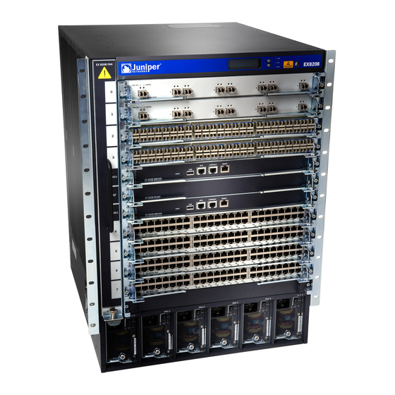
Juniper EX8208 Hardware Manual
Hide thumbs
Also See for EX8208:
- Complete hardware manual (344 pages) ,
- Instruction (3 pages) ,
- Installation & removal instructions (3 pages)
Table of Contents
Advertisement
Quick Links
Advertisement
Table of Contents
Troubleshooting

Related Manuals for Juniper EX8208


Summary of Contents for Juniper EX8208
- Page 1 EX8208 Switch Hardware Guide Published 2020-12-15...
- Page 2 END USER LICENSE AGREEMENT The Juniper Networks product that is the subject of this technical documentation consists of (or is intended for use with) Juniper Networks software. Use of such software is subject to the terms and conditions of the End User License Agreement (“EULA”) posted at https://support.juniper.net/support/eula/.
-
Page 3: Table Of Contents
Cooling System | 25 Power Supplies | 26 EX8208 Switch Configurations | 27 EX8208 Switch Hardware and CLI Terminology Mapping | 29 Chassis Physical Specifications of an EX8208 Switch | 33 Field-Replaceable Units in an EX8208 Switch | 35 EX8208 Chassis | 37... - Page 4 Grounding Cable and Lug Specifications for EX8200 Switches | 76 EX8208 Host Subsystem | 78 Switch Fabric and Routing Engine (SRE) Module in an EX8208 Switch | 78 SRE Module LEDs in an EX8208 Switch | 80 Switch Fabric (SF) Module in an EX8208 Switch | 81...
- Page 5 EX8200 Line Cards | 83 Line Card Model and Version Compatibility in an EX8200 Switch | 84 8-port SFP+ Line Card in an EX8200 Switch | 86 Line Card Models | 87 Line Card Components | 87 40-port SFP+ Line Card in an EX8200 Switch | 88 Line Card Models | 89 Line Card Components | 90 Line Card Ports | 90...
- Page 6 Environmental Requirements and Specifications for EX Series Switches | 110 General Site Guidelines | 115 Site Electrical Wiring Guidelines | 115 Clearance Requirements for Airflow and Hardware Maintenance for an EX8208 Switch | 116 Rack Requirements | 118 Cabinet Requirements | 119...
- Page 7 Mounting an EX8208 Switch on a Rack or Cabinet | 154 Mounting an EX8208 Switch on a Rack or Cabinet Using a Mechanical Lift | 157 Mounting an EX8208 Switch on a Rack or Cabinet Without Using a Mechanical Lift | 159 Connecting the EX8200 to Power | 164...
- Page 8 Chassis Viewer | 216 Maintaining Components Maintaining the EX8208 Cooling System | 235 Removing a Fan Tray from an EX8208 Switch | 235 Installing a Fan Tray in an EX8208 Switch | 237 Maintaining the EX8200 Power System | 238...
- Page 9 Removing an EX8208 Switch from a Rack or Cabinet Using a Mechanical Lift | 292 Removing an EX8208 Switch from a Rack or Cabinet Without Using a Mechanical Lift | 294 Removing a Battery from an EX8208 Switch for Recycling | 296...
- Page 10 Troubleshooting Hardware Troubleshooting EX8200 Components | 299 Understand Alarm Types and Severity Levels on EX Series Switches | 299 Chassis Component Alarm Conditions on EX8200 Switches | 300 Check Active Alarms with the J-Web Interface | 311 Monitor System Log Messages | 312 Troubleshooting an EX8200 Line Card’s Failure to Power On | 317 Troubleshoot Temperature Alarms in EX Series Switches | 320 Contacting Customer Support and Returning the Chassis or Components...
- Page 11 Restricted Access Warning | 356 Ramp Warning | 358 Rack-Mounting and Cabinet-Mounting Warnings | 359 Grounded Equipment Warning | 365 Radiation from Open Port Apertures Warning | 366 Laser and LED Safety Guidelines and Warnings | 367 General Laser Safety Guidelines | 367 Class 1 Laser Product Warning | 368 Class 1 LED Product Warning | 369 Laser Beam Warning | 370...
- Page 12 TN Power Warning | 397 Agency Approvals for EX Series Switches | 397 Battery Compliance Statement for Environmental Requirements for EX Series Switches | 398 Compliance Statements for EMC Requirements for EX Series Switches | 399 Canada | 399 Taiwan | 400 European Community | 400 Israel | 401 Japan | 401...
-
Page 13: About The Documentation
Use this guide to install hardware and perform initial software configuration, routine maintenance, and troubleshooting for the EX8208 switch. After completing the installation and basic configuration procedures covered in this guide, refer to the Junos OS documentation for information about further software configuration. -
Page 14: Merging A Full Example
If the example configuration contains the top level of the hierarchy (or multiple hierarchies), the example is a full example. In this case, use the load merge command. If the example configuration does not start at the top level of the hierarchy, the example is a snippet. In this case, use the load merge relative command. -
Page 15: Merging A Snippet
Merging a Snippet To merge a snippet, follow these steps: 1. From the HTML or PDF version of the manual, copy a configuration snippet into a text file, save the file with a name, and copy the file to a directory on your routing platform. For example, copy the following snippet to a file and name the file ex-script-snippet.conf. - Page 16 Table 1: Notice Icons Icon Meaning Description Informational note Indicates important features or instructions. Caution Indicates a situation that might result in loss of data or hardware damage. Warning Alerts you to the risk of personal injury or death. Laser warning Alerts you to the risk of personal injury from a laser.
- Page 17 xvii Table 2: Text and Syntax Conventions (continued) Convention Description Examples Italic text like this Represents variables (options for Configure the machine’s domain which you substitute a value) in name: commands or configuration [edit] statements. root@# set system domain-name domain-name Text like this Represents names of configuration To configure a stub area, include...
-
Page 18: Documentation Feedback
URL or page number, and software version (if applicable). Requesting Technical Support Technical product support is available through the Juniper Networks Technical Assistance Center (JTAC). If you are a customer with an active Juniper Care or Partner Support Services support contract, or are... -
Page 19: Self-Help Online Tools And Resources
JTAC hours of operation—The JTAC centers have resources available 24 hours a day, 7 days a week, 365 days a year. Self-Help Online Tools and Resources For quick and easy problem resolution, Juniper Networks has designed an online self-service portal called the Customer Support Center (CSC) that provides you with the following features: Find CSC offerings: https://www.juniper.net/customers/support/... - Page 20 C HAPTER EX8208 System Overview EX8208 System Overview | 21 EX8208 Chassis | 37 EX8208 Cooling System | 53 EX8200 Power System | 56 EX8208 Host Subsystem | 78 EX8200 Line Cards | 83...
-
Page 21: Ex8208 System Overview
The EX8208 switch is a modular system that provides high availability and redundancy for all major hardware components, including Routing Engines, switch fabric, fan tray (redundant fans), and power supplies. -
Page 22: Benefits Of The Ex8208 Switch
Chassis Physical Specifications, LCD Panel, and Backplane The EX8208 switch is 14 rack units (14 U) in size (1/3 rack). Three EX8208 switches can fit in a standard 42 U rack. Each EX8208 switch is designed to optimize rack space and cabling. See... -
Page 23: Routing Engines And Switch Fabric
Lift handle supplies The EX8208 switch has a chassis-level LCD panel that displays Routing Engine and switch fabric status as well as chassis components’ alarm information for rapid problem identification. The LCD panel provides a user-friendly interface for performing initial switch configuration, rolling back a configuration, or restoring the switch to its default settings. -
Page 24: Line Cards
The Switch Fabric (SF) module, working with the SRE module, provides the necessary switching functionality to a base configuration EX8208 switch. The SF module is installed in the front of the chassis in the slot labeled SF. In a redundant configuration, the SF module provides full 2+1 switch fabric redundancy to the switch. -
Page 25: Cooling System
Cooling System The cooling system in an EX8208 switch consists of a hot-removable and hot-insertable FRU fan tray. The fan tray contains 12 fans. The fan tray installs vertically on the left front of the chassis and provides side-to-side chassis cooling. -
Page 26: Power Supplies
Power Supplies Power supplies for the EX8208 switch are fully redundant, load-sharing, and hot-removable and hot-insertable (FRUs. Each EX8208 switch chassis can hold up to six AC or DC power supplies. Table 4 on page 26 shows the details of the power supplies available for EX8208 switches. -
Page 27: Ex8208 Switch Configurations
EX8208 Switch Configurations Table 5 on page 27 lists the seven sample hardware configurations for an EX8208 switch—base (AC), redundant (AC and DC versions), and fully loaded chassis (AC and DC versions)—and the components included in each configuration. The switch is shipped in only four of these seven configurations: base (AC with 2000 W AC power supplies), base (AC with 3000 W AC power supplies), redundant (AC with 2000 W AC power supplies), and redundant (DC). - Page 28 Table 5: EX8208 Switch Hardware Configurations (continued) Switch Configuration Configuration Components Redundant configuration (DC) Chassis with backplane One fan tray Two SRE modules One SF module Four 2000 W DC power supplies 16 DC power cable lugs Eight line card cover panels...
-
Page 29: Ex8208 Switch Hardware And Cli Terminology Mapping
EX8208 Switch Hardware and CLI Terminology Mapping This topic describes the hardware terms used in EX8208 switch documentation and the corresponding terms used in the Junos OS command line interface (CLI). See Table 6 on page... - Page 30 Table 6: CLI Equivalents of Terms Used in Documentation for EX8208 Switches (continued) Hardware Item In Item (CLI) Description (CLI) Value (CLI) Documentation Additional Information CB (n) One of the n is a value in the range The switch does not following: of 0–2.
- Page 31 Table 6: CLI Equivalents of Terms Used in Documentation for EX8208 Switches (continued) Hardware Item In Item (CLI) Description (CLI) Value (CLI) Documentation Additional Information FPC (n) On EX8200 n is a value in the range Line card (The switch...
- Page 32 Table 6: CLI Equivalents of Terms Used in Documentation for EX8208 Switches (continued) Hardware Item In Item (CLI) Description (CLI) Value (CLI) Documentation Additional Information LCD (n) EX8200 LCD Value of n is always 0. LCD panel LCD Panel in an EX8200...
-
Page 33: Chassis Physical Specifications Of An Ex8208 Switch
Chassis Physical Specifications of an EX8208 Switch The EX8208 switch chassis is a rigid sheet-metal structure that houses the other switch components. Table 7 on page 33 summarizes the physical specifications of the EX8208 switch chassis. See Figure 2 on page... - Page 34 You can mount an EX8200 switch on a standard 19-in. four-post rack or a standard 800-mm enclosed cabinet. Up to three EX8208 switches can be installed in a standard (42 rack unit (U)) rack provided the rack can handle their combined weight.
-
Page 35: Field-Replaceable Units In An Ex8208 Switch
Do not use the lift handles to lift the chassis unless the chassis is empty (that is, contains only the backplane). Failure to heed this warning can result in injury. “Mounting an EX8208 Switch on a Rack or Cabinet Using a Mechanical Lift” on page 157 “Mounting an EX8208 Switch on a Rack or Cabinet Without Using a... - Page 36 Line cards are not part of the base or redundant configuration. You must order them separately. NOTE: If you have a Juniper J-Care service contract, register any addition, change, or upgrade of hardware components at https://www.juniper.net/customers/support/tools/updateinstallbase/ . Failure to do so can result in significant delays if you need replacement parts.
-
Page 37: Ex8208 Chassis
Switch Fabric Redundancy | 39 The Juniper Networks EX8208 Ethernet Switch is available as a fully redundant system. A redundant EX8208 switch configuration is designed so that no single point of failure can cause the entire switch to fail. See “EX8208 Switch Configurations”... -
Page 38: Routing Engine And Control Redundancy
Power supplies—You can install up to six AC or six DC power supplies in an EX8208 switch. Each power supply connects to the backplane of the chassis, which distributes the output power produced by the power supplies to different switch components. -
Page 39: Switch Fabric Redundancy
Switch Fabric Redundancy The switch fabric circuitry in an EX8208 switch is distributed across three modules—two SRE modules and one SF module. Any two of these three modules must be installed and functional to provide a working switch fabric with no redundancy. The third module, when present, provides partial redundancy (2+1) for the switching functionality, such that if any one of the two functional modules becomes nonoperational, the third module takes over. -
Page 40: Slot Numbering For An Ex8208 Switch
Slot Numbering for the Power Supply Slots | 42 An EX8208 chassis accepts eight line cards, two Switch Fabric and Routing Engine (SRE) modules, one Switch Fabric (SF) module, one fan tray, and six power supplies (AC or DC). All 11 slots for the line cards and the modules run horizontally across the front of the chassis. - Page 41 Table 11: Slot Numbering for an EX8208 Switch (continued) Slot Label Components Accepted in Slot Line card Figure 3 on page 41 shows the slot numbering, which is on the front left of the chassis. Figure 3: Slot Numbering for an EX8208 Switch...
-
Page 42: Slot Numbering For The Power Supply Slots
“Switch Fabric (SF) Module in an EX8208 Switch” on page 81. An EX8208 switch can have either zero SF modules or one SF module based on your switch configuration. The SF module is keyed so that it does not fit in any other slot in the chassis. See “Installing an SF Module... -
Page 43: Lcd Panel In An Ex8200 Switch
Figure 4: Slot Numbering for Power Supply Slots on an EX8208 Switch Chassis Front NOTE: Power supplies can be installed in any slot. You do not have to install them in serial order. “Installing an AC Power Supply in an EX8200 Switch” on page 240 “Installing a DC Power... -
Page 44: Lcd Panel Modes
The status mode allows you to get status information for the following items: Switch fabric in Switch Fabric and Routing Engine (SRE) modules in EX8208 switches Routing Engine (RE) and switch fabric in Switch Fabric (SF) module(s) in EX8216 switches... -
Page 45: Lcd Panel Menus
LCD Panel Menus The LCD panel has three menus: Idle, Status, and Maintenance. In each of these menus, line one of the LCD panel displays the hostname of the switch. Toggle between the LCD menus by pressing the Menu button. Navigate through the menu options by pressing the Enter button. Table 13 on page 45 describes the LCD panel menu options. - Page 46 Press Enter to display the status of the switch fabric in the SRE modules (SRE0 and SRE1) in EX8208 switches and the SF modules (SF) in EX8216 switches: OK, Fld (failed), ABS (absent) Press Menu to go to the next option in the Status menu.
- Page 47 Table 13: LCD Panel Menu Options for the EX8200 Switch (continued) Menu Description Maintenance...
- Page 48 The Maintenance menu has the following options: SYSTEM HALT?—Choose one of the following: Press Enter to halt the primary SRE module in an EX8208 switch or to halt the primary RE module in an EX8216 switch. Press Enter again to confirm the halt.
-
Page 49: Backplane In An Ex8208 Switch
Connecting and Configuring an EX Series Switch (CLI Procedure) | 194 Connecting and Configuring an EX Series Switch (J-Web Procedure) | 198 Backplane in an EX8208 Switch The backplane is a printed circuit board that forms the back of the line card cage. The Switch Fabric and Routing Engine (SRE) modules, Switch Fabric (SF) module, power supplies, and line cards plug into the backplane from the front of the chassis. -
Page 50: Chassis Status Leds In An Ex8200 Switch
Chassis Status LEDs in an EX8200 Switch The top front of the chassis of an EX8200 switch has three LEDs on the right side of the LCD panel. Figure 6 on page Figure 6: Chassis Status LEDs Table 14 on page 50 describes the chassis status LEDs in an EX8200 switch, their colors and states, and the status they indicate. -
Page 51: Network Port Leds In An Ex8200 Switch
SEE ALSO Chassis Component Alarm Conditions on EX8200 Switches | 300 Understand Alarm Types and Severity Levels on EX Series Switches | 299 Network Port LEDs in an EX8200 Switch Each network port on the faceplate of a line card has two LEDs. Figure 7 on page 51 shows the network port LEDs on the line cards. - Page 52 Table 16: Network Port LEDs on Line Cards in an EX8200 Switch—Status LED LCD Indicator State, Color, and Description Status LED: ADM Indicates the administrative status (enabled or disabled). The status indicators are: Green—Administrative status enabled. Yellow—The port is down. Unlit—Administrative status disabled.
-
Page 53: Ex8208 Cooling System
Unlit—PoE is not enabled on the port. SEE ALSO Line Card LEDs in an EX8200 Switch | 105 EX8208 Cooling System IN THIS SECTION Fan Tray | 54 Airflow Direction in the EX8208 Switch Chassis | 55... -
Page 54: Fan Tray
The cooling system in an EX8208 switch consists of a single fan tray. Fan Tray The fan tray is a hot-insertable and hot-removable field-replaceable unit (FRU). The fan tray contains 12 fans. The fan tray installs vertically on the left side on the front of the chassis and provides side-to-side chassis cooling. -
Page 55: Airflow Direction In The Ex8208 Switch Chassis
See Figure 9 on page Figure 9: Airflow Through the EX8208 Switch Chassis The Switch Fabric and Routing Engine (SRE) module monitors the temperature of switch components. Under normal operating conditions, the fans in the fan tray run at less than full speed. The fans are controlled by two fan tray controllers. -
Page 56: Ex8200 Power System
There is no fan guard on the fans. Be careful to keep your fingers clear of moving fan blades when you are removing the fan tray. RELATED DOCUMENTATION Clearance Requirements for Airflow and Hardware Maintenance for an EX8208 Switch | 116 EX8200 Power System IN THIS SECTION... -
Page 57: Ac Power Supply Description
For details about different switch configurations, see “EX8208 Switch Configurations” on page 27 or EX8216 Switch Configurations. Each AC power supply weighs approximately 7 lb (3.2 kg) and has an independent 16 A rated AC inlet on the faceplate. - Page 58 Figure 11: Power Cord Retainer for an AC Power Supply Each power supply connects to the backplane in an EX8208 switch and to the midplane in an EX8216 switch. The backplane and the midplane distribute the output power produced by the power supplies to different switch components.
-
Page 59: N+1 Redundancy Configuration Of Ac Power Supplies
EX8216 Switch Configurations. The tables in this section list the N+1 power requirements for different EX8200 switch configurations: Table 17 on page 59—Lists the N+1 power requirements of EX8208 switch configurations that use 2000 W AC power supplies. Table 18 on page 60—Lists the N+1 power requirements of EX8208 switch configurations that use 3000... -
Page 60: N+N Redundancy Configuration Of Ac Power Supplies
Table 18: N+1 Power Redundancy Configurations for Different EX8208 Switch Configurations Using 3000 W AC Power Supplies Power Supplies Power Supplies Needed for N+1 Switch Configuration Input Voltage Needed (N) Redundancy Base High-voltage line (200–240 VAC) Fully loaded with 8-port High-voltage line (200–240 VAC) - Page 61 EX8216 Switch Configurations. The tables in this section list the N+N power requirements for different EX8200 switch configurations: Table 21 on page 62—Lists the N+N power requirements of EX8208 switch configurations that use 2000 W AC power supplies. Table 22 on page 62—Lists the N+N power requirements of EX8208 switch configurations that use...
- Page 62 Table 21: N+N Power Supply Requirements for EX8208 Switch Configurations Using 2000 W AC Power Supplies (Junos OS Release 10.2 or Later Only) Power Supplies Power Supplies Needed for N+N Switch Configuration Input Voltage Needed (N) Redundancy Base High-voltage line (200–240 VAC) Low-voltage line (100–120 VAC)
-
Page 63: Ac Power Supply Leds In An Ex8200 Switch
Table 24: N+N Power Supply Requirements for EX8216 Switch Configurations Using 3000 W AC Power Supplies (Junos OS Release 10.2 or Later Only) Power Supplies Switch Power Supplies Needed for N+N Configuration Input Voltage Needed (N) Redundancy Base High-voltage line (200–240 VAC) Fully loaded with High-voltage line (200–240 VAC) 8-port SFP+ line... - Page 64 Table 25: Power Supply LEDs on EX8200 Switches State Description INPUT OK Unlit Indicates one of the following: Power supply is disconnected from AC power feed. AC power input voltage is not within normal operating range. No AC power input. Green AC power input is high-voltage line (200–240 VAC).
-
Page 65: Ac Power Specifications For Ex8200 Switches
NOTE: If the INPUT OK LED and the OUTPUT OK LED are unlit, the AC power cord is not installed properly or the power supply has failed. If the INPUT OK LED is lit and the OUTPUT OK LED is unlit, the AC power supply is not installed properly or the power supply has an internal failure. -
Page 66: Ac Power Cord Specifications For An Ex8200 Switch
Table 27: Power Specifications for a 3000 W AC Power Supply in an EX8200 Switch Item Specifications AC input voltage Operating range: High-voltage line—200–240 VAC NOTE: Low-voltage line input is not supported for 3000 W AC power supplies on the EX8216 switch. AC input line frequency 50–60 Hz AC input current rating... - Page 67 Table 28: AC Power Cord Specifications for an EX8200 Switch Electrical Country/Region Specifications Plug Standards Juniper Model Number Graphic Argentina 250 VAC, 16 A, 50 Hz IRAM Type RA/3/20 CBL-EX-PWR-C19-AR graphic available. Australia 250 VAC, 15 A, 50 Hz AS/NZS 3112 Type...
- Page 68 Table 28: AC Power Cord Specifications for an EX8200 Switch (continued) Electrical Country/Region Specifications Plug Standards Juniper Model Number Graphic Israel 250 VAC, 16 A, 50 Hz SI 32/1971 Type IL/3 CBL-EX-PWR-C19-IL Italy 250 VAC, 16 A, 50 Hz CEI 23-16 Type I/3/16...
- Page 69 Table 28: AC Power Cord Specifications for an EX8200 Switch (continued) Electrical Country/Region Specifications Plug Standards Juniper Model Number Graphic Taiwan 250 VAC, 16 A, 50 Hz NEMA L6-20P Type NEMA CBL-EX-PWR-C19-TW LOCKING United Kingdom 250 VAC, 13 A, 50 Hz...
-
Page 70: Dc Power Supply In An Ex8200 Switch
The DC power supplies in EX8200 switches are hot-removable and hot-insertable field-replaceable units (FRUs). NOTE: EX8208 switches support 2000 W DC power supplies. EX8216 switches support 3000 W DC power supplies. You can install up to six DC power supplies in an EX8200 switch. Power supplies are installed at the bottom of the chassis in slots labeled PSU 0 through PSU 5 (left to right). - Page 71 A 3000 W DC power supply requires a dedicated 100 A circuit breaker for each input DC feed. Each DC power supply connects to the backplane in an EX8208 switch and to the midplane in an EX8216 switch. The backplane in an EX8208 switch and the midplane in an EX8216 switch distribute the output power produced by the power supplies to different switch components.
-
Page 72: Dc Power Supply Leds In An Ex8200 Switch
The tables in this section list the N+1 power requirements of different EX8200 switch configurations: Table 29 on page 72—Lists the N+1 power requirements of EX8208 switch configurations that use 2000 W DC power supplies. Table 30 on page 72—Lists the N+1 power requirements of EX8216 switch configurations that use 3000 W DC power supplies. - Page 73 Figure 14: DC Power Supply LEDs in an EX8200 Switch Table 31 on page 73 describes the LEDs on a DC power supply in EX8200 switches. Table 31: DC Power Supply LEDs in EX8200 Switches State Description A IN OK Unlit Indicates one of the following: Power supply is disconnected from DC power...
- Page 74 Table 31: DC Power Supply LEDs in EX8200 Switches (continued) State Description B IN OK Unlit Indicates one of the following: Power supply is disconnected from DC power feed. DC power input voltage is not within normal operating range (-40 VDC through -72 VDC). No DC power input.
-
Page 75: Dc Power Specifications For Ex8200 Switches
75 A maximum at nominal operating voltage (–48 VDC) for each input terminal. Output power 3000 W Internal Fuse Protection 100 A Table 33 on page 76 lists the power specifications for the 2000 W DC power supply used in EX8208 switches. -
Page 76: Grounding Cable And Lug Specifications For Ex8200 Switches
Table 33: Power Specifications for a 2000 W DC Power Supply Used in an EX8208 Switch Item Specifications DC input voltage Minimum operating voltage: –40 VDC Nominal operating voltage: –48 VDC Operating voltage range: –40 VDC through –72 VDC NOTE: If the input voltage from the DC power source drops below –37.5 VDC through... - Page 77 Grounding requirements for EX8200 switches: EX8208 switches—A pair of threaded inserts (PEM nuts) is provided on the right side toward the top rear corner of the EX8208 chassis for connecting the switch to earth ground. The grounding points fit UNC ¼-20 screws. The grounding points are spaced at 0.625 in. (15.86 mm).
-
Page 78: Ex8208 Host Subsystem
The Switch Fabric and Routing Engine (SRE) module performs switching and system management functions in an EX8208 switch. See Figure 16 on page You can install one or two SRE modules in an EX8208 switch. A base configuration EX8208 switch has only one SRE module. See “EX8208 Switch Configurations” on page 27. - Page 79 The SRE module has these components: SRE module LEDs—Indicate system status. See “SRE Module LEDs in an EX8208 Switch” on page Recessed reset button—Power cycles the SRE module when pressed. Take the SRE module offline using the CLI before pressing the reset button. See “Taking the SRE Module...
-
Page 80: Sre Module Leds In An Ex8208 Switch
Figure 17 on page Table 34 on page 80 describes these LEDs, their colors and states, and the status they indicate. Figure 17: SRE Module LEDs in an EX8208 Switch Table 34: SRE Module LEDs of an EX8208 Switch LED Label (Description) Color... -
Page 81: Switch Fabric (Sf) Module In An Ex8208 Switch
The Switch Fabric (SF) module provides switching functionality. See Figure 18 on page An EX8208 switch can have either zero SF modules or one SF module. The base configuration of an EX8208 switch includes one SF module. See “EX8208 Switch Configurations” on page Figure 18: SF Module in an EX8208 Switch The SF module can be installed only in the slot labeled SF. -
Page 82: Sf Module Leds In An Ex8208 Switch
SF module is to provide a redundant switching plane for the switch. “Understanding EX8208 Switch Component and Functionality Redundancy” on page In a redundant configuration, the SF module is hot-pluggable. However, in the base configuration, you must take the SF module offline before removing it. -
Page 83: Ex8200 Line Cards
Table 35: SF Module LEDs of an EX8208 Switch LED (Description) Color State and Description ST (Status) Green On steadily—SF module is operating normally. Blinking—Waiting to be configured by the primary Switch Fabric and Routing Engine (SRE) module. Yellow SF module has failed. -
Page 84: Line Card Model And Version Compatibility In An Ex8200 Switch
Line Card Model and Version Compatibility in an EX8200 Switch Twelve line cards are available for EX8200 switches. The extra-scale line card models, identified by the letters ES at the end of the model names, provide larger IPv4 and IPv6 route table than the non-extra-scale models to store more unicast routes. - Page 85 Table 36: Line Card Models by Junos OS Release (continued) Support on First EX8200 EX8200 Virtual Junos OS Virtual Chassis Port Model Number Name Release Chassis (VCP) Support EX8200-48F-ES 48-port SFP line card, extra-scale 11.1R1 11.4R1 Not supported Table 37 on page 85 shows the model numbers, associated hardware revisions, and the required Junos OS release for the EX8200 line cards that are shipped after August 7, 2015.
-
Page 86: 8-Port Sfp+ Line Card In An Ex8200 Switch
NOTE: We recommend that you do not install extra-scale line card models and non-extra-scale models in the same switch or Virtual Chassis. If you install extra-scale line cards in a switch or Virtual Chassis that has non-extra-scale models installed, the IPv4 and IPv6 route table sizes default to those of the non-extra-scale models and you will not get the benefit of the increased table sizes of the extra-scale models. -
Page 87: Line Card Models
NOTE: Figure 20 on page 86 shows a line card that has 2-in.-long ejector levers. An earlier version of this line card has 4-in.-long ejector levers. Line Card Models Table 38 on page 87 shows the model numbers, descriptions of the line card models, the Junos OS release in which the models were released, the release in which support on EX8200 Virtual Chassis was introduced, and the release in which Virtual Chassis Port (VCP) support was introduced for ports on the line card. -
Page 88: 40-Port Sfp+ Line Card In An Ex8200 Switch
Eight 10-gigabit SFP+ ports, which can house SFP+ transceivers NOTE: The 10-Gigabit Ethernet ports on the 8-port SFP+ line cards are the only ports that you can configure as Virtual Chassis port (VCP) links between EX8200 member switches in an EX8200 Virtual Chassis. -
Page 89: Line Card Models
Figure 21: 40-port SFP+ Line Card Network ports Line card LEDs EX8 200- 40X S Ejector lever Ejector lever Captive screw Line Card Models Table 39 on page 89 shows the model numbers, description of the line card models, the Junos OS release in which the line card was released, the release in which support on EX8200 Virtual Chassis was introduced, and the release in which Virtual Chassis Port (VCP) support was introduced for ports on the line card. -
Page 90: Line Card Components
NOTE: We recommend that you do not install extra-scale line card models and non-extra-scale models in the same switch or Virtual Chassis. If you install extra-scale line cards in a switch or Virtual Chassis that has non-extra-scale models installed, the IPv4 and IPv6 route table sizes default to those of the non-extra-scale models and you will not get the benefit of the increased table sizes of the extra-scale models. - Page 91 Table 40: Port Numbers and Port Groups on a 40-port SFP+ Line Card (continued) Port Number Group Number 25 through 29 30 through 34 35 through 39 Figure 22: Port Numbering and Port Groups on a 40-port SFP+ Line Card Group 0 Group 2 Group 4...
-
Page 92: Ex8200-2Xs-40P Line Card
EX8200-2XS-40P Line Card IN THIS SECTION Line Card Models | 92 Line Card Components | 93 Line Card Ports | 93 The line cards in EX8200 switches combine a Packet Forwarding Engine and Ethernet interfaces on a single assembly. They are field-replaceable units (FRUs) that can be installed in the line card slots on the front of the switch chassis. -
Page 93: Line Card Components
Table 41: EX8200-2XS-40P Line Card Models Junos OS Support on Release EX8200 Virtual EX8200 Virtual Chassis Model Description Required Chassis Port (VCP) Support EX8200-2XS-40P 40-port PoE+ with 11.2R1 or later 11.4R1 11.4R1 4-port SFP and 2-port NOTE: VCPs supported on SFP+ line card SFP+ transceivers only Line Card Components... -
Page 94: Ex8200-2Xs-40T Line Card
Table 42: Ports on the EX8200-2XS-40P Line Card (continued) Port Number Port Type Throughput Additional Information 44 and 45 SFP+ Line rate Can be used as an uplink of 10-Gigabit Ethernet fiber links in a link aggregation group (LAG). The ports are divided into two port groups: The RJ-45 ports 0–19 and SFP ports 40 and 41 form one port group. -
Page 95: Line Card Models
of the switch chassis. The line cards are hot-insertable and hot-removable: You can remove and replace them without powering off the switch or disrupting switch functions. The EX8200-2XS-40T (40-port RJ-45 with 4-port SFP and 2-port SFP+) line card offers maximum port density for the access layer and SFP and SFP+ uplink ports for connection to the distribution layer (see Figure 24 on page 95). -
Page 96: Line Card Ports
Line card status LEDs—Two status LEDs labeled ON and ST that indicate the online and status for the line card. See “Line Card LEDs in an EX8200 Switch” on page 105. Network port LEDs—Two LEDs per network port that indicate the link/activity and status of each port. See Network Port LEDs in an EX8200 Switch. -
Page 97: Ex8200-48Pl Line Card
For more information about using these ports: To understand how traffic is handled by oversubscribed ports, see Understanding CoS Queues on EX8200 Line Cards That Include Oversubscribed Ports. EX8200-48PL Line Card IN THIS SECTION Line Card Models | 97 Line Card Components | 98 Line Card Ports | 98 The line cards in EX8200 switches combine a Packet Forwarding Engine and Ethernet interfaces on a single assembly. -
Page 98: Line Card Components
Table 45: EX8200-48PL Line Card Models Junos OS Release Support on EX8200 EX8200 Virtual Chassis Model Description Required Virtual Chassis Port (VCP) Support EX8200-48PL 48-port PoE+ 20 11.2R1 or later 11.4R1 Not supported Gbps line card Line Card Components The EX8200-48PL line card (see Figure 25 on page 97) has: 48 oversubscribed RJ-45 ports (PoE-enabled or PoE+-enabled) -
Page 99: Ex8200-48Tl Line Card
The ports in each group share 10 gigabits of bandwidth. You can transmit up to 10 gigabits of traffic through a port group without packet drop. The oversubscription ratios of different port groups can differ from one another; the ratios depend on the amount of traffic being transmitted through a port group. For more information about using these ports: To understand how traffic is handled by oversubscribed ports, see Understanding CoS Queues on EX8200 Line Cards That Include Oversubscribed Ports. -
Page 100: Line Card Models
Figure 26: EX8200-48TL Line Card RJ-45 ports EX8200-48TL Line card LEDs Line Card Models Table 47 on page 100 shows the model number, description of the line card model, the Junos OS release in which the model was released, the release in which support on EX8200 Virtual Chassis was introduced, and the release in which Virtual Chassis Port (VCP) support was introduced for ports on the line card. -
Page 101: 48-Port Sfp Line Card In An Ex8200 Switch
The ports are divided into two port groups: The ports 0 through 23 form one port group. The ports 24 through 47 form another port group. The ports in each group share 10 gigabits of bandwidth. You can transmit up to 10 gigabits of traffic through a port group without packet drop. -
Page 102: Line Card Models
NOTE: Figure 27 on page 101 shows a line card that has 2-in.-long ejector levers. An earlier version of this line card has 4-in.-long ejector levers. Line Card Models Table 49 on page 102 shows the model numbers, descriptions of the line card models, the Junos OS release in which the models were released, the release in which support on EX8200 Virtual Chassis was introduced, and the release in which Virtual Chassis Port (VCP) support was introduced for ports on the line card. -
Page 103: 48-Port Rj-45 Line Card In An Ex8200 Switch
48 1-gigabit SFP ports, which can house SFP transceivers 48 dust covers (in an accessory bag) Line card status LEDs—Two status LEDs labeled ON and ST that indicate the online and status information for the line card. See “Line Card LEDs in an EX8200 Switch” on page 105. -
Page 104: Line Card Models
Line Card Models Table 50 on page 104 shows the model numbers, descriptions of the line card models, the Junos OS release in which the models were released, the release in which support on EX8200 Virtual Chassis was introduced, and the release in which Virtual Chassis Port (VCP) support was introduced for ports on the line card. Table 50: 48-port RJ-45 Line Card Models Junos OS Support on... -
Page 105: Line Card Leds In An Ex8200 Switch
Network port LEDs—Two LEDs per network port indicate the link/activity and status of each port. See Network Port LEDs in an EX8200 Switch. Line Card LEDs in an EX8200 Switch The line cards in EX8200 switches have two status LEDs labeled ON and ST on the faceplate (see Figure 29 on page 105) that indicate the online and status information of the line cards. - Page 106 Table 51: Status LEDs on Line Cards for EX8200 Switches (continued) Color State and Description Green On steadily—PoE on the line card is functioning normally. NOTE: This LED is Yellow On steadily—PoE is not functioning normally. present only on EX8200-2XS-40P Unlit Line card is booting up.
-
Page 107: Site Planning, Preparation, And Specifications
C HAPTER Site Planning, Preparation, and Specifications Site Preparation Checklist for an EX8200 Switch | 108 EX8208 Site Guidelines and Requirements | 109 EX8200 Network Cable and Transceiver Planning | 128 EX8200 Management Cable Specifications and Pinouts | 135... -
Page 108: Site Preparation Checklist For An Ex8200 Switch
“Power Requirements for EX8208 Switch Components” on page 120 Power Requirements for EX8216 Switch Components “Calculating Power Requirements for an EX8208 Switch” on page 121 Calculating Power Requirements for an EX8216 Switch “Calculating the Fiber-Optic Cable Power Budget for EX Series Devices”... -
Page 109: Ex8208 Site Guidelines And Requirements
Ensure that the distance between hardware components to be connected allows for cable lengths to be within the specified maximum limits. EX8208 Site Guidelines and Requirements IN THIS SECTION Environmental Requirements and Specifications for EX Series Switches | 110 General Site Guidelines | 115... -
Page 110: Environmental Requirements And Specifications For Ex Series Switches
Clearance Requirements for Airflow and Hardware Maintenance for an EX8208 Switch | 116 Rack Requirements | 118 Cabinet Requirements | 119 Power Requirements for EX8208 Switch Components | 120 Calculating Power Requirements for an EX8208 Switch | 121 Environmental Requirements and Specifications for EX Series Switches The switch must be installed in a rack or cabinet housed in a dry, clean, well-ventilated, and temperature-controlled environment. -
Page 111: Switch Or Device Altitude
Table 53: EX Series Switch Environmental Tolerances (continued) Environment Tolerance Switch or device Altitude Relative Humidity Temperature Seismic EX2200 No performance Normal operation ensured Normal operation ensured Complies with Zone (except degradation up to in the relative humidity in the temperature range 4 earthquake EX2200-C 10,000 feet... - Page 112 Table 53: EX Series Switch Environmental Tolerances (continued) Environment Tolerance Switch or device Altitude Relative Humidity Temperature Seismic EX4300 EX4300 switches EX4300 switches except Normal operation ensured Complies with Zone except the the EX4300-48MP in the temperature range 4 earthquake EX4300-48MP model—...
- Page 113 10% through 85% 32° F (0° C) through 104° requirements as per (3048 meters) (noncondensing) F (40° C) GR-63, Issue 4. EX8208 No performance Normal operation ensured Normal operation is ensured Complies with Zone degradation up to in the relative humidity...
- Page 114 Table 53: EX Series Switch Environmental Tolerances (continued) Environment Tolerance Switch or device Altitude Relative Humidity Temperature Seismic EX9204 No performance Normal operation ensured Normal operation is ensured Complies with Zone degradation up to in the relative humidity in the temperature range 4 earthquake 10,000 feet range 5% through 90%...
-
Page 115: General Site Guidelines
Table 53: EX Series Switch Environmental Tolerances (continued) Environment Tolerance Switch or device Altitude Relative Humidity Temperature Seismic XRE200 No performance Normal operation ensured Normal operation ensured Complies with Zone degradation up to in the relative humidity in the temperature range 4 earthquake 10,000 feet range 10% through 85%... -
Page 116: Clearance Requirements For Airflow And Hardware Maintenance For An Ex8208 Switch
Electrical hazards as a result of power surges conducted over the lines into the equipment Clearance Requirements for Airflow and Hardware Maintenance for an EX8208 Switch When planning the site for installing an EX8208 switch, you must allow sufficient clearance around the switch. - Page 117 Figure 30 on page 117. Figure 30: Airflow Through the EX8208 Switch Chassis If you are mounting the switch on a rack or cabinet along with other equipment, ensure that the exhaust from other equipment does not blow into the intake vents of the chassis.
-
Page 118: Rack Requirements
Figure 31: Clearance Requirements for Airflow and Hardware Maintenance for an EX8208 Switch Chassis SEE ALSO EX8208 Cooling System | 53 Rack Requirements You can mount the device on two-post racks or four-post racks. Rack requirements consist of: Rack type... -
Page 119: Cabinet Requirements
Table 55: Rack Requirements and Specifications Rack Requirement Guidelines Rack type You can mount the device on a rack that provides bracket holes or hole patterns spaced at 1-U (1.75 in. or 4.45 cm) increments and meets the size and strength requirements to support the weight. -
Page 120: Power Requirements For Ex8208 Switch Components
A cabinet larger than the minimum required provides better airflow and reduces the chance of overheating. Power Requirements for EX8208 Switch Components Table 57 on page 120 lists the power requirements for different hardware components of an EX8208 switch under typical voltage conditions. Table 57: EX8208 Switch Component Power Requirements Components... -
Page 121: Calculating Power Requirements For An Ex8208 Switch
Table 57: EX8208 Switch Component Power Requirements (continued) Components Power Requirements (Watts) Switch Fabric and Routing Engine (SRE) module 200 W Switch Fabric (SF) module 100 W 8-port SFP+ line card (including optical transceivers) 450 W 40-port SFP+ line card (including optical transceivers) -
Page 122: Calculating The Power Consumption Of Your Ex8208 Switch Configuration
Calculating the Power Consumption of Your EX8208 Switch Configuration | 122 Calculating System Thermal Output for Your EX8208 Switch Configuration | 124 Calculating the Number of Power Supplies Required for Your EX8208 Switch Configuration | 124 Calculating the Power Consumption of Your EX8208 Switch Configuration Use the following procedure to determine the maximum power you need to supply to the switch. - Page 123 Table 59: Chassis Power Consumption for N+N Configurations Running Junos OS Release 10.2 or Later Chassis Component Base Configuration Redundant Configuration Fan tray 700 W 700 W SRE module 200 W 200 W SRE module — 200 W SF module 100 W 100 W Total...
-
Page 124: Calculating System Thermal Output For Your Ex8208 Switch Configuration
Use this procedure to calculate the number of power supplies required by your switch configuration. The required power configuration for EX8208 switches is N+1. You can optionally configure your switch for N+N configuration. For example, you might want dual power feed redundancy with AC power supplies,... - Page 125 2. To the power reserved for the chassis, add the power requirements of the line cards. For line card power requirements, refer to “Power Requirements for EX8208 Switch Components” on page 120. Do not include the PoE power budgets for PoE line cards in this step. Use only the base power requirements for all line cards.
- Page 126 = 1200 W + 3600 W = 4800 W 3. Calculate the number of power supplies (N) required to meet the total power requirement by dividing the total power requirement by the output wattage of one power supply and then rounding up. NOTE: If the input is high-voltage line (200–220 VAC), the output wattage of a 2000 W AC power supply is 2000 W.
- Page 127 = N + N = 3 + 3 5. If the switch has PoE line cards: a. Add the configured PoE power budgets for PoE line cards to the total power requirement value that you calculated in step 2. b. Calculate the number of power supplies needed to meet the new total power requirement by dividing the total power requirement by the output wattage of one power supply and then rounding up.
-
Page 128: Ex8200 Network Cable And Transceiver Planning
Pluggable Transceivers Supported on EX8200 Switches The line cards on EX8200 switches support SFP and SFP+ transceivers. You can find the list of transceivers supported on EX8208 switches and information about those transceivers at the Hardware Compatibility Tool page for EX8208. -
Page 129: Sfp+ Direct Attach Copper Cables For Ex Series Switches
NOTE: We recommend that you use only SFP+ DAC cables purchased from Juniper Networks with your Juniper Networks device. CAUTION: If you face a problem running a Juniper Networks device that uses a third-party optic or cable, the Juniper Networks Technical Assistance Center (JTAC) can help you diagnose the source of the problem. -
Page 130: Cable Specifications
EX4500—Hardware Compatibility Tool page for EX4500 EX4550—Hardware Compatibility Tool page for EX4550 EX4600—Hardware Compatibility Tool page for EX4600 EX8208—Hardware Compatibility Tool page for EX8208 EX8216—Hardware Compatibility Tool page for EX8216 EX9251—Hardware Compatibility Tool page for EX9251 EX9253—Hardware Compatibility Tool page for EX9253... -
Page 131: Standards Supported By These Cables
Standards Supported by These Cables The cables comply with the following standards: SFP mechanical standard SFF-843— see ftp://ftp.seagate.com/sff/SFF-8431.PDF. Electrical interface standard SFF-8432— see ftp://ftp.seagate.com/sff/SFF-8432.PDF. SFP+ Multi-Source Alliance (MSA) standards Understanding EX Series Switches Fiber-Optic Cable Signal Loss, Attenuation, and Dispersion IN THIS SECTION Signal Loss in Multimode and Single-Mode Fiber-Optic Cable | 131 Attenuation and Dispersion in Fiber-Optic Cable | 132... -
Page 132: Attenuation And Dispersion In Fiber-Optic Cable
Exceeding the maximum transmission distances can result in significant signal loss, which causes unreliable transmission. Attenuation and Dispersion in Fiber-Optic Cable An optical data link functions correctly provided that modulated light reaching the receiver has enough power to be demodulated correctly. Attenuation is the reduction in strength of the light signal during transmission. -
Page 133: Calculating The Fiber-Optic Cable Power Margin For Ex Series Devices
To calculate the worst-case estimate for fiber-optic cable power budget (P ) for the link: 1. Determine values for the link's minimum transmitter power (P ) and minimum receiver sensitivity (P For example, here, (P ) and (P ) are measured in decibels, and decibels are referred to one milliwatt (dBm). - Page 134 Table 61: Estimated Values for Factors Causing Link Loss Link-Loss Factor Estimated Link-Loss Value Sample (LL) Calculation Values Higher-order mode losses (HOL) Multimode—0.5 dBm 0.5 dBm Single mode—None 0 dBm Modal and chromatic dispersion Multimode—None, if product of 0 dBm bandwidth and distance is less than 0 dBm 500 MHz/km...
-
Page 135: Ex8200 Management Cable Specifications And Pinouts
The calculated power margin is greater than zero, indicating that the link has sufficient power for transmission. Also, the power margin value does not exceed the maximum receiver input power. Refer to the specification for your receiver to find the maximum receiver input power. EX8200 Management Cable Specifications and Pinouts IN THIS SECTION Management Cable Specifications | 135... -
Page 136: Console Port Connector Pinout Information
Console Port Connector Pinout Information The console port on a Juniper Networks device is an RS-232 serial interface that uses an RJ-45 connector to connect to a console management device. The default baud rate for the console port is 9600 baud. -
Page 137: Rj-45 Management Port Connector Pinout Information
CAUTION: Any USB memory product not listed as supported for EX Series switches has not been tested by Juniper Networks. The use of any unsupported USB memory product could expose your EX Series switch to unpredictable behavior. Juniper Networks Technical Assistance Center (JTAC) can provide only limited support for issues related to unsupported hardware. -
Page 138: Rj-45 To Db-9 Serial Port Adapter Pinout Information
RJ-45 to DB-9 Serial Port Adapter Pinout Information The console port is an RS-232 serial interface that uses an RJ-45 connector to connect to a management device such as a laptop or a desktop PC. If your laptop or desktop PC does not have a DB-9 plug connector pin and you want to connect your laptop or desktop PC to the device, use a combination of the RJ-45 to DB-9 socket adapter along with a USB to DB-9 plug adapter. -
Page 139: Initial Installation And Configuration
C HAPTER Initial Installation and Configuration Unpacking and Mounting the EX8208 Switch | 140 Connecting the EX8200 to Power | 164 Connecting the EX8200 to External Devices | 182 Connecting the EX8200 to the Network | 188 Configuring Junos OS on the EX8200 | 193... -
Page 140: Unpacking And Mounting The Ex8208 Switch
Mounting an EX8208 Switch on a Rack or Cabinet | 154 Mounting an EX8208 Switch on a Rack or Cabinet Using a Mechanical Lift | 157 Mounting an EX8208 Switch on a Rack or Cabinet Without Using a Mechanical Lift | 159 Unpacking an EX8200 Switch After you prepare the installation site as described in “Site Preparation Checklist for an EX8200 Switch”... - Page 141 Figure 35 on page 143): 1. Move the shipping box to a staging area as close to the installation site as possible. For an EX8208 switch, make sure there is enough space to remove components from the chassis if necessary (for example, if you do not have a mechanical lift to use when you install the switch).
- Page 142 10. Unpack the accessory box and lay out the contents so that they are ready for use. 11. Verify that your order includes all appropriate parts. See “Parts Inventory (Packing List) for an EX8208 Switch” on page 144 and Parts Inventory (Packing List) for an EX8216 Switch.
-
Page 143: Unpacking A Line Card Used In An Ex8200 Switch
Figure 35: Unpacking an EX8216 Switch Unpacking a Line Card Used in an EX8200 Switch The line cards for EX8200 switches are rigid sheet-metal structures that house the line card components including network ports. The line cards are shipped in a cardboard carton, secured with foam packing material. -
Page 144: Parts Inventory (Packing List) For An Ex8208 Switch
SEE ALSO Packing a Line Card Used in an EX8200 Switch | 344 Parts Inventory (Packing List) for an EX8208 Switch The switch shipment includes a packing list. Check the parts you receive in the switch shipping crate against the items on the packing list. The packing list specifies the part number and description of each part in your order. - Page 145 If any part on the packing list is missing, contact your customer service representative or contact Juniper customer care from within the U.S. or Canada by telephone at 1-888-314-5822. For international-dial or direct-dial options in countries without toll-free numbers, see https://www.juniper.net/support/requesting-support.html...
- Page 146 Power cord retainers Juniper Networks Product Warranty End User License Agreement Juniper Compliance Form Letter, RoHS Worldwide Ethernet cable, RJ-45/RJ-45, 4-pair stranded UTP, category #5 RJ-45 to socket DB-9 cable, to connect to the switch's console port using a management PC's serial port...
-
Page 147: Register Products-Mandatory To Validate Slas
Installing and Connecting an EX8208 Switch The EX8208 switch chassis is a rigid sheet-metal structure that houses the other hardware components such as Switch Fabric and Routing Engine (SRE) modules, a Switch Fabric (SF) module, and line cards. The switch ships in a cardbox box that has a two-layer wooden pallet base. -
Page 148: Installing Adjustable Mounting Brackets In A Rack Or Cabinet For An Ex8200 Switch
You can install an EX8208 switch in a 19-in. equipment rack or cabinet by using the front-mounting bracket attached to the chassis. To install the switch in a rack or cabinet, follow the instructions in “Mounting an EX8208 Switch on a Rack or Cabinet Using a Mechanical Lift” on page 157 “Mounting an EX8208 Switch... - Page 149 Ensure that you have the following parts and tools available to install the adjustable mounting brackets: A Phillips (+) screwdriver, number 1, 2, or 3, depending on the size of your rack mounting screws A Phillips (+) screwdriver, number 2 to install the screws that connect the rear and front mounting brackets 16 mounting screws appropriate for your rack to attach the four mounting bracket pieces to the rack When you install the adjustable mounting brackets, the “arms”...
- Page 150 Figure 37: Adjustable Mounting Brackets for Four-Post Rack Installation 6. Position the right front adjustable mounting bracket at the desired position in the right side of the rack opposite the installed left front bracket, so that it is on the same rack level as the left bracket. If the right and left front brackets are not on the same level, the chassis will rest at an angle in the rack instead of resting flat and level.
-
Page 151: Installing The Power Cord Tray In A Rack Or Cabinet For An Ex8200 Switch
(The remainder of this topic uses “rack” to mean “rack or cabinet.”) To mount an EX8208 switch in a two-post rack, you must install the power cord tray in the rack before installing the switch. - Page 152 The power cord tray provides a place to organize and tie down the power cords for the power supplies. The power cord tray uses 1 U of rack space, so the total space occupied by an EX8208 switch chassis and power cord tray is 15 U, and the total space occupied by an EX8216 switch chassis and power cord tray is 22 U.
- Page 153 Figure 40: Installing the Power Cord Tray in a Four-Post Rack Figure 41: Power Cord Tray Installed in a Two-Post Rack...
-
Page 154: Mounting An Ex8208 Switch On A Rack Or Cabinet
Mounting an EX8208 Switch on a Rack or Cabinet The EX8208 switch ships installed with front-mounting brackets on the chassis for mounting the switch on a 19-in. equipment rack or cabinet. The switch also comes with adjustable mounting brackets to support it in the rack. - Page 155 2. Lift the chassis into the rack using a mechanical lift. For instructions on how to install the chassis using a mechanical lift, see “Mounting an EX8208 Switch on a Rack or Cabinet Using a Mechanical Lift” on page 157.
- Page 156 Figure 42: Installing an EX8208 Switch in a Two-Post Rack Figure 43: Installing an EX8208 Switch in a Four-Post Rack SEE ALSO Connecting AC Power to an EX8200 Switch | 171...
-
Page 157: Mounting An Ex8208 Switch On A Rack Or Cabinet Using A Mechanical Lift
NOTE: For instructions on installing a switch without using a mechanical lift, see “Mounting an EX8208 Switch on a Rack or Cabinet Without Using a Mechanical Lift” on page 159. CAUTION: Do not install line cards in the chassis until after you mount the chassis securely on a rack or cabinet. - Page 158 1. Ensure that the rack or cabinet is placed in its permanent location and is secured to the building. Ensure that the installation site allows adequate clearance for both airflow and maintenance. For details, see “Clearance Requirements for Airflow and Hardware Maintenance for an EX8208 Switch” on page 116.
-
Page 159: Mounting An Ex8208 Switch On A Rack Or Cabinet Without Using A Mechanical Lift
10. After ensuring that the switch is aligned properly, tighten the screws. Mounting an EX8208 Switch on a Rack or Cabinet Without Using a Mechanical Lift If you cannot use a mechanical lift to install the switch (the preferred method), you can install it manually. - Page 160 108. 2. Ensure the site has adequate clearance for both airflow and hardware maintenance as described in “Clearance Requirements for Airflow and Hardware Maintenance for an EX8208 Switch” on page 116. 3. Unpack the switch as described in Unpacking an EX8200 Switch.
- Page 161 5. In a two-post rack, install the power cord tray at the desired position (see Installing the Power Cord Tray in a Rack or Cabinet for an EX8200 Switch). The lip of the power cord tray will support the front of the chassis when you install the switch in the rack.
- Page 162 Figure 45: Lifting an EX8208 Switch Chassis Without Using a Mechanical Lift 4. In a four-post rack, carefully slide the switch onto the adjustable mounting brackets until the front-mounting brackets attached to the chassis contact the rack rails. The adjustable mounting brackets ensure that the holes in the front-mounting brackets attached to the chassis align with the holes in the rack rails.
- Page 163 After you install the mounting screws and securely bolt the chassis to the rack, reinstall the components in the chassis. See: Installing an SRE Module in an EX8208 Switch on page 255 Installing an SF Module in an EX8208 Switch on page 259...
-
Page 164: Connecting The Ex8200 To Power
Installing a Fan Tray in an EX8208 Switch on page 237 Installing an AC Power Supply in an EX8200 Switch on page 240 Connecting the EX8200 to Power IN THIS SECTION Connect Earth Ground to an EX Series Switch | 164... -
Page 165: Parts And Tools Required For Connecting An Ex Series Switch To Earth Ground
of an AC power supply or use the grounding terminal or lug on a DC power supply. This system was tested to meet or exceed all applicable EMC regulatory requirements with the two-hole protective grounding terminal connected correctly. Ensure that a licensed electrician has attached an appropriate grounding lug to the grounding cable you supply. - Page 166 Table 68: Parts Required for Connecting an EX Series Switch to Earth Ground (continued) Earthing Grounding Terminal Cable Grounding Lug Screws and Additional Switch Location Requirements Specifications Washers Information EX2300 Rear panel of EX2300 EX2300 switches EX2300 the chassis switches except switches except...
- Page 167 —provided as permitted by Two #¼” flat the local code. washers— provided EX8208 Left side of 6 AWG Panduit LCD2-14A-Q Two ¼ -20 the chassis (13.3 mm²), or equivalent x 0.5 in. screws minimum 90°...
- Page 168 Table 68: Parts Required for Connecting an EX Series Switch to Earth Ground (continued) Earthing Grounding Terminal Cable Grounding Lug Screws and Additional Switch Location Requirements Specifications Washers Information EX8216 Two earthing 2 AWG Panduit LCD2-14A-Q Two ¼ -20 x terminals: (33.6 mm²), or equivalent...
-
Page 169: Special Instructions To Follow Before Connecting Earth Ground To An Ex Series Switch
Table 69: Special Instructions to Follow Before Connecting Earth Ground to an EX Series Switch Switch Special Instructions EX3200 and Some early variants of EX3200 and EX4200 switches for which the Juniper Networks model EX4200 number on the label next to the protective earthing terminal is from 750-021xxx through 750-030xxx require 10-24x.25 in. screws. -
Page 170: Connecting Earth Ground To An Ex Series Switch
Table 69: Special Instructions to Follow Before Connecting Earth Ground to an EX Series Switch (continued) Switch Special Instructions EX4200, EX4500, If you plan to mount your switch on four posts of a rack or cabinet, mount your switch in the and EX4550 rack or cabinet before attaching the grounding lug to the switch. -
Page 171: Connecting Ac Power To An Ex8200 Switch
3. Attach an ESD grounding strap to your bare wrist, and connect the strap to the ESD grounding point on the switch. 4. Place the grounding lug attached to the grounding cable over the protective earthing terminal. See Figure 49 on page 171. - Page 172 CAUTION: Mixing different types of power supplies in the same chassis is not a supported configuration. NOTE: Each power supply must be connected to a dedicated AC power source outlet. Before you begin to connect power to the switch: Ensure you understand how to prevent ESD damage. See “Prevention of Electrostatic Discharge Damage”...
- Page 173 1. Attach the electrostatic discharge (ESD) grounding strap to your bare wrist, and connect the strap to the ESD point on the chassis. 2. Ensure that the power supply is fully inserted and latched securely in the chassis. See“Installing an AC Power Supply in an EX8200 Switch”...
-
Page 174: Connecting Dc Power To An Ex8200 Switch
9. Insert the power cord plug into an AC power source outlet. 10. If the AC power source outlet has a power switch, set it to the ON (|) position. 11. Verify that the INPUT OK LED on the power supply faceplate is lit and is on steadily. 12. - Page 175 DC circuit, switch the circuit breaker to the OFF position, and tape the switch handle of the circuit breaker in the OFF position. NOTE: EX8208 switches support 2000 W DC power supplies. EX8216 switches support 3000 W DC power supplies. CAUTION: Before you connect power to the switch, a licensed electrician must attach a cable lug to the grounding and power cables that you supply.
- Page 176 Electrostatic discharge (ESD) grounding strap DC power source cables (not provided) with the cable lugs (provided) attached. The provided cable lugs in an EX8208 switch are sized for 6 AWG (13.3 mm ) power source cables. The DC power source cables that you provide must be 6 AWG (13.3 mm ), minimum 60°C wire.
- Page 177 Figure 52: Removing the Plastic Cable Cover on a DC Power Supply in an EX8200 Switch 4. Remove the washers and nuts from each DC power input terminal, using the 3/8-in. (9.5 mm) nut driver or socket wrench to loosen the nuts. Leave the bolts installed on the input terminals. 5.
- Page 178 NOTE: To supply sufficient power to an EX8208 switch, terminate the DC input wiring on a facility DC source that is capable of supplying a minimum of 60 A at –48 VDC.
- Page 179 Figure 53: Connecting the Power Supply Cables to an EX8200 Switch 8. Install the plastic cable cover over each set of power cables, using the number 2 Phillips (+) screwdriver to tighten the screw (see Figure 54 on page 179). Figure 54: Installing the Plastic Cable Cover on a DC Power Supply in an EX8200 Switch 9.
-
Page 180: Powering On An Ex8200 Switch
A cable to connect the external management device to the primary Switch Fabric and Routing Engine (SRE) module's console (CON) port or management (MGMT) port in an EX8208 switch or the primary Routing Engine (RE) module’s console (CON) port or management (MGMT) port in an EX8216 switch. - Page 181 If you are using DC power supplies, ensure that the source power cables are connected to the appropriate terminal: the positive (+) source cable to the return terminal (RTN) and the negative (-) source cable to the input terminal (-48 VDC). 6.
-
Page 182: Connecting The Ex8200 To External Devices
SEE ALSO Powering Off an EX8200 Switch | 289 Connecting the EX8200 to External Devices IN THIS SECTION Connect a Device to a Network for Out-of-Band Management | 182 Connect a Device to a Management Console Using an RJ-45 Connector | 183 Connecting an EX8200 Switch to a Modem | 184 Connect a Device to a Network for Out-of-Band Management You can monitor and manage these devices by using a dedicated management channel. -
Page 183: Connect A Device To A Management Console Using An Rj-45 Connector
Figure 57: Connect a Device to a Network for Out-of-Band Management Management PC Management Network Management PC To Management Port (on Device) Management PC Connect a Device to a Management Console Using an RJ-45 Connector You can configure and manage devices using a dedicated management channel. Each device has a console port which you can connect to using an Ethernet cable with an RJ-45 connector. -
Page 184: Connecting An Ex8200 Switch To A Modem
2. Connect the other end of the Ethernet cable to the console server (see Figure 59 on page 184) or management console (see Figure 60 on page 184). Figure 59: Connect a Device to a Management Console Through a Console Server To Console Port Console Server Figure 60: Connect a Device Directly to a Management Console... -
Page 185: Setting The Serial Console Speed For The Switch
NOTE: The default serial console speed is 9600 baud. To change the serial console speed: 1. Power on the switch. (For EX8208 or EX8216 switch models, see “Powering On an EX8200 Switch” on page 180. For EX6200 switches, see Powering On an EX6200 Switch) The loader script starts. -
Page 186: Configuring The Modem
loader> save Press Enter. The serial console speed is now set to 115200 baud. 6. Boot the software: loader> boot The boot process proceeds as normal and ends with a login prompt. Configuring the Modem Before you connect the modem, you must configure the modem with the required port settings. NOTE: The following procedure uses Hayes-compatible-modem commands to configure the modem. -
Page 187: Connecting The Modem To The Console Port
5. In the HyperTerminal window, type at. Press Enter. The modem sends an OK response to verify that it can communicate successfully with the COM port on your desktop or notebook computer. 6. To configure the modem to answer a call on the first ring, type ats0=1 at the prompt. Press Enter. 7. -
Page 188: Connecting The Ex8200 To The Network
3. Connect one end of the cable to the console port (labeled CON or CONSOLE) on the switch. For the location of the console port on the EX Series switches: “Switch Fabric and Routing Engine (SRE) Module in an EX8208 Switch” on page See Routing Engine (RE) Module in an EX8216 Switch. -
Page 189: Install A Transceiver
Juniper Networks with your Juniper Networks device. CAUTION: If you face a problem running a Juniper Networks device that uses a third-party optic or cable, the Juniper Networks Technical Assistance Center (JTAC) can help you diagnose the source of the problem. Your JTAC engineer might recommend that you check the third-party optic or cable and potentially replace it with an equivalent Juniper Networks optic or cable that is qualified for the device. - Page 190 3. Check to see whether the transceiver is covered with a rubber safety cap. If it is not, cover the transceiver with a rubber safety cap. WARNING: Do not leave a fiber-optic transceiver uncovered except when inserting or removing a cable. The rubber safety cap keeps the port clean and prevents accidental exposure to laser light.
-
Page 191: Connect A Fiber-Optic Cable
own weight as it hangs to the floor. Place excess cable out of the way in a neatly coiled loop in the cable management system. Placing fasteners on the loop helps to maintain its shape. CAUTION: Do not let fiber-optic cable hang free from the connector. Do not allow fastened loops of cable to dangle, which stresses the cable at the fastening point. - Page 192 To connect a fiber-optic cable to an optical transceiver installed in a device: WARNING: Do not look directly into a fiber-optic transceiver or into the ends of fiber-optic cables. Fiber-optic transceivers and fiber-optic cables connected to transceivers emit laser light that can damage your eyes. 1.
-
Page 193: Configuring Junos Os On The Ex8200
Configuring Junos OS on the EX8200 IN THIS SECTION EX8200 Switch Default Configuration | 193 Connecting and Configuring an EX Series Switch (CLI Procedure) | 194 Connecting and Configuring an EX Series Switch (J-Web Procedure) | 198 Configuring the LCD Panel on EX Series Switches (CLI Procedure) | 202 EX8200 Switch Default Configuration Each EX8200 switch is programmed with a factory default configuration that contains the values set for each configuration parameter when a switch is shipped. -
Page 194: Connecting And Configuring An Ex Series Switch (Cli Procedure)
commit { factory-settings { reset-chassis-lcd-menu; protocols { igmp-snooping { vlan all; rstp; lldp { interface all; lldp-med { interface all; ethernet-switching-options { storm-control { interface all; poe { interface all; SEE ALSO Configuration Files Terms Connecting and Configuring an EX Series Switch (CLI Procedure) There are two ways to connect and configure an EX Series switch: one method is through the console by using the CLI and the other is by using the J-Web interface. - Page 195 NOTE: EX2200-24T-4G-DC switches do not support switch connection and configuration through the J-Web interface. This topic describes the CLI procedure. NOTE: To run the ezsetup script, the switch must have the factory-default configuration as the active configuration. If you have configured anything on the switch and want to run ezsetup, revert to the factory-default configuration.
- Page 196 See EX4550 Switches Hardware Overview See Switch Fabric and Routing Engine (SRE) Module in an EX6200 Switch. “Switch Fabric and Routing Engine (SRE) Module in an EX8208 Switch” on page See Routing Engine (RE) Module in an EX8216 Switch. NOTE: In EX2200-C, EX2300, EX3400, EX4300, and EX4550 switches, you can also use the Mini-USB Type-B console port to connect to a laptop or PC.
- Page 197 5. Enable services such as SSH and Telnet. NOTE: You will not be able to log in to the switch as the root user through Telnet. Root login is allowed only through SSH. The default option for SSH is yes. Select this to enable SSH. The default option for Telnet is no.
-
Page 198: Connecting And Configuring An Ex Series Switch (J-Web Procedure)
Installing and Connecting an EX4550 Switch Installing and Connecting an EX4500 Switch Installing and Connecting an EX6210 Switch Installing and Connecting an EX8208 Switch | 147 Installing and Connecting an EX8216 Switch Connecting and Configuring an EX Series Switch (J-Web Procedure) There are two ways to connect and configure an EX Series switch: one method is through the console by using the CLI and the other is by using the J-Web interface. - Page 199 NOTE: You cannot connect to and perform initial configuration of EX2200-24T-4G-DC, EX4300-48MP, EX4300-48MP-S switches, and EX4600 switches using EZSetup procedure from the J-Web interface. For EX2200-24T-4G-DC switches, you must use EZSetup from the switch console. For EX4300-48MP, EX4300-48MP-S, and EX4600 switches, you must use the CLI procedure through the switch console.
- Page 200 To connect and configure the switch by using the J-Web interface: 1. Transition the switch into initial setup mode: EX2200 and EX2200-C switch—Press the mode button located on the lower right corner of the front panel for 10 seconds. EX3200, EX3300, EX4200, EX4300 switches except EX4300-48MP and EX4300-48MP-S switches, EX4500, EX4550, EX6200, or EX8200 switch—Use the Menu and Enter buttons located to the right of the LCD panel (see Figure 64 on page 200...
- Page 201 Routing Engine (SRE) module in slot 4 or 5 in an EX6210 switch. EX8200 switch—Connect the cable to the port labeled MGMT on the Switch Fabric and Routing Engine (SRE) module in slot SRE0 in an EX8208 switch or on the Routing Engine (RE) module in slot RE0 in an EX8216 switch.
-
Page 202: Configuring The Lcd Panel On Ex Series Switches (Cli Procedure)
Use the automatically created VLAN default for management—Select this option to configure all data interfaces as members of the default VLAN. Specify the management IP address and the default gateway. Create a new VLAN for management—Select this option to create a management VLAN. Specify the VLAN name, VLAN ID, management IP address, and default gateway. -
Page 203: Disabling Or Enabling Menus And Menu Options On The Lcd Panel
The LCD panel on the front panel of EX Series switches displays a variety of information about the switch in the Status menu and provides the Maintenance menu to enable you to perform basic operations such as initial setup and reboot. You can disable these menus or individual menu options if you do not want switch users to use them. -
Page 204: Configuring A Custom Display Message
To enable a menu option: [edit] user@switch# delete chassis lcd-menu menu-item menu-option disable Configuring a Custom Display Message You can configure the second line of the LCD to display a custom message temporarily for 5 minutes or permanently. To display a custom message temporarily: On an EX3200 switch, a standalone EX3300 switch, a standalone EX4200 switch, a standalone EX4300 switch except EX4300-48MP and EX4300-48MP-S switches, a standalone EX4500 switch, a standalone EX4550 switch, an EX6200 switch, an EX8200 switch, or an XRE200 External Routing Engine:... -
Page 205: Dashboard For Ex Series Switches
NOTE: This topic applies only to the J-Web Application package. When you log in to the J-Web user interface, the dashboard for the Juniper Networks EX Series Ethernet Switches appears. Use the dashboard to view system information. The Update Available window appears if there is a latest update of the J-Web Application package available on the Juniper Networks server. -
Page 206: Graphical Chassis Viewer
Graphical Chassis Viewer The Dashboard panel displays a graphical view of the chassis of a switch. In a Virtual Chassis, it displays a graphical view of each member switch. In a Virtual Chassis, the default values are shown on the Dashboard panel when no chassis image is clicked. The panel displays the value for a switch if you click its image. - Page 207 The status of the member switch is displayed on the image of the switch. If the member switch appears dimmed, it means the switch is not present, is inactive, or is not provisioned in the Virtual Chassis. If the member switch does not appear dimmed, it means the switch is present and is active. Table 72 on page 207 describes the possible status of a member switch.
-
Page 208: System Information Panel
Chassis configuration, to indicate the model of a switch, click the image of that switch. NOTE: In a Virtual Chassis setup for an EX6210, EX8208, or EX8216 switch, the Device model field displays details of the primary Routing Engine. To view details of a member, select it. - Page 209 Table 73: System Information (continued) Field Description Inventory details...
- Page 210 Control Board, refers to the SRE module. FPC refers to line cards and the FPC within the CB. For an EX8208 switch, the values displayed in Inventory details field are 1–3 CB and 0–8 FPC. CB, or Control Board, refers to SRE and SF modules. FPC refers to line cards.
-
Page 211: Health Status Panel
Table 73: System Information (continued) Field Description External Routing Engines configured as a Virtual Chassis, the values displayed in Inventory details are 1–2 XRE and 0–4 LCC, where LCC refers to the EX8200 line card chassis. Junos image Indicates the version of the Junos OS image. In a Virtual Chassis configuration, the Junos OS image of the primary switch is displayed by default. - Page 212 Table 74: Health Status (continued) Field Description Memory util. Indicates the memory used in the Routing Engine. In a Virtual Chassis configuration, the memory utilization value of the primary Routing Engine is displayed. NOTE: In EX4300 and EX4600 Virtual Chassis, to display the Routing Engine memory utilization of the primary or backup, click the respective image.
- Page 213 Table 74: Health Status (continued) Field Description Fan status Indicates the status of the fans in the fan tray. The possible values are OK, Failed, and Absent. In a Virtual Chassis configuration, the fan status of the primary switch is displayed by default. To display the fan status for any switch , click the image of that switch.
- Page 214 Indicates the usage and capacity of internal flash memory and any external USB flash drive. Fan status Indicates the status of the fans in the fan tray. The possible values are OK, Failed, and Absent. EX8208 Switches Memory util. Indicates the memory used in the external Routing Engine. In an EX8200 Virtual Chassis, the memory utilization value of the XRE200 External Routing Engine in the primary role is displayed.
-
Page 215: Capacity Utilization Panel
Table 74: Health Status (continued) Field Description Fan Status Indicates the status of the fans in the fan tray. The possible values are OK, Failed, and Absent. Capacity Utilization Panel Table 75: Capacity Utilization Field Description Number of active ports Indicates the number of active ports in the switch. -
Page 216: Alarms Panel
Alarms Panel Displays information about the last five alarms raised in the system. For example, if there are 5 major alarms, then details of all 5 major alarms are displayed. If there are 4 major alarms and 3 minor alarms, then details of the 4 major alarms and 1 minor alarm are displayed. - Page 217 USB port Indicates the USB port for the switch. NOTE: We recommend that you use USB flash drives purchased from Juniper Networks for your EX Series switch. Fan tray Mouse over the fan tray icon to display name, status, and description information.
- Page 218 (You might do this for initial switch configuration.) USB port Indicates the USB port for the switch. NOTE: We recommend that you use USB flash drives purchased from Juniper Networks for your EX Series switch. Rear View Power supply Mouse over the power outlet icon to display name, status, and description information.
- Page 219 USB port Indicates the USB port for the switch. NOTE: We recommend that you use USB flash drives purchased from Juniper Networks for your EX Series switch. Fan tray Mouse over the fan tray icon to display name, status, and description information.
- Page 220 USB port Indicates the USB port for the switch. NOTE: We recommend that you use USB flash drives purchased from Juniper Networks for your EX Series switch. Management (me0) port The management port is used to connect the switch to a management device for out-of-band management.
- Page 221 USB port Indicates the USB port for the switch. NOTE: We recommend that you use USB flash drives purchased from Juniper Networks for your EX Series switch. Fan tray Mouse over the fan tray icons to display name, status, and description information.
- Page 222 Table 79: Chassis Viewer for EX4300 Switches (continued) Field Description PIC 1 slot The rear panel of a 24-port and a 48-port EX4300 switch has four (built-in) 40-Gigabit QSFP+ ports, and the rear panel of an EX4300-32F switch has two (built-in) 40-Gigabit QSFP+ ports, in which you can install QSFP+ transceivers.
- Page 223 Use this port for initial switch configuration. USB port Indicates the USB port for the switch. NOTE: We recommend that you use USB flash drives purchased from Juniper Networks for your EX Series switch. Rear View of the EX4500 Switch Fan tray Mouse over the fan tray icon to display status of the fans and airflow direction information.
- Page 224 (uplink or Virtual Chassis). USB port Indicates the USB port for the switch. NOTE: We recommend that you use USB flash drives purchased from Juniper Networks for your EX Series switch. Rear View of the EX4550 Switch Fan tray Mouse over the fan tray icon to display the status of the fans and airflow direction information.
- Page 225 Table 81: Chassis Viewer for EX4550 Switches (continued) Field Description Virtual Chassis port Displayed only when switches are configured as a Virtual Chassis. In the image, the colors listed below denote the Virtual Chassis port (VCP) status: Green—VCP is up and operational. Yellow—VCP is up but is nonoperational.
- Page 226 USB port Indicates the USB port for the switch. NOTE: We recommend that you use USB flash drives purchased from Juniper Networks for your EX Series switch. Fan tray Mouse over the fan tray icons to display name, status, and description information.
- Page 227 You can view status for the following ports on the SRE module: USB port—Indicates the USB port for the switch. NOTE: We recommend that you use USB flash drives purchased from Juniper Networks for your EX Series switch. Management (me0) port—The management port is used to connect the switch to a management device for out-of-band management.
- Page 228 You can view status for the following ports on the SRE module: USB port—Indicates the USB port for the switch. NOTE: We recommend that you use USB flash drives purchased from Juniper Networks for your EX Series switch. Auxiliary port—This port is unavailable.
- Page 229 LCD panel configured for the LEDs on the ports. Mouse over the icon to view the current character display. Rear View The EX8208 switch does not have any components on the rear of the chassis. Table 86: Chassis Viewer for EX8216 Switches Field...
- Page 230 You can view status for the following ports on the RE module: USB port—Indicates the USB port for the switch. NOTE: We recommend that you use USB flash drives purchased from Juniper Networks for your EX Series switch. Auxiliary port—This port is unavailable.
- Page 231 USB port Indicates the USB port for the switch. NOTE: We recommend that you use USB flash drives purchased from Juniper Networks for your EX Series switch. PIC1 slot You can install a Virtual Chassis module in the PIC1 slot. Mouse over the Virtual Chassis ports to display the port status details.
- Page 232 J-Web User Interface for EX Series Switches Overview EX2200 Switches Hardware Overview EX2300 Switches Hardware Overview EX3200 Switches Hardware Overview EX3300 Switches Hardware Overview EX4200 Switches Hardware Overview EX4300 Switches Hardware Overview EX4500 Switches Hardware Overview EX6210 Switch Hardware Overview EX8208 Switch Hardware Overview | 21...
- Page 233 EX8216 Switch Hardware Overview Check Active Alarms with the J-Web Interface | 311 XRE200 External Routing Engine Hardware Guide...
-
Page 234: Maintaining Components
Maintaining the EX8208 Host Subsystem | 251 Maintaining the EX8200 Line Cards | 261 Maintain Transceivers | 275 Maintain Fiber-Optic Cables | 285 Removing an EX8208 from a Rack or Cabinet | 288 Removing a Battery from an EX8208 Switch for Recycling | 296... -
Page 235: Maintaining The Ex8208 Cooling System
Ensure you understand how to prevent ESD damage. See “Prevention of Electrostatic Discharge Damage” on page 381. Ensure that you have the following parts and tools available to remove a fan tray from an EX8208 switch chassis: Electrostatic discharge (ESD) grounding strap Replacement fan tray CAUTION: The fan tray can be removed and replaced while the switch is operating. - Page 236 4. Wait for approximately 15 seconds to allow all the fans to stop spinning. 5. Release the latch and use that hand to support the weight of the fan tray. Slide the fan tray completely out of the chassis. Figure 66: Removing a Fan Tray from an EX8208 Switch...
-
Page 237: Installing A Fan Tray In An Ex8208 Switch
“Prevention of Electrostatic Discharge Damage” on page 381. Ensure that you have the following parts and tools available to install a fan tray in an EX8208 switch: Electrostatic discharge (ESD) grounding strap CAUTION: The fan tray can be removed and replaced while the switch is operating. -
Page 238: Maintaining The Ex8200 Power System
Figure 67: Installing a Fan Tray in an EX8208 Switch Maintaining the EX8200 Power System IN THIS SECTION Removing an AC Power Supply from an EX8200 Switch | 239 Installing an AC Power Supply in an EX8200 Switch | 240... -
Page 239: Removing An Ac Power Supply From An Ex8200 Switch
Before you remove a power supply, ensure that you have power supplies sufficient to power the switch left in the chassis. See “Calculating Power Requirements for an EX8208 Switch” on page 121 or Calculating Power Requirements for an EX8216 Switch. -
Page 240: Installing An Ac Power Supply In An Ex8200 Switch
5. Turn the adjustment nut of the power cord retainer counterclockwise till you can see the power cord. Pull the power cord from the slot in the adjustment nut. 6. Squeeze the two sides of the power cord retainer clip, and pull the L-shaped ends of the clip from the holes on each side of the AC appliance inlet to completely remove the power retainer clip. - Page 241 See “Slot Numbering for an EX8208 Switch” on page 40 and Slot Numbering for an EX8216 Switch. Before you install an AC power supply in the switch: Ensure you understand how to prevent ESD damage. See “Prevention of Electrostatic Discharge Damage”...
- Page 242 Figure 69: Installing an AC Power Supply in an EX8200 Switch SEE ALSO Calculating Power Requirements for an EX8208 Switch | 121 Calculating Power Requirements for an EX8216 Switch AC Power Supply in an EX8200 Switch | 56...
-
Page 243: Removing A Dc Power Supply From An Ex8200 Switch
The DC power supply in an EX8200 switch is a hot-removable and hot-insertable field-replaceable unit (FRU). You remove DC power supplies from the front of the chassis. NOTE: EX8208 switches support 2000 W DC power supplies. EX8216 switches support 3000 W DC power supplies. CAUTION: Before you remove a power supply, ensure that you have power supplies sufficient to power the switch left in the chassis. - Page 244 To remove a DC power supply from an EX8200 switch (see Figure 71 on page 245): 1. Attach the electrostatic discharge (ESD) grounding strap to your bare wrist, and connect the strap to the ESD point on the chassis. 2. Make sure that the voltage across the DC power source cables leads is 0 V and that there is no chance that the cables might become active during the removal process.
-
Page 245: Installing A Dc Power Supply In An Ex8200 Switch
“Slot Numbering for an EX8208 Switch” on page 40 and Slot Numbering for an EX8216 Switch. NOTE: EX8208 switches support 2000 W DC power supplies. EX8216 switches support 3000 W DC power supplies. Before you install a DC power supply in the switch:... - Page 246 Ensure you understand how to prevent ESD damage. See “Prevention of Electrostatic Discharge Damage” on page 381. Ensure that you have the following parts and tools available to install a DC power supply in an EX8200 switch chassis: Electrostatic discharge (ESD) grounding strap Phillips (+) screwdriver, number 1 To install a DC power supply in an EX8200 switch (see Figure 72 on page...
-
Page 247: Maintaining The Ex8200 Power Cord Tray
10. Push the captive screw into the power supply faceplate. Ensure that the screw is seated inside the corresponding hole on the faceplate. 11. Tighten the captive screw by turning it clockwise using the Phillips (+) screwdriver, number 1. When the screw is completely tight, the latch locks into the switch chassis. -
Page 248: Removing The Power Cord Tray From A Rack Or Cabinet For An Ex8200 Switch
If you remove the power cord tray before removing the EX8208 switch from a two-post rack, there is no support for the underside of the switch. This creates a problem if and when you need to remove the switch, because the chassis has no support once you remove the screws that hold the front-mounting brackets to the rack. - Page 249 The power cord tray provides a place to organize and tie down the power cords for the power supplies. The power cord tray uses 1 U of rack space, so the total space occupied by an EX8208 switch chassis and power cord tray is 15 U, and the total space occupied by an EX8216 switch chassis and power cord tray is 22 U.
- Page 250 Figure 73: Installing the Power Cord Tray in a Four-Post Rack Figure 74: Power Cord Tray Installed in a Two-Post Rack...
-
Page 251: Maintaining The Ex8208 Host Subsystem
Taking an SRE Module Offline in a Switch with Redundant SRE Modules | 251 Taking an SRE Module Offline in a Switch With One SRE Module | 252 Before removing a Switch Fabric and Routing Engine (SRE) module from an EX8208 switch, take the module offline. -
Page 252: Taking An Sre Module Offline In A Switch With One Sre Module
1. Determine whether the SRE module is the primary or backup using one of these methods: Look at the MS (primary) LED on the SRE module faceplate. If the MS LED is lit steady green, the SRE module is the primary. If it is blinking green, the SRE module is the backup. Issue the following CLI command: user@switch>... -
Page 253: Removing An Sre Module From An Ex8208 Switch
Removing an SRE Module from an EX8208 Switch You must remove the Switch Fabric and Routing Engine (SRE) module from the EX8208 switch chassis if you need to replace the module or if you need to remove switch components before moving the chassis without using a mechanical lift. - Page 254 Figure 75: Removing an SRE Module from an EX8208 Switch SEE ALSO Switch Fabric and Routing Engine (SRE) Module in an EX8208 Switch | 78...
-
Page 255: Installing An Sre Module In An Ex8208 Switch
Installing an SRE Module in an EX8208 Switch You can install either one or two Switch Fabric and Routing Engine (SRE) modules in an EX8208 switch. The SRE modules install horizontally in the front of the chassis in the slots labeled SRE0 and SRE1. - Page 256 If the ST LED is lit steady yellow, the SRE module has failed. Remove the module and install a new SRE module. See “Removing an SRE Module from an EX8208 Switch” on page 253. Figure 76: Installing an SRE Module in an EX8208 Switch...
-
Page 257: Taking The Sf Module Offline In An Ex8208 Switch
Removing an SF Module from an EX8208 Switch You must remove the Switch Fabric (SF) module from the EX8208 switch if you need to replace the module or if you need to remove the switch components before moving the chassis without using a mechanical lift. - Page 258 Figure 77 on page 259): 1. Take the SF module offline. See “Taking the SF Module Offline in an EX8208 Switch” on page 257. 2. Attach the electrostatic discharge (ESD) grounding strap to your bare wrist and connect the strap to the ESD point on the chassis.
-
Page 259: Installing An Sf Module In An Ex8208 Switch
Installing an SF Module in an EX8208 Switch You can install either zero Switch Fabric (SF) modules or one SF module in an EX8208 switch depending on the switch configuration you want to have. One SF module is included in the base configuration. See “EX8208 Switch Configurations”... - Page 260 Module from an EX8208 Switch” on page 257. If the ST LED or the SF LED is lit steady yellow, the SF module has failed. Remove the SF module and install a new one. See “Removing an SF Module from an EX8208 Switch” on page 257.
-
Page 261: Maintaining The Ex8200 Line Cards
Figure 78: Installing an SF Module in an EX8208 Switch Maintaining the EX8200 Line Cards IN THIS SECTION Handling and Storing Line Cards | 262 Maintaining Line Card Cables | 267 Unpacking a Line Card Used in an EX8200 Switch | 267... -
Page 262: Handling And Storing Line Cards
Handling and Storing Line Cards IN THIS SECTION Holding a Line Card | 262 Storing a Line Card | 266 Components in the line cards are fragile. To avoid damaging the line cards, follow the procedures in this topic. The procedures use the following terms to describe the four edges of the line cards: Faceplate—Edge of the line card that has connectors into which you insert the transceivers. - Page 263 3. Place the other hand at the bottom edge of the line card. If the line card is horizontal before you grasp it, place your left hand around the faceplate and your right hand along the bottom edge. To hold a line card horizontally: 1.
- Page 265 CAUTION: Take care not to hit the line card against any object as you carry it. Line card components are fragile. Never hold or grasp the line card anywhere except the places mentioned in these procedures. In particular, never grasp the connector edge. See Figure 79 on page 265.
-
Page 266: Storing A Line Card
If you must rest a line card temporarily on an edge, place a cushion between the edge and the surface. Do not stack line cards on top of one another or on top of any other component. Place each line card separately in an antistatic bag or on an antistatic mat placed on a flat, stable surface. -
Page 267: Maintaining Line Card Cables
If you must insert the line card into a bag by yourself: 1. Lay the line card horizontally on a flat, stable surface, sheet metal side down. 2. Orient the line card with the faceplate facing you. 3. Carefully insert the line card connector edge into the opening of the bag and pull the bag toward you to cover the line card. -
Page 268: Removing A Line Card From An Ex8200 Switch
Ensure that you know how to handle and store the line card (see Handling and Storing Line Cards in EX6200 and EX8200 Switches). To unpack a line card (see Figure 36 on page 144): 1. Move the shipping carton to a staging area as close to the installation site as possible. 2. - Page 269 2. Attach the ESD grounding strap to your bare wrist and connect the strap to the ESD point on the switch chassis (see Figure 82 on page 269). The ESD point is at the same location on EX8208 and EX8216 switches. Figure 82: Location of the ESD Point on an EX8200 Switch Chassis 3.
- Page 270 6. Grasp the ejector levers on the faceplate of the line card and pull them outward simultaneously until they are in the open position and the line card is fully unseated. The closed and the open positions of the 2-in.-long ejector levers (see Figure 83 on page 270) are not as markedly distinguishable as those of the 4-in.-long ones.
-
Page 271: Installing A Line Card In An Ex8200 Switch
See Handling and Storing Line Cards in EX6200 and EX8200 Switches. CAUTION: Do not lift the line card by holding the ejector levers on the faceplate or the edge connectors. The levers cannot support the weight of the line card. Lifting the line cards by the levers might bend them. - Page 272 1. Attach the ESD grounding strap to your bare wrist and connect the strap to the ESD point on the switch chassis (see Figure 86 on page 272). The ESD point is at the same location on EX8208 and EX8216 switches. Figure 86: Location of the ESD Point on an EX8200 Switch Chassis 2.
- Page 273 CAUTION: Do not lift the line card by holding the ejector levers on the faceplate or the edge connectors. The levers cannot support the weight of the line card. Lifting the line card by the levers might bend them. Bent levers prevent line cards from being properly seated in the chassis.
- Page 274 7. Make sure the levers stay in the open position (see Figure 87 on page 273) and gently slide the line card fully into the slot using both hands. NOTE: You might need to lift the line card slightly to seat it correctly in the slot. 8.
-
Page 275: Maintain Transceivers
You can verify that the line card is functioning correctly by issuing the show chassis fpc and show chassis fpc pic-status commands. NOTE: If you have a Juniper J-Care service contract, register any addition, change, or upgrade of hardware components at https://www.juniper.net/customers/support/tools/updateinstallbase/ . - Page 276 NOTE: After you remove a transceiver or when you change the media-type configuration, wait for 6 seconds for the interface to display the operational commands. Before you remove a transceiver from a device, ensure that you have taken the necessary precautions for the safe handling of lasers (see “Laser and LED Safety Guidelines and Warnings”...
- Page 277 4. Remove the cable connected to the transceiver (see “Disconnect a Fiber-Optic Cable” on page 286). Cover the transceiver and the end of each fiber-optic cable connector with a rubber safety cap immediately after disconnecting the fiber-optic cables. 5. If there is a cable management system, arrange the cable in the cable management system to prevent it from dislodging or developing stress points.
- Page 278 6. To remove an SFP, SFP+, XFP, or a QSFP+ transceiver: a. By using your fingers, pull open the ejector lever on the transceiver to unlock the transceiver. CAUTION: Before removing the transceiver, make sure that you open the ejector lever completely until you hear it click. This prevents damage to the transceiver.
-
Page 279: Remove A Qsfp28 Transceiver
9. Place the dust cover over the empty port or install the replacement transceiver. Remove a QSFP28 Transceiver The transceivers for Juniper Networks devices are hot-removable and hot-insertable field-replaceable units (FRUs). You can remove and replace them without powering off the device or disrupting the device functions. - Page 280 4. Disconnect the cable from the transceiver. Immediately cover the transceiver and the end of the cable with a rubber safety cap. CAUTION: Do not leave a fiber-optic transceiver uncovered except when inserting or removing a cable. The safety cap keeps the port clean and prevents accidental exposure to laser light.
-
Page 281: Install A Transceiver
Juniper Networks with your Juniper Networks device. CAUTION: If you face a problem running a Juniper Networks device that uses a third-party optic or cable, the Juniper Networks Technical Assistance Center (JTAC) can help you diagnose the source of the problem. Your JTAC engineer might recommend that you check the third-party optic or cable and potentially replace it with an equivalent Juniper Networks optic or cable that is qualified for the device. - Page 282 3. Check to see whether the transceiver is covered with a rubber safety cap. If it is not, cover the transceiver with a rubber safety cap. WARNING: Do not leave a fiber-optic transceiver uncovered except when inserting or removing a cable. The rubber safety cap keeps the port clean and prevents accidental exposure to laser light.
-
Page 283: Install A Qsfp28 Transceiver
Figure 92: Install a Transceiver Ejector lever — Install a QSFP28 Transceiver The transceivers for Juniper Networks devices are hot-removable and hot-insertable field-replaceable units (FRUs): You can remove and replace them without powering off the device or disrupting the device functions. NOTE: After you insert a transceiver or after you change the media-type configuration, wait for 6 seconds for the interface to display operational commands. - Page 284 CAUTION: If you face a problem running a Juniper Networks device that uses a third-party optic or cable, the Juniper Networks Technical Assistance Center (JTAC) can help you diagnose the source of the problem. Your JTAC engineer might recommend that you check the third-party optic or cable and potentially replace it with an equivalent Juniper Networks optic or cable that is qualified for the device.
-
Page 285: Maintain Fiber-Optic Cables
CAUTION: Do not leave a fiber-optic transceiver uncovered except when inserting or removing cable. The safety cap keeps the port clean and prevents accidental exposure to laser light. 6. If there is a cable management system, arrange the cable in the cable management system to prevent the cable from dislodging or developing stress points. -
Page 286: Disconnect A Fiber-Optic Cable
Do not let fiber-optic cables hang free from the connector. Do not allow fastened loops of cables to dangle, which stresses the cables at the fastening point. Disconnect a Fiber-Optic Cable Juniper Networks devices have optical transceivers to which you can connect fiber-optic cables. -
Page 287: How To Handle Fiber-Optic Cables
The rubber safety cap keeps the port clean and prevents accidental exposure to laser light. 4. Cover the fiber-optic cable connector with the rubber safety cap. How to Handle Fiber-Optic Cables Fiber-optic cables connect to optical transceivers that are installed in Juniper Networks devices. To maintain fiber-optic cables:... -
Page 288: Removing An Ex8208 From A Rack Or Cabinet
Removing an EX8208 Switch from a Rack or Cabinet | 290 Removing an EX8208 Switch from a Rack or Cabinet Using a Mechanical Lift | 292 Removing an EX8208 Switch from a Rack or Cabinet Without Using a Mechanical Lift | 294... -
Page 289: Powering Off An Ex8200 Switch
To power off a switch: 1. Connect a management device to the primary SRE module in an EX8208 switch or to the primary RE module in an EX8216 switch. For connecting a management device to the console (CON) port, see “Connect a Device to a Management Console Using an RJ-45 Connector”... -
Page 290: Removing An Ex8208 Switch From A Rack Or Cabinet
Removing an EX8208 Switch from a Rack or Cabinet If you want to move an installed EX8208 switch to another location, you need to remove it from the rack or cabinet in which it is installed. In a four-post rack, an installed switch rests on adjustable mounting... - Page 291 Cabinet Without Using a Mechanical Lift” on page 294. Before removing an EX8208 switch from a rack or a cabinet: Ensure that the rack or cabinet is stable and secured to the building. Ensure that there is enough space to place the removed switch in its new location and along the path to the new location.
-
Page 292: Removing An Ex8208 Switch From A Rack Or Cabinet Using A Mechanical Lift
292. If a mechanical lift is not available, remove all components and manually lift the empty chassis out of the rack. For instructions on removing the chassis without using a mechanical lift, see “Removing an EX8208 Switch from a Rack or Cabinet Without Using a Mechanical Lift” on page 294. - Page 293 3. Carefully slide the switch from the adjustable mounting brackets attached to the rack onto the lift. 4. Use the lift to transport the switch to its new location. Figure 95: Removing an EX8208 Switch Chassis Using a Mechanical Lift...
-
Page 294: Removing An Ex8208 Switch From A Rack Or Cabinet Without Using A Mechanical Lift
Removing an EX8208 Switch from a Rack or Cabinet Without Using a Mechanical Lift If you cannot use a mechanical lift to remove the switch (the preferred method), you can remove it manually. CAUTION: The chassis with only the backplane and no other components weighs approximately 89 lb (41 kg). - Page 295 2. With one person on each side and one person in the back, hold onto the bottom of the chassis and carefully lift it out of the adjustable mounting brackets attached to the rack. If you have a pallet jack, move the switch onto the pallet jack. Figure 96: Removing an EX8208 Switch Chassis Without Using a Mechanical Lift...
-
Page 296: Removing A Battery From An Ex8208 Switch For Recycling
Removing a Battery from an EX8208 Switch for Recycling The EX8208 switch contains a CR2032 2.7-volt lithium battery on each Switch Fabric and Routing Engine (SRE) module installed in the chassis. The coin-shaped battery is approximately 0.75in. (20 mm) in diameter. - Page 297 3. With the screwdriver, loosen the captive screws on each side of the SRE module by turning them counterclockwise until they are completely unseated. 4. Pull both ejector levers outwards, away from the faceplate of the SRE module, until they go no further. This action causes the module to slide slightly out of the chassis.
-
Page 298: Troubleshooting Hardware
C HAPTER Troubleshooting Hardware Troubleshooting EX8200 Components | 299... -
Page 299: Troubleshooting Ex8200 Components
This topic applies only to the J-Web Application package. Alarms alert you to conditions that might prevent normal operation of the switch. Before monitoring alarms on a Juniper Networks EX Series Ethernet switch, become familiar with the terms defined in Table 88 on page 299. -
Page 300: Chassis Component Alarm Conditions On Ex8200 Switches
Table 88: Alarm Terms (continued) Term Definition system alarm Preset alarm triggered by a missing rescue configuration or failure to install a license for a licensed software feature. NOTE: On EX6200 switches, a system alarm can be triggered by an internal link error. Alarm Types The switch supports these alarms: Chassis alarms indicate a failure on the switch or one of its components. - Page 301 This document provides information on chassis alarm conditions, and how you must respond when a certain chassis alarm is seen on your switch. Various conditions related to the chassis components trigger yellow and red alarms. You cannot configure these conditions. See “Understand Alarm Types and Severity Levels on EX Series Switches”...
- Page 302 Table 89: Chassis Alarms for EX8200 Switches Additional Component Alarm Condition Severity Remedy Information Fan tray The fan tray has been Minor Install the fan tray. The switch will removed from the (yellow) or eventually get too hot chassis. Major (red) to operate if a fan tray is removed.
- Page 303 Table 89: Chassis Alarms for EX8200 Switches (continued) Additional Component Alarm Condition Severity Remedy Information Power supply A power supply slot Minor Install a power supply in You can ignore this that contained a (yellow) the empty power supply alarm in cases in which power supply at slot.
- Page 304 Table 89: Chassis Alarms for EX8200 Switches (continued) Additional Component Alarm Condition Severity Remedy Information Insufficient power Major (red) Check the power supply. input An unknown power Major (red) Check the power supply is installed. supply. Install a power supply recommended by Juniper Networks.
- Page 305 Table 89: Chassis Alarms for EX8200 Switches (continued) Additional Component Alarm Condition Severity Remedy Information Temperature The chassis warm Minor Bring down the room The chassis is warm temperature threshold (yellow) temperature, if possible. and must be cooled has been exceeded down.
- Page 306 Table 89: Chassis Alarms for EX8200 Switches (continued) Additional Component Alarm Condition Severity Remedy Information The chassis warm Replace the fan tray that The chassis is warm temperature threshold has the faulty fan or fans. and must be cooled has been exceeded, down.
- Page 307 Replace the cable if required. If you are unable to resolve the problem, open a support case using the Case Manager link at https://www.juniper.net/support/ or call 1-888-314-5822 (toll-free within the United States and Canada) or 1-408-745-9500 (from outside the United...
- Page 308 Backup RE Device booted from Minor Open a support case backup root. (yellow) using the Case Manager link at https://www.juniper.net/support/ or call 1-888-314-5822 (toll-free within the United States and Canada) or 1-408-745-9500 (from outside the United States). /var or /config full...
- Page 309 Remedy Information Upgrade bank is Major (red) Open a support case empty or corrupted. using the Case Manager link at https://www.juniper.net/support/ or call 1-888-314-5822 (toll-free within the United States and Canada) or 1-408-745-9500 (from outside the United States). Firmware version is...
- Page 310 Table 89: Chassis Alarms for EX8200 Switches (continued) Additional Component Alarm Condition Severity Remedy Information Routing Engine The RE module, SRE Major (red) Replace the failed module, or the SF module. module (RE module has failed. module), Switch Fabric and Routing Rescue configuration Minor Use the request system...
-
Page 311: Check Active Alarms With The J-Web Interface
Major (red) Open a support case Packet Forwarding using the Case Manager Engine error, Line card link at fails to initiate, line https://www.juniper.net/support/ card unresponsive or call 1-888-314-5822 (toll-free within the United States and Canada) or 1-408-745-9500 (from outside the United States). -
Page 312: Monitor System Log Messages
2. Select an alarm filter based on alarm type, severity, description, and date range. 3. Click Go. All the alarms matching the filter are displayed. NOTE: When the switch is reset, the active alarms are displayed. Meaning Table 90 on page 312 lists the alarm output fields. - Page 313 NOTE: This topic applies only to the J-Web Application package. Use the monitoring functionality to filter and view system log messages for EX Series switches. Action To view events in the J-Web interface, select Monitor > Events and Alarms > View Events. Apply a filter or a combination of filters to view messages.
- Page 314 Table 91: Filtering System Log Messages (continued) Field Function Your Action Date From Specifies the time period in which the To specify the time period: events you want displayed are generated. Click the Calendar icon and select the Displays a calendar that allows you to year, month, and date—...
- Page 315 Table 91: Filtering System Log Messages (continued) Field Function Your Action Generate Raw Report Generates a list of event log messages in To generate a raw report: nontabular format. NOTE: Click Generate Raw Report. Starting in Junos OS The Opening filteredEvents.html window Release 14.1X53, a Raw appears.
- Page 316 NOTE: By default, the View Events page in the J-Web interface displays the most recent 25 events, with severity levels highlighted in different colors. After you specify the filters, Event Summary displays the events matching the specified filters. Click the First, Next, Prev, and Last links to navigate through messages.
-
Page 317: Troubleshooting An Ex8200 Line Card's Failure To Power On
Table 92: Viewing System Log Messages (continued) Field Function Additional Information Event ID Displays a code that uniquely identifies the The event ID begins with a prefix that indicates message. the generating software process. The prefix on each code identifies the message Some processes on a switch do not use codes. - Page 318 245. If your switch is running Junos OS Release 10.1 or earlier, calculate the total power available—see “Calculating Power Requirements for an EX8208 Switch” on page 121 or Calculating Power Requirements for an EX8216 Switch. If the switch does not have enough power to power on the line card, install additional power supplies in the switch.
- Page 319 NOTE: If you are running a release prior to Junos OS Release 10.4R5 on your EX8200 switch, see this page in our Knowledge Base: https://kb.juniper.net/KB21476 . This page lists recommended releases for EX Series switches. c. Reboot the switch to complete the upgrade process.
-
Page 320: Troubleshoot Temperature Alarms In Ex Series Switches
Tighten the captive screws on the faceplate of the line card to ensure that the line card is seated correctly in the slot in the switch chassis. SEE ALSO Line Card Model and Version Compatibility in an EX8200 Switch | 84 Troubleshoot Temperature Alarms in EX Series Switches Problem Description: EX Series switches generate a temperature alarm FPC 0 EX-PFE1 Temp Too Hot. - Page 321 Routing Engine 0 37 degrees C / 98 degrees F Routing Engine 0 CPU 35 degrees C / 95 degrees F Routing Engine 1 Absent Routing Engine 1 CPU Absent CB 0 Intake 36 degrees C / 96 degrees F CB 0 Exhaust A 34 degrees C / 93 degrees F CB 0 Exhaust B...
- Page 322 Top Middle Fan Spinning at intermediate-speed Bottom Middle Fan Spinning at intermediate-speed Top Front Fan Spinning at intermediate-speed Bottom Front Fan Spinning at intermediate-speed Table 93 on page 322 lists the output fields for the show chassis environment command. Output fields are listed in the approximate order in which they appear.
- Page 323 FPC 3 FPC 5 Table 94 on page 323 lists the output fields for the show chassis temperature-thresholds command. Output fields are listed in the approximate order in which they appear. Table 94: show chassis temperature-thresholds Output Fields Field Name Field Description Item Chassis component.
- Page 324 Replace the faulty fan module or fan tray. If the above two checks show no problems, open a support case using the Case Manager link at https://www.juniper.net/support/ or call 1-888-314-5822 (toll-free within the United States and Canada) or 1-408-745-9500 (from outside the United States).
-
Page 325: Contacting Customer Support And Returning The Chassis Or Components
C HAPTER Contacting Customer Support and Returning the Chassis or Components Returning an EX8200 Chassis or Components | 326... -
Page 326: Returning An Ex8200 Chassis Or Components
Packing a Line Card Used in an EX8200 Switch | 344 Returning an EX8200 Switch or Component for Repair or Replacement If you need to return a switch or hardware component to Juniper Networks for repair or replacement, follow this procedure: 1. -
Page 327: Locating The Serial Number On An Ex8200 Switch Or Component
Locating the Serial Number on an EX8200 Switch or Component If you are returning a switch or hardware component to Juniper Networks for repair or replacement, you must locate the serial number of the switch or component. You must provide the serial number to the Juniper Networks Technical Assistance Center (JTAC) when you contact them to obtain Return Materials Authorization (RMA). - Page 328 EX8200-AC2K PSU 5 REV 19 740-021466 BG0709520422 EX8200-AC2K Fan Tray FTC 0 REV 13 760-020967 BW1210031360 EX8208-FT FTC 1 REV 13 760-020967 BW1210031360 EX8208-FT LCD 0 REV 04 710-025742 CE1710070218 EX8200 LCD The following output lists the switch components and serial numbers for an EX8216 switch: user@switch>...
- Page 329 Xcvr 24 REV 01 740-011613 E08E03409 SFP-SX Xcvr 25 REV 01 740-011613 PE70VL4 SFP-SX Xcvr 26 REV 01 740-011613 PDQ4L2Z SFP-SX Xcvr 27 REV 01 740-011613 PE70WFK SFP-SX Xcvr 28 REV 01 740-011782 PBD2B5U SFP-SX Xcvr 29 REV 01 740-011613 PE70UQX SFP-SX Xcvr 30...
-
Page 330: Locating The Serial Number Id Label On An Ex8200 Switch Chassis
Locating the Serial Number ID Label on an EX8200 Switch Chassis The serial number ID label is located near the bottom on the left side of the chassis on an EX8208 switch. Figure 99 on page 330. Figure 99: Location of the Serial Number ID Label on EX8208 Switch Chassis The serial number ID label is located near the bottom on the left side of the chassis on an EX8216 switch. -
Page 331: Locating Serial Number Id Labels On Fru Components
Figure 100: Location of the Serial Number ID Label on EX8216 Switch Chassis Locating Serial Number ID Labels on FRU Components The power supplies, fan tray, SRE modules, RE modules, SF module, and line cards installed in an EX8200 switch are field-replaceable units (FRUs). For each of these FRUs, you must remove the FRU from the switch chassis to see the FRU’s serial number ID label. - Page 332 2000 W AC Power supply—The serial number ID label is on the left side of the power supply (see Figure 101 on page 332). See “Removing an AC Power Supply from an EX8200 Switch” on page 239. Figure 101: Location of the Serial Number ID Label on a 2000 W AC Power Supply 3000 W AC Power supply—The serial number ID label is on the right side of the power supply (see Figure 102 on page 332).
- Page 333 Figure 103: Location of the Serial Number ID Label on 2000 W DC Power Supply and 3000 W DC Power Supply Fan tray in an EX8208 switch—The serial number ID label is on the rear of the fan tray (see Figure 104 on page 333).
- Page 334 334). See Removing a Fan Tray from an EX8216 Switch. Figure 105: Location of the Serial Number ID label on the Fan Tray Used in an EX8216 Switch Switch Fabric and Routing Engine (SRE) module in an EX8208 Switch— See Figure 106 on page 334 see the location of the serial number ID label on the SRE module.
- Page 335 “Removing an SF Module from an EX8208 Switch” on page 257. Figure 108: Location of the Serial Number ID Label on the SF Module Used in an EX8208 Switch Switch Fabric (SF) module in an EX8216 switch— See Figure 109 on page 336 to see the location of the serial number ID label on the SF module.
- Page 336 Figure 109: Location of the Serial Number ID Label on the SF Module Used in an EX8216 Switch 8-port SFP+ line card—See Figure 110 on page 336 to see the location of the serial number ID label on this line card. See “Removing a Line Card from an EX8200 Switch”...
- Page 337 Figure 111: Location of the Serial Number ID Label on the 40-Port SFP+ Line Card Serial number ID label EX8200-2XS-40P line card and EX8200-2XS-40T line card—See Figure 112 on page 337 to see the location of the serial number ID label on these line cards. See “Removing a Line Card from an EX8200 Switch”...
- Page 338 Figure 113: Location of the Serial Number ID Label on the EX8200-48PL Line Card and EX8200-48TL Line Card Serial number ID label 48-port SFP line card—See Figure 114 on page 338 to see the location of the serial number ID label on this line card.
-
Page 339: Contact Customer Support To Obtain Return Material Authorization
Figure 115: Location of the Serial Number ID Label on the 48-Port RJ-45 Line Card Contact Customer Support to Obtain Return Material Authorization If you are returning a device or hardware component to Juniper Networks for repair or replacement, obtain a Return Material Authorization (RMA) number from Juniper Networks Technical Assistance Center (JTAC). -
Page 340: Packing An Ex8200 Switch Or Component
Packing EX8200 Switch Components for Shipping | 343 Packing an EX8200 Switch If you need to transport the switch to another location or return the switch to Juniper Networks, you need to pack the switch securely in its original packaging to prevent damage during transportation. - Page 341 1. Move the wooden pallet and packing material to a staging area as close to the switch as possible. Make sure there is enough space to move the chassis from the rack or cabinet to the wooden pallet. 2. Remove the switch from the rack or cabinet. For EX8208 switches, see “Removing an EX8208 Switch from a Rack or Cabinet Using a Mechanical Lift”...
- Page 342 8. Place the accessory box in its slot in the foam padding. See “Parts Inventory (Packing List) for an EX8208 Switch” on page 144 or Parts Inventory (Packing List) for an EX8216 Switch to verify that you have included all the proper contents of the accessory box.
-
Page 343: Packing Ex8200 Switch Components For Shipping
Figure 117: Packing an EX8200 Switch Packing EX8200 Switch Components for Shipping To pack EX8200 switch components, follow the instructions here. For instructions to pack line cards, see “Packing a Line Card Used in an EX8200 Switch” on page 344. Before you begin packing a switch component, ensure that you have the following parts and tools available: Antistatic bag, one for each component Electrostatic discharge (ESD) grounding strap... -
Page 344: Packing A Line Card Used In An Ex8200 Switch
Write the RMA number on the exterior of the box to ensure proper tracking. Packing a Line Card Used in an EX8200 Switch If you are returning a line card to Juniper Networks for repair or replacement, pack it as described in this topic. -
Page 345: Safety And Compliance Information
C HAPTER Safety and Compliance Information General Safety Guidelines and Warnings | 347 Definitions of Safety Warning Levels | 348 Qualified Personnel Warning | 351 Warning Statement for Norway and Sweden | 352 Fire Safety Requirements | 352 Installation Instructions Warning | 354 Chassis and Component Lifting Guidelines | 354 Restricted Access Warning | 356 Ramp Warning | 358... - Page 346 Action to Take After an Electrical Accident | 380 Prevention of Electrostatic Discharge Damage | 381 AC Power Electrical Safety Guidelines | 382 AC Power Disconnection Warning | 384 DC Power Electrical Safety Guidelines | 385 DC Power Disconnection Warning | 386 DC Power Grounding Requirements and Warning | 388 DC Power Wiring Sequence Warning | 390 DC Power Wiring Terminations Warning | 393...
-
Page 347: General Safety Guidelines And Warnings
General Safety Guidelines and Warnings The following guidelines help ensure your safety and protect the device from damage. The list of guidelines might not address all potentially hazardous situations in your working environment, so be alert and exercise good judgment at all times. Perform only the procedures explicitly described in the hardware documentation for this device. -
Page 348: Definitions Of Safety Warning Levels
Always ensure that all modules, power supplies, and cover panels are fully inserted and that the installation screws are fully tightened. Definitions of Safety Warning Levels The documentation uses the following levels of safety warnings (there are two Warning formats): NOTE: You might find this information helpful in a particular situation, or you might overlook this important information if it was not highlighted in a Note. - Page 350 WARNING: This symbol means danger. You are in a situation that could cause bodily injury. Before you work on any equipment, be aware of the hazards involved with electrical circuitry and be familiar with standard practices for preventing accidents. Waarschuwing Dit waarschuwingssymbool betekent gevaar. U verkeert in een situatie die lichamelijk letsel kan veroorzaken.
-
Page 351: Qualified Personnel Warning
Varning! Denna varningssymbol signalerar fara. Du befinner dig i en situation som kan leda till personskada. Innan du utför arbete på någon utrustning måste du vara medveten om farorna med elkretsar och känna till vanligt förfarande för att förebygga skador. Qualified Personnel Warning WARNING: Only trained and qualified personnel should install or replace the device. -
Page 352: Warning Statement For Norway And Sweden
In addition, you should establish procedures to protect your equipment in the event of a fire emergency. Juniper Networks products should be installed in an environment suitable for electronic equipment. We recommend that fire suppression equipment be available in the event of a fire in the vicinity of the equipment and that all local fire, safety, and electrical codes and ordinances be observed when you install and operate your equipment. - Page 353 To keep warranties effective, do not use a dry chemical fire extinguisher to control a fire at or near a Juniper Networks device. If a dry chemical fire extinguisher is used, the unit is no longer eligible for coverage under a service agreement.
-
Page 354: Installation Instructions Warning
Installation Instructions Warning WARNING: Read the installation instructions before you connect the device to a power source. Waarschuwing Raadpleeg de installatie-aanwijzingen voordat u het systeem met de voeding verbindt. Varoitus Lue asennusohjeet ennen järjestelmän yhdistämistä virtalähteeseen. Avertissement Avant de brancher le système sur la source d'alimentation, consulter les directives d'installation. - Page 355 Up to 39.7 lbs (18 kg): One person. 39.7 lbs (18 kg) to 70.5 lbs (32 kg): Two or more people. 70.5 lbs (32 kg) to 121.2 lbs (55 kg): Three or more people. Above 121.2 lbs (55 kg): Material handling systems (such as levers, slings, lifts and so on) must be used. When this is not practical, specially trained persons or systems must be used (riggers or movers).
-
Page 356: Restricted Access Warning
Restricted Access Warning... - Page 357 WARNING: This unit is intended for installation in restricted access areas. A restricted access area is an area to which access can be gained only by service personnel through the use of a special tool, lock and key, or other means of security, and which is controlled by the authority responsible for the location.
-
Page 358: Ramp Warning
¡Atención! Esta unidad ha sido diseñada para instalarse en áreas de acceso restringido. Área de acceso restringido significa un área a la que solamente tiene acceso el personal de servicio mediante la utilización de una herramienta especial, cerradura con llave, o algún otro medio de seguridad, y que está... -
Page 359: Rack-Mounting And Cabinet-Mounting Warnings
Rack-Mounting and Cabinet-Mounting Warnings Ensure that the rack or cabinet in which the device is installed is evenly and securely supported. Uneven mechanical loading could lead to a hazardous condition. - Page 361 De onderstaande richtlijnen worden verstrekt om uw veiligheid te verzekeren: De Juniper Networks switch moet in een stellage worden geïnstalleerd die aan een bouwsel is verankerd. Dit toestel dient onderaan in het rek gemonteerd te worden als het toestel het enige in het rek is.
- Page 362 Les directives ci-dessous sont destinées à assurer la protection du personnel: Le rack sur lequel est monté le Juniper Networks switch doit être fixé à la structure du bâtiment. Si cette unité constitue la seule unité montée en casier, elle doit être placée dans le bas.
- Page 363 Il Juniper Networks switch deve essere installato in un telaio, il quale deve essere fissato alla struttura dell'edificio. Questa unità deve venire montata sul fondo del supporto, se si tratta dell'unica unità da montare nel supporto. Quando questa unità viene montata in un supporto parzialmente pieno, caricare il supporto dal basso all'alto, con il componente più...
- Page 364 El Juniper Networks switch debe instalarse en un bastidor fijado a la estructura del edificio. Colocar el equipo en la parte inferior del bastidor, cuando sea la única unidad en el mismo. Cuando este equipo se vaya a instalar en un bastidor parcialmente ocupado, comenzar la instalación desde la parte inferior hacia la superior colocando el equipo más pesado...
-
Page 365: Grounded Equipment Warning
Grounded Equipment Warning WARNING: This device must be properly grounded at all times. Follow the instructions in this guide to properly ground the device to earth. Waarschuwing Dit apparaat moet altijd goed geaard zijn. Volg de instructies in deze gids om het apparaat goed te aarden. Varoitus Laitteen on oltava pysyvästi maadoitettu. -
Page 366: Radiation From Open Port Apertures Warning
Radiation from Open Port Apertures Warning WARNING: Because invisible radiation might be emitted from the aperture of the port when no fiber cable is connected, avoid exposure to radiation and do not stare into open apertures. Waarschuwing Aangezien onzichtbare straling vanuit de opening van de poort kan komen als er geen fiberkabel aangesloten is, dient blootstelling aan straling en het kijken in open openingen vermeden te worden. -
Page 367: Laser And Led Safety Guidelines And Warnings
Class 1 LED Product Warning | 369 Laser Beam Warning | 370 Juniper Networks devices are equipped with laser transmitters, which are considered a Class 1 Laser Product by the U.S. Food and Drug Administration and are evaluated as a Class 1 Laser Product per EN 60825-1 requirements. -
Page 368: Class 1 Laser Product Warning
Class 1 Laser Product Warning WARNING: Class 1 laser product. Waarschuwing Klasse-1 laser produkt. Varoitus Luokan 1 lasertuote. Avertissement Produit laser de classe I. Warnung Laserprodukt der Klasse 1. Avvertenza Prodotto laser di Classe 1. Advarsel Laserprodukt av klasse 1. Aviso Produto laser de classe 1. -
Page 369: Class 1 Led Product Warning
Class 1 LED Product Warning WARNING: Class 1 LED product. Waarschuwing Klasse 1 LED-product. Varoitus Luokan 1 valodiodituote. Avertissement Alarme de produit LED Class I. Warnung Class 1 LED-Produktwarnung. Avvertenza Avvertenza prodotto LED di Classe 1. Advarsel LED-produkt i klasse 1. Aviso Produto de classe 1 com LED. -
Page 370: Laser Beam Warning
Laser Beam Warning WARNING: Do not stare into the laser beam or view it directly with optical instruments. Waarschuwing Niet in de straal staren of hem rechtstreeks bekijken met optische instrumenten. Varoitus Älä katso säteeseen äläkä tarkastele sitä suoraan optisen laitteen avulla. Avertissement Ne pas fixer le faisceau des yeux, ni l'observer directement à... - Page 371 Operating Temperature Warning | 376 Product Disposal Warning | 378 While performing the maintenance activities for devices, observe the following guidelines and warnings:...
-
Page 372: Battery Handling Warning
Battery Handling Warning WARNING: Replacing a battery incorrectly might result in an explosion. Replace a battery only with the same or equivalent type recommended by the manufacturer. Dispose of used batteries according to the manufacturer's instructions. Waarschuwing Er is ontploffingsgevaar als de batterij verkeerd vervangen wordt. Vervang de batterij slechts met hetzelfde of een equivalent type dat door de fabrikant aanbevolen is. -
Page 373: Jewelry Removal Warning
Jewelry Removal Warning... - Page 374 WARNING: Before working on equipment that is connected to power lines, remove jewelry, including rings, necklaces, and watches. Metal objects heat up when connected to power and ground and can cause serious burns or can be welded to the terminals. Waarschuwing Alvorens aan apparatuur te werken die met elektrische leidingen is verbonden, sieraden (inclusief ringen, kettingen en horloges) verwijderen.
-
Page 375: Lightning Activity Warning
se conectan a la alimentación y a tierra, lo que puede ocasionar quemaduras graves o que los objetos metálicos queden soldados a los bornes. Varning! Tag av alla smycken (inklusive ringar, halsband och armbandsur) innan du arbetar på utrustning som är kopplad till kraftledningar. Metallobjekt hettas upp när de kopplas ihop med ström och jord och kan förorsaka allvarliga brännskador;... -
Page 376: Operating Temperature Warning
Operating Temperature Warning... - Page 377 40° C. Para evitar a restrição à circulação de ar, deixe pelo menos um espaço de 15,2 cm à volta das aberturas de ventilação. ¡Atención! Para impedir que un encaminador de la serie Juniper Networks switch se recaliente, no lo haga funcionar en un área en la que se supere la temperatura ambiente máxima recomendada de 40°...
-
Page 378: Product Disposal Warning
Varning! Förhindra att en Juniper Networks switch överhettas genom att inte använda den i ett område där den maximalt rekommenderade omgivningstemperaturen på 40° C överskrids. Förhindra att luftcirkulationen inskränks genom att se till att det finns fritt utrymme på minst 15,2 cm omkring ventilationsöppningarna. -
Page 379: General Electrical Safety Guidelines And Warnings
General Electrical Safety Guidelines and Warnings WARNING: Certain ports on the device are designed for use as intrabuilding (within-the-building) interfaces only (Type 2 or Type 4 ports as described in GR-1089-CORE) and require isolation from the exposed outside plant (OSP) cabling. To comply with NEBS requirements and protect against lightning surges and commercial power disturbances, the intrabuilding ports must not be metallically connected to interfaces that connect to the OSP or its wiring. -
Page 380: Action To Take After An Electrical Accident
Canada—Canadian Electrical Code, Part 1, CSA C22.1. Suitable for installation in Information Technology Rooms in accordance with Article 645 of the National Electrical Code and NFPA 75. Peut être installé dans des salles de matériel de traitement de l’information conformément à l’article 645 du National Electrical Code et à... -
Page 381: Prevention Of Electrostatic Discharge Damage
Prevention of Electrostatic Discharge Damage Device components that are shipped in antistatic bags are sensitive to damage from static electricity. Some components can be impaired by voltages as low as 30 V. You can easily generate potentially damaging static voltages whenever you handle plastic or foam packing material or if you move components across plastic or carpets. -
Page 382: Ac Power Electrical Safety Guidelines
Figure 118: Placing a Component into an Antistatic Bag CAUTION ELECTROSTATIC SENSITIVE DEVICES DO NOT OPEN OR HANDLE EXCEPT AT A STATIC-FREE WORKSTATION CAUTION: ANSI/TIA/EIA-568 cables such as Category 5e and Category 6 can get electrostatically charged. To dissipate this charge, always ground the cables to a suitable and safe earth ground before connecting them to the system. - Page 383 The power cord serves as the main disconnecting device for the AC-powered device. The socket outlet must be near the AC-powered device and be easily accessible. For devices that have more than one power supply connection, you must ensure that all power connections are fully disconnected so that power to the device is completely removed to prevent electric shock.
-
Page 384: Ac Power Disconnection Warning
AC Power Disconnection Warning WARNING: Before working on the device or near power supplies, unplug all the power cords from an AC-powered device. Waarschuwing Voordat u aan een frame of in de nabijheid van voedingen werkt, dient u bij wisselstroom toestellen de stekker van het netsnoer uit het stopcontact te halen. Varoitus Kytke irti vaihtovirtalaitteiden virtajohto, ennen kuin teet mitään asennuspohjalle tai työskentelet virtalähteiden läheisyydessä. -
Page 385: Dc Power Electrical Safety Guidelines
DC Power Electrical Safety Guidelines A DC-powered device is equipped with a DC terminal block that is rated for the power requirements of a maximally configured device. For permanently connected equipment, a readily accessible disconnect device shall be incorporated external to the equipment. For pluggable equipment, the socket-outlet shall be installed near the equipment and shall be easily accessible. -
Page 386: Dc Power Disconnection Warning
DC Power Disconnection Warning... - Page 387 WARNING: Before performing any of the DC power procedures, ensure that power is removed from the DC circuit. To ensure that all power is off, locate the circuit breaker on the panel board that services the DC circuit, switch the circuit breaker to the OFF position, and tape the device handle of the circuit breaker in the OFF position.
-
Page 388: Dc Power Grounding Requirements And Warning
que toda a corrente foi DESLIGADA, localize o disjuntor no painel que serve o circuito de corrente contínua e coloque-o na posição OFF (Desligado), segurando nessa posição a manivela do interruptor do disjuntor com fita isoladora. ¡Atención! Antes de proceder con los siguientes pasos, comprobar que la alimentación del circuito de corriente continua (CC) esté... - Page 389 WARNING: When you install the device, the ground connection must always be made first and disconnected last. Waarschuwing Bij de installatie van het toestel moet de aardverbinding altijd het eerste worden gemaakt en het laatste worden losgemaakt. Varoitus Laitetta asennettaessa on maahan yhdistäminen aina tehtävä ensiksi ja maadoituksen irti kytkeminen viimeiseksi.
-
Page 390: Dc Power Wiring Sequence Warning
DC Power Wiring Sequence Warning... - Page 391 WARNING: Wire the DC power supply using the appropriate lugs. When connecting power, the proper wiring sequence is ground to ground, +RTN to +RTN, then –48 V to –48 V. When disconnecting power, the proper wiring sequence is –48 V to –48 V, +RTN to +RTN, then ground to ground.
- Page 392 para moler. Observe que el alambre de tierra se debe conectar siempre primero y desconectar por último. Observe que el alambre de tierra se debe conectar siempre primero y desconectar por último. ¡Atención! Wire a fonte de alimentação de DC Usando os talões apropriados nan EXtremidade da fiação.
-
Page 393: Dc Power Wiring Terminations Warning
DC Power Wiring Terminations Warning... - Page 394 WARNING: When stranded wiring is required, use approved wiring terminations, such as closed-loop or spade-type with upturned lugs. These terminations must be the appropriate size for the wires and must clamp both the insulation and conductor. Waarschuwing Wanneer geslagen bedrading vereist is, dient u bedrading te gebruiken die voorzien is van goedgekeurde aansluitingspunten, zoals het gesloten-lus type of het grijperschop type waarbij de aansluitpunten omhoog wijzen.
- Page 395 conexión vueltas hacia arriba. Estos terminales deberán ser del tamaño apropiado para los cables que se utilicen, y tendrán que sujetar tanto el aislante como el conductor. Varning! När flertrådiga ledningar krävs måste godkända ledningskontakter användas, t.ex. kabelsko av sluten eller öppen typ med uppåtvänd tapp. Storleken på dessa kontakter måste vara avpassad till ledningarna och måste kunna hålla både isoleringen och ledaren fastklämda.
-
Page 396: Multiple Power Supplies Disconnection Warning
Multiple Power Supplies Disconnection Warning WARNING: The network device has more than one power supply connection. All connections must be removed completely to remove power from the unit completely. Waarschuwing Deze eenheid heeft meer dan één stroomtoevoerverbinding; alle verbindingen moeten volledig worden verwijderd om de stroom van deze eenheid volledig te verwijderen. -
Page 397: Tn Power Warning
TN Power Warning WARNING: The device is designed to work with a TN power system. Waarschuwing Het apparaat is ontworpen om te functioneren met TN energiesystemen. Varoitus Koje on suunniteltu toimimaan TN-sähkövoimajärjestelmien yhteydessä. Avertissement Ce dispositif a été conçu pour fonctionner avec des systèmes d'alimentation TN. -
Page 398: Battery Compliance Statement For Environmental Requirements For Ex Series Switches
FCC 47CFR Part 15 Class A (USA) EN 55022 Class A Emissions (Europe) ICES-003 Class A VCCI Class A (Japan) AS/NZS CISPR 22 Class A (Australia/New Zealand) CISPR 22 Class A EN 55024 EN 300386 EN 61000-3-2 Power Line Harmonics EN 61000-3-3 Voltage Fluctuations and Flicker EN 61000-4-2 ESD EN 61000-4-3 Radiated Immunity... -
Page 399: Compliance Statements For Emc Requirements For Ex Series Switches
Compliance Statements for EMC Requirements for EX Series Switches | 399 Compliance Statements for EMC Requirements for EX Series Switches IN THIS SECTION Canada | 399 Taiwan | 400 European Community | 400 Israel | 401 Japan | 401 Korea | 401 United States | 402 FCC Part 15 Statement | 402 Nonregulatory Environmental Standards | 402... -
Page 400: Taiwan
acceptable method of connection. In some cases, the inside wiring associated with a single line individual service can be extended by means of a certified connector assembly. The customer should be aware that compliance with the above conditions might not prevent degradation of service in some situations. Repairs to certified equipment should be made by an authorized Canadian maintenance facility designated by the supplier. -
Page 401: Israel
Israel The preceding translates as follows: Warning: This product is Class A. In residential environments, the product may cause radio interference, and in such a situation, the user may be required to take adequate measures. Japan The preceding translates as follows: This is a Class A device. -
Page 402: United States
United States The device has been tested and found to comply with the limits for a Class A digital device, pursuant to Part 15 of the FCC Rules. These limits are designed to provide reasonable protection against harmful interference when the equipment is operated in a commercial environment. This equipment generates, uses, and can radiate radio frequency energy and, if not installed and used in accordance with the instruction manual, might cause harmful interference to radio communications. -
Page 403: Compliance Statements For Acoustic Noise For Ex Series Switches
EX4300-24T, EX4300-24T-S, EX4300-24P, EX4300-24P-S, EX4300-32F, EX4300-32F-S, EX4300-48T, EX4300-48T-AFI, EX4300-48T-S, EX4300-48P, and EX4300-48P-S All EX4500 switches with AC power supplies EX4550-32T-AFO, EX4550-32T-AFI, EX4550-32F-AFO, EX4550-32F-AFI, and EX4550-32F-S EX4600-40F and EX4600-40F-S All EX6200 switches NOTE: For the EX6200-48P line cards, the intrabuilding ports must use shielded intrabuilding cabling or wiring that is grounded at both ends. - Page 404 Maschinenlärminformations-Verordnung - 3. GPSGV, der höchste Schalldruckpegel beträgt 70 dB(A) oder weniger gemäss EN ISO 7779 Translation: The emitted sound pressure is below 70 dB(A) per EN ISO 7779.
Need help?
Do you have a question about the EX8208 and is the answer not in the manual?
Questions and answers