Juniper EX4500 Hardware Manual
Hide thumbs
Also See for EX4500:
- Hardware manual (327 pages) ,
- Complete hardware manual (212 pages) ,
- Datasheet (13 pages)
Table of Contents
Advertisement
Quick Links
Download this manual
See also:
Hardware Manual
Advertisement
Table of Contents
Troubleshooting

Related Manuals for Juniper EX4500


Summary of Contents for Juniper EX4500
- Page 1 Complete Hardware Guide for EX4500 Ethernet Switches Published: 2011-11-15 Revision 7 Copyright © 2011, Juniper Networks, Inc.
-
Page 2: Revision
Products made or sold by Juniper Networks or components thereof might be covered by one or more of the following patents that are owned by or licensed to Juniper Networks: U.S. Patent Nos. 5,473,599, 5,905,725, 5,909,440, 6,192,051, 6,333,650, 6,359,479, 6,406,312, 6,429,706, 6,459,579, 6,493,347, 6,538,518, 6,538,899, 6,552,918, 6,567,902, 6,578,186, and 6,590,785. - Page 3 END USER LICENSE AGREEMENT The Juniper Networks product that is the subject of this technical documentation consists of (or is intended for use with) Juniper Networks software. Use of such software is subject to the terms and conditions of the End User License Agreement (“EULA”) posted at http://www.juniper.net/support/eula.html...
- Page 4 Copyright © 2011, Juniper Networks, Inc.
-
Page 5: Table Of Contents
EX4500 Switches Hardware Overview ........3... - Page 6 Include EX4500 Switches ........
- Page 7 Installing a Fan Tray in an EX4500 Switch ....... 113...
- Page 8 Removing a DC Power Supply from an EX4500 Switch ....166 Removing a Fan Tray from an EX4500 Switch ......168 Removing an Uplink Module from an EX4500 Switch .
- Page 9 Installation Instructions Warning ........213 Chassis Lifting Guidelines for EX4500 Switches ......214 Ramp Warning .
- Page 10 Complete Hardware Guide for EX4500 Ethernet Switches Copyright © 2011, Juniper Networks, Inc.
- Page 11 Figure 8: LCD Panel in EX4500 Switches ....... . .
- Page 12 Figure 36: Installing a DC Power Supply in an EX4500 Switch ....113 Figure 37: Installing a Fan Tray in an EX4500 Switch ..... . . 114 Figure 38: Uplink Module Slots in an EX4500 Switch .
- Page 13 Used in an EX4500 Switch ........
- Page 14 Complete Hardware Guide for EX4500 Ethernet Switches Copyright © 2011, Juniper Networks, Inc.
- Page 15 Table 4: LCD Panel Menu Options in EX4500 Switches ..... 19 Table 5: Chassis Status LEDs in an EX4500 Switch ......22 Table 6: Link/Activity LED on Network Ports and Uplink Module Ports in EX4500 Switches .
- Page 16 EX4500 Virtual Chassis ........
-
Page 17: About This Topic Collection
Software features for EX Series switches are listed by platform and by Junos OS release in a standalone document. See EX Series Switch Software Features Overview This guide, Complete Hardware Guide for EX4500 Ethernet Switches, collects together information about the EX4500 switches. The release notes are at http://www.juniper.net/techpubs/en_US/junos11.4/ information-products/topic-collections/release-notes/11.4/junos-release-notes-11.4.pdf... - Page 18 Complete Hardware Guide for EX4500 Ethernet Switches Title Description Complete Hardware Guide for EX4200 Ethernet Switches Component descriptions, site preparation, installation, replacement, and safety and compliance information for EX4200 Ethernet switches Complete Hardware Guide for EX4500 Ethernet Switches Component descriptions, site preparation, installation,...
-
Page 19: Downloading Software
OS for EX Series Ethernet Switches, Release 11.4: User Interfaces Downloading Software You can download Junos OS for EX Series switches from the Download Software area . To download the software, you must http://www.juniper.net/customers/support/ Copyright © 2011, Juniper Networks, Inc. -
Page 20: Documentation Symbols Key
Complete Hardware Guide for EX4500 Ethernet Switches have a Juniper Networks user account. For information about obtaining an account, see http://www.juniper.net/entitlement/setupAccountInfo.do Documentation Symbols Key Notice Icons Icon Meaning Description Informational note Indicates important features or instructions. Caution Indicates a situation that might result in loss of data or hardware damage. -
Page 21: Documentation Feedback
We encourage you to provide feedback, comments, and suggestions so that we can improve the documentation. Send e-mail to techpubs-comments@juniper.net with the following: Document URL or title Page number if applicable Software version Your name and company Copyright © 2011, Juniper Networks, Inc. -
Page 22: Requesting Technical Support
7 days a week, 365 days a year. Self-Help Online Tools and Resources For quick and easy problem resolution, Juniper Networks has designed an online self-service portal called the Customer Support Center (CSC) that provides you with the following features: Find CSC offerings: http://www.juniper.net/customers/support/... -
Page 23: Switch And Components Overview And Specifications
PART 1 Switch and Components Overview and Specifications EX4500 Switch Overview on page 3 Component Descriptions on page 17 Component Specifications on page 41 Copyright © 2011, Juniper Networks, Inc. - Page 24 Complete Hardware Guide for EX4500 Ethernet Switches Copyright © 2011, Juniper Networks, Inc.
-
Page 25: Ex4500 Switch Overview
The Juniper Networks EX Series Ethernet Switches run Junos OS, which provides Layer 2 and Layer 3 switching, routing, and security services. The same Junos OS code base that runs on EX Series switches also runs on all Juniper Networks J Series, M Series, MX Series, and T Series routers. -
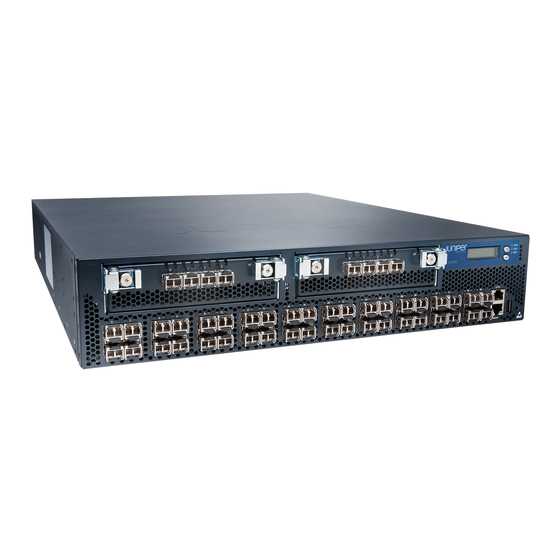
Page 26: Ex4500 Switches
The EX4500 switch is 2 rack units (2 U) in size. Each EX4500 switch is designed to optimize rack space utilization and cabling. See... -
Page 27: Intraconnect Module And Virtual Chassis Module
The Virtual Chassis module has two dedicated Virtual Chassis ports (VCPs) that can be used to interconnect the EX4500 switch with EX4200 switches or EX4500 switches to form a Virtual Chassis. The Virtual Chassis module must be installed in an EX4500 switch to form a Virtual Chassis. -
Page 28: Uplink Modules
SFP+network ports configured as VCPs to form a Virtual Chassis. The number of EX4200 and EX4500 switches that can be interconnected into a mixed Virtual Chassis depends on the Junos OS release running on the switches. See “Understanding... -
Page 29: Ex4500 Switch Models
The EX4500 switch is available in eight models. Table 1 on page 7 lists the models for an EX4500 switch, the airflow direction of the switch, the components included in each model, and the Junos OS Release in which they were introduced. NOTE: The side of the switch where the network ports are located is the front of the switch. - Page 30 Complete Hardware Guide for EX4500 Ethernet Switches Table 1: EX4500 Switch Models, Components, and Supported Junos OS Release (continued) Access Port Direction of Model Configuration Airflow Switch Components First Junos OS Release EX4500-40F-BF-C 40-port Back-to-front Chassis 10.3R1 (CEE capable) GbE/10GbE...
-
Page 31: Identifying Ex4500 Switch Models
Chapter 1: EX4500 Switch Overview Table 1: EX4500 Switch Models, Components, and Supported Junos OS Release (continued) Access Port Direction of Model Configuration Airflow Switch Components First Junos OS Release EX4500-40F-VC1-DC 40-port Front-to-back Chassis 11.1R1 GbE/10GbE One fan tray (with green exhaust... - Page 32 The VC in the model number indicates that the switch model can be used in a Virtual Chassis configuration. NOTE: All EX4500 switch models can be used in a Virtual Chassis configuration if you have installed the Virtual Chassis module. NOTE:...
-
Page 33: Chassis Physical Specifications For Ex4500 Switches
AC power supply: 3 lb (1.3 kg) DC power supply: 3 lb (1.3 kg) You can mount an EX4500 switch on a standard 19-in. two-post rack. You can also mount an EX4500 switch on a standard 19-in. four-post rack or in a standard 19-in. -
Page 34: Figure 4: Ex4500 Switch Front Panel
Complete Hardware Guide for EX4500 Ethernet Switches USB port ESD point Figure 4 on page 12 shows the front panel of an EX4500 switch. Figure 4: EX4500 Switch Front Panel Menu Chassis panel button status LEDs Enter button Console port... -
Page 35: Rear Panel Of An Ex4500 Switch
LCD Panel in EX4500 Switches on page 17 Chassis Status LEDs in EX4500 Switches on page 22 Network Port and Uplink Module Port LEDs in EX4500 Switches on page 24 Uplink Modules in EX4500 Switches on page 36 Optical Interface Support in EX4500 Switches on page 48... -
Page 36: Figure 6: Ex4500 Switch Rear Panel With An Intraconnect Module Installed
“Connecting Earth Ground to an EX Series Switch” on page 125. Figure 6 on page 14 shows the rear panel of an EX4500 switch with AC power supplies and Intraconnect module installed. Figure 6: EX4500 Switch Rear Panel with an Intraconnect Module Installed... -
Page 37: Ex4500 Switch Hardware And Cli Terminology Mapping
Installing and Removing EX4500 Switch Hardware Components on page 109 EX4500 Switch Hardware and CLI Terminology Mapping This topic describes the hardware terms used in EX4500 switch documentation and the corresponding terms used in the Junos OS command line interface (CLI). See... -
Page 38: Ex4500 Switches Hardware Overview
Complete Hardware Guide for EX4500 Ethernet Switches Table 3: CLI Equivalents of Terms Used in Documentation for EX4500 Switches (continued) Hardware Description Item (CLI) (CLI) Value (CLI) Item In Documentation Additional Information Xcvr (n) Abbreviated n is a value equivalent to the Optical transceivers “Optical Interface Support in... -
Page 39: Component Descriptions
Virtual Chassis Module in EX4500 Switches on page 39 LCD Panel in EX4500 Switches The LCD panel on the front panel of EX4500 switch shows two lines of text, each that can contain a maximum of 16 characters. The LCD panel displays a variety of information about the switch and also provides a menu to perform basic operations such as initial setup and reboot. -
Page 40: Lcd Panel Modes
For a standalone EX4500 switch, the slot number is always 00, and the role is always RE. In an EX4500 switch that is a member of a Virtual Chassis, the first line of the LCD panel displays: The slot number (the member ID for the Virtual Chassis member) -
Page 41: Lcd Panel Menus
System halt System reboot Load rescue Request VC port (supported only on EX4500 switches in a Virtual Chassis configuration running Junos OS Release 11.1 or later. This option is not supported on standalone EX4500 switches.) Factory default... - Page 42 Press the Enter button to display the Virtual Chassis port (VCP) status: Up, Down. NOTE: This option is supported only on EX4500 switches in a Virtual Chassis configuration running Junos OS Release 11.1 or later. This option is not supported on standalone EX4500 switches.
- Page 43 (when you delete the VCP, the port is reset to an uplink module port or network port). NOTE: This option is supported only on EX4500 switches in a Virtual Chassis configuration running Junos OS Release 11.1 or later. This option is not supported on standalone EX4500 switches.
-
Page 44: Chassis Status Leds In Ex4500 Switches
Connecting and Configuring an EX Series Switch (J-Web Procedure) on page 155 Chassis Status LEDs in EX4500 Switches The front panel of an EX4500 switch has three chassis status LEDs (labeled ALM, SYS, and MST) on the far right side of the panel, next to the... -
Page 45: Field-Replaceable Units In Ex4500 Switches
A minor alarm that is left unchecked might cause interruption in service or performance degradation. All three LEDs can be lit simultaneously. Related Front Panel of an EX4500 Switch on page 11 Documentation Checking Active Alarms with the J-Web Interface Understanding Alarm Types and Severity Levels on EX Series Switches Field-Replaceable Units in EX4500 Switches Field-replaceable units (FRUs) are components that you can replace at your site. -
Page 46: Network Port And Uplink Module Port Leds In Ex4500 Switches
Figure 10 on page 24 shows the location of the LEDs on the network ports on the front panel of an EX4500 switch. The LEDs point toward the port to which the LEDs belong. Figure 11 on page 25 shows the location of the LEDs on the uplink module ports on the SFP+ uplink module. -
Page 47: Figure 11: Uplink Module Port Leds
Figure 10 on page 24 Figure 11 on page 25 indicate link activity. Table 6 on page 25 describes the Link/Activity LED. Table 6: Link/Activity LED on Network Ports and Uplink Module Ports in EX4500 Switches Color State and Description Link/Activity Green Blinking—The port and the link are active, and there is link... -
Page 48: Management Port Leds In Ex4500 Switches
Documentation Uplink Modules in EX4500 Switches on page 36 Management Port LEDs in EX4500 Switches The management port on the front panel of an EX4500 switch has two LEDs that indicate link/activity and port status (see Figure 12 on page 26). -
Page 49: Ac Power Supply In Ex4500 Switches
The AC power supply in EX4500 switches is a hot-insertable and hot-removable field-replaceable unit (FRU). EX4500 switches are shipped with one power supply. A cover panel is installed in the second power supply slot. You can add a second power supply to the switch. -
Page 50: Figure 13: Ac Power Supply
AC appliance inlet. For instructions for installing the power supply, see “Installing an AC Power Supply in an EX4500 Switch” on page 110. Each AC power supply comes with a power cord retainer that holds the power cord in place. -
Page 51: Ac Power Supply Leds In Ex4500 Switches
The output for the AC power supply is 12 VDC. The output power is 1000 W. Related Installing an AC Power Supply in an EX4500 Switch on page 110 Documentation AC Power Specifications for EX4500 Switches on page 87... -
Page 52: Dc Power Supply In Ex4500 Switches
The DC power supply in EX4500 switches is a hot-insertable and hot-removable field-replaceable unit (FRU). EX4500 switches are shipped with one power supply. A cover panel is installed in the second power supply slot. You can add a second power supply to the switch. -
Page 53: Figure 16: Dc Power Supply
For instructions for installing the power supply, see “Installing a DC Power Supply in an EX4500 Switch” on page 112. Each power supply has its own fan and is cooled by its own internal cooling system. The airflow for a power supply is from the front of the power supply to the back. -
Page 54: Dc Power Supply Leds In Ex4500 Switches
Complete Hardware Guide for EX4500 Ethernet Switches Related Installing a DC Power Supply in an EX4500 Switch on page 112 Documentation DC Power Specifications for EX4500 Switches on page 87 DC Power Supply LEDs in EX4500 Switches on page 32 DC Power Supply LEDs in EX4500 Switches A DC power supply has one bicolor LED (labeled POK) on its faceplate. -
Page 55: Cooling System And Airflow In An Ex4500 Switch
Chapter 2: Component Descriptions Cooling System and Airflow in an EX4500 Switch The cooling system in an EX4500 switch consists of a single fan tray. The fan tray is a hot-insertable and hot-removable field-replaceable unit (FRU). The fan tray contains... -
Page 56: Figure 19: Front-To-Back Airflow Through The Ex4500 Switch Chassis
EX4500-40F-VC1-DC Front-to-back In the EX4500 switch models that have front-to-back airflow, the air intake to cool the chassis is located on the front of the chassis. Air is pulled into the chassis and pushed toward the fan tray. Hot air exhausts from the rear of the chassis. See... -
Page 57: Figure 20: Back-To-Front Airflow Through The Ex4500 Switch Chassis
Chapter 2: Component Descriptions Figure 20: Back-to-Front Airflow Through the EX4500 Switch Chassis Front Fans (5) Rear Each fan tray has colored intake or exhaust labels that are visible through the fan tray vents. The label is orange. The label is green. -
Page 58: Uplink Modules In Ex4500 Switches
You must order them separately. You can install up to two SFP+ uplink modules in an EX4500 switch. Both uplink modules install horizontally on the front of the chassis. The uplink module slot on the left is PIC 1. -
Page 59: Figure 22: Sfp+ Uplink Module
Each uplink module port has a pair of LEDs that indicate the link/activity and status of the port. See “Network Port and Uplink Module Port LEDs in EX4500 Switches” on page 24 for details about the uplink module port LEDs. -
Page 60: Intraconnect Module In Ex4500 Switches
Complete Hardware Guide for EX4500 Ethernet Switches Intraconnect Module in EX4500 Switches The intraconnect module is installed horizontally on the rear of an EX4500 switch chassis. The intraconnect module helps the switch achieve line rate on all its ports. The module is an offline field-replaceable unit (FRU). -
Page 61: Virtual Chassis Module In Ex4500 Switches
Installing an Intraconnect Module in an EX4500 Switch on page 117 Virtual Chassis Module in EX4500 Switches The Virtual Chassis module is installed horizontally on the rear panel of an EX4500 switch chassis. The Virtual Chassis module has two dedicated Virtual Chassis ports (VCPs) that can be used to interconnect the EX4500 switch with an EX4200 switch or an EX4500 switch in a Virtual Chassis configuration. -
Page 62: Figure 25: Virtual Chassis Module Leds
“Removing a Virtual Chassis Module from an EX4500 Switch” on page 173. Related Rear Panel of an EX4500 Switch on page 13 Documentation Field-Replaceable Units in EX4500 Switches on page 23 Installing a Virtual Chassis Module in an EX4500 Switch on page 119 Copyright © 2011, Juniper Networks, Inc. -
Page 63: Component Specifications
USB Port Specifications for an EX Series Switch on page 41 Console Port Connector Pinout Information for an EX Series Switch on page 42 Management Port Connector Pinout Information for an EX4500 Switch on page 43 Network Port and Uplink Module Port Connector Pinout Information for EX4500... -
Page 64: Console Port Connector Pinout Information For An Ex Series Switch
See Rear Panel of an EX3300 Switch for port location. See Rear Panel of an EX4200 Switch for port location. Front Panel of an EX4500 Switch on page 11 for port location. See Switch Fabric and Routing Engine (SRE) Module in an EX6200 Switch for port location. -
Page 65: Management Port Connector Pinout Information For An Ex4500 Switch
Configuring the Console Port Type (CLI Procedure) Management Port Connector Pinout Information for an EX4500 Switch The management port on an EX4500 switch uses an RJ-45 connector to connect to a management device for out-of-band management. The port uses an autosensing RJ-45 connector to support a 10/100/1000Base-T connection. -
Page 66: Switches
Network Port and Uplink Module Port Connector Pinout Information for EX4500 Switches The network ports and uplink module ports on an EX4500 switch have two LEDs on each port that indicate link/activity on the port and the port status. See “Network Port and... -
Page 67: Virtual Chassis Ports Connector Pinout Information For Ex4500 Switches
Documentation Uplink Modules in EX4500 Switches on page 36 Virtual Chassis Ports Connector Pinout Information for EX4500 Switches EX4500 switches use a 68-pin connector cable to interconnect switches to form a Virtual Chassis. Table 19 on page 45 provides the Virtual Chassis ports (VCPs) connector pinout information. - Page 68 Complete Hardware Guide for EX4500 Ethernet Switches Table 19: Virtual Chassis Ports (VCPs) Connector Pinout Information (continued) Pin Number Pin Name P1TXN1 P1TXP2 P1TXN2 P1TXP3 P1TXN3 P2TXP0 P2TXN0 P2TXP1 P2TXN1 P2TXP2 Copyright © 2011, Juniper Networks, Inc.
- Page 69 Chapter 3: Component Specifications Table 19: Virtual Chassis Ports (VCPs) Connector Pinout Information (continued) Pin Number Pin Name P2TXN2 P2TXP3 P2TXN3 P1RXP0 P1RXN0 P1RXP1 P1RXN1 P1RXP2 P1RXN2 P1RXP3 P1RXN3 Copyright © 2011, Juniper Networks, Inc.
-
Page 70: Optical Interface Support In Ex4500 Switches
Connecting a Virtual Chassis Cable to an EX4500 Switch on page 121 Optical Interface Support in EX4500 Switches Uplink module ports on EX4500 switches support SFP and SFP+ transceivers. This topic describes the optical interfaces supported for those transceivers. It also lists the copper interface supported for the SFP transceivers. -
Page 71: Table 20: Optical Interface Support And Copper Interface Support For Gigabit Ethernet Sfp Transceivers In Ex4500 Switches
Use only optical transceivers and optical connectors purchased from Juniper Networks for your EX Series switches. The Gigabit Ethernet SFP and SFP+ transceivers installed in EX4500 switches support digital optical monitoring (DOM): You can view the diagnostic details for these transceivers... - Page 72 Complete Hardware Guide for EX4500 Ethernet Switches Table 20: Optical Interface Support and Copper Interface Support for Gigabit Ethernet SFP Transceivers in EX4500 Switches (continued) Ethernet Standard Specification Value 1000BASE-SX Model Number EX-SFP-1GE-SX Rate 1000 Mbps Connector Type Transmitter Wavelength...
- Page 73 Chapter 3: Component Specifications Table 20: Optical Interface Support and Copper Interface Support for Gigabit Ethernet SFP Transceivers in EX4500 Switches (continued) Ethernet Standard Specification Value 1000BASE-LX Model Number EX-SFP-1GE-LX Rate 1000 Mbps Connector Type Fiber Count Dual Transmitter Wavelength...
- Page 74 Complete Hardware Guide for EX4500 Ethernet Switches Table 20: Optical Interface Support and Copper Interface Support for Gigabit Ethernet SFP Transceivers in EX4500 Switches (continued) Ethernet Standard Specification Value 1000BASE-BX-U Model Number EX-SFP-GE10KT13R14 Rate 1000 Mbps Connector Type Fiber Count...
- Page 75 Chapter 3: Component Specifications Table 20: Optical Interface Support and Copper Interface Support for Gigabit Ethernet SFP Transceivers in EX4500 Switches (continued) Ethernet Standard Specification Value 1000BASE-BX-D Model Number EX-SFP-GE10KT14R13 Rate 1000 Mbps Connector Type Fiber Count Single Transmitter Wavelength...
- Page 76 Complete Hardware Guide for EX4500 Ethernet Switches Table 20: Optical Interface Support and Copper Interface Support for Gigabit Ethernet SFP Transceivers in EX4500 Switches (continued) Ethernet Standard Specification Value 1000BASE-BX-U Model Number EX-SFP-GE10KT13R15 Rate 1000 Mbps Connector Type Fiber Count...
- Page 77 Chapter 3: Component Specifications Table 20: Optical Interface Support and Copper Interface Support for Gigabit Ethernet SFP Transceivers in EX4500 Switches (continued) Ethernet Standard Specification Value 1000BASE-BX-D Model Number EX-SFP-GE10KT15R13 Rate 1000 Mbps Connector Type Fiber Count Single Transmitter Wavelength...
- Page 78 Complete Hardware Guide for EX4500 Ethernet Switches Table 20: Optical Interface Support and Copper Interface Support for Gigabit Ethernet SFP Transceivers in EX4500 Switches (continued) Ethernet Standard Specification Value 1000BASE-BX-U Model Number EX-SFP-GE40KT13R15 Rate 1000 Mbps Connector Type Fiber Count...
- Page 79 Chapter 3: Component Specifications Table 20: Optical Interface Support and Copper Interface Support for Gigabit Ethernet SFP Transceivers in EX4500 Switches (continued) Ethernet Standard Specification Value 1000BASE-BX-D Model Number EX-SFP-GE40KT15R13 Rate 1000 Mbps Connector Type Fiber Count Single Transmitter Wavelength...
- Page 80 Complete Hardware Guide for EX4500 Ethernet Switches Table 20: Optical Interface Support and Copper Interface Support for Gigabit Ethernet SFP Transceivers in EX4500 Switches (continued) Ethernet Standard Specification Value 1000BASE-LX Model Number EX-SFP-1GE-LX40K Rate 1000 Mbps Connector Type Fiber Count...
- Page 81 Chapter 3: Component Specifications Table 20: Optical Interface Support and Copper Interface Support for Gigabit Ethernet SFP Transceivers in EX4500 Switches (continued) Ethernet Standard Specification Value 1000BASE-LH (or Model Number EX-SFP-1GE-LH 1000BASE-ZX) Rate 1000 Mbps Connector Type Fiber Count Dual...
-
Page 82: Table 21: Optical Interface Support For Gigabit Ethernet Sfp+ Transceivers In
Complete Hardware Guide for EX4500 Ethernet Switches Table 21: Optical Interface Support for Gigabit Ethernet SFP+ Transceivers in EX4500 Switches Ethernet Standard Specification Value 10GBASE-SR Model Number EX-SFP-10GE-USR Rate 10 Gbps Connector Type Fiber Count Dual Transmitter Wavelength 850 nm Minimum Launch Power –7.3 dBm... - Page 83 Chapter 3: Component Specifications Table 21: Optical Interface Support for Gigabit Ethernet SFP+ Transceivers in EX4500 Switches (continued) Ethernet Standard Specification Value 10GBASE-SR Model Number EX-SFP-10GE-SR Rate 10 Gbps Connector Type Fiber Count Dual Transmitter Wavelength 850 nm Minimum Launch Power –7.3 dBm...
- Page 84 Complete Hardware Guide for EX4500 Ethernet Switches Table 21: Optical Interface Support for Gigabit Ethernet SFP+ Transceivers in EX4500 Switches (continued) Ethernet Standard Specification Value 10GBASE-LRM Model Number EX-SFP-10GE-LRM Rate 10 Gbps Connector Type Fiber Count Dual Transmitter Wavelength 1310 nm Minimum Launch Power –6.5 dBm...
- Page 85 Chapter 3: Component Specifications Table 21: Optical Interface Support for Gigabit Ethernet SFP+ Transceivers in EX4500 Switches (continued) Ethernet Standard Specification Value 10GBASE-LR Model Number EX-SFP-10GE-LR Rate 10 Gbps Connector Type Fiber Count Dual Transmitter Wavelength 1310 nm Minimum Launch Power –8.2 dBm...
-
Page 86: Sfp+ Direct Attach Cables For Ex Series Switches
Complete Hardware Guide for EX4500 Ethernet Switches Table 21: Optical Interface Support for Gigabit Ethernet SFP+ Transceivers in EX4500 Switches (continued) Ethernet Standard Specification Value 10GBASE-ER Model Number EX-SFP-10GE-ER Rate 10 Gbps Connector Type Fiber Count Dual Transmitter Wavelength 1550 nm Minimum Launch Power –4.7 dBm... -
Page 87: Cable Specifications
Cable Specifications on page 65 Standards Supported by These Cables on page 68 Cable Specifications Juniper Networks SFP+ direct attach cables are available in four length—1 m, 3 m, 5 m, and 7 m. Table 22 on page 65 describes the software support for SFP+ direct attach cable length... -
Page 88: Table 23: Sfp+ Direct Attach Cable Specifications
Complete Hardware Guide for EX4500 Ethernet Switches Table 23: SFP+ Direct Attach Cable Specifications Model Specification Value EX-SFP-10GE-DAC-1m Rate 10 Gbps full-duplex serial transmission Connector type SFP+ passive Twinax cable assembly Supply voltage 3.3 V Power consumption (per end) 0.57 W °... - Page 89 C through 85 Cable type Twinax Wire AWG 24 AWG Minimum cable bend radius 1 in. Cable characteristic impedance 100 ohms Crosstalk between pairs 2% maximum Time delay 1.31 nsec/ft Length 23 ft (7 m) Copyright © 2011, Juniper Networks, Inc.
-
Page 90: Standards Supported By These Cables
The grounding points fit UNC 10-32 screws. The grounding points are spaced at 0.625 in. (15.86 mm). The grounding cable that you provide for an EX4500 switch must be 14 AWG (2 mm minimum 90°C wire, or as permitted by the local code. - Page 91 Related AC Power Supply in EX4500 Switches on page 27 Documentation Installing an AC Power Supply in an EX4500 Switch on page 110 Copyright © 2011, Juniper Networks, Inc.
- Page 92 Complete Hardware Guide for EX4500 Ethernet Switches Copyright © 2011, Juniper Networks, Inc.
-
Page 93: Planning For Switch Installation
Planning for Switch Installation Site Preparation on page 73 Rack and Cabinet Requirements on page 79 Cable Requirements on page 85 Planning Power Requirements on page 87 Planning the Virtual Chassis on page 91 Copyright © 2011, Juniper Networks, Inc. - Page 94 Complete Hardware Guide for EX4500 Ethernet Switches Copyright © 2011, Juniper Networks, Inc.
-
Page 95: Site Preparation
CHAPTER 4 Site Preparation Site Preparation Checklist for EX4500 Switches on page 73 General Site Guidelines on page 74 Site Electrical Wiring Guidelines on page 75 Environmental Requirements and Specifications for EX Series Switches on page 76 Site Preparation Checklist for EX4500 Switches... -
Page 96: General Site Guidelines
General Safety Guidelines and Warnings on page 203 Documentation General Site Guidelines on page 74 Installing and Connecting an EX4500 Switch on page 99 Mounting an EX4500 Switch on page 102 General Site Guidelines This topic applies to hardware devices in the EX Series product family, which includes switches and the XRE200 External Routing Engine. -
Page 97: Site Electrical Wiring Guidelines
Improperly installed wires cause radio frequency interference (RFI). Damage from lightning strikes occurs when wires exceed recommended distances or pass between buildings. Electromagnetic pulses (EMPs) caused by lightning damages unshielded conductors and electronic devices. Copyright © 2011, Juniper Networks, Inc. -
Page 98: Environmental Requirements And Specifications For Ex Series Switches
Power Supply in EX3200 Switches Power Supply in EX3300 Switches Power Supply in EX4200 Switches AC Power Supply in EX4500 Switches on page 27 DC Power Supply in EX4500 Switches on page 30 AC Power Supply in an EX6200 Switch... -
Page 99: Table 26: Ex Series Switch Environmental Tolerances
85%, noncondensing Temperature EX2200 (except EX2200-C models), EX3200, EX3300, EX4200, and EX4500 switches: Normal operation ensured in temperature range of 32° F through 113° F (0° C through 45° C) EX2200-C switches: At temperature range of 32° F through 104° F (0° C through 40°... - Page 100 Complete Hardware Guide for EX4500 Ethernet Switches Clearance Requirements for Airflow and Hardware Maintenance for EX4500 Switches on page 81 Clearance Requirements for Airflow and Hardware Maintenance for an EX6210 Switch Clearance Requirements for Airflow and Hardware Maintenance for an EX8208 Switch Clearance Requirements for Airflow and Hardware Maintenance for an EX8216 Switch Copyright ©...
-
Page 101: Rack And Cabinet Requirements
Rack and Cabinet Requirements Rack Requirements for EX4500 Switches on page 79 Cabinet Requirements for EX4500 Switches on page 80 Clearance Requirements for Airflow and Hardware Maintenance for EX4500 Switches on page 81 Rack Requirements for EX4500 Switches You can mount the switch on two-post racks or four-post racks. -
Page 102: Cabinet Requirements For Ex4500 Switches
Related Chassis Physical Specifications for EX4500 Switches on page 11 Documentation Clearance Requirements for Airflow and Hardware Maintenance for EX4500 Switches on page 81 Rack-Mounting and Cabinet-Mounting Warnings on page 216 Mounting an EX4500 Switch on page 102 Cabinet Requirements for EX4500 Switches You can mount the switch in a cabinet that contains a 19-in. -
Page 103: Switches
Rack-Mounting and Cabinet-Mounting Warnings on page 216 Mounting an EX4500 Switch on page 102 Clearance Requirements for Airflow and Hardware Maintenance for EX4500 Switches When planning the site for installing an EX4500 switch, you must allow sufficient clearance around the switch. Follow these clearance requirements:... -
Page 104: Figure 26: Front-To-Back Airflow Through The Ex4500-40F-Fb Switch
Allow at least 6 in. (15.2 cm) of clearance on each side of the chassis. For the cooling system to function properly, the airflow around the chassis must be unrestricted. See Figure 26 on page 82 Figure 27 on page Figure 26: Front-to-Back Airflow Through the EX4500-40F-FB Switch Chassis Front Fans (5) -
Page 105: Figure 28: Clearance Requirements For Airflow And Hardware Maintenance For
Rack Requirements for EX4500 Switches on page 79 Documentation Cabinet Requirements for EX4500 Switches on page 80 General Site Guidelines on page 74 Rack-Mounting and Cabinet-Mounting Warnings on page 216 Cooling System and Airflow in an EX4500 Switch on page 33 Copyright © 2011, Juniper Networks, Inc. - Page 106 Complete Hardware Guide for EX4500 Ethernet Switches Copyright © 2011, Juniper Networks, Inc.
-
Page 107: Cable Requirements
Planning EX4200 and EX4500 Virtual Chassis on page 93 Documentation Virtual Chassis Ports Connector Pinout Information for EX4500 Switches on page 45 Management Port Connector Pinout Information for an EX4500 Switch on page 43 Console Port Connector Pinout Information for an EX Series Switch on page 42 Front Panel of an EX4500 Switch on page 11 Copyright ©... - Page 108 Complete Hardware Guide for EX4500 Ethernet Switches Copyright © 2011, Juniper Networks, Inc.
-
Page 109: Planning Power Requirements
AC Power Specifications for EX4500 Switches Table 29 on page 87 lists the AC power specifications for a 1000 W power supply used in EX4500 switches. Table 29: Power Specifications for an AC Power Supply Used in EX4500 Switches Item Specifications AC input voltage Operating range—100–240 VAC... -
Page 110: Ac Power Cord Specifications For An Ex4500 Switch
DC Power Supply LEDs in EX4500 Switches on page 32 AC Power Cord Specifications for an EX4500 Switch Each AC power supply for the EX4500 switch has a single AC appliance inlet located on the power supply that requires a dedicated AC power feed. Most sites distribute power through a main conduit that leads to frame-mounted power distribution panels, one of which can be located at the top of the rack that houses the switch. -
Page 111: Figure 29: Ac Plug Types
Chapter 7: Planning Power Requirements Table 31: AC Power Cord Specifications for an EX4500 Switch (continued) Country/Region Electrical Specifications Plug Standards Europe (except Italy, 250 VAC, 16 A, 50 Hz CEE (7) VII Switzerland, and United Kingdom) Italy 250 VAC, 16 A, 50 Hz... - Page 112 Complete Hardware Guide for EX4500 Ethernet Switches CAUTION: The AC power cord for the EX4500 switch is intended for use with this switch only and not for any other use. Power Cable Warning (Japanese) WARNING: The attached power cable is only for this product. Do not use the cable for another product.
-
Page 113: Planning The Virtual Chassis
You can interconnect EX4200 switches together to form a Virtual Chassis composed exclusively of EX4200 switches. You can interconnect EX4500 switches together to form a Virtual Chassis composed exclusively of EX4500 switches. You can also interconnect EX4200 switches with EX4500 switches to form a mixed EX4200 and EX4500 Virtual Chassis. -
Page 114: Number Of Switches, Required Software Releases, And Member Roles That You Configure In The Virtual Chassis
Number of Switches Role 9.4 or later Up to 10 EX4200 switches 1 master, 1 backup, remainder linecard Table 33: Number of Switches and Switch Roles for an EX4500 Virtual Chassis, per Junos OS Release Junos OS Release Number of Switches Role 11.1—11.3... -
Page 115: Virtual Chassis Module-A Required Component For Virtual Chassis That Include Ex4500 Switches
Virtual Chassis Module—a Required Component for Virtual Chassis That Include EX4500 Switches The Virtual Chassis module must be installed in an EX4500 switch for that switch to be part of a Virtual Chassis. Switch Role and Member ID on the LCD Panel For each switch in the Virtual Chassis, the switch’s LCD panel displays:... -
Page 116: Table 36: Cabling Requirements For A Virtual Chassis
EX4200 and EX4500 switches can be connected together into the same Virtual Chassis to form a mixed EX4200 and EX4500 Virtual Chassis. You can interconnect EX4200 and EX4500 switches through the dedicated Virtual Chassis ports (VCPs) to form a mixed Virtual Chassis. - Page 117 Understanding EX4200 and EX4500 Virtual Chassis Hardware Configurations on page 91 Virtual Chassis Cabling Configuration Examples for EX4200 Switches Clearance Requirements for Airflow and Hardware Maintenance for EX4200 Switches Clearance Requirements for Airflow and Hardware Maintenance for EX4500 Switches on page 81 Copyright © 2011, Juniper Networks, Inc.
- Page 118 Complete Hardware Guide for EX4500 Ethernet Switches Copyright © 2011, Juniper Networks, Inc.
- Page 119 PART 3 Installing and Connecting the Switch and Switch Components Installing the Switch on page 99 Installing Switch Components on page 109 Connecting the Switch on page 125 Performing Initial Configuration on page 147 Copyright © 2011, Juniper Networks, Inc.
- Page 120 Complete Hardware Guide for EX4500 Ethernet Switches Copyright © 2011, Juniper Networks, Inc.
-
Page 121: Installing The Switch
Mounting an EX4500 Switch on Two Posts in a Rack or Cabinet on page 102 Mounting an EX4500 Switch on Four Posts in a Rack or Cabinet on page 104 Mounting an EX4500 Switch in a Recessed Position in a Rack or Cabinet on page 107 Installing and Connecting an EX4500 Switch... -
Page 122: Unpacking An Ex4500 Switch
Clearance Requirements for Airflow and Hardware Maintenance for EX4500 Switches on page 81 Unpacking an EX4500 Switch The EX4500 switches are shipped in a cardboard carton, secured with foam packing material. The carton has an accessory compartment and contains the quick start instructions. -
Page 123: Table 37: Inventory Of Components Provided With An Ex4500 Switch
Chapter 9: Installing the Switch Table 37: Inventory of Components Provided with an EX4500 Switch Component Quantity Switch Intraconnect module or Virtual Chassis module (preinstalled) Fan tray (preinstalled) Power supply (preinstalled) 1 AC or DC AC power cord appropriate for your geographical location (only for AC switch models) -
Page 124: Mounting An Ex4500 Switch
Mounting an EX4500 Switch on Two Posts in a Rack or Cabinet You can mount an EX4500 switch on two posts of a 19-in. rack or cabinet by using the mounting brackets provided with the switch. (The remainder of this topic uses “rack” to mean “rack or cabinet.”) -
Page 125: Figure 30: Attaching The Mounting Bracket Along The Front Of The Switch
Insert a screw in each hole and tighten the screws. Have one person grasp both sides of the switch, lift the switch, and position it in the rack, aligning the mounting bracket holes with the threaded holes in the rack or cabinet Copyright © 2011, Juniper Networks, Inc. -
Page 126: Mounting An Ex4500 Switch On Four Posts In A Rack Or Cabinet
Mounting an EX4500 Switch on Four Posts in a Rack or Cabinet You can mount an EX4500 switch on four posts of a 19-in. rack or cabinet by using the separately orderable four-post rack-mount kit. (The remainder of this topic uses “rack”... - Page 127 Read “General Safety Guidelines and Warnings” on page 203, with particular attention “Chassis Lifting Guidelines for EX4500 Switches” on page 214. Remove the switch from the shipping carton (see “Unpacking an EX4500 Switch” on page 100).
-
Page 128: Figure 32: Attaching The Front Bracket To The Switch Chassis
Complete Hardware Guide for EX4500 Ethernet Switches NOTE: Each side of the chassis has twelve holes for attaching the front brackets to the switch. Six holes on the chassis side align with six holes in the front bracket when the front bracket is mounted flush with the chassis front or recessed 2 in. -
Page 129: Mounting An Ex4500 Switch In A Recessed Position In A Rack Or Cabinet
Mounting an EX4500 Switch in a Recessed Position in a Rack or Cabinet You can mount an EX4500 switch in a rack or cabinet such that the switch is recessed inside the rack from the rack front by 2 inches. Use the front brackets provided in the separately orderable four-post rack-mount kit to mount the switch in a recessed position. - Page 130 Complete Hardware Guide for EX4500 Ethernet Switches Related Connecting Earth Ground to an EX Series Switch on page 125 Documentation Rack-Mounting and Cabinet-Mounting Warnings on page 216 Copyright © 2011, Juniper Networks, Inc.
-
Page 131: Installing Switch Components
Installing a Transceiver in an EX Series Switch on page 122 Installing and Removing EX4500 Switch Hardware Components The EX4500 switch chassis is a rigid sheet-metal structure that houses the hardware components. The field-replaceable units (FRUs) in EX4500 switches are:... -
Page 132: Installing An Ac Power Supply In An Ex4500 Switch
Complete Hardware Guide for EX4500 Ethernet Switches Installing an AC Power Supply in an EX4500 Switch on page 110 Removing an AC Power Supply from an EX4500 Switch on page 164 Installing a DC Power Supply in an EX4500 Switch on page 112... -
Page 133: Figure 35: Installing A Power Supply In An Ex4500 Switch
It does not apply if you replace these components with the same type of component. Related Removing an AC Power Supply from an EX4500 Switch on page 164 Documentation AC Power Supply in EX4500 Switches on page 27... -
Page 134: Installing A Dc Power Supply In An Ex4500 Switch
Rear Panel of an EX4500 Switch on page 13 Installing a DC Power Supply in an EX4500 Switch The DC power supply in EX4500 switches is a hot-removable and hot-insertable field-replaceable unit (FRU): You can remove and replace it without powering off the switch or disrupting switch functions. -
Page 135: Installing A Fan Tray In An Ex4500 Switch
Rear Panel of an EX4500 Switch on page 13 Installing a Fan Tray in an EX4500 Switch An EX4500 switch has a single fan tray. The fan tray is a hot-insertable and hot-removable field-replaceable unit (FRU); you can remove and replace the fan tray while the switch is running without turning off power to the switch or disrupting switching functions. -
Page 136: Figure 37: Installing A Fan Tray In An Ex4500 Switch
Figure 37: Installing a Fan Tray in an EX4500 Switch Fan tray Fan tray handle Related Removing a Fan Tray from an EX4500 Switch on page 168 Documentation Cooling System and Airflow in an EX4500 Switch on page 33 Field-Replaceable Units in EX4500 Switches on page 23... -
Page 137: Installing An Uplink Module In An Ex4500 Switch
(FRU): You can remove and replace it without powering off the switch or disrupting switch functions. You can install up to two SFP+ uplink modules in an EX4500 switch. Both uplink modules install horizontally on the front of the chassis. The uplink module slot on the left is PIC 1. -
Page 138: Figure 39: Installing An Uplink Module In An Ex4500 Switch
Complete Hardware Guide for EX4500 Ethernet Switches To install an uplink module in an EX4500 switch (see Figure 39 on page 116): Attach the electrostatic discharge (ESD) grounding strap to your bare wrist, and connect the strap to the ESD point on the chassis. -
Page 139: Installing An Intraconnect Module In An Ex4500 Switch
Operating an EX4500 switch without the intraconnect module or the Virtual Chassis module is not supported. EX4500 switches running Junos OS Release 10.4R2 or later 10.4 releases will not boot if you do not install the intraconnect module in the switch. - Page 140 Complete Hardware Guide for EX4500 Ethernet Switches NOTE: You must remove the fan tray from the EX4500 switch before installing the intraconnect module. See “Removing a Fan Tray from an EX4500 Switch” on page 168. To install an intraconnect module in the switch (see...
-
Page 141: Installing A Virtual Chassis Module In An Ex4500 Switch
Operating an EX4500 switch without the intraconnect module or the Virtual Chassis module is not supported. EX4500 switches running Junos OS Release 10.4R2 or later 10.4 releases will not boot if you do not install the intraconnect module in the switch. - Page 142 Virtual Chassis module. After you install the module, you must install the fan tray. See “Removing a Fan Tray from an EX4500 Switch” on page 168 “Installing a Fan Tray in an EX4500 Switch”...
-
Page 143: Connecting A Virtual Chassis Cable To An Ex4500 Switch
The Virtual Chassis module has two dedicated Virtual Chassis ports (VCPs) that can be used to interconnect the EX4500 switch with EX4200 switches or EX4500 switches to form a Virtual Chassis. The Virtual Chassis module is installed on the rear side of the switch chassis. -
Page 144: Installing A Transceiver In An Ex Series Switch
Virtual Chassis cables and Virtual Chassis cable connector retainers are not part of the EX4500 switch’s shipping configuration. If you want to purchase these, you must order them separately. To connect a Virtual Chassis cable to a dedicated VCP on an EX4500 switch (see Figure 42 on page... - Page 145 After you insert a transceiver or when you change the media-type configuration, wait for 6 seconds for the interface to display the operational commands. Use only optical transceivers and optical connectors purchased from Juniper Networks for your EX Series switches. NOTE:...
-
Page 146: Figure 43: Installing A Transceiver In An Ex Series Switch
Optical Interface Support in EX3200 Switches Optical Interface Support in EX3300 Switches Optical Interface Support in EX4200 Switches Optical Interface Support in EX4500 Switches on page 48 Optical Interface Support in EX6200 Switches Optical Interface Support in EX8200 Switches Copyright © 2011, Juniper Networks, Inc. -
Page 147: Connecting The Switch
Connecting the Switch Connecting Earth Ground to an EX Series Switch on page 125 Connecting AC Power to an EX4500 Switch on page 131 Connecting DC Power to an EX4500 Switch on page 133 Connecting an EX Series Switch to a Network for Out-of-Band Management on page 137... -
Page 148: Connecting Earth Ground To An Ex2200, Ex3200, Or Ex3300 Switch
Follow the procedure that applies to your switch: Connecting Earth Ground to an EX2200, EX3200, or EX3300 Switch on page 126 Connecting Earth Ground to an EX4500 Switch on page 127 Connecting Earth Ground to an EX6210 Switch on page 128... -
Page 149: Connecting Earth Ground To An Ex4500 Switch
Connecting Earth Ground to an EX4500 Switch The protective earthing terminal is located on the left rear of the chassis in an EX4500 switch. An AC-powered EX Series switch chassis gets additional grounding when you plug the power supply in the switch into a grounded AC power outlet by using an AC power cord appropriate for your geographical location. -
Page 150: Connecting Earth Ground To An Ex6210 Switch
Complete Hardware Guide for EX4500 Ethernet Switches Secure the grounding lug to the protective earthing terminal with screws. Dress the grounding cable and ensure that it does not touch or block access to other switch components and that it does not drape where people could trip over it. -
Page 151: Connecting Earth Ground To An Ex8208 Switch
Connect one end of the grounding cable to a proper earth ground, such as the rack in which the switch is mounted. Place the grounding lug attached to the grounding cable over the protective earthing terminal. See Figure 44 on page 125. Copyright © 2011, Juniper Networks, Inc. -
Page 152: Connecting Earth Ground To An Ex8216 Switch
Complete Hardware Guide for EX4500 Ethernet Switches Secure the grounding lug to the protective earthing terminal with the washers and screws. Dress the grounding cable and ensure that it does not touch or block access to other switch components and that it does not drape where people could trip over it. -
Page 153: Connecting Ac Power To An Ex4500 Switch
Grounded Equipment Warning on page 220 Connecting AC Power to an EX4500 Switch The AC power supply in an EX4500 switch is a hot-removable and hot-insertable field-replaceable unit (FRU). After you have installed at least one power supply, you can connect power to the switch. -
Page 154: Figure 46: Power Cord Retainer In An Ac Power Supply
“Prevention of Electrostatic Discharge Damage” on page 228. Install power supplies in the switch. See “Installing an AC Power Supply in an EX4500 Switch” on page 110. Ensure that you have the following parts and tools available to connect power to the... -
Page 155: Connecting Dc Power To An Ex4500 Switch
AC Power Supply LEDs in EX4500 Switches on page 29 Connecting DC Power to an EX4500 Switch You can install two DC power supplies in an EX4500 switch. After you have installed at least one power supply, you can connect power to the switch. - Page 156 For instructions on connecting an EX4500 switch to ground using a separate grounding conductor, see “Connecting Earth Ground to an EX Series Switch”...
-
Page 157: Figure 48: Remove Plastic Cover From Terminal Block
It might be necessary to slide each power supply partially out of the chassis to easily connect the DC power source cables to the DC power input terminals. See “Removing a DC Power Supply from an EX4500 Switch” on page 166. -
Page 158: Figure 49: Connecting The Power Supply Cables To An Ex4500 Switch
Complete Hardware Guide for EX4500 Ethernet Switches Figure 49: Connecting the Power Supply Cables to an EX4500 Switch Slide the plastic cover over the input terminal block. See Figure 50 on page 136 Figure 50: Install Plastic Cover on Terminal Block Ensure that the power supply is fully inserted and latched securely in the chassis. -
Page 159: Connecting An Ex Series Switch To A Network For Out-Of-Band Management
See Rear Panel of an EX3300 Switch. See Rear Panel of an EX4200 Switch. “Front Panel of an EX4500 Switch” on page See Switch Fabric and Routing Engine (SRE) Module in an EX6200 Switch. See Switch Fabric and Routing Engine (SRE) Module in an EX8208 Switch. -
Page 160: Connecting An Ex Series Switch To A Management Console
Management Port Connector Pinout Information for an EX3300 Switch Management Port Connector Pinout Information for an EX4200 Switch Management Port Connector Pinout Information for an EX4500 Switch on page 43 Management Port Connector Pinout Information for an EX6200 Switch Management Port Connector Pinout Information for an EX8200 Switch... -
Page 161: Console Port
See Rear Panel of an EX3300 Switch. See Rear Panel of an EX4200 Switch. “Front Panel of an EX4500 Switch” on page See Switch Fabric and Routing Engine (SRE) Module in an EX6200 Switch. See Switch Fabric and Routing Engine (SRE) Module in an EX8208 Switch. -
Page 162: Connecting An Ex2200 Switch To A Management Console Using Mini-Usb Type-B Console Port
Complete Hardware Guide for EX4500 Ethernet Switches Connect the other end of the Ethernet cable into the console server (see Figure 54 on page 140) or management console (see Figure 55 on page 140). To configure the device from the management console, see “Connecting and Configuring... -
Page 163: Connecting An Ex Series Switch To A Modem
Setting the Serial Console Speed for the Switch Before you can connect the switch to a modem, the switch’s serial console speed must be set to 115200 baud. NOTE: The default serial console speed is 9600 baud. Copyright © 2011, Juniper Networks, Inc. -
Page 164: Configuring The Modem
Complete Hardware Guide for EX4500 Ethernet Switches To change the serial console speed: Power on the switch. (For EX8208 or EX8216 switch models, see Powering On an EX8200 Switch. For EX6200 switches, see Powering On an EX6200 Switch) The loader script starts. -
Page 165: Connecting The Modem To The Console Port
The console port on every EX Series switch accepts a cable with an RJ-45 connector. Figure 56 on page 143 shows the RJ-45 connector of the Ethernet cable supplied with the switch. Figure 56: Ethernet Cable Connector Copyright © 2011, Juniper Networks, Inc. - Page 166 See Rear Panel of an EX3300 Switch. See Rear Panel of an EX4200 Switch. “Front Panel of an EX4500 Switch” on page See Switch Fabric and Routing Engine (SRE) Module in an EX8208 Switch. See Routing Engine (RE) Module in an EX8216 Switch.
-
Page 167: Connecting A Fiber-Optic Cable To An Ex Series Switch
Do not let fiber-optic cables hang free from the connector. Do not allow fastened loops of cables to dangle, which stresses the cables at the fastening point. Copyright © 2011, Juniper Networks, Inc. - Page 168 Optical Interface Support in EX3200 Switches Optical Interface Support in EX3300 Switches Optical Interface Support in EX4200 Switches Optical Interface Support in EX4500 Switches on page 48 Optical Interface Support in EX6200 Switches Optical Interface Support in EX8200 Switches Copyright © 2011, Juniper Networks, Inc.
-
Page 169: Performing Initial Configuration
You can always revert to the factory default configuration. See Reverting to the Default Factory Configuration for the EX Series Switch. This topic shows the factory default configuration file of an EX4500 switch: system { syslog { user * { any emergency;... - Page 170 Complete Hardware Guide for EX4500 Ethernet Switches commit { factory-settings { reset-chassis-lcd-menu; reset-virtual-chassis-configuration; interfaces { xe-0/0/0 { unit 0 { family ethernet-switching; xe-0/0/1 { unit 0 { family ethernet-switching; xe-0/0/2 { unit 0 { family ethernet-switching; xe-0/0/3 { unit 0 { family ethernet-switching;...
- Page 171 { unit 0 { family ethernet-switching; xe-0/0/17 { unit 0 { family ethernet-switching; xe-0/0/18 { unit 0 { family ethernet-switching; xe-0/0/19 { unit 0 { family ethernet-switching; xe-0/0/20 { unit 0 { family ethernet-switching; Copyright © 2011, Juniper Networks, Inc.
- Page 172 Complete Hardware Guide for EX4500 Ethernet Switches xe-0/0/21 { unit 0 { family ethernet-switching; xe-0/0/22 { unit 0 { family ethernet-switching; xe-0/0/23 { unit 0 { family ethernet-switching; xe-0/0/24 { unit 0 { family ethernet-switching; xe-0/0/25 { unit 0 { family ethernet-switching;...
- Page 173 { unit 0 { family ethernet-switching; xe-0/0/39 { unit 0 { family ethernet-switching; xe-0/1/0 { unit 0 { family ethernet-switching; xe-0/1/1 { unit 0 { family ethernet-switching; xe-0/1/2 { unit 0 { family ethernet-switching; Copyright © 2011, Juniper Networks, Inc.
- Page 174 Complete Hardware Guide for EX4500 Ethernet Switches xe-0/1/3 { unit 0 { family ethernet-switching; xe-0/2/0 { unit 0 { family ethernet-switching; xe-0/2/1 { unit 0 { family ethernet-switching; xe-0/2/2 { unit 0 { family ethernet-switching; xe-0/2/3 { unit 0 { family ethernet-switching;...
-
Page 175: Connecting And Configuring An Ex Series Switch (Cli Procedure)
See Reverting to the Default Factory Configuration for the EX Series Switch. Before you begin connecting and configuring an EX Series switch through the console using the CLI: Set the following parameter values in the console server or PC: Baud rate—9600 Flow control—None Data—8 Parity—None Copyright © 2011, Juniper Networks, Inc. - Page 176 Root login is allowed root only for SSH access. Use the Management Options page to select the management scenario: NOTE: On EX4500, EX6200, and EX8200 switches, only the out-of-band management option is available. Copyright © 2011, Juniper Networks, Inc.
-
Page 177: Connecting And Configuring An Ex Series Switch (J-Web Procedure)
Installing and Connecting an EX3200 Switch Installing and Connecting an EX3300 Switch Installing and Connecting an EX4200 Switch Installing and Connecting an EX4500 Switch on page 99 Installing and Connecting an EX6210 Switch Installing and Connecting an EX8208 Switch Installing and Connecting an EX8216 Switch... -
Page 178: Figure 58: Lcd Panel In An Ex3200, Ex4200, Ex4500, Or Ex8200 Switch
LCD panel (see Figure 58 on page 156): Figure 58: LCD Panel in an EX3200, EX4200, EX4500, or EX8200 Switch Press the Menu button until you see MAINTENANCE MENU. Then press the Enter button. - Page 179 Chapter 12: Performing Initial Configuration EX4500 switch—Connect the cable to the port labeled on the front panel MGMT of the switch. EX8200 switch—Connect the cable to the port labeled MGMT on the Switch Fabric and Routing Engine (SRE) module in slot SRE0 in an EX8208 switch or on the Routing Engine (RE) module in slot RE0 in an EX8216 switch.
- Page 180 IP address by executing the appropriate commands on the management PC or by removing and reinserting the Ethernet cable. (For EX4500 switches only) In the CLI, enter the request chassis pic-mode intraconnect operational mode command to set the PIC mode to intraconnect.
- Page 181 PART 4 Removing the Switch and Switch Components Removing the Switch on page 161 Removing Switch Components on page 163 Copyright © 2011, Juniper Networks, Inc.
- Page 182 Complete Hardware Guide for EX4500 Ethernet Switches Copyright © 2011, Juniper Networks, Inc.
-
Page 183: Removing The Switch
Removing an EX4500 Switch from a Rack or Cabinet on page 161 Removing an EX4500 Switch from a Rack or Cabinet If you need to relocate an installed EX4500 switch, use the procedure described in this topic. (The remainder of this topic uses “rack” to mean “rack or cabinet.” ) - Page 184 Complete Hardware Guide for EX4500 Ethernet Switches To remove an EX4500 switch from a rack: Use the appropriate Phillips (+) screwdriver to remove the mounting screws that attach the chassis front-mounting brackets to the rack. Place the removed screws in a labeled bag. You will need them when you reinstall the chassis.
-
Page 185: Removing Switch Components
Removing a Transceiver from an EX Series Switch on page 178 Installing and Removing EX4500 Switch Hardware Components The EX4500 switch chassis is a rigid sheet-metal structure that houses the hardware components. The field-replaceable units (FRUs) in EX4500 switches are:... -
Page 186: Removing An Ac Power Supply From An Ex4500 Switch
Complete Hardware Guide for EX4500 Ethernet Switches See these topics for instructions for installing and removing components: Installing an AC Power Supply in an EX4500 Switch on page 110 Removing an AC Power Supply from an EX4500 Switch on page 164... - Page 187 Place the power supply in the antistatic bag or on the antistatic mat placed on a flat, stable surface. If you are not replacing the power supply, install the cover panel over the slot. Copyright © 2011, Juniper Networks, Inc.
-
Page 188: Removing A Dc Power Supply From An Ex4500 Switch
Figure 59: Removing a Power Supply from an EX4500 Switch Ejector lever Related Installing an AC Power Supply in an EX4500 Switch on page 110 Documentation Installing and Removing EX4500 Switch Hardware Components on page 109 AC Power Supply in EX4500 Switches on page 27... -
Page 189: Figure 60: Removing A Dc Power Supply From An Ex4500 Switch
Figure 60: Removing a DC Power Supply from an EX4500 Switch Ejector lever Related Installing a DC Power Supply in an EX4500 Switch on page 112 Documentation DC Power Supply in EX4500 Switches on page 30 Rear Panel of an EX4500 Switch on page 13... -
Page 190: Removing A Fan Tray From An Ex4500 Switch
Complete Hardware Guide for EX4500 Ethernet Switches Removing a Fan Tray from an EX4500 Switch An EX4500 switch has a single fan tray. The fan tray is a hot-removable and hot-insertable field-replaceable unit (FRU); you can remove and replace the fan tray while the switch is running without turning off power to the switch or disrupting switching functions. -
Page 191: Removing An Uplink Module From An Ex4500 Switch
(FRU): You can remove and replace it without powering off the switch or disrupting switch functions. You can install up to two SFP+ uplink modules in an EX4500 switch. Both uplink modules install horizontally on the front of the chassis. See “Front Panel of an EX4500 Switch”... -
Page 192: Figure 62: Removing An Uplink Module From An Ex4500 Switch
Figure 62: Removing an Uplink Module from an EX4500 Switch Uplink module Related Installing an Uplink Module in an EX4500 Switch on page 115 Documentation Installing and Removing EX4500 Switch Hardware Components on page 109 Field-Replaceable Units in EX4500 Switches on page 23... -
Page 193: Removing An Intraconnect Module From An Ex4500 Switch
Operating an EX4500 switch without the intraconnect module or the Virtual Chassis module is not supported. EX4500 switches running Junos OS Release 10.4R2 or later 10.4 releases will not boot if you do not install the intraconnect module in the switch. - Page 194 Attach the electrostatic discharge (ESD) grounding strap to your bare wrist, and connect the strap to the ESD point on the chassis. Remove the fan tray from the EX4500 switch. See “Removing a Fan Tray from an EX4500 Switch” on page 168.
-
Page 195: Removing A Virtual Chassis Module From An Ex4500 Switch
Operating an EX4500 switch without the intraconnect module or the Virtual Chassis module is not supported. EX4500 switches running Junos OS Release 10.4R2 or later 10.4 releases will not boot if you do not install the intraconnect module in the switch. - Page 196 An antistatic bag or antistatic mat NOTE: You must remove the fan tray from the switch before removing the Virtual Chassis module. See “Removing a Fan Tray from an EX4500 Switch” on page 168. To remove the Virtual Chassis module from the switch (see...
-
Page 197: Figure 64: Removing The Virtual Chassis Module From An Ex4500 Switch
It does not apply if you replace these components with the same type of component. Related Installing a Virtual Chassis Module in an EX4500 Switch on page 119 Documentation Installing and Removing EX4500 Switch Hardware Components on page 109... -
Page 198: Disconnecting A Virtual Chassis Cable From An Ex4500 Switch
VCP port on a Virtual Chassis module. Ensure that you have the following parts and tools available: Phillips (+) screwdriver, number 2 To disconnect a Virtual Chassis cable from a dedicated VCP on an EX4500 switch (see Figure 65 on page 176): Loosen the screws on the cable connector retainer by using the screwdriver. -
Page 199: Disconnecting A Fiber-Optic Cable From An Ex Series Switch
Understanding EX3300, EX4200, and EX4500 Virtual Chassis Components Planning EX4200 and EX4500 Virtual Chassis on page 93 Virtual Chassis Ports Connector Pinout Information for EX4500 Switches on page 45 Disconnecting a Fiber-Optic Cable from an EX Series Switch EX Series switches have field-replaceable unit (FRU) optical transceivers to which you can connect fiber-optic cables. -
Page 200: Removing A Transceiver From An Ex Series Switch
Optical Interface Support in EX3200 Switches Optical Interface Support in EX3300 Switches Optical Interface Support in EX4200 Switches Optical Interface Support in EX4500 Switches on page 48 Optical Interface Support in EX6200 Switches Optical Interface Support in EX8200 Switches Removing a Transceiver from an EX Series Switch... -
Page 201: Figure 66: Removing A Transceiver From An Ex Series Switch
Place the transceiver in the antistatic bag or on the antistatic mat placed on a flat, stable surface. Place the dust cover over the empty port. Figure 66: Removing a Transceiver from an EX Series Switch Copyright © 2011, Juniper Networks, Inc. - Page 202 Optical Interface Support in EX3200 Switches Optical Interface Support in EX3300 Switches Optical Interface Support in EX4200 Switches Optical Interface Support in EX4500 Switches on page 48 Optical Interface Support in EX6200 Switches Optical Interface Support in EX8200 Switches Copyright © 2011, Juniper Networks, Inc.
-
Page 203: Switch And Component Maintenance
PART 5 Switch and Component Maintenance Routine Maintenance on page 183 Copyright © 2011, Juniper Networks, Inc. - Page 204 Complete Hardware Guide for EX4500 Ethernet Switches Copyright © 2011, Juniper Networks, Inc.
-
Page 205: Routine Maintenance
Fiber Cleaner. Follow the directions in the cleaning kit you use. Related Connecting a Fiber-Optic Cable to an EX Series Switch on page 145 Documentation Laser and LED Safety Guidelines and Warnings for EX Series Switches on page 209 Copyright © 2011, Juniper Networks, Inc. - Page 206 Optical Interface Support in EX3200 Switches Optical Interface Support in EX3300 Switches Optical Interface Support in EX4200 Switches Optical Interface Support in EX4500 Switches on page 48 Optical Interface Support in EX6200 Switches Optical Interface Support in EX8200 Switches Copyright © 2011, Juniper Networks, Inc.
-
Page 207: Troubleshooting Switch Issues
PART 6 Troubleshooting Switch Issues Troubleshooting Switch Issues on page 187 Copyright © 2011, Juniper Networks, Inc. - Page 208 Complete Hardware Guide for EX4500 Ethernet Switches Copyright © 2011, Juniper Networks, Inc.
-
Page 209: Troubleshooting Switch Issues
Troubleshooting the Boot Process on EX4500 Switches on page 187 Troubleshooting the Boot Process on EX4500 Switches Problem For EX4500 switches running Junos OS 10.4R2 or later, the switch halts during the boot-up process. Cause The Intraconnect module or the Virtual Chassis module is not installed in the switch. - Page 210 Intraconnect module or the Virtual Chassis module listed in the description for the hardware item PIC 3 Related Intraconnect Module in EX4500 Switches on page 38 Documentation Virtual Chassis Module in EX4500 Switches on page 39 Copyright © 2011, Juniper Networks, Inc.
-
Page 211: Returning Hardware
PART 7 Returning Hardware Returning the Switch or Switch Components on page 191 Copyright © 2011, Juniper Networks, Inc. - Page 212 Complete Hardware Guide for EX4500 Ethernet Switches Copyright © 2011, Juniper Networks, Inc.
-
Page 213: Returning The Switch Or Switch Components
Packing an EX4500 Switch or Component for Shipping on page 197 Returning an EX4500 Switch or Component for Repair or Replacement If you need to return an EX4500 switch or hardware component to Juniper Networks for repair or replacement, follow this procedure: Determine the serial number of the component. -
Page 214: Locating The Serial Number On An Ex4500 Switch Or Component
Listing the Switch and Components Details with the CLI on page 192 Locating the Chassis Serial Number ID Label on an EX4500 Switch on page 193 Locating the Serial Number ID Labels on FRUs in an EX4500 Switch on page 193 Listing the Switch and Components Details with the CLI... -
Page 215: Locating The Chassis Serial Number Id Label On An Ex4500 Switch
Chapter 17: Returning the Switch or Switch Components Locating the Chassis Serial Number ID Label on an EX4500 Switch The serial number ID label is located on the front left corner of the chassis on an EX4500 switch. See Figure 67 on page 193. -
Page 216: Figure 68: Location Of The Serial Number Id Label On An Ac Power Supply Used In An Ex4500 Switch
Virtual Chassis module—The serial number ID label is on the circuit board towards the rear of the module. Figure 70 on page 195 shows the location of the serial number ID label. See “Removing a Virtual Chassis Module from an EX4500 Switch” on page 173. Copyright © 2011, Juniper Networks, Inc. -
Page 217: Contacting Customer Support To Obtain Return Materials Authorization For Ex
Contacting Customer Support to Obtain Return Materials Authorization for EX Series Switches If you are returning a switch or hardware component to Juniper Networks for repair or replacement, obtain a Return Materials Authorization (RMA) from Juniper Networks Technical Assistance Center (JTAC). - Page 218 Returning an EX3200 Switch or Component for Repair or Replacement Returning an EX3300 Switch or Component for Repair or Replacement Returning an EX4200 Switch or Component for Repair or Replacement Returning an EX4500 Switch or Component for Repair or Replacement on page 191 Copyright © 2011, Juniper Networks, Inc.
-
Page 219: Packing An Ex4500 Switch Or Component For Shipping
Returning an EX8200 Switch or Component for Repair or Replacement Packing an EX4500 Switch or Component for Shipping If you are returning an EX4500 switch or component to Juniper Networks for repair or replacement, pack the item as described in this topic. -
Page 220: Packing Ex4500 Switch Components For Shipping
If you are returning accessories or field-replaceable units (FRUs) with the switch, pack them as instructed in “Packing EX4500 Switch Components for Shipping” on page 198. Place the accessory box vertically by the rear end of the chassis in the shipping carton. - Page 221 Securely tape the box closed. Write the RMA number on the exterior of the box to ensure proper tracking. Related Returning an EX4500 Switch or Component for Repair or Replacement on page 191 Documentation Unpacking an EX4500 Switch on page 100...
- Page 222 Complete Hardware Guide for EX4500 Ethernet Switches Copyright © 2011, Juniper Networks, Inc.
-
Page 223: Safety Information
PART 8 Safety Information General Safety Information on page 203 Radiation and Laser Warnings on page 209 Installation and Maintenance Safety Information on page 213 Power and Electrical Safety Information on page 227 Copyright © 2011, Juniper Networks, Inc. - Page 224 Complete Hardware Guide for EX4500 Ethernet Switches Copyright © 2011, Juniper Networks, Inc.
-
Page 225: General Safety Information
Do not perform any actions that create a potential hazard to people or make the equipment unsafe. Never attempt to lift an object that is too heavy for one person to handle. Never install or manipulate wiring during electrical storms. Copyright © 2011, Juniper Networks, Inc. -
Page 226: Definitions Of Safety Warning Levels
Complete Hardware Guide for EX4500 Ethernet Switches Never install electrical jacks in wet locations unless the jacks are specifically designed for wet environments. Operate the device only when it is properly grounded. Ensure that the separate protective earthing terminal provided on this device is permanently connected to earth. - Page 227 å unngå ulykker. Aviso Este símbolo de aviso indica perigo. Encontra-se numa situação que lhe poderá causar danos físicos. Antes de começar a trabalhar com qualquer equipamento, familiarize-se com os perigos relacionados com circuitos Copyright © 2011, Juniper Networks, Inc.
-
Page 228: Fire Safety Requirements
In addition, you should establish procedures to protect your equipment in the event of a fire emergency. Juniper Networks products should be installed in an environment suitable for electronic equipment. We recommend that fire suppression equipment be available in the event of a fire in the vicinity of the equipment and that all local fire, safety, and electrical codes and ordinances be observed when you install and operate your equipment. -
Page 229: Qualified Personnel Warning
To keep warranties effective, do not use a dry chemical fire extinguisher to control a fire at or near a Juniper Networks switch or other network device provided by Juniper. If a dry chemical fire extinguisher is used, the unit is no longer eligible for coverage under a service agreement. -
Page 230: Warning Statement For Norway And Sweden
Complete Hardware Guide for EX4500 Ethernet Switches Warnung Gerät nur von geschultem, qualifiziertem Personal installieren oder auswechseln lassen. Avvertenza Solo personale addestrato e qualificato deve essere autorizzato ad installare o sostituire questo apparecchio. Advarsel Kun kvalifisert personell med riktig opplæring bør montere eller bytte ut dette utstyret. -
Page 231: Radiation And Laser Warnings
The lens in the human eye focuses all the laser power on the retina, so focusing the eye directly on a laser source—even a low-power laser—could permanently damage the eye. Class 1 Laser Product Warning WARNING: Class 1 laser product. Copyright © 2011, Juniper Networks, Inc. -
Page 232: Laser Beam Warning
Complete Hardware Guide for EX4500 Ethernet Switches Waarschuwing Klasse-1 laser produkt. Varoitus Luokan 1 lasertuote. Attention Produit laser de classe I. Warnung Laserprodukt der Klasse 1. WARNING: Avvertenza Prodotto laser di Classe 1. Advarsel Laserprodukt av klasse 1. Aviso Produto laser de classe 1. -
Page 233: Radiation From Open Port Apertures Warning
Optical Interface Support in EX3200 Switches Optical Interface Support in EX3300 Switches Optical Interface Support in EX4200 Switches Optical Interface Support in EX4500 Switches on page 48 Optical Interface Support in EX6200 Switches Optical Interface Support in EX8200 Switches Radiation from Open Port Apertures Warning This topic applies to hardware devices in the EX Series product family, which includes switches and the XRE200 External Routing Engine. - Page 234 Complete Hardware Guide for EX4500 Ethernet Switches Waarschuwing Aangezien onzichtbare straling vanuit de opening van de poort kan komen als er geen fiberkabel aangesloten is, dient blootstelling aan straling en het kijken in open openingen vermeden te worden. Varoitus Koska portin aukosta voi emittoitua näkymätöntä säteilyä, kun kuitukaapelia ei ole kytkettynä, vältä...
-
Page 235: Installation And Maintenance Safety Information
CHAPTER 20 Installation and Maintenance Safety Information Installation Instructions Warning on page 213 Chassis Lifting Guidelines for EX4500 Switches on page 214 Ramp Warning on page 215 Rack-Mounting and Cabinet-Mounting Warnings on page 216 Grounded Equipment Warning on page 220... -
Page 236: Chassis Lifting Guidelines For Ex4500 Switches
Connecting AC Power to a QFX3500 Switch Chassis Lifting Guidelines for EX4500 Switches The weight of an EX4500 switch is approximately 37 lb (17 kg). Observe the following guidelines for lifting and moving the switch: Copyright © 2011, Juniper Networks, Inc. -
Page 237: Ramp Warning
General Safety Guidelines and Warnings on page 203 Documentation Installation Instructions Warning on page 213 Mounting an EX4500 Switch on page 102 Ramp Warning This topic applies to hardware devices in the EX Series product family, which includes switches and the XRE200 External Routing Engine. -
Page 238: Rack-Mounting And Cabinet-Mounting Warnings
De onderstaande richtlijnen worden verstrekt om uw veiligheid te verzekeren: De Juniper Networks switch moet in een stellage worden geïnstalleerd die aan een bouwsel is verankerd. Dit toestel dient onderaan in het rek gemonteerd te worden als het toestel het enige in het rek is. - Page 239 Les directives ci-dessous sont destinées à assurer la protection du personnel: Le rack sur lequel est monté le Juniper Networks switch doit être fixé à la structure du bâtiment. Si cette unité constitue la seule unité montée en casier, elle doit être placée dans le bas.
- Page 240 Complete Hardware Guide for EX4500 Ethernet Switches Il Juniper Networks switch deve essere installato in un telaio, il quale deve essere fissato alla struttura dell'edificio. Questa unità deve venire montata sul fondo del supporto, se si tratta dell'unica unità da montare nel supporto.
- Page 241 Chapter 20: Installation and Maintenance Safety Information El Juniper Networks switch debe instalarse en un bastidor fijado a la estructura del edificio. Colocar el equipo en la parte inferior del bastidor, cuando sea la única unidad en el mismo. Cuando este equipo se vaya a instalar en un bastidor parcialmente ocupado, comenzar la instalación desde la parte inferior hacia la superior colocando...
-
Page 242: Grounded Equipment Warning
Complete Hardware Guide for EX4500 Ethernet Switches Grounded Equipment Warning This topic applies to hardware devices in the EX Series product family, which includes switches and the XRE200 External Routing Engine. This topic also applies to hardware devices in the QFX Series. -
Page 243: Jewelry Removal Warning
Advarsel Fjern alle smykker (inkludert ringer, halskjeder og klokker) før du skal arbeide på utstyr som er koblet til kraftledninger. Metallgjenstander som er koblet til kraftledninger og jord blir svært varme og kan forårsake alvorlige brannskader eller smelte fast til polene. Copyright © 2011, Juniper Networks, Inc. -
Page 244: Lightning Activity Warning
Complete Hardware Guide for EX4500 Ethernet Switches Aviso Antes de trabalhar em equipamento que esteja ligado a linhas de corrente, retire todas as jóias que estiver a usar (incluindo anéis, fios e relógios). Os objectos metálicos aquecerão em contacto com a corrente e em contacto com a ligação à... -
Page 245: Operating Temperature Warning
104° F (40° C) for EX6200 switches, EX8208 switches, EX8216 switches, QFX Series devices, and XRE200 External Routing Engines and 113° F (45° C) for EX2200, EX3300, EX3200, EX4200, and EX4500 switches. To prevent airflow restriction, allow at least 6 in. (15.2 cm) of clearance around the ventilation openings. -
Page 246: Product Disposal Warning
Complete Hardware Guide for EX4500 Ethernet Switches ¡Atención! Para impedir que un encaminador de la serie Juniper Networks switch se recaliente, no lo haga funcionar en un área en la que se supere la temperatura ambiente máxima recomendada de 40° C. Para impedir la restricción de la entrada de aire, deje un espacio mínimo de 15,2 cm alrededor... - Page 247 Laser and LED Safety Guidelines and Warnings for EX Series Switches on page 209 Installation Instructions Warning on page 213 Grounded Equipment Warning on page 220 Laser and LED Safety Guidelines and Warnings for the QFX Series Copyright © 2011, Juniper Networks, Inc.
- Page 248 Complete Hardware Guide for EX4500 Ethernet Switches Copyright © 2011, Juniper Networks, Inc.
-
Page 249: Power And Electrical Safety Information
The intrabuilding ports on the device are suitable for connection to intrabuilding or unexposed wiring or cabling only. The addition of primary protectors is not sufficient protection for connecting these interfaces metallically to OSP wiring. Copyright © 2011, Juniper Networks, Inc. -
Page 250: Prevention Of Electrostatic Discharge Damage
Complete Hardware Guide for EX4500 Ethernet Switches CAUTION: Before removing or installing components of a device, attach an ESD strap to an ESD point and place the other end of the strap around your bare wrist. Failure to use an ESD strap could result in damage to the switch. -
Page 251: Figure 71: Place A Component Into An Antistatic Bag
ANSI/TIA/EIA-568 cables such as Category 5e and Category 6 can get electrostatically charged. To dissipate this charge, always ground the cables to a suitable and safe earth ground before connecting them to the system. Copyright © 2011, Juniper Networks, Inc. -
Page 252: Ac Power Electrical Safety Guidelines
See Rear Panel of an EX3300 Switch for the ESD point location. See Rear Panel of an EX4200 Switch for the ESD point location. Front Panel of an EX4500 Switch on page 11 for the ESD point location. See Chassis Physical Specifications of an EX6210 Switch for the ESD point location. -
Page 253: Ac Power Disconnection Warning
Connecting AC Power to an EX3200 Switch Connecting AC Power to an EX3300 Switch Connecting AC Power to an EX4200 Switch Connecting AC Power to an EX4500 Switch on page 131 Connecting AC Power to an EX6200 Switch Connecting AC Power to an EX8200 Switch... -
Page 254: Dc Power Electrical Safety Guidelines
Complete Hardware Guide for EX4500 Ethernet Switches Varoitus Kytke irti vaihtovirtalaitteiden virtajohto, ennen kuin teet mitään asennuspohjalle tai työskentelet virtalähteiden läheisyydessä. Attention Avant de travailler sur un châssis ou à proximité d'une alimentation électrique, débrancher le cordon d'alimentation des unités en courant alternatif. - Page 255 RTN, the negative lead to the terminal labeled –48 VDC, and the earth ground to the device grounding points. Related General Safety Guidelines and Warnings on page 203 Documentation General Electrical Safety Guidelines and Warnings on page 227 DC Power Disconnection Warning on page 234 Copyright © 2011, Juniper Networks, Inc.
-
Page 256: Dc Power Disconnection Warning
Connecting DC Power to an EX2200 Switch Connecting DC Power to an EX3200 Switch Connecting DC Power to an EX4200 Switch Connecting DC Power to an EX4500 Switch on page 133 Connecting DC Power to an EX6200 Switch Connecting DC Power to an EX8200 Switch... - Page 257 General Electrical Safety Guidelines and Warnings on page 227 DC Power Electrical Safety Guidelines on page 232 DC Power Grounding Requirements and Warning on page 236 DC Power Wiring Sequence Warning on page 237 DC Power Wiring Terminations Warning on page 238 Copyright © 2011, Juniper Networks, Inc.
-
Page 258: Dc Power Grounding Requirements And Warning
Complete Hardware Guide for EX4500 Ethernet Switches DC Power Grounding Requirements and Warning This topic applies to hardware devices in the EX Series product family, which includes switches and the XRE200 External Routing Engine. An insulated grounding conductor that is identical in size to the grounded and ungrounded branch circuit supply conductors but is identifiable by green and yellow stripes is installed as part of the branch circuit that supplies the device. -
Page 259: Dc Power Wiring Sequence Warning
Al conectar potencia, la secuencia apropiada del cableado se muele para moler, +RTN a +RTN, entonces –48 V a –48 V. Al desconectar potencia, la secuencia apropiada del cableado es Copyright © 2011, Juniper Networks, Inc. -
Page 260: Dc Power Wiring Terminations Warning
Complete Hardware Guide for EX4500 Ethernet Switches –48 V a –48 V, +RTN a +RTN, entonces molió para moler. Observe que el alambre de tierra se debe conectar siempre primero y desconectar por último. Observe que el alambre de tierra se debe conectar siempre primero y desconectar por último. - Page 261 General Electrical Safety Guidelines and Warnings on page 227 DC Power Electrical Safety Guidelines on page 232 DC Power Disconnection Warning on page 234 DC Power Grounding Requirements and Warning on page 236 DC Power Wiring Sequence Warning on page 237 Copyright © 2011, Juniper Networks, Inc.
-
Page 262: Multiple Power Supplies Disconnection Warning
Complete Hardware Guide for EX4500 Ethernet Switches Multiple Power Supplies Disconnection Warning This topic applies to hardware devices in the EX Series product family, which includes switches and the XRE200 External Routing Engine. This topic also applies to hardware devices in the QFX Series. -
Page 263: Action To Take After An Electrical Accident
General Safety Guidelines and Warnings on page 203 Documentation General Electrical Safety Guidelines and Warnings on page 227 AC Power Electrical Safety Guidelines on page 230 DC Power Electrical Safety Guidelines on page 232 Copyright © 2011, Juniper Networks, Inc. - Page 264 Complete Hardware Guide for EX4500 Ethernet Switches Copyright © 2011, Juniper Networks, Inc.
-
Page 265: Compliance Information
PART 9 Compliance Information Compliance Information on page 245 Copyright © 2011, Juniper Networks, Inc. - Page 266 Complete Hardware Guide for EX4500 Ethernet Switches Copyright © 2011, Juniper Networks, Inc.
-
Page 267: Compliance Information
Compliance Statements for EMC Requirements for EX Series Switches on page 246 Compliance Statements for Acoustic Noise for EX Series Switches on page 249 Declaration of Conformity for EX4500 Switches on page 249 Agency Approvals for EX Series Switches This topic applies to hardware devices in the EX Series product family, which includes switches and the XRE200 External Routing Engine. -
Page 268: Compliance Statements For Emc Requirements For Ex Series Switches
Complete Hardware Guide for EX4500 Ethernet Switches EN 300386 EN 61000-3-2 Power Line Harmonics EN 61000-3-3 Voltage Fluctuations and Flicker EN 61000-4-2 ESD EN 61000-4-3 Radiated Immunity EN 61000-4-4 EFT EN 61000-4-5 Surge EN 61000-4-6 Low Frequency Common Immunity EN 61000-4-11 Voltage Dips and Sags... -
Page 269: European Community
This is a Class A device. In a domestic environment this device may cause radio interference, in which case the user may be required to take adequate measures. VCCI-A Korea Korean Class A Warning The preceding translates as follows: Copyright © 2011, Juniper Networks, Inc. -
Page 270: United States
Complete Hardware Guide for EX4500 Ethernet Switches This equipment is Industrial (Class A) electromagnetic wave suitability equipment and seller or user should take notice of it, and this equipment is to be used in the places except for home United States The device has been tested and found to comply with the limits for a Class A digital device, pursuant to Part 15 of the FCC Rules. -
Page 271: Compliance Statements For Acoustic Noise For Ex Series Switches
Agency Approvals for EX Series Switches on page 245 Documentation Compliance Statements for EMC Requirements for EX Series Switches on page 246 Declaration of Conformity for EX4500 Switches Figure 72 on page 250 shows the Declaration of Conformity for the European Union (EU). -
Page 272: Figure 72: Declaration Of Conformity For The Eu
Complete Hardware Guide for EX4500 Ethernet Switches Figure 72: Declaration of Conformity for the EU Copyright © 2011, Juniper Networks, Inc. -
Page 273: Figure 73: Suppliers Declaration Of Conformity For Australia And New
Agency Approvals for EX Series Switches on page 245 Documentation Compliance Statements for EMC Requirements for EX Series Switches on page 246 Compliance Statements for Acoustic Noise for EX Series Switches on page 249 Copyright © 2011, Juniper Networks, Inc. - Page 274 Complete Hardware Guide for EX4500 Ethernet Switches Copyright © 2011, Juniper Networks, Inc.
Need help?
Do you have a question about the EX4500 and is the answer not in the manual?
Questions and answers