Sign In
Upload
Manuals
Brands
Juniper Manuals
Network Router
EX6210
Juniper EX6210 Manuals
Manuals and User Guides for Juniper EX6210. We have
4
Juniper EX6210 manuals available for free PDF download: Hardware Manual, Complete Hardware Manual
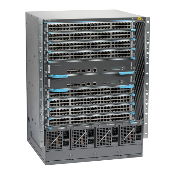
Juniper EX6210 Complete Hardware Manual (332 pages)
Brand:
Juniper
| Category:
Network Router
| Size: 17 MB
Table of Contents
Table of Contents
3
Revision
2
About the Documentation
17
Junos os Documentation and Release Notes
17
Documentation Conventions
17
Table 1: Notice Icons
17
Table 2: Text and Syntax Conventions
18
Documentation Feedback
19
Requesting Technical Support
19
Self-Help Online Tools and Resources
19
About the Documentation
19
Opening a Case with JTAC
20
Chapter 1 EX6210 Switch Overview
21
Switch and Components Overview and Specifications
21
Component Descriptions
21
Ex6210 Switch Overview
23
EX6210 Switch Hardware Overview
23
Software
23
Chassis Physical Specifications, LCD Panel, and Backplane
24
Figure 1: EX6210 Switch Front
24
Switch Fabric and Routing Engine Modules
25
Figure 2: EX6210 Switch Rear
25
EX6210 Switch Overview
25
Line Cards
26
Cooling System
26
Power Supplies
26
Table 3: EX6200 Line Cards
26
Table 4: Power Supplies Supported on EX6200 Switches
26
EX6210 Switch Configurations
27
Table 5: EX6210 Switch Hardware Shipping Configurations
27
Chassis Physical Specifications of an EX6210 Switch
29
Table 6: Physical Specifications of the EX6210 Switch Chassis
29
Understanding EX6210 Switch Component and Functionality Redundancy
30
Hardware Components that Provide Redundancy
30
Figure 3: EX6210 Switch
30
This Topic Describes
30
Routing Engine and Control Redundancy
32
Slot Numbering for an EX6210 Switch
32
Slot Numbering for SRE Module Slots and Line Card Slots
32
Table 7: Routing Engine and Control Redundancy for EX6210 Switches
32
Table 8: Slot Numbering for an EX6210 Switch
33
Slot Numbering for the Power Supply Slots
34
Figure 4: Slot Numbering for an EX6210 Switch
34
Table 9: Slot Numbering for Power Supply Slots on an EX6210 Switch Chassis
34
Line Cards
34
EX6210 Switch Hardware and CLI Terminology Mapping
35
Figure 5: Slot Numbering for Power Supply Slots on an EX6210 Switch Chassis
35
Table 10: CLI Equivalents of Terms Used in Documentation for EX6210
36
Switches
36
Cooling System
37
Component Descriptions
39
Chapter 2 Component Descriptions
39
Component Descriptions
39
LCD Panel in an EX6200 Switch
39
LCD Panel Modes
40
Figure 6: LCD Panel in an EX6200 Switch
40
LCD Panel Menus
41
Component Descriptions
41
Power Supplies
41
Table 11: LCD Panel Menu Options for the EX6200 Switch
42
Chassis Status Leds in an EX6200 Switch
44
Figure 7: Chassis Status Leds
44
Table 12: Chassis Status Leds in an EX6200 Switch
44
Field-Replaceable Units in an EX6210 Switch
45
Table 13: Frus in an EX6210 Switch
45
Switch Fabric and Routing Engine (SRE) Module in an EX6200 Switch
46
Figure 8: SRE Module in an EX6200 Switch
46
SRE Module Leds in an EX6200 Switch
48
Figure 9: SRE Module Leds in an EX6200 Switch
48
Uplink Port Leds in EX6200 Switches
49
Figure 10: Leds on the Uplink Port on an EX6200 Switch
49
Table 14: Link/Activity LED on an Uplink Port on EX6200 Switches
49
Management Port Leds in EX6200 Switches
50
Figure 11: Leds on the Management Port on an EX6200 Switch
50
Table 15: Status LED on an Uplink Port on EX6200 Switches
50
48-Port RJ-45 Line Card in an EX6200 Switch
51
Line Card Models
51
Figure 12: 48-Port RJ-45 Line Card
51
Table 16: Link/Activity LED on the Management Port on EX6200 Switches
51
Table 17: Status LED on the Management Port on EX6200 Switches
51
Line Card Components
52
48-Port Poe+ Line Card in an EX6200 Switch
52
Line Card Models
52
Figure 13: 48-Port Poe+ Line Card
52
Table 18: 48-Port RJ-45 Line Card Models
52
Line Card Components
53
48-Port SFP Line Card in an EX6200 Switch
53
Figure 14: 48-Port SFP Line Card
53
Table 19: 48-Port Poe+ Line Card Models
53
Line Card Models
54
Line Card Components
54
Line Card Leds in an EX6200 Switch
54
Figure 15: Line Card Leds on a 48-Port RJ-45 Line Card in an EX6200 Switch
54
Table 20: 48-Port SFP Line Card Model
54
Figure 16: Line Card Leds on a 48-Port Poe+ Card in an EX6200 Switch
55
Figure 17: Line Card Leds on a 48-Port SFP Line Card in an EX6200 Switch
55
Table 21: Status Leds on Line Cards for EX6200 Switches
55
Line Card Model and Version Compatibility in an EX6200 Switch
56
Network Port Leds in an EX6200 Switch
56
Figure 18: Network Port Leds on Line Cards
56
Table 22: Line Card Models by Junos os Release
56
Table 23: Network Port Leds on Line Cards in an EX6200 Switch-Link/Activity
57
Led
57
Table 24: Network Port Leds on Line Cards in an EX6200 Switch-Status
57
AC Power Supplies in an EX6200 Switch
58
Characteristics of an AC Power Supply
58
Figure 19: 2500 W AC Power Supply
58
Front
59
Figure 20: 5000 W AC Power Supply
59
Led
59
Table 25: Details of the 2500 W AC and 5000 W AC Power Supplies
59
AC Power Supply Power Cord Retainer
61
Figure 21: Power Cord Retainer for a 2500 W AC Power Supply
61
Power Supply Cover Panels
62
Figure 22: Power Cord Retainers for a 5000 W AC Power Supply
62
Table 26: Power Supply Cover Panels Used in EX6200 Switches
62
Power Supply Airflow
63
N+1 Redundancy Configuration of AC Power Supplies
63
Figure 23: Power Supply Cover Panels Used in EX6200 Switches
63
Table 27: N+1 Power Redundancy Configurations for Different EX6210 Switch Configurations Using 2500 W AC and 5000 W AC Power Supplies
64
N+N Redundancy Configuration of AC Power Supplies
65
Table 28: N+N Power Redundancy Configurations for Different EX6210 Switch Configurations Using 2500 W AC and 5000 W AC Power Supplies
66
AC Power Supply Leds in an EX6200 Switch
67
Figure 24: 2500 W AC Power Supply Leds
68
Figure 25: 5000 W AC Power Supply Leds
68
Table 29: Power Supply Leds
68
DC Power Supply in an EX6200 Switch
69
Figure 26: DC Power Supply
70
Table 30: N+1 Power Redundancy Configurations for Different EX6210 Switch Configurations Using 2100 W DC Power Supplies
71
DC Power Supply Leds in an EX6200 Switch
72
Table 31: N+N Power Redundancy Configurations for Different EX6210 Switch Configurations Using 2100 W DC Power Supplies
72
Figure 27: DC Power Supply Leds in an EX6200 Switch
73
Table 32: DC Power Supply Leds in EX6200 Switches
73
Cooling System and Airflow in an EX6210 Switch
74
Figure 28: Fan Tray for an EX6210 Switch
74
Figure 29: Airflow through the EX6210 Switch Chassis
75
Backplane in an EX6210 Switch
76
Component Specifications
77
Chapter 3 Component Specifications
77
USB Port Specifications for an EX Series Switch
77
Console Port Connector Pinout Information for an EX Series Switch
78
Table 33: EX Series Switches Console Port Connector Pinout Information
78
To DB-9 Serial Port Adapter Pinout Information for an EX Series
79
Switch
79
Table 34: EX Series Switches RJ-45 to DB-9 Serial Port Adapter Pinout
79
Information
79
Management Port Connector Pinout Information for an EX6200 Switch
80
Switches
80
Table 35: Management Port Connector Pinout Information for EX6200
80
Pluggable Transceivers Supported on EX6200 Switches
81
Table 36: Optical Interface Support and Copper Interface Support for Gigabit Ethernet SFP Transceivers in EX6200 Switches
82
Switches
87
Table 37: Optical Interface Support for SFP+ Transceivers in EX6200
87
Table 38: Optical Interface Support for EX6200-48F Line Cards
92
SFP+ Direct Attach Cables for EX Series Switches
99
Cable Specifications
100
Table 39: Software Support for SFP+ Passive Direct Attach Cables for EX Series Switches
100
Table 40: SFP+ Direct Attach Cable Specifications
101
Standards Supported by These Cables
103
Grounding Cable and Lug Specifications for EX6200 Switches
103
Figure 30: Location of Protective Earthing Terminal on an EX6210 Switch
104
Planning for Switch Installation
107
Site Preparation
109
Chapter 4 Site Preparation
109
Site Preparation Checklist for an EX6200 Switch
109
Table 41: Site Preparation Checklist
109
General Site Guidelines
111
Site Electrical Wiring Guidelines
111
Table 42: Site Electrical Wiring Guidelines
112
Environmental Requirements and Specifications for EX Series Switches
113
Table 43: EX Series Switch Environmental Tolerances
114
Rack and Cabinet Requirements
117
Chapter 5 Rack and Cabinet Requirements
117
Rack Requirements for an EX6210 Switch
117
Table 44: Rack Requirements and Specifications for an EX6210 Switch
117
Figure 31: Installing an EX6210 Switch in a Two-Post Rack
118
Cabinet Requirements and Specifications for an EX6210 Switch
119
Figure 32: Installing an EX6210 Switch in a Four-Post Rack
119
Clearance Requirements for Airflow and Hardware Maintenance for an EX6210
120
Switch
120
Table 45: Cabinet Requirements and Specifications for an EX6210 Switch
120
Figure 33: Airflow through the EX6210 Switch Chassis
121
Figure 34: Clearance Requirements for Airflow and Hardware Maintenance for
122
Cable Requirements
123
Chapter 6 Cable Requirements
123
Cables Connecting the EX6200 Switch to Management Devices
123
Table 46: Cable Specifications for Switch-To-Management-Device
123
Connections
123
Understanding EX Series Switches Fiber-Optic Cable Signal Loss, Attenuation
124
And Dispersion
124
Signal Loss in Multimode and Single-Mode Fiber-Optic Cable
124
Attenuation and Dispersion in Fiber-Optic Cable
124
Advertisement
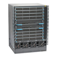
Juniper EX6210 Hardware Manual (354 pages)
Junos OSfor EXSeries EthernetSwitches
Brand:
Juniper
| Category:
Switch
| Size: 3 MB
Table of Contents
Table of Contents
3
About the Documentation
15
Documentation and Release Notes
15
Supported Platforms
15
Using the Examples in this Manual
15
Merging a Full Example
16
Merging a Snippet
16
Documentation Conventions
17
About the Documentation
17
Table 1: Notice Icons
17
Table 2: Text and Syntax Conventions
17
Documentation Feedback
19
Requesting Technical Support
19
Self-Help Online Tools and Resources
19
Opening a Case with JTAC
20
Overview
21
Interfaces Overview
21
Chapter 1 Interfaces Overview
23
Interfaces Overview
23
EX Series Switches Interfaces Overview
23
Network Interfaces
23
Special Interfaces
24
Table 3: Network Interface Types and Purposes
24
Table 4: Special Interface Types and Purposes
24
Understanding Interface Naming Conventions on EX Series Switches
26
Physical Part of an Interface Name
26
Logical Part of an Interface Name
28
Wildcard Characters in Interface Names
28
Understanding Aggregated Ethernet Interfaces and LACP
28
Link Aggregation Group (LAG)
29
Table 5: Maximum Interfaces Per LAG and Maximum Lags Per Switch
29
Link Aggregation Control Protocol (LACP)
30
ECMP Traffic
31
Understanding the Hashing Algorithm
31
IP (Ipv4 and Ipv6)
32
Table 6: Ipv4 and Ipv6 Hashing Fields
33
Mpls
34
Table 7: MPLS Hashing Fields
34
MAC-In-MAC Packet Hashing
35
Layer 2 Header Hashing
35
Table 8: MAC-In-MAC Hashing Fields
35
Table 9: Layer 2 Header Hashing Fields
35
Understanding How Energy Efficient Ethernet Reduces Power Consumption on
36
Interfaces
36
Understanding Local Link Bias
36
Figure 1: Egress Traffic Flow with Local Link Bias
37
Figure 2: Egress Traffic Flow Without Local Link Bias
37
Understanding Layer 3 Subinterfaces
38
Understanding Unicast RPF
39
Unicast RPF for Switches Overview
39
Unicast RPF Implementation
40
Unicast RPF Packet Filtering
40
Bootstrap Protocol (BOOTP) and DHCP Requests
40
Default Route Handling
40
When to Enable Unicast RPF
40
When Not to Enable Unicast RPF
41
Figure 3: Symmetrically Routed Interfaces
41
Limitations of the Unicast RPF Implementation on EX3200, EX4200, and EX4300 Switches
42
Figure 4: Asymmetrically Routed Interfaces
42
Understanding IP Directed Broadcast for EX Series Switches
43
IP Directed Broadcast for EX Series Switches Overview
43
IP Directed Broadcast Implementation for EX Series Switches
43
When to Enable IP Directed Broadcast
44
When Not to Enable IP Directed Broadcast
44
Understanding Interface Ranges on EX Series Switches
44
802.1Q Vlans Overview
46
Configuration
49
Part 2 Configuration
49
Chapter 2 Configuration Tasks
51
Configuring Gigabit Ethernet Interfaces (CLI Procedure)
52
Configuring VLAN Options and Interface Mode
52
Configuring the Link Settings
53
Configuration Tasks
53
Table 10: Factory Default Configuration Link Settings for EX Series Switches
53
Configuring the IP Options
54
Configuring Gigabit Ethernet Interfaces (J-Web Procedure)
55
Table 11: Port Edit Options
57
Table 12: Recommended Cos Settings for Port Roles
60
Port Role Configuration with the J-Web Interface (with CLI References)
61
Table 13: Port Role Configuration Summary
61
Table 14: Recommended Cos Settings for Port Roles
64
Adding a Logical Unit Description to the Configuration
65
Disabling a Physical Interface
65
Example: Disabling a Physical Interface
66
Disabling a Logical Interface
67
Configuring Flow Control
67
Configuring the Interface Address
68
Configuring Interface Ipv4 Addresses
69
Operational Behavior of Interfaces When the same Ipv4 Address Is Assigned to Them
70
Configuring Interface Ipv6 Addresses
71
Configuring the Interface Bandwidth
72
Configuring the Media MTU
73
Media MTU Overview
74
How to Configure the Media MTU
75
Encapsulation Overhead by Encapsulation Type
76
Table 15: Encapsulation Overhead by Encapsulation Type
76
Media MTU Sizes by Interface Type for M5 and M7I Routers with CFEB, M10 and M10I Routers with CFEB, and M20 and M40 Routers
77
Media MTU Sizes by Interface Type for M40E Routers
77
Table 16: Media MTU Sizes by Interface Type for M5 and M7I Routers with CFEB, M10 and M10I Routers with CFEB, and M20 and M40 Routers
77
Table 17: Media MTU Sizes by Interface Type for M40E Routers
77
Media MTU Sizes by Interface Type for M160 Routers
79
Media MTU Sizes by Interface Type for M7I Routers with CFEB-E, M10I Routers with CFEB-E, and M320 and M120 Routers
79
Table 18: Media MTU Sizes by Interface Type for M160 Routers
79
Table 19: Media MTU Sizes by Interface Type for M7I Routers with CFEB-E, M10I Routers with CFEB-E, and M320 and M120 Routers
79
Media MTU Sizes by Interface Type for MX Series Routers
80
Table 20: Media MTU Sizes by Interface Type for MX Series Routers
80
Media MTU Sizes by Interface Type for T320 Routers
81
Media MTU Sizes by Interface Type for T640 Platforms
81
Table 21: Media MTU Sizes by Interface Type for T320 Routers
81
Table 22: Media MTU Sizes by Interface Type for T640 Platforms
81
Media MTU Sizes by Interface Type for J2300 Platforms
82
Media MTU Sizes by Interface Type for J4300 and J6300 Platforms
82
Table 23: Media MTU Sizes by Interface Type for J2300 Platforms
82
Table 24: Media MTU Sizes by Interface Type for J4300 and J6300
82
Media MTU Sizes by Interface Type for J4350 and J6350 Platforms
83
Table 25: Media MTU Sizes by Interface Type for J4350 and J6350
83
Media MTU Sizes by Interface Type for EX Series Switches and ACX Series Routers
85
Media MTU Sizes by Interface Type for PTX Series Packet Transport Routers
85
Setting the Protocol MTU
85
Table 26: Media MTU Sizes by Interface Type for EX Series Switches and ACX
85
Table 27: Media MTU Sizes by Interface Type for PTX Series Packet Transport
85
Interface Ranges
86
Configuring Interface Ranges
87
Expanding Interface Range Member and Member Range Statements
89
Configuration Inheritance for Member Interfaces
90
Member Interfaces Inheriting Configuration from Configuration Groups
91
Interfaces Inheriting Common Configuration
93
Configuring Inheritance Range Priorities
93
Configuration Expansion Where Interface Range Is Used
93
Configuring Accounting for the Physical Interface
94
Applying an Accounting Profile to the Physical Interface
95
Example: Applying an Accounting Profile to the Physical Interface
95
Configuring Accounting for the Logical Interface
96
Applying an Accounting Profile to the Logical Interface
96
Example: Applying an Accounting Profile to the Logical Interface
96
Configuring Ethernet Loopback Capability
97
Configuring Gratuitous ARP
98
Configuring Static ARP Table Entries
99
Example: Configuring Static ARP Table Entries
99
Disabling the Transmission of Redirect Messages on an Interface
100
Configuring Restricted and Unrestricted Proxy ARP
100
Enabling or Disabling SNMP Notifications on Logical Interfaces
101
Configuring Aggregated Ethernet Links (CLI Procedure)
102
Configuring Aggregated Ethernet Interfaces (J-Web Procedure)
103
Table 28: Aggregated Ethernet Interface Options
104
Table 29: VLAN Options
105
Table 30: IP Options
105
Configuring Aggregated Ethernet LACP (CLI Procedure)
106
Configuring LACP Link Protection of Aggregated Ethernet Interfaces
107
Procedure)
108
Configuring LACP Link Protection at the Global Level
108
Configuring LACP Link Protection at the Aggregated Interface Level
108
Configuring Aggregated Ethernet Link Protection
109
Configuring Link Protection for Aggregated Ethernet Interfaces
109
Configuring Primary and Backup Links for Link Aggregated Ethernet
109
Interfaces
109
Reverting Traffic to a Primary Link When Traffic Is Passing through a Backup Link
110
Disabling Link Protection for Aggregated Ethernet Interfaces
110
Configuring Aggregated Ethernet Link Speed
110
Configuring Aggregated Ethernet Minimum Links
112
Configuring Energy Efficient Ethernet on Interfaces (CLI Procedure)
113
Enabling EEE on an EEE-Capable Base-T Copper Ethernet Port
113
Disabling EEE on a Base-T Copper Ethernet Port
113
Configuring Local Link Bias (CLI Procedure)
114
Configuring the Fields in the Algorithm Used to Hash LAG Bundle and ECMP Traffic (CLI Procedure)
114
Configuring the Hashing Algorithm to Use Fields in the Layer 2 Header for Hashing
115
Hashing
115
Hashing
116
Configuring Tagged Aggregated Ethernet Interfaces
116
Configuring a Layer 3 Subinterface (CLI Procedure)
117
Configuring Unicast RPF (CLI Procedure)
117
Disabling Unicast RPF (CLI Procedure)
119
Configuring IP Directed Broadcast (CLI Procedure)
120
Tracing Operations of an Individual Router or Switch Interface
121
Tracing Operations of the Interface Process
121
Configuration Tasks
51
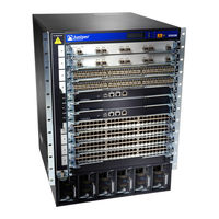
Juniper EX6210 Hardware Manual (404 pages)
Brand:
Juniper
| Category:
Switch
| Size: 10 MB
Table of Contents
Table of Contents
3
About the Documentation
13
Documentation and Release Notes
13
Using the Examples in this Manual
13
Merging a Full Example
14
Merging a Snippet
15
Documentation Conventions
15
Documentation Feedback
18
Requesting Technical Support
18
Self-Help Online Tools and Resources
19
Creating a Service Request with JTAC
19
EX8208 System Overview
21
EX8208 Switch Hardware Overview
21
Benefits of the EX8208 Switch
22
Software
22
Chassis Physical Specifications, LCD Panel, and Backplane
22
Routing Engines and Switch Fabric
23
Line Cards
24
Cooling System
25
Power Supplies
26
EX8208 Switch Configurations
27
EX8208 Switch Hardware and CLI Terminology Mapping
29
Chassis Physical Specifications of an EX8208 Switch
33
Field-Replaceable Units in an EX8208 Switch
35
EX8208 Chassis
37
Understanding EX8208 Switch Component and Functionality Redundancy
37
Hardware Components that Provide Redundancy
37
Routing Engine and Control Redundancy
38
Switch Fabric Redundancy
39
Slot Numbering for an EX8208 Switch
40
Slot Numbering for SRE and SF Module Slots and Line Card Slots
40
Slot Numbering for the Power Supply Slots
42
LCD Panel in an EX8200 Switch
43
LCD Panel Modes
44
LCD Panel Menus
45
Backplane in an EX8208 Switch
49
Chassis Status Leds in an EX8200 Switch
50
Network Port Leds in an EX8200 Switch
51
EX8208 Cooling System
53
Fan Tray
54
Airflow Direction in the EX8208 Switch Chassis
55
EX8200 Power System
56
AC Power Supply in an EX8200 Switch
56
AC Power Supply Description
57
N+1 Redundancy Configuration of AC Power Supplies
59
N+N Redundancy Configuration of AC Power Supplies
60
AC Power Supply Leds in an EX8200 Switch
63
AC Power Specifications for EX8200 Switches
65
AC Power Cord Specifications for an EX8200 Switch
66
DC Power Supply in an EX8200 Switch
70
DC Power Supply Leds in an EX8200 Switch
72
DC Power Specifications for EX8200 Switches
75
Grounding Cable and Lug Specifications for EX8200 Switches
76
EX8208 Host Subsystem
78
Switch Fabric and Routing Engine (SRE) Module in an EX8208 Switch
78
SRE Module Leds in an EX8208 Switch
80
Switch Fabric (SF) Module in an EX8208 Switch
81
SF Module Leds in an EX8208 Switch
82
EX8200 Line Cards
83
Line Card Model and Version Compatibility in an EX8200 Switch
84
8-Port SFP+ Line Card in an EX8200 Switch
86
Line Card Models
87
Line Card Components
87
40-Port SFP+ Line Card in an EX8200 Switch
88
Line Card Models
89
Line Card Components
90
Line Card Ports
90
EX8200-2XS-40P Line Card
92
Line Card Models
92
Line Card Components
93
Line Card Ports
93
EX8200-2XS-40T Line Card
94
Line Card Models
95
Line Card Components
95
Line Card Ports
96
EX8200-48PL Line Card
97
Line Card Models
97
Line Card Components
98
Line Card Ports
98
EX8200-48TL Line Card
99
Line Card Models
100
Line Card Components
100
Line Card Ports
100
48-Port SFP Line Card in an EX8200 Switch
101
Line Card Models
102
Line Card Components
102
48-Port RJ-45 Line Card in an EX8200 Switch
103
Line Card Models
104
Line Card Components
104
Line Card Leds in an EX8200 Switch
105
Site Planning, Preparation, and Specifications
107
Site Preparation Checklist for an EX8200 Switch
108
EX8208 Site Guidelines and Requirements
109
Environmental Requirements and Specifications for EX Series Switches
110
Switch or Device Altitude
111
EX2200-C no Performance
111
Degradation up to
111
5,000 Feet
111
Relative Humidity
111
In the Relative Humidity
111
In the Temperature Range
111
Range 10% through 85
111
32° F (0° C) through 113
111
General Site Guidelines
115
Site Electrical Wiring Guidelines
115
Clearance Requirements for Airflow and Hardware Maintenance for an EX8208 Switch
116
Rack Requirements
118
Cabinet Requirements
119
Power Requirements for EX8208 Switch Components
120
Calculating Power Requirements for an EX8208 Switch
121
Calculating the Power Consumption of Your EX8208 Switch Configuration
122
Calculating System Thermal Output for Your EX8208 Switch Configuration
124
Calculating the Number of Power Supplies Required for Your EX8208 Switch Configuration
124
EX8200 Network Cable and Transceiver Planning
128
Pluggable Transceivers Supported on EX8200 Switches
128
SFP+ Direct Attach Copper Cables for EX Series Switches
129
Cable Specifications
130
List of DAC Cables Supported on EX Series Switches
130
Standards Supported by These Cables
131
Understanding EX Series Switches Fiber-Optic Cable Signal Loss, Attenuation, and Dispersion
131
Signal Loss in Multimode and Single-Mode Fiber-Optic Cable
131
Attenuation and Dispersion in Fiber-Optic Cable
132
Calculating the Fiber-Optic Cable Power Budget for EX Series Devices
132
Calculating the Fiber-Optic Cable Power Margin for EX Series Devices
133
EX8200 Management Cable Specifications and Pinouts
135
Management Cable Specifications
135
Console Port Connector Pinout Information
136
USB Port Specifications for an EX Series Switch
136
RJ-45 Management Port Connector Pinout Information
137
RJ-45 to DB-9 Serial Port Adapter Pinout Information
138
Initial Installation and Configuration
139
Unpacking and Mounting the EX8208 Switch
140
Unpacking an EX8200 Switch
140
Unpacking a Line Card Used in an EX8200 Switch
143
Parts Inventory (Packing List) for an EX8208 Switch
144
Register Products-Mandatory to Validate Slas
147
Installing and Connecting an EX8208 Switch
147
Installing Adjustable Mounting Brackets in a Rack or Cabinet for an EX8200 Switch
148
Installing the Power Cord Tray in a Rack or Cabinet for an EX8200 Switch
151
Mounting an EX8208 Switch on a Rack or Cabinet
154
Mounting an EX8208 Switch on a Rack or Cabinet Using a Mechanical Lift
157
Mounting an EX8208 Switch on a Rack or Cabinet Without Using a Mechanical Lift
159
Connecting the EX8200 to Power
164
Connect Earth Ground to an EX Series Switch
164
Parts and Tools Required for Connecting an EX Series Switch to Earth Ground
165
Special Instructions to Follow before Connecting Earth Ground to an EX Series Switch
169
Connecting Earth Ground to an EX Series Switch
170
Connecting AC Power to an EX8200 Switch
171
Connecting DC Power to an EX8200 Switch
174
Powering on an EX8200 Switch
180
Connecting the EX8200 to External Devices
182
Connect a Device to a Network for Out-Of-Band Management
182
Connect a Device to a Management Console Using an RJ-45 Connector
183
Connecting an EX8200 Switch to a Modem
184
Setting the Serial Console Speed for the Switch
185
Configuring the Modem
186
Connecting the Modem to the Console Port
187
Connecting the EX8200 to the Network
188
Install a Transceiver
189
Connect a Fiber-Optic Cable
191
Configuring Junos os on the EX8200
193
EX8200 Switch Default Configuration
193
Connecting and Configuring an EX Series Switch (CLI Procedure)
194
Connecting and Configuring an EX Series Switch (J-Web Procedure)
198
Configuring the LCD Panel on EX Series Switches (CLI Procedure)
202
Disabling or Enabling Menus and Menu Options on the LCD Panel
203
Configuring a Custom Display Message
204
Dashboard for EX Series Switches
205
Graphical Chassis Viewer
206
System Information Panel
208
Health Status Panel
211
Capacity Utilization Panel
215
Alarms Panel
216
File System Usage
216
Chassis Viewer
216
Maintaining Components
234
Maintaining the EX8208 Cooling System
235
Removing a Fan Tray from an EX8208 Switch
235
Installing a Fan Tray in an EX8208 Switch
237
Maintaining the EX8200 Power System
238
Removing an AC Power Supply from an EX8200 Switch
239
Installing an AC Power Supply in an EX8200 Switch
240
Removing a DC Power Supply from an EX8200 Switch
243
Installing a DC Power Supply in an EX8200 Switch
245
Maintaining the EX8200 Power Cord Tray
247
Advertisement
Juniper EX6210 Hardware Manual (274 pages)
Brand:
Juniper
| Category:
Switch
| Size: 4 MB
Table of Contents
Revision
2
Table of Contents
5
About this Topic Collection
17
How to Use this Guide
17
List of EX Series Guides for Junos os Release 11.4
17
Component Descriptions
17
Downloading Software
19
Documentation Symbols Key
20
Documentation Feedback
21
Requesting Technical Support
22
Self-Help Online Tools and Resources
22
Opening a Case with JTAC
22
Chapter 1 EX4500 Switch Overview
23
Component Specifications
23
Switch and Components Overview and Specifications
23
EX4500 Switch Overview
25
EX4500 Switches Hardware Overview
25
Chassis
25
EX4500 Switches
26
Figure 1: EX4500 Switch Front
26
Figure 2: EX4500 Switch Rear with Intraconnect Module Installed
26
EX4500 Switch Overview
27
Figure 3: EX4500 Switch Rear with Virtual Chassis Module Installed
27
Intraconnect Module and Virtual Chassis Module
27
Power Supplies
28
Uplink Modules
28
EX4500 Switch Models
29
Table 1: EX4500 Switch Models, Components, and Supported Junos os
29
Identifying EX4500 Switch Models
31
Chassis Physical Specifications for EX4500 Switches
33
Front Panel of an EX4500 Switch
33
Table 2: Physical Specifications of the EX4500 Switch Chassis
33
Figure 4: EX4500 Switch Front Panel
34
Rear Panel of an EX4500 Switch
35
Figure 5: Label Identifying CEE Capable EX4500 Switches
35
Figure 6: EX4500 Switch Rear Panel with an Intraconnect Module Installed
36
Figure 7: EX4500 Switch Rear Panel with a Virtual Chassis Module Installed
36
EX4500 Switch Hardware and CLI Terminology Mapping
37
Table 3: CLI Equivalents of Terms Used in Documentation for EX4500
37
EX4500 Switches Hardware Overview
38
EX4500 Switches
38
Chapter 2 Component Descriptions
39
Component Descriptions
39
LCD Panel in EX4500 Switches
39
Figure 8: LCD Panel in EX4500 Switches
39
LCD Panel Modes
40
Component Descriptions
41
LCD Panel Menus
41
Table 4: LCD Panel Menu Options in EX4500 Switches
41
Chassis Status Leds in EX4500 Switches
44
Figure 9: Chassis Status Leds in an EX4500 Switch
44
Table 5: Chassis Status Leds in an EX4500 Switch
44
Field-Replaceable Units in EX4500 Switches
45
Figure 10: Network Port Leds
46
Network Port and Uplink Module Port Leds in EX4500 Switches
46
Figure 11: Uplink Module Port Leds
47
Table 6: Link/Activity LED on Network Ports and Uplink Module Ports in EX4500
47
Figure 12: Leds on the Management Port on an EX4500 Switch
48
Management Port Leds in EX4500 Switches
48
Table 7: Status LED on Network Ports and Uplink Module Ports in EX4500
48
AC Power Supply in EX4500 Switches
49
Table 8: Link/Activity LED on the Management Port on an EX4500 Switch
49
Table 9: Status LED on the Management Port on an EX4500 Switch
49
Figure 13: AC Power Supply
50
Figure 14: Power Cord Retainer for an AC Power Supply
50
AC Power Supply Leds in EX4500 Switches
51
Figure 15: AC Power Supply Leds in EX4500 Switches
51
Table 10: Power Supply LED on EX4500 Switches
51
DC Power Supply in EX4500 Switches
52
Figure 16: DC Power Supply
53
DC Power Supply Leds in EX4500 Switches
54
Figure 17: DC Power Supply LED in EX4500 Switches
54
Table 11: DC Power Supply LED on EX4500 Switches
54
Cooling System and Airflow in an EX4500 Switch
55
Figure 18: Fan Tray Used in an EX4500 Switch
55
Table 12: Airfow Direction in EX4500 Switch Models
55
Figure 19: Front-To-Back Airflow through the EX4500 Switch Chassis
56
Figure 20: Back-To-Front Airflow through the EX4500 Switch Chassis
57
Figure 21: Uplink Module Slots in an EX4500 Switch
58
Uplink Modules in EX4500 Switches
58
Figure 22: SFP+ Uplink Module
59
Table 13: Uplink Module Status LED
59
Figure 23: Intraconnect Module
60
Intraconnect Module in EX4500 Switches
60
Table 14: Intraconnect Module Status LED
60
Figure 24: Virtual Chassis Module
61
Virtual Chassis Module in EX4500 Switches
61
Figure 25: Virtual Chassis Module Leds
62
Table 15: Virtual Chassis Module Leds
62
Chapter 3 Component Specifications
63
Console Port Connector Pinout Information for an EX Series Switch
64
Table 16: EX Series Switches Console Port Connector Pinout Information
64
Management Port Connector Pinout Information for an EX4500 Switch
65
Table 17: Management Port Connector Pinout Information for EX4500
65
Switches
66
Table 18: Network Port and Uplink Module Port Connector Pinout Information for EX4500 Switches
66
Virtual Chassis Ports Connector Pinout Information for EX4500 Switches
67
Table 19: Virtual Chassis Ports (Vcps) Connector Pinout Information
67
Optical Interface Support in EX4500 Switches
70
Table 20: Optical Interface Support and Copper Interface Support for Gigabit Ethernet SFP Transceivers in EX4500 Switches
71
Table 21: Optical Interface Support for Gigabit Ethernet SFP+ Transceivers in
82
SFP+ Direct Attach Cables for EX Series Switches
86
Cable Specifications
87
Table 22: Software Support for SFP+ Direct Attach Cables for EX Series
87
Table 23: SFP+ Direct Attach Cable Specifications
88
Standards Supported by These Cables
90
Grounding Cable and Lug Specifications for EX4500 Switches
90
Component Specifications
63
USB Port Specifications for an EX Series Switch
63
Release
63
Planning for Switch Installation
93
Rack and Cabinet Requirements
93
Chapter 4 Site Preparation
95
General Site Guidelines
96
Site Electrical Wiring Guidelines
97
Table 25: Site Electrical Wiring Guidelines
97
Environmental Requirements and Specifications for EX Series Switches
98
Table 26: EX Series Switch Environmental Tolerances
99
Site Preparation
95
Site Preparation Checklist for EX4500 Switches
95
Table 24: Site Preparation Checklist
95
Chapter 5 Rack and Cabinet Requirements
101
Rack Requirements for EX4500 Switches
101
Table 27: Rack Requirements and Specifications for the Switch
101
Cabinet Requirements for EX4500 Switches
102
Clearance Requirements for Airflow and Hardware Maintenance for EX4500
102
Switches
103
Table 28: Cabinet Requirements and Specifications for the Switch
103
Figure 26: Front-To-Back Airflow through the EX4500-40F-FB Switch
104
Figure 27: Back-To-Front Airflow through the EX4500-40F-BF Switch
104
Figure 28: Clearance Requirements for Airflow and Hardware Maintenance for
105
Cable Requirements
107
Network Cable Specifications for EX4500 Switches
107
Chapter 6 Cable Requirements
107
Chapter 7 Planning Power Requirements
109
AC Power Specifications for EX4500 Switches
109
DC Power Specifications for EX4500 Switches
109
Table 29: Power Specifications for an AC Power Supply Used in EX4500
109
AC Power Cord Specifications for an EX4500 Switch
110
Table 30: Power Specifications for the DC Power Supply Used in an EX4500
110
Table 31: AC Power Cord Specifications for an EX4500 Switch
110
Figure 29: AC Plug Types
111
Chapter 8 Planning the Virtual Chassis
113
Understanding EX4200 and EX4500 Virtual Chassis Hardware
113
Configurations
113
Ports Used to Interconnect Virtual Chassis Members
113
Number of Switches, Required Software Releases, and Member Roles that You Configure in the Virtual Chassis
114
Table 32: Number of Switches and Switch Roles for an EX4200 Virtual Chassis
114
Table 33: Number of Switches and Switch Roles for an EX4500 Virtual Chassis
114
Table 34: Number of Switches and Switch Roles for a Mixed EX4200 and EX4500 Virtual Chassis, Per Junos os Release
114
Virtual Chassis Module-A Required Component for Virtual Chassis that Include EX4500 Switches
115
Switch Role and Member ID on the LCD Panel
115
Planning EX4200 and EX4500 Virtual Chassis
115
Table 35: Virtual Chassis Components to Consider When Planning an EX4200
115
Table 36: Cabling Requirements for a Virtual Chassis
116
Chapter 9 Installing the Switch
121
Parts Inventory (Packing List) for an EX4500 Switch
122
Unpacking an EX4500 Switch
122
Table 37: Inventory of Components Provided with an EX4500 Switch
123
Mounting an EX4500 Switch
124
Mounting an EX4500 Switch on Two Posts in a Rack or Cabinet
124
Figure 30: Attaching the Mounting Bracket Along the Front of the Switch
125
Figure 31: Mounting the Switch on Two Posts in a Rack
126
Mounting an EX4500 Switch on Four Posts in a Rack or Cabinet
126
Figure 32: Attaching the Front Bracket to the Switch Chassis
128
Figure 33: Mounting the Switch on the Front Posts in a Rack
128
Figure 34: Sliding the Rear Brackets to the Rear of a Four-Post Rack
129
Mounting an EX4500 Switch in a Recessed Position in a Rack or Cabinet
129
Chapter 10 Installing Switch Components
131
Installing an AC Power Supply in an EX4500 Switch
132
Figure 35: Installing a Power Supply in an EX4500 Switch
133
Installing a DC Power Supply in an EX4500 Switch
134
Figure 36: Installing a DC Power Supply in an EX4500 Switch
135
Installing a Fan Tray in an EX4500 Switch
135
Figure 37: Installing a Fan Tray in an EX4500 Switch
136
Figure 38: Uplink Module Slots in an EX4500 Switch
137
Installing an Uplink Module in an EX4500 Switch
137
Figure 39: Installing an Uplink Module in an EX4500 Switch
138
Installing an Intraconnect Module in an EX4500 Switch
139
Figure 40: Installing an Intraconnect Module in an EX4500 Switch
141
Installing a Virtual Chassis Module in an EX4500 Switch
141
Connecting a Virtual Chassis Cable to an EX4500 Switch
143
Figure 41: Installing the Virtual Chassis Module in an EX4500 Switch
143
Figure 42: Connecting a Virtual Chassis Cable to a Dedicated VCP on a Virtual
144
Installing a Transceiver in an EX Series Switch
144
Figure 43: Installing a Transceiver in an EX Series Switch
146
Chapter 11 Connecting the Switch
147
Connecting AC Power to an EX4500 Switch
153
Figure 46: Power Cord Retainer in an AC Power Supply
154
Connecting DC Power to an EX4500 Switch
155
Figure 47: Connecting the Power Supply Cord to an EX4500 Switch
155
Figure 48: Remove Plastic Cover from Terminal Block
157
Figure 49: Connecting the Power Supply Cables to an EX4500 Switch
158
Figure 50: Install Plastic Cover on Terminal Block
158
Connecting an EX Series Switch to a Network for Out-Of-Band Management
159
Figure 51: Ethernet Cable Connector
159
Connecting an EX Series Switch to a Management Console
160
Connecting an EX Series Switch to a Management Console Using
160
Figure 52: Connecting an EX Series Switch to a Network for Out-Of-Band
160
Console Port
161
Figure 53: Ethernet Cable Connector
161
Connecting an EX2200 Switch to a Management Console Using Mini-USB Type-B Console Port
162
Figure 54: Connecting an EX Series Switch to a Management Console through
162
Figure 55: Connecting an EX Series Switch Directly to a Management
162
Connecting an EX Series Switch to a Modem
163
Setting the Serial Console Speed for the Switch
163
Configuring the Modem
164
Connecting the Modem to the Console Port
165
Figure 56: Ethernet Cable Connector
165
Table 38: Port Settings
165
Connecting a Fiber-Optic Cable to an EX Series Switch
167
Figure 57: Connecting a Fiber-Optic Cable to an Optical Transceiver Installed in
167
Advertisement
Related Products
Juniper EX2500
Juniper EX2200-C-12T-2G
Juniper EX2200-C-12P-2G
Juniper EX2200-24T-4G
Juniper EX2200-24P-4G
Juniper EX2200-24T-4G-DC
Juniper EX2200-48T-4G
Juniper EX2200-48P-4G
Juniper EX3400
Juniper EX4600
Juniper Categories
Network Router
Switch
Gateway
Software
Network Hardware
More Juniper Manuals
Login
Sign In
OR
Sign in with Facebook
Sign in with Google
Upload manual
Upload from disk
Upload from URL