Table of Contents
Advertisement
Quick Links
SmartPAC 2 Press Automation Control
®
with Wintriss WPC Clutch/Brake Control
®
includes optional DiPro PAC and ProCam PAC
®
®
1126800 Rev. 1 September 2003
Tech Support Hotline
800-586-8324
8-5 EST
Wintriss
Wintriss Controls Group
100 Discovery Way
Acton MA 01720-3648 USA
Phone (978) 264-9550 (800) 586-8324
Fax (978) 263-2491
www.wintriss.com
PRINTED IN USA
DA70194
3
Advertisement
Table of Contents

Related Manuals for Honeywell SmartPAC 2


Summary of Contents for Honeywell SmartPAC 2
- Page 1 SmartPAC 2 Press Automation Control ® with Wintriss WPC Clutch/Brake Control ® includes optional DiPro PAC and ProCam PAC ® ® 1126800 Rev. 1 September 2003 Tech Support Hotline 800-586-8324 8-5 EST Wintriss Wintriss Controls Group 100 Discovery Way Acton MA 01720-3648 USA...
- Page 2 • Ensure that the press on which WPC clutch/brake control is used meets all of the OSHA and ANSI regulations for safeguarding press systems in installation and use. WPC is not in itself a safeguarding device. Honeywell takes no responsibility for injury if safeguarding devices are not installed or working properly.
- Page 3 Correct any problems before using the press. • Maintain all presses as stated in the applicable regulations. Honeywell takes no responsibility in cases where stopping mechanisms of machinery or other devices are not maintained or do not meet the applicable regulations or standards.
- Page 4 Honeywell Wintriss Product. We appreciate your business and want to do whatever we can to ensure your satisfaction. Wintriss products are built to stay on the job day after day, and are backed by an ironclad guarantee, international standards approvals, and unbeatable support.
-
Page 5: Table Of Contents
Table of Contents Chapter 1 – Introduction to SmartPAC 2 with WPC ......... 1 SmartPAC 2..............................1 WPC and Control Reliability........................1 SmartPAC with WPC ..........................2 How SmartPAC 2 with WPC Will Benefit Your Operation...............2 Standard features:...........................2 Optional Die Protection and Programmable Cam Switch Features: ............3 SmartPAC 2 Front Panel ..........................4... - Page 6 Connecting WPC’s Resolver to SmartPAC ..................74 Connecting Communications Between SmartPAC 2 and WPC............75 Connecting AC Wiring Between WPC and SmartPAC 2.................76 Connect Stop Circuits and Input Check Circuit to SmartPAC 2...............77 Setting Input Check Voltage Switch ....................77 Connecting SmartPAC 2 to a Network .....................79 Part 5 –...
- Page 7 Making the Connections ........................83 Connecting DiPro Sensor Interface to SmartPAC 2 .................90 Installing the DiPro Remote Connection Box ..................92 Set Up High Speed Version of SmartPAC 2 with WPC (Optional) ............94 Wiring Setup Mode Circuit ........................94 Wiring a Sensor-Disabled Output (Optional) ...................94 Part 6 –...
- Page 8 1126800 SmartPAC 2 with WPC Integration Chapter 3 – SmartPAC 2 Keyboard, Displays and Operating Modes ..171 Comparing SmartPAC 2 with Original SmartPAC.................173 SmartPAC 2 Keyboard ...........................174 Number Keys .............................176 Clear Key ............................177 Help Key ............................178 Cursor Keys............................179 ENTER and RESET Keys........................181 Program/Run Key Switch........................183...
- Page 9 Setting Link Motion ...........................268 Using a Servofeed Interface with Link Motion..................269 Using a Computer Keyboard to Enter Names..................270 Chapter 5 – SmartPAC 2 with WPC Program Mode ........273 SmartPAC 2 and Original SmartPAC.....................274 Entering and Exiting Program Mode ......................275 TOOL MANAGER ..........................276...
- Page 10 1126800 SmartPAC 2 with WPC Integration Chapter 5 – SmartPAC 2 with WPC Program Mode, continued Tool Program Menu..........................285 TOOL NAME or TOOL ID .......................286 COUNTERS............................286 Setting or Clearing the Counter Presets....................287 Setting or Clearing the Counter Values....................288 Clearing the Total Hits Preset Message....................288 Setting Counter Mode ........................288...
- Page 11 SmartPAC 2 with WPC Integration 1126800 Chapter 6 – SmartPAC 2 with WPC Run Mode, continued Settings Locked in Run Mode, or Password Required ................326 How to Use Hot Keys ..........................327 Toggle Hot Keys ..........................327 How to Program a Hot Key........................328 How to Delete a Hot Key ........................328...
- Page 12 Operating the Press Using One-hand Control ..................379 Operating the Press in BAR Mode......................380 Multiple Operator Stations........................380 Chapter 7 – SmartPAC 2 with WPC Fault Messages and Troubleshooting383 SmartPAC 2 and Original SmartPAC.....................384 What Happens When You Get a Fault Message ................385 How to Clear the Fault Message from the Display ................385...
- Page 13 SmartPAC 2 with WPC Integration 1126800 Chapter 7 – SmartPAC 2 with WPC Fault Messages and Troubleshooting, continued Messages Displayed Due to Press Control Problems, continued Miscellaneous Fault messages ......................416 Error Log ..............................418 E-mail Error Log and Other Information to Wintriss Tech Support ..........419 Using the WPC Input Status Display......................420...
- Page 14 Figure A. SmartPAC 2 PC Board Illustration Figure B. WPC LED Map Table A. Wintriss Clutch/Brake Control (WPC) Connector Pinouts Figure 1. Wintriss Clutch/Brake Control and SmartPAC 2 System Wiring Figure 2. Wintriss Clutch/Brake Control Operator Station A Wiring Figure 3. Wintriss Clutch/Brake Control External Wiring Figure 4.
- Page 15 Figure 1 - 3. How SmartPAC 2 Interprets Signals From a “Green” Sensor ............14 Figure 1 - 4. How SmartPAC 2 Interprets Signals From a Sensor Set to "Green Quick Check" ......15 Figure 1 - 5. How SmartPAC 2 Interprets Signals From a Sensor Set to "Green Constant" .......16 Figure 2 - 1.
- Page 16 Table 2 - 21. SmartPAC 2 Wiring: Spare 1 Port (5) and WPC Port (6) (TB105)..........168 Table 2 - 22. SmartPAC 2 Wiring: Spare 3 Port (7) and Spare 4 Port (8) (TB106) ........169 Table 2 - 23. SmartPAC 2 Wiring: Aux I/O (TB107) ..................169 Figure 3 - 1.
- Page 17 Figure 4 - 46. Alphabetic Entry Window ......................271 Figure 5 - 1. Program Mode Main Menu......................273 Figure 5 - 2. SmartPAC 2 and Original SmartPAC ...................274 Figure 5 - 3. Program Mode Main Menu......................276 Figure 5 - 4. Tool Manager..........................277...
- Page 18 Figure 5 - 42. Recalculate Setpoints Warning Box....................319 Figure 6 - 1. Run Menu............................321 Figure 6 - 2. SmartPAC 2 and Original SmartPAC ...................324 Figure 6 - 3. No Tool Loaded Warning ......................325 Figure 6 - 4. “Enter Your Password” Display....................326 Figure 6 - 5.
- Page 19 Figure 6 - 32. Toggle Hot Keys 1 and 2 ......................363 Figure 6 - 33. Mode Select Menu ........................365 Figure 7 - 1. SmartPAC 2 and Original SmartPAC ...................384 Figure 7 - 2. Error Code Box..........................385 Figure 7 - 3. Counter Preset Message Box ......................385 Figure 7 - 4.
- Page 20 Appendix C gives instructions for updating SmartPAC 2 program. Appendix D gives instructions for using SmartView remote viewing utility. Appendix E gives instructions for upgrading from an original SmartPAC to a SmartPAC 2. Appendix F gives instructions for replacing the SmartPAC 2 PC board.
- Page 21 SmartPAC 2 with WPC Integration 1126800 Important Highlighted Information Important danger, warning, caution and notice information is highlighted throughout the manual as follows: DANGER A DANGER symbol indicates an imminently hazardous situation, which, if not avoided, will result in death or serious injury.
- Page 22 90 days from date of shipment. Honeywell's obligations under this warranty are limited to repairing or replacing, at its discretion and at its factory or facility. Any products which shall, within the applicable period after shipment, be returned to Honeywell’s Wintriss Controls Group freight prepaid, and which are, after examination,...
-
Page 23: Chapter 1 - Introduction To Smartpac 2 With Wpc
SmartPAC 2 can be connected to a computer network, which enables users to see press parameters over the network and SmartPAC 2 to send email messages. -
Page 24: Smartpac With Wpc
SmartPAC 2 with WPC. Standard features: • All the settings are made at the operator console using SmartPAC 2's keyboard and large, bright, color display. • All settings for a tool are automatically saved in SmartPAC 2's non-volatile memory. To use the settings when you run the job again, simply re-load your stored tool number and you are ready to go. -
Page 25: Optional Die Protection And Programmable Cam Switch Features
1126800 • Upgrades and enhancements for SmartPAC 2 can be installed quickly and easily, either downloaded directly to SmartPAC 2 through the local network or by use of a convenient USB memory device (“USB disk”). • Interrupted Stroke provision: An Interrupted Stroke occurs when the press has been emergency-stopped before the completion of the stroke by either the operator or an automatic device for personnel or equipment protection. -
Page 26: Smartpac 2 Front Panel
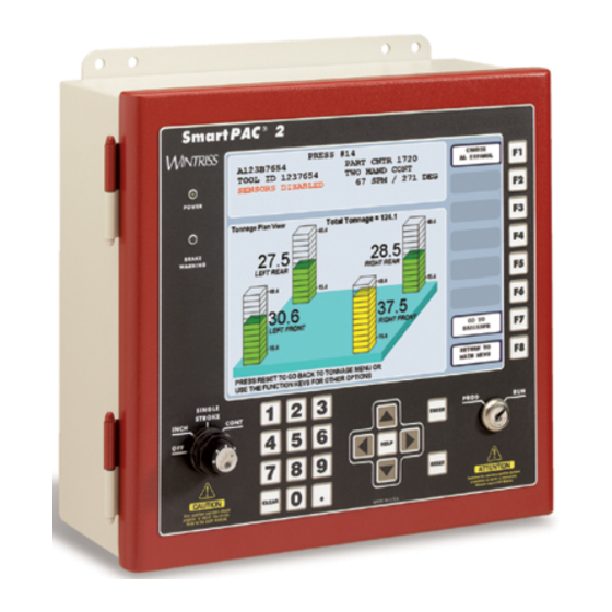
SmartPAC 2 with WPC Integration SmartPAC 2 Front Panel When you turn power on to SmartPAC 2, the crankshaft angle reading appears on the screen in Run mode. As soon as the press is running, the display switches to show the press speed. -
Page 27: System Components
• EMERGENCY STOP / RESET switch, which can be used to immediately stop the press. Either this switch or the RESET key on SmartPAC 2 resets WPC when a fault condition occurs. •... -
Page 28: Figure 1 - 2. Illustration Of Operator Station
1126800 SmartPAC 2 with WPC Integration • TOP STOP switch, which stops the ram at the top of stroke during continuous operation. • LEFT/RIGHT SELECT key switch for the ONE HAND trip mode, which is located on the bottom of the Operator Station (optional). -
Page 29: Wpc Options
SmartPAC 2 with WPC Integration 1126800 WPC Options Optional components also available with WPC include: • Counterbalance air pressure switch works the same as the clutch air pressure switch. However, this switch is used with the counterbalance air supply. It is required by OSHA regulations on presses with counterbalances. -
Page 30: How Smartpac 2 Works
The Resolver Lets SmartPAC 2 and WPC Know Where the Crankshaft Is SmartPAC 2 with WPC is connected to a resolver mounted on the press which turns one to one (1:1) with the crankshaft. Similar to an electrical generator, the resolver has windings inside and works on the principle of inductance. -
Page 31: Settings You Can Make On Smartpac 2
"good" parts if the die protection and/or tonnage monitoring option does not generate a fault. SmartPAC 2 has three batch counters that can be set to either top-stop the press or signal programmable limit switch (PLS) outputs when their presets... - Page 32 • Reset SmartPAC 2. You reset the unit after SmartPAC 2 stops the press when a malfunction is detected. SmartPAC 2 gives you specific fault messages for a malfunction, which makes it easy to troubleshoot.
-
Page 33: Sensors Available For Optional Dipropac
DiProPAC, the die protection option for SmartPAC 2, checks signals from sensors and sends a stop signal to the press when it detects a malfunction. Sensors connected to SmartPAC 2 are mounted to the press or die to monitor what is happening in the dies. -
Page 34: Understanding Sensor Terminology
"ready signal" because it is widely understood. To set a ready signal on SmartPAC 2, you just key in the degrees of the stroke where the sensor must actuate. The beginning point is called ready on. The end point is ready off. A separate ready signal can be set for each green sensor. -
Page 35: Impedance
When you make settings for a tool, you select the sensor type for each sensor connected to SmartPAC 2's sensor inputs. You can have any combination of reds, yellows, or greens for a tool. You will see how to select sensor type in Chapter 5 where you learn how to make sensor settings. -
Page 36: Figure 1 - 3. How Smartpac 2 Interprets Signals From A "Green" Sensor
(during the ready signal). An actuation is a closure to ground. If the sensor does not actuate, SmartPAC 2 sends a stop signal to the press. You can select an emergency stop, top stop or Smart Stop. - Page 37 However, a green quick check sensor cannot stay on or turn on outside the ready signal. The sensor must turn on, then turn off within the ready signal. Otherwise, SmartPAC 2 sends the stop signal to the press.
- Page 38 Stop signal sent at Stop Signal sent at immediately. signal. beginning of ready end of ready signal. signal. Figure 1 - 5. How SmartPAC 2 Interprets Signals From a Sensor Set to "Green Constant" Page 16 Chapter 1 Introduction to SmartPAC 2...
- Page 39 SmartPAC 2 with WPC Integration 1126800 Green Special CAUTION GREEN SPECIAL SENSOR MAY NOT PREVENT DAMAGE Use the green special sensor type with caution. It is not foolproof. It is possible that an undesirable number of slugs could stack up in an ejection hole, while still satisfying a green special sensor's requirements.
-
Page 40: Considerations For Setting Sensor Stop Type
SmartPAC 2 with WPC Integration Considerations for Setting Sensor Stop Type You can set the way SmartPAC 2 stops the press for each sensor — emergency stop, top stop, and Smart Stop. Here are a few general guidelines for how to set stop type. -
Page 41: Smartpac 2'S Three Modes Of Operation
SmartPAC 2 with WPC Integration 1126800 SmartPAC 2's Three Modes of Operation You can do various things with SmartPAC 2 depending on the mode you are in. • Initialization Mode. Used to make settings that generally only need to be made once after installation. -
Page 42: Specifications: Smartpac 2 With Wpc
1126800 SmartPAC 2 with WPC Integration Specifications: SmartPAC 2 with WPC SmartPAC 2 with SmartPAC 2 Enclosure 12.76" x 11.53" x 5.28" (324 x 293 x 134 mm), NEMA 12, shock mounted WPC Equipment SmartPAC 2 Panel mount 12.3" x 11.3" (312 x 287 mm) WPC Enclosure 16”... - Page 43 SmartPAC 2 with WPC Integration 1126800 Specifications: SmartPAC 2 with WPC Motor Additional WPC Forward and reverse contacts Inputs Shadow light curtains (2) Checks proper functioning at every stroke initiation and stop Customized Status Codes Four for E-stop Three for top stop...
- Page 44 1126800 SmartPAC 2 with WPC Integration Specifications: SmartPAC 2 with WPC SmartPAC 2 Communications Options, Connects via Ethernet to local area network and data viewed via the Internet using continued SmartView remote viewing utility Can connect to network running PACNet Computerized Pressroom Reporting* software Can be used with RSR ™...
-
Page 45: Chapter 2 - Installing Wpc And Smartpac 2
Ensure that there is one active operator station for each operator if you are using two-hand mode. Failure to comply with these instructions will result in death or serious injury. Installing SmartPAC 2 and WPC Chapter 2 page 23 SmartPAC 2 with WPC Integration... - Page 46 PROGRAMMABLE CAM SWITCH NOT FOR SAFETY USE Use SmartPAC 2’s programmable cam switch only to control auxiliary functions. The SmartPAC 2 programmable cam capability should never be used to provide timing signals for any safety use, including clutch/brake control or muting of light curtains.
- Page 47 SmartPAC 2 with WPC Integration 1126800 This chapter contains instructions for the following: Part 1 – Installation Overview, next section Part 2 – Install and Wire WPC, page 32 Part 3 – Install and Wire WPC Options, page 55 Part 4 – Install and Wire SmartPAC, page 69 Part 5 –...
-
Page 48: Part 1 - Installation Overview
See also Chapter 4 for Initialization mode, Chapter 5 for Program mode and Chapter 6 for Run mode. If you plan to install the SmartPAC 2 with WPC yourself instead of leaving the job to Wintriss service personnel, read this installation chapter entirely and carefully before you start. -
Page 49: The First Step - Checking The Press
Run flexible, liquid-tight conduit for high voltage lines (120V power, input check circuit, relay circuits) to the upper right-hand corner of SmartPAC 2 and to the upper right-hand corner of WPC. Run one or two low voltage conduits into the lower right- hand corner of SmartPAC 2 for the resolver and communications control wires. - Page 50 Good grounds at SmartPAC 2 and WPC are important. Make sure SmartPAC 2 and WPC are properly grounded. The ground wire from SmartPAC 2 should be connected to the main ground point of the press control. This may be in the area where the control transformer is grounded.
-
Page 51: Figure 2 - 1. Installation Overview
SmartPAC 2 with WPC Integration 1126800 Overrun limit sensor Crankshaft Timing chain Resolver Air pressure switch Motor Control Dual Safety Valve (DSV) Resolver, overrun limit sensor, and air pressure switch wiring wiring AC power SmartPAC 2 Wintriss Clutch/Brake Control Connections to... -
Page 52: Overview Of The Installation
Overview of the Installation Figure 2 - 1 on the preceding page shows SmartPAC 2 and WPC installed on a press. Study the drawing to get a general idea of what you will receive and what you will need to do. Of course, where you put the components (resolver, the SmartPAC 2 itself, etc.) will be different... -
Page 53: How To Terminate Cable Shields
NOTICE TERMINATE BOTH ENDS OF SHIELD Be sure to terminate the cable shields at both ends (for example, at SmartPAC 2 and DSI 2). Your Wintriss units have ground studs on the inside of the enclosure for terminating cable shields at the point of entry. -
Page 54: Part 2 - Install And Wire Wpc
1126800 SmartPAC 2 with WPC Integration Part 2 – Install and Wire WPC This part of chapter 2 describes how to mount and wire your Wintriss Clutch/Brake Control. It contains the following headings: Mounting the WPC Control Enclosure, next section... -
Page 55: Mounting The Wpc Control Enclosure
Refer to Figure 2 - 4 for mounting dimensions for the WPC control enclosure. It does not matter where you mount the control enclosure since the displays and keypad reside at SmartPAC 2. However, mount the WPC it so that it will be easy to make wiring connections and to perform maintenance, when necessary. -
Page 56: Install Wpc Without Enclosure
1126800 SmartPAC 2 with WPC Integration Install WPC Without Enclosure When you order WPC without enclosure, you receive the “control assembly”—the various processor boards that make up the basic system. See Figure 2 - 5, below, for mounting dimensions and clearances. -
Page 57: Wiring The Wpc
SmartPAC 2 with WPC Integration 1126800 Wiring the WPC WPC requires: • motor forward auxiliary contact (24V) • slide adjust monitor circuit (24V) • motor stop circuit (110V) if applicable, and • motor reverse auxiliary contact (24V) if applicable The power to WPC should come from the step-down control transformer and should be capable of handling 100 VA at 115 VAC ±... -
Page 58: Figure 2 - 6. Setting Voltage Selector Switch
1126800 SmartPAC 2 with WPC Integration local codes require it) is recommended for these circuits with a minimum 75°C temperature rating. To perform the wiring, follow these steps. 1. Locate the power supply board (situated under the main processor board). You will see the connector for AC power. -
Page 59: Installing And Wiring Dual Safety Valve And Sensors For Clutch And Counterbalance Air Pressure
SmartPAC 2 with WPC Integration 1126800 Installing and Wiring Dual Safety Valve and Sensors for Clutch and Counterbalance Air Pressure DANGER USER-SUPPLIED DUAL VALVE MAY NOT BE SUITABLE FOR SAFETY USE Ensure that your dual valve meets the applicable safety standards. Contact the valve manufacturer for information about your valve. -
Page 60: Air Pressure Sensors Or Switches
Air Pressure Sensors or Switches NOTICE Your SmartPAC 2 with WPC requires either sensors or switches to monitor clutch air pressure and counterbalance air pressure, if there is a counterbalance. See the instructions below to wire the sensors or switches:... - Page 61 SmartPAC 2 with WPC Integration 1126800 Counterbalance WPC terminal # Air Pressure Sensor Wire Color White Black See “Press Parameters,” page 229 in Chapter 4 to set the clutch and counterbalance air pressure values. NOTICE IF YOU USE RAMPAC TO CONTROL COUNTERBALANCE PRESSURE If you use RamPAC to control the counterbalance pressure, install a pressure switch and connect it to WPC as described in the next section.
- Page 62 1126800 SmartPAC 2 with WPC Integration 4. Connect the wires: For the counterbalance air pressure switch, refer to wiring diagram Figures 1 or 3 at the end of the manual. Wire the normally open terminals of the switch between WPC terminal #83 and ground.
-
Page 63: Install The Resolver
SmartPAC 2 with WPC Integration 1126800 Install the Resolver DANGER RESOLVER OUT OF SYNCH WITH CRANKSHAFT Retain the sprockets on the crankshaft and resolver shaft mechanically so they cannot ever shift or move out of radial alignment. Be sure the key on the resolver shaft retains the resolver sprocket. -
Page 64: Mounting And Wiring The Resolver
1126800 SmartPAC 2 with WPC Integration 2. Do not use gears, right angle joints, shafts with universal joints because these will develop too much backlash or too much play. 3. Do not try direct coupling to the crank because this requires extreme precision. If the resolver is only slightly off-center, the resolver bearing will be subjected to side loads well in excess of its rated capacity and will ultimately fail. -
Page 65: If You Replace Your Resolver
SmartPAC 2 with WPC Integration 1126800 keyway with the arrow before attaching the chain or other drive mechanism. See Figure 2 - 7, above, and Table 2 - 18, page 166. The press should be at top dead center when you do this. -
Page 66: Install The Overrun Limit Sensor Magnetic Switch
1126800 SmartPAC 2 with WPC Integration Install the Overrun Limit Sensor Magnetic Switch DANGER OVERRUN LIMIT SENSOR DOES NOT PROVIDE CORRECT TIMING • Install the overrun limit sensor so that the magnet is attached to a component, such as the crankshaft, that always moves with the motion of the press, regardless of the condition of the resolver or the resolver’s drive mechanism. -
Page 67: Planning Your Overrun Sensor Installation
SmartPAC 2 with WPC Integration 1126800 Planning Your Overrun Sensor Installation The overrun sensor consists of a magnetic switch and a magnet. The switch senses the presence of the magnet when the magnet is close to the end of the switch. See Figure 2 - 8 for an example of installing the overrun sensor magnetic switch and magnet. -
Page 68: Wiring The Overrun Sensor Magnetic Switch
1126800 SmartPAC 2 with WPC Integration Wiring the Overrun Sensor Magnetic Switch NOTICE You can run both the resolver wires and the overrun limit switch cable through the same conduit. If you do this, wait to cut the cable and wires until both the resolver and the overrun limit switch are installed. -
Page 69: Mounting And Wiring The Operator Station And Light Curtain(S)
SmartPAC 2 with WPC Integration 1126800 Mounting and Wiring the Operator Station and Light Curtain(s) DANGER NON-WINTRISS OPERATOR STATION MAY NOT MEET SAFETY REQUIREMENTS Ensure that the operator station run buttons are placed so that two hands are required to push both buttons at the same time and no one can press both buttons with one hand or with one hand and one elbow. -
Page 70: Figure 2 - 9. Operator Station, Side Buttons
1126800 SmartPAC 2 with WPC Integration 3. Plug the connector end of the cable into the operator station. 4. At the other end of the cable, connect the wires to the control enclosure main connector terminals, as shown in Table A at the end of the manual and wiring diagram Figure 2 at the end of this manual. -
Page 71: Using A Light Curtain On Your Press
SmartPAC 2 with WPC Integration 1126800 28.75 (730.3) 16.75 (425.5) MUTE MUTE EMERGENCY PRIOR PALM STOP TIME STOP 4.69 5.50 (119.1) (139.7) RESET 6.06 (154.0) Figure 2 - 10. Operator Station, Top Buttons Using a Light Curtain on Your Press... -
Page 72: Mounting The Operator Station If You Do Not Use Light Curtains
246). Connecting Other Wintriss Products to WPC Later in this chapter you will connect SmartPAC 2 to the WPC. You can also connect stop circuits of other products/monitors to WPC. To do so, follow the instructions in this section. - Page 73 SmartPAC 2 with WPC Integration 1126800 circuits, wire them between terminals #79 and #80 or between terminals #79 and #81. Refer to Figure 2 at the end of this manual for specific wiring schematics. Use customized status code wiring (see “Wiring WPC User Inputs,” page 52) when the auxiliary equipment that you are connecting does not have its own self-explanatory displays, as is available in DiPro 1500 or AutoSet load analyzers.
-
Page 74: Wiring Wpc User Inputs
1126800 SmartPAC 2 with WPC Integration Wiring WPC User Inputs DANGER USER INPUTS 1 THROUGH 7 NOT SUITABLE FOR SAFETY USE DO NOT use inputs 1 through 7 as part of any personnel protection system. These inputs are not control reliable. - Page 75 SmartPAC 2 with WPC Integration 1126800 The cross-checked pairs are inputs 8 & 9 and inputs 10 & 11. Each pair is programmable for ESTOP or ESTOP/LOCKOUT. These input pairs cause WPC to e-stop the press and generate errors under either of these conditions: One or both inputs in a pair are open.
- Page 76 1126800 SmartPAC 2 with WPC Integration Table 2 - 2. User Inputs (Interlocks), SmartPAC with WPC USER INPUT WIRE WIRE TO FAULT NAME OF STOP TYPE (INTERLOCK) (JUMPER TO CODE AUXILIARY BYPASS) PIN # EQUIPMENT User #1 +24 VDC User #2...
-
Page 77: Part 3 - Install And Wire Wpc Options
Mounting and Wiring the Bar Control Enclosure (Optional) , page 68 NOTICE HIGH SPEED OPTION FOR SMARTPAC 2 WITH WPC To set up the High Speed option for SmartPAC 2 with WPC, see “Set Up High Speed Version of SmartPAC 2 with WPC,” page 94 Wiring Lockout Relay (Optional) The lockout function in WPC provides an added safety feature to the product. -
Page 78: Wiring A Remote Reset Switch (Optional)
1126800 SmartPAC 2 with WPC Integration Wiring a Remote Reset Switch (Optional) The main WPC processor board has two terminals for wiring a remote reset switch. The remote reset terminal can be wired to the equipment that you choose, or you can just use a simple switch to activate the circuit. -
Page 79: Wiring Foot Switch (Optional)
SmartPAC 2 with WPC Integration 1126800 Wiring Foot Switch (Optional) DANGER UNGUARDED HAZARDS Ensure that light curtains and other safeguards are properly installed and operating to protect operators when using a foot switch. Failure to comply with these instructions will result in death or serious injury. -
Page 80: Installing One-Hand Control (Optional)
Follow all applicable OSHA and ANSI regulations when installing one-hand control. Ensure that proper safeguarding devices are installed and working properly. Honeywell takes no responsibility if safeguarding devices are not installed or working correctly. -
Page 81: Figure 2 - 12. One-Hand Control Switch Dimensions
SmartPAC 2 with WPC Integration 1126800 3.88 (98.6) 3.25 dia. (82.6) 4.00 top view (101.6) 2.50 dia. (63.5) Shroud Button Cover (114.3) side view Base Conduit opening Dimensions: inch (mm) Figure 2 - 12. One-hand Control Switch Dimensions Installing SmartPAC 2 and WPC... -
Page 82: Light Curtain Break" Mode
1126800 SmartPAC 2 with WPC Integration Install with 10-32 screws, 4 places 3.25 4.00 (82.6) (101.6) 2.69 (68.3) 3.88 (98.6) Dimensions: inch Figure 2 - 13. One-hand Control Switch Base, Showing Mounting Holes Connections diagram on this surface Figure 2 - 14. Wiring Connections in One-hand Control Switch (Switch Cover, Bottom View) “Light Curtain Break”... -
Page 83: Wiring One-Hand Control To Wpc
SmartPAC 2 with WPC Integration 1126800 One-hand Control will work with or without the “light curtain break” mode turned on (see (see ‘“Light Curtain Break” Mode,’ page 378 and “Switch 3 – One-hand Control or Foot Control,” page 243). With “light curtain break” on, you must press the One-hand Control button within eight seconds after removing your hand from the light curtain. -
Page 84: Wiring Automatic Single Stroke/External Trip
1126800 SmartPAC 2 with WPC Integration Wiring Automatic Single Stroke/External Trip DANGER PRESS STARTS UNEXPECTEDLY • Ensure that light curtains and other safeguards are properly installed and operating to protect operators when using automatic single stroke. Since the external trigger starts the stroke, a stroke can occur unexpectedly. -
Page 85: Installing Multiple Operator Stations
SmartPAC 2 with WPC Integration 1126800 Installing Multiple Operator Stations DANGER HAZARDS EXPOSED BY NON-WORKING OPERATOR STATION Safeguard the point of operation exposed by the non-working operator station when using multiple operator stations. This exposed area near a disabled operator station must be properly guarded. -
Page 86: Auxiliary Outputs (Optional)
1126800 SmartPAC 2 with WPC Integration Auxiliary Outputs (Optional) DANGER NON-SAFETY OUTPUTS USED FOR SAFETY FUNCTIONS Use auxiliary outputs 1, 2 and 3 for non-safety functions only. They cannot protect personnel from a moving hazard. You can use them for convenience in automation. -
Page 87: Wiring Auxiliary 2 Output (Optional)
SmartPAC 2 with WPC Integration 1126800 NOTICE In Inch mode, you can run a complete stroke without causing an Interrupted Stroke. Interrupted stroke is caused only when you release your hands from the run/inch buttons in the middle of the stroke. If you inch the entire stroke without releasing your hands, no Interrupted stroke is caused. -
Page 88: Wiring Auxiliary 3 Output (Optional)
Run mode lockout provided in SmartPAC. Refer to “Additional Security,” page 257, for more information. Wire your keylock switch between ground and SmartPAC 2 terminal #251 on TB107. • Switch CLOSED (grounded): prevents changes to any WPC settings in Program and Run modes •... -
Page 89: Installing Flywheel Speed Sensor (Optional Hardware Required)
SmartPAC 2 with WPC Integration 1126800 Installing Flywheel Speed Sensor (Optional Hardware Required) WARNING INJURY FROM MAGNETS THAT DETACH Mount the magnets with the brass screws provided. If you mount them with plastic screws or adhesive, the attaching means could fail and the magnets become dangerous projectiles, especially from high-speed presses. -
Page 90: Mounting And Wiring The Bar Control Enclosure (Optional)
1126800 SmartPAC 2 with WPC Integration Run wires from the cam switch through flexible, liquid-tight conduit to WPC. WPC is rated NEMA 12 (protected against dust and oil). Therefore, you must use conduit rated NEMA 12 and make proper conduit connections to ensure NEMA 12 protection. -
Page 91: Part 4 - Install And Wire Smartpac
Make sure the press has working top stop and emergency stop circuits. Verification that the press operates and stops properly is extremely important because SmartPAC 2 will be tied in to the press stop circuits. Do not forget to mark your electrical prints where you wire in SmartPAC 2. -
Page 92: Installing Smartpac 2 Enclosure
PLACE SMARTPAC 2 AT A CONVENIENT HEIGHT SmartPAC 2 should be installed at a convenient height for all users. An ideal height is to have the top edge of the unit approximately at chin level. Experiment to determine a good height for everybody before mounting. -
Page 93: Figure 2 - 18. Smartpac 2 Mounting Dimensions, Enclosure
Enclosure depth approx. 5.5 inches (140 mm). However, you must allow clearance of approximately 18 inches (460 mm) from mounting surface to fully open the enclosure’s door. Figure 2 - 18. SmartPAC 2 Mounting Dimensions, Enclosure Installing SmartPAC 2 and WPC... -
Page 94: Installing Smartpac 2 As A Panel Mount
Standard Enclosure Versus Optional Panel Mount SmartPAC 2 is available either with an enclosure or as a panel mount. The panel mount can be mounted from the inside or outside. Be sure to allow at least 6” (152 mm) of clearance behind the panel mounting plane to allow enough room for the electronics. -
Page 95: Figure 2 - 19. Smartpac 2 Mounting And Cutout Dimensions, Panel Mount
(270.5) (8.9) (8.9) 5.50 (139.7) 0.35 0.35 (8.9) (8.9) 4.50 (114.3) 9.00 (228.6) 8.65 (105.4) 10.70 (271.8) 11.00 (279.4) Figure 2 - 19. SmartPAC 2 Mounting and Cutout Dimensions, Panel Mount Installing SmartPAC 2 and WPC Chapter 2 page 73... -
Page 96: Wiring Between Wpc And Smartpac
AC power (connected at the top of each enclosure). If necessary, refer to these Figures to make the appropriate connections: • Figure 2 - 39, page 162 for the location of the SmartPAC 2 resolver connector; • Figure 1 at the end of the manual... -
Page 97: Connecting Communications Between Smartpac 2 And Wpc
Connecting Communications Between SmartPAC 2 and WPC Locate TB105 on the SmartPAC 2 board (Figure 2 - 39, page 162) and TB501 on the WPC Interface Board (Figure 2 - 38, page 161). See Figure 1 at the end of this manual for wiring. -
Page 98: Connecting Ac Wiring Between Wpc And Smartpac 2
• Do not connect the AC power source until you are done with all other installation procedures. • Turn off and disconnect power from the machinery SmartPAC 2 is connected to before making any wiring connections. This includes power to the machine control and motor. -
Page 99: Connect Stop Circuits And Input Check Circuit To Smartpac 2
• For SmartPAC 2 panel mount: Connect the ground wire to the ground stud that is on the face plate below the AC input terminal block. - Page 100 This signals SmartPAC 2 that the press ram should begin to move. If SmartPAC 2 gets no signals from the resolver within the start time limit (resolver not turning), it opens the emergency stop circuit. A “loss of rotation” fault message is displayed on the screen.
-
Page 101: Connecting Smartpac 2 To A Network
1126800 11. Make all the necessary conduit connections to ensure NEMA 12 protection. SmartPAC 2 is rated NEMA 12 (protected against dust and oil). Be sure to label all wires in a way consistent with your press’s electrical prints. Connecting SmartPAC 2 to a Network Before you can connect SmartPAC 2 to a computer network, your network administrator must make the necessary connections and settings. -
Page 102: Part 5 - Install Smartpac Options
WARNING ELECTRIC SHOCK HAZARD Turn off and disconnect power from SmartPAC 2 and from the machinery it is connected to before making any wiring connections. This includes power to the machine control and motor. Do not connect the AC power source until you are done with all other installation procedures. -
Page 103: Smartpac 2 With Wpc Integration
The following instructions describe how to add die protection and/or programmable cam switch capabilities to a basic SmartPAC 2 or upgrade your 8-cam or 8-sensor system to 16 cams or 16 sensors. After you install the board or boards, proceed to the appropriate wiring instructions, listed at the end of the installation steps. - Page 104 4. Refer to the following instructions to wire the option you just installed: • For ProCamPAC, see “Connecting Programmable Cam Channels,” next section. • For DiProPAC, refer to “Connecting DiPro Sensor Interface to SmartPAC 2,” page 90, or “Installing the DiPro Remote Connection Box,” page 92.
-
Page 105: Connecting Programmable Cam Channels
The assembly contains the relays that open and close on signals from SmartPAC 2 to turn your equipment on and off. Two different types of relays, mechanical and solid state, can be used depending upon the voltages of your equipment and your special needs. - Page 106 “C” and either the N/O or N/C side of the relay. If you connect to N/O, the equipment will be on for the degrees set on SmartPAC 2. If you connect to N/Ç the equipment will be on except for the degrees set. Generally, you use the N/O terminal;...
- Page 107 SmartPAC 2 with WPC Integration 1126800 Cam output 6.00 (152.4) 0.312 (7.9) dia. enclosure 4 places 10.00 (254.0) 10.75 (273.1) 3.50 (88.9) XX.XX = inches (XX.X) = mm 8.00 (203.2) 6.00 (152.4) Cam output board TB301 Connections to control DS301...
- Page 108 1126800 SmartPAC 2 with WPC Integration TB301 Connection to Control DS301 Solid State Relays Channels 5-8 LEDs for channels use only one relay (mechanical or solid state) for each channel Relay 8 Relay 7 Relay 6 Relay 5 Relay 4...
- Page 109 SmartPAC 2 with WPC Integration 1126800 Table 2 - 5. ProCamPAC to Cam Output Assembly TB301, Cams 1-8 8-cam: ProCamPAC TB401 (cams 1-8) Cam Output Board Wire or 16-cam: ProCamPAC TB451 (cams 1-8) TB301 (pin #) (pin #) CHAS (1)
- Page 110 1126800 SmartPAC 2 with WPC Integration Table 2 - 7. Making Connections to Relays Module How to connect Type Relay one wire to C; one wire to N/O or N/C; polarity does not matter SPDT DC Solid State – to C; + to N/O...
- Page 111 SmartPAC 2 with WPC Integration 1126800 ProCamPAC output relay Load Power Power Return RIGHT Suppressor ProCamPAC output relay Load Power Power Return Power Return ACCEPTABLE not prefered Suppressor ProCamPAC output relay Load Power Power Return WRONG Suppressor Figure 2 - 25. How to Connect Suppressors Across the Load...
-
Page 112: Connecting Dipro Sensor Interface To Smartpac 2
1126800 SmartPAC 2 with WPC Integration Connecting DiPro Sensor Interface to SmartPAC 2 You can connect your DiPro die protection sensors through the DSI 2 sensor interface. Refer to the DSI 2 manual for more information. Terminate cable shields to ground studs close to the point of entry into the enclosure. - Page 113 SmartPAC 2 with WPC Integration 1126800 Table 2 - 8. SmartPAC 2 to DSI 2 DiPro Sensor Interface, Sensors 1-8 SmartPAC 2 DiProPAC Wire DSI 2 (pin #) TB501 or TB551 (pin #) no connection GND (10) Black GND (291)
-
Page 114: Installing The Dipro Remote Connection Box
Installing the DiPro Remote Connection Box If you are using the DiPro RCB with your SmartPAC 2, it should be installed near the die opening of the press where it can easily be reached but also is protected from lubricant and coolant splash or drip. - Page 115 Sensor power Black * Provides power for electronic sensors used in inputs #1-3 (Lumberg connectors); 12 VDC; 100 mA total Table 2 - 11. DiPro RCB to SmartPAC 2 (continued) Wire RCB Sen. # SmartPAC 2 TB552 SmartPAC 2...
-
Page 116: Set Up High Speed Version Of Smartpac 2 With Wpc (Optional)
Set Up High Speed Version of SmartPAC 2 with WPC (Optional) If you have a standard SmartPAC 2 with WPC and wish to change the system to a high speed version (1600 SPM maximum), follow the steps below. If you have any difficulty, call Wintriss Tech Support.. -
Page 117: Part 6 - Set Up Smartpac2 With Wpc
Ensure that no die is mounted in the press during test and setup procedures. Failure to comply with these instructions could result in property damage. Turn On Power to SmartPAC 2 and WPC, next page Problems at Startup, page 98... -
Page 118: Turn On Power To Smartpac 2 And Wpc
SmartPAC 2 changes modes. To prevent this problem, before you turn the Program/Run key, make sure SmartPAC 2 is in the main menu for the mode it is in. If it is not, press RESET repeatedly until the main menu appears. - Page 119 To clear, turn the stroke select key to OFF and then back to the desired operating mode. • If another error message appears when SmartPAC 2 starts up, press RESET. • If the message still appears, find the error message in Chapter 7 and follow the instructions for correcting the problem.
-
Page 120: Problems At Startup
Power down SmartPAC 2 and WPC. Check that the connectors are correctly seated on both ends of the cables between the SmartPAC 2 PC board and the display. Power up SmartPAC 2 and WPC again. If the display remains off contact Wintriss Tech Support. - Page 121 SmartPAC 2 with WPC Integration 1126800 2. On the SmartPAC 2 PC board, locate the LEDs labeled “Tx6” and “Rx6” near TB105 (see Figure A at the end of the manual). • If both Tx6 and Rx6 blink, the SmartPAC 2 and WPC are communicating. Check the initialization menu again.
-
Page 122: Verify Proper Installation Of Procampac And/Or Dipropac Options
DiProPAC Options Figure 2 - 30. List of Installed Options If you installed ProCamPAC and/or DiProPAC into SmartPAC 2, you need to verify that the installation was done correctly and that these options appear on the screen. To do this, highlight “Installed Options” on the Initialization menu (see page 189 to enter Initialization mode). -
Page 123: Initialize Press Parameters
NOTICE Initializing the press control parameters resets them to their default settings. Initialize the press parameters only when you set up a new SmartPAC 2 with WPC or install new WPC firmware. When you first set up your SmartPAC 2 with WPC or when you install new WPC firmware, initialize the press parameters by following the steps below. - Page 124 1126800 SmartPAC 2 with WPC Integration WPC INITIALIZATION MENU USE THE CURSOR KEYS USER INTERLOCKS USER INTERLOCKS TO SELECT THE ITEM PRESS PARAMETERS YOU WISH TO SEE. PRESS OPTIONS PRESS ENTER TO INPUT STATUS ACCESS IT. PRESS RESET WHEN DONE.
-
Page 125: Create And Load A Test Tool Number
Create and Load a Test Tool Number To run your press after you install SmartPAC 2 with WPC, first create and load a test tool number. See Chapter 3 for how to use keyboard and display. See Chapter 5 for more information about programming a tool number. -
Page 126: Check And Set Direction Of Resolver Rotation
(refer to Figure 1 at the end of the manual): Swap the black and yellow wires at the WPC resolver connector TB105. Swap the black and white wires at the SmartPAC 2 resolver connector TB101. Inch the press again and watch the crank angle display. -
Page 127: Zero The Resolver
TDC. Use a dial indicator on the face of the ram or other means to ensure that the ram is at TDC. DO NOT use the crank angle reading on SmartPAC 2. If the press is not at TDC when you zero the resolver, the timing settings may be wrong. - Page 128 Turn the shaft until the key aligns as closely as possible with the arrow on the resolver housing, so the “Current Resolver Angle” reads close to 0° , preferably between 355° and 5° , but SmartPAC 2 can adjust for any angle between 330° and 30°. Go to step 2, below.
-
Page 129: Set Top Stop Angle And Install Overrun Magnet
SmartPAC 2 with WPC Integration 1126800 Set Top Stop Angle and Install Overrun Magnet DANGER INJURY DURING SETUP Keep all personnel away from the press during setup. Ensure that there is no die or other tooling in the press during setup. - Page 130 ENTER to toggle between OPEN and CLOSED. For more information about the switches, see “Setting Switches,” page 242. 3. Power down the SmartPAC 2 and power it up again to make the new switch settings take effect.
- Page 131 SmartPAC 2 with WPC Integration 1126800 Determine the Correct Top Stop Angle 1. Push and hold the run buttons so the press makes a full stroke and top stops. 2. The display shows the crank angle at which the press stopped. Write this angle in one of the boxes below.
- Page 132 1126800 SmartPAC 2 with WPC Integration Determine Top Stop Angle If Press Stopped BEFORE TDC (Between 181 ° ° ° ° and 360 ° ° ° ° ) If the press stopped , follow the steps below. Refer to the example given.
- Page 133 SmartPAC 2 with WPC Integration 1126800 3. Fill in the boxes below to find the Stopping Angle by subtracting the Old Top Stop Angle from the Angle the Press Stopped. ° ° ° – Angle the Press – Top Stop...
- Page 134 1126800 SmartPAC 2 with WPC Integration 6. Enter the New Top Stop Angle: Highlight the Top Stop Angle value and press ENTER. Adjust the setting by pressing the up and down cursor keys as required. When the New Top Stop Angle value shows in the display, press RESET and go to the next section.
- Page 135 SmartPAC 2 with WPC Integration 1126800 Determine Top Stop Angle if Press Stopped AFTER TDC (Between 0 ° ° ° ° and 180 ° ° ° ° ) If the press stopped , find and set the correct Top Stop Angle by following the AFTER TDC steps below.
- Page 136 1126800 SmartPAC 2 with WPC Integration 3. Fill in the boxes to find the New Top Stop Angle, by subtracting the Overshoot Angle from the Old Top Stop Angle. ° ° ° – Top Stop – Overshoot Top Stop Angle...
-
Page 137: Check Top Stop After You Change Top Stop Angle
SmartPAC 2 with WPC Integration 1126800 Check Top Stop After You Change Top Stop Angle Make sure the press is in INCH mode and the Prog/Run key points toward Run. Cycle the press several times and each time record the angle at which it stops. -
Page 138: Prepare To Install Magnet For Overrun Limit Sensor
1126800 SmartPAC 2 with WPC Integration Prepare to Install Magnet for Overrun Limit Sensor DANGER INJURY DURING SETUP Keep all personnel away from the press during setup. Ensure that there is no die or other tooling in the press during setup. - Page 139 To change a switch setting, highlight it and press ENTER to toggle between OPEN and CLOSED. Press RESET when done. 2. Power down SmartPAC 2 with WPC and power it up again. This makes the new switch settings take effect.
- Page 140 1126800 SmartPAC 2 with WPC Integration NOTICE • If you turn the Prog/Run key and nothing happens, press RESET repeatedly until the SmartPAC 2 changes modes. • If “PRESS CONTROL IS IN LOCKOUT MODE” appears on the display, turn the stroke select key to OFF and then back to the desired operating mode to clear the message.
- Page 141 To change a switch setting, highlight it and press ENTER to toggle between OPEN and CLOSED. Press RESET when done. 2. Power down SmartPAC 2 with WPC and power it up again. This makes the new switch settings take effect.
- Page 142 1126800 SmartPAC 2 with WPC Integration NOTICE • If you turn the Prog/Run key and nothing happens, press RESET repeatedly until the SmartPAC 2 changes modes. • If “PRESS CONTROL IS IN LOCKOUT MODE” appears on the display, turn the stroke select key to OFF and then back to the desired operating mode to clear the message.
- Page 143 To change a switch setting, highlight it and press ENTER to toggle between OPEN and CLOSED. Press RESET when done. 2. Power down SmartPAC 2 with WPC and power it up again. This makes the new switch settings take effect.
- Page 144 1126800 SmartPAC 2 with WPC Integration NOTICE • If you turn the Prog/Run key and nothing happens, press RESET repeatedly until the SmartPAC 2 changes modes. • If “PRESS CONTROL IS IN LOCKOUT MODE” appears on the display, turn the stroke select key to OFF and then back to the desired operating mode to clear the message.
- Page 145 To change a switch setting, highlight it and press ENTER to toggle between OPEN and CLOSED. Press RESET when done. 2. Power down SmartPAC 2 with WPC and power it up again. This makes the new switch settings take effect.
- Page 146 1126800 SmartPAC 2 with WPC Integration NOTICE • If you turn the Prog/Run key and nothing happens, press RESET repeatedly until the SmartPAC 2 changes modes. • If “PRESS CONTROL IS IN LOCKOUT MODE” appears on the display, turn the stroke select key to OFF and then back to the desired operating mode to clear the message.
-
Page 147: Install Magnet For Overrun Sensor
SmartPAC 2 with WPC Integration 1126800 Install Magnet for Overrun Sensor 1. Using double-sided foam tape or another means, temporarily install the blue magnet under the overrun sensor as shown in Figure 2 - 35. On the WPC processor board, look at the green LED in group #3, which should be on. -
Page 148: Check The On And Off Time Of The Overrun Sensor
1126800 SmartPAC 2 with WPC Integration WARNING INJURY FROM MAGNETS THAT DETACH Mount the magnets with the brass screws provided. If you mount them with plastic screws or adhesive, the attaching means could fail and the magnets become dangerous projectiles, especially from high-speed presses. -
Page 149: Part 7 - Perform Checkout Tests
NOTICE Use the “test tool” you created and loaded during setup procedures, page 103. NOTICE For help in using SmartPAC 2, see: Chapter 3 – Keyboard and Displays Chapter 4 – Initialization mode Chapter 5 – Program mode Chapter 6 – Run mode Before you operate your press, you must perform the tests in this section to verify that your Wintriss Clutch/Brake Control System is installed and set up correctly. - Page 150 1126800 SmartPAC 2 with WPC Integration Perform all the tests that apply to your SmartPAC 2 with WPC installation: WPC Power Supply Test, next page Check Safeguarding Devices, page 130 Check Dual Safety Valve (DSV) Wiring, page 132 Check the Emergency-Stop Circuit, page 134...
-
Page 151: Wpc Power Supply Test
SmartPAC 2 with WPC Integration 1126800 WPC Power Supply Test WARNING ELECTRIC SHOCK HAZARD WHEN WORKING INSIDE ENCLOSURE WITH POWER ON • DO NOT touch electrical connections or circuit boards. • Use test equipment only on the terminals specified in the instructions. -
Page 152: Check Safeguarding Devices
1126800 SmartPAC 2 with WPC Integration Check Safeguarding Devices DANGER INJURY DURING TESTING Keep all personnel away from the press during testing. Ensure that there is no die or other tooling in the press during testing. • Use extreme caution when testing moveable guards. Keep hands and other body parts outside the guarded area. - Page 153 If the press still does not stop, contact Wintriss Tech Support. 3. Close the guard you just tested, reset the SmartPAC 2 with WPC and repeat the process in step 2 for each moveable guard. When you have tested all the moveable guards, go on to the next test.
-
Page 154: Check Dual Safety Valve (Dsv) Wiring
2. On the WPC Power Supply board, remove one of the DSV fuses. (See Figure 2 - 36, page 159.) 3. Power up the press and SmartPAC 2 with WPC. Select INCH with the Stroke Select switch. Push both RUN/INCH buttons. Observe what happens. - Page 155 SmartPAC 2 with WPC Integration 1126800 7. Power down the press and press control. Replace the fuse you removed in step 5. 8. Power up the press and press control. Make sure the press is still in Inch mode. Push the RUN/INCH buttons briefly.
-
Page 156: Check The Emergency-Stop Circuit
1126800 SmartPAC 2 with WPC Integration Check the Emergency-Stop Circuit DANGER INJURY DURING TESTING Keep all personnel away from the press during testing. Ensure that there is no die or other tooling in the press during testing. Failure to comply with these instructions will result in death or serious injury. -
Page 157: Check The Top Stop Circuit
SmartPAC 2 with WPC Integration 1126800 Check the Top Stop Circuit DANGER INJURY DURING TESTING Keep all personnel away from the press during testing. Ensure that there is no die or other tooling in the press during testing. Failure to comply with these instructions will result in death or serious injury. -
Page 158: System Static Test
Display,” page 420. 1. Turn off the system air and bleed down the system (clutch) air pressure. 2. At the SmartPAC 2, set the Prog/Run key to RUN and the STROKE SELECT switch to INCH. 3. The display shows the crank angle. Notice whether the INTERRUPTED STROKE message flashes on the display. - Page 159 SmartPAC 2 with WPC Integration 1126800 9. Notice whether “F48” appears on the display. NOTICE If the E-stop and top stops are not connected according to Figure 2 (end of this manual), the status code may be different. Contact Wintriss Tech Support for assistance.
-
Page 160: Anti-Tiedown Test
1126800 SmartPAC 2 with WPC Integration Anti-tiedown Test DANGER INJURY DURING TESTING Keep all personnel away from the press during testing. Ensure that there is no die or other tooling in the press during testing. Failure to comply with these instructions will result in death or serious injury. -
Page 161: Anti-Repeat Test
SmartPAC 2 with WPC Integration 1126800 Anti-repeat Test DANGER INJURY DURING TESTING Keep all personnel away from the press during testing. Ensure that there is no die or other tooling in the press during testing. Failure to comply with these instructions will result in death or serious injury. -
Page 162: Shadow Light Curtain Test
1126800 SmartPAC 2 with WPC Integration Shadow Light Curtain Test WPC tests whether your Shadow(s) are working properly by momentarily de-energizing the Shadow transmitter whenever the press is started and stopped. WPC also ensures that the Emergency stop relays are open. - Page 163 SmartPAC 2 with WPC Integration 1126800 the receiver’s green and red indicators are still off, replace them. If none of these remedies corrects the problem, contact Wintriss Tech Support. 3. Block the light curtain. On the receiver, the green indicator should turn off and the red indicator should light up.
-
Page 164: Single Stroke Mode Test With Light Curtain
1126800 SmartPAC 2 with WPC Integration Single Stroke Mode Test with Light Curtain DANGER INJURY DURING TESTING Keep all personnel away from the press during testing. Ensure that there is no die or other tooling in the press during testing. - Page 165 SmartPAC 2 with WPC Integration 1126800 Inch the ram to the top and repeat the test, as described in this step. If the ram still does not make a full stroke or does not stop at top dead center, contact Wintriss Tech Support.
- Page 166 1126800 SmartPAC 2 with WPC Integration 7. Change to INCH mode and bring the ram to top dead center. 8. Change to SINGLE STROKE mode. 9. Momentarily press and release the RUN/INCH buttons. Observe the ram’s behavior. It should start moving when you press the buttons, then stop immediately when you release them.
-
Page 167: Single Stroke Mode Test Without Light Curtain(S)
SmartPAC 2 with WPC Integration 1126800 Single Stroke Mode Test Without Light Curtain(s) DANGER INJURY DURING TESTING Keep all personnel away from the press during testing. Ensure that there is no die or other tooling in the press during testing. - Page 168 1126800 SmartPAC 2 with WPC Integration • If the LED is blank or shows some other error, check and correct the wiring. After you correct the problem, run the test again, starting from step 2. If the ram still does not make a stroke or does not stop at top dead center, contact Wintriss Tech Support.
-
Page 169: Continuous Mode Test With Light Curtain
SmartPAC 2 with WPC Integration 1126800 Continuous Mode Test with Light Curtain DANGER IMPROPER SAFEGUARDING • Install safeguarding devices as needed to ensure operator safety. Follow the machine guarding requirements of OSHA standard 1910.217 and any other regulations and standards that apply. - Page 170 5. If it still does not stop immediately, contact Wintriss Tech Support. • If you have a SmartPAC 2 with WPC with the muting option, the ram should stop as soon as it reaches the non-muted part of the stroke (down stroke). This is acceptable.
-
Page 171: Continuous Mode Test Without Light Curtain(S)
SmartPAC 2 with WPC Integration 1126800 Continuous Mode Test Without Light Curtain(s) DANGER INJURY DURING TESTING Keep all personnel away from the press during testing. Ensure there is no die or other tooling in the press during testing. Failure to comply with these instructions will result in death or serious injury. - Page 172 1126800 SmartPAC 2 with WPC Integration 2. At the operator station, press the PRIOR ACT switch/indicator. The PRIOR ACT indicator should illuminate and then turn off eight seconds later. • If the switch/indicator does turn off in eight seconds, go to step 3.
-
Page 173: Foot Switch Test (With Optional Foot Switch)
Failure to comply with these instructions could result in death or serious injury. Perform this test only if your SmartPAC 2 with WPC is equipped with a Foot Switch. If necessary, refer to the LED map, Figure B at the end of the manual, when you are directed to the WPC control board. - Page 174 N/O” LED comes on when the Foot Switch is depressed. 6. Set Press Option switch 3 to CLOSED. Power down, then power up SmartPAC 2 with WPC to enable the change. You are now in the foot control mode. The press should cycle to top stop only if the Foot Switch is held down until after the Auto Carry-up angle.
-
Page 175: One-Hand Control Switchtests (With Optional One-Hand Control)
SmartPAC 2 with WPC Integration 1126800 One-hand Control Switch Tests (with Optional One- hand Control) DANGER INJURY DURING TESTING Keep all personnel away from the press during testing. Ensure that there is no die or other tooling in the press during testing. -
Page 176: Test For One-Hand Control With "Light Curtain Break" Mode
1. Set Press Option switch 3 to CLOSED. This enables “light curtain break” one-hand operation. Power down, then power up SmartPAC 2 with WPC to enable the change. 2. Set the STROKE SELECT switch to OFF and set the MODE to ONE HAND. Set the STROKE SELECT switch to SINGLE STROKE. -
Page 177: Test For One-Hand Control Without "Light Curtain Break" Mode
1. Set Press Option Switch 3 to OPEN. This enables normal one-hand operation. Power down, then power up SmartPAC 2 with WPC to enable the change. 2. Set the STROKE SELECT switch to OFF and set the MODE to ONE HAND. Set the STROKE SELECT switch to SINGLE STROKE. -
Page 178: Bar Mode Control Test - Optional
Refer to the WPC LED map, Figure B at the end of the manual. Perform this test if your SmartPAC 2 with WPC is equipped with the Bar Mode Control. 1. Set the STROKE SELECT switch to OFF and the MODE to TWO HAND. Set the STROKE SELECT switch to INCH. -
Page 179: User Inputs Test
Refer to “Wiring WPC User Inputs,” page 52. If you are not using any user inputs, go to the next section. Run the press. Actuate one of the user inputs. The press should stop and the SmartPAC 2 should display the appropriate fault code. -
Page 180: Part 8 - Pc Board Illustrations And Wiring Tables
Table 2 - 22. SmartPAC 2 Wiring: Spare 1 Port (5) and WPC Port (6) (TB105) Table 2 - 23. SmartPAC 2 Wiring: Spare 3 Port (7) and Spare 4 Port (8) (TB106) Table 2 - 24. SmartPAC 2 Wiring: Aux I/O (TB107) - Page 181 SmartPAC 2 with WPC Integration 1126800 + 24V Hi/Lo Speed DS150 J112 GREEN B-Proc DS151 B-PROC EPROM U125 B-PROCESSOR A-PROCESSOR Hi/Lo Speed GREEN J111 U109 A-PROC EPROM GREEN U108 GREEN A-Proc DS149 RESOLVER TB 105 GREEN Figure 2 - 36. WPC Processor Board...
- Page 182 1126800 SmartPAC 2 with WPC Integration Main Power Caution! TB401 Pow er Transformer Power 120V Volt. Switch Caution! 24 VDC Pow er Transformer Relay Fuses Caution! Relay Pow er Transformer D S404 Lockout Lockout Relay Figure 2 - 37. WPC Power Supply Board...
- Page 183 SmartPAC 2 with WPC Integration 1126800 Connector for Opt. Clock Display J506 Green (for Opt. Clock Display) Comms TB501 Operator mode outputs TB502 Figure 2 - 38. WPC Serial Interface Board Installing SmartPAC 2 and WPC Chapter 2 page 161...
- Page 184 224 225 226 227 228 229 230 231 232 233 234 235 236 237 238 239 240 241 242 243 244 Figure 2 - 39. SmartPAC 2 Board, Location of Components See Figure A at the end of the manual for a larger illustration...
- Page 185 SmartPAC 2 with WPC Integration 1126800 Sensors 1-8 TB501 TB551 LED s 1-8 Fuse Fuse F501 F551 Aux Out Aux Out TB550 TB500 LED s 9-16 Sensors 9-16 TB552 D iProPAC 8 board D iProPAC 16 board Figure 2 - 40. DiProPAC Boards, Location of Components...
- Page 186 1126800 SmartPAC 2 with WPC Integration Cams 1-8 TB401 TB451 Fuse Fuse F401 F451 Cams 9-16 TB452 ProCamPAC 8 board ProCamPAC 16 board Figure 2 - 41. ProCamPAC Boards, Location of Important Components 8-channel (left), 16-channel (right) Page 164 Chapter 2...
- Page 187 SmartPAC 2 will not recognize that the option is there. Eight and sixteen- channel configurations of the same option are interchangeable. When a board is installed in the correct location, SmartPAC 2 recognizes whether it is an 8- or 16- channel version of DiProPAC or ProCamPAC.
- Page 188 DSVA relay in DSVA relay out DSVB relay in DSVB relay out Lockout relay in Lockout relay out Lockout relay out Table 2 - 18. SmartPAC 2 Wiring: Resolver (TB101) SmartPAC 2 Resolver TB 101 Wire Color connections Pin #...
- Page 189 WPC Control TB102 Designation Board Terminal Pin # E-Stop E-Stop Top Stop Top Stop Table 2 - 20. SmartPAC 2 Wiring: SFI Port (1) and Module Port (2) (TB103) SmartPAC 2 Signal Port TB103 +RXD1 SFI PORT (1) –RXD1 “ TXD1 “...
- Page 190 PACNET PORT (4) –RXD4 “ TXD4 “ +TXD4 “ –TXD4 “ Table 2 - 22. SmartPAC 2 Wiring: Spare 1 Port (5) and WPC Port (6) (TB105) SmartPAC 2 TB105 Connections Port Pin # –TXD6 WPC PORT (6) +TXD6 “...
- Page 191 SmartPAC 2 with WPC Integration 1126800 Table 2 - 23. SmartPAC 2 Wiring: Spare 3 Port (7) and Spare 4 Port (8) (TB106) SmartPAC 2 TB106 Connections Port Pin # –TXD8 SPARE 2 PORT (8) +TXD8 “ TXD8 “ –RXD8 “...
- Page 192 1126800 SmartPAC 2 with WPC Integration Page 170 Chapter 2 Installing SmartPAC 2 and WPC...
-
Page 193: Chapter 3 - Smartpac 2 Keyboard, Displays And Operating Modes
While you are learning how to use SmartPAC 2, do not be afraid to try things. Push the keys. Select items on the displays. See what happens. You cannot hurt SmartPAC 2 by pushing a wrong key or making a wrong selection. - Page 194 1126800 SmartPAC 2 with WPC Integration This chapter contains the following instructions: Comparing SmartPAC 2 with Original SmartPAC, next section SmartPAC 2 Keyboard, page 174 SmartPAC 2 Display, page 186 The Three Operating Modes, page 188 Initialization Mode, page 190...
-
Page 195: Comparing Smartpac 2 With Original Smartpac
1126800 Comparing SmartPAC 2 with Original SmartPAC If you are familiar with the original SmartPAC, you will find using the SmartPAC 2 very similar. The figure below shows the differences between their front panels. Some of the instructions in this manual are based on those for the original SmartPAC. -
Page 196: Smartpac 2 Keyboard
1126800 SmartPAC 2 with WPC Integration SmartPAC 2 Keyboard The SmartPAC 2 keyboard is made up of number keys, cursor keys, function keys, a HELP key, a CLEAR key, an ENTER key, and a RESET key. HELP key ENTER SINGLE... -
Page 197: Figure 3 - 4. Stroke Select Key Switch
SmartPAC 2 with WPC Integration 1126800 Stroke Select Key Switch SmartPAC 2 CAMBIE AL ESPANOL Stroke Select POWER key switch BRAKE WARNING SINGLE STROKE INCH CONT SINGLE STROKE PROG INCH CONT ENTER HELP RESET CLEAR Figure 3 - 4. Stroke Select Key Switch Use the Stroke Select key switch to select OFF, INCH, SINGLE STROKE or CONT (continuous) mode of press operation. -
Page 198: Number Keys
1126800 SmartPAC 2 with WPC Integration Number Keys SmartPAC 2 CAMBIE AL ESPANOL Number keys POWER BRAKE WARNING PROG ENTER HELP RESET CLEAR CLEAR Figure 3 - 5. Number Keys Use the number keys to input numeric values, such as counter presets or tool numbers. -
Page 199: Clear Key
• To key in numbers: Use the number keys to place the number in the box; then press ENTER.. SmartPAC 2 will accept the number and close the entry box. • To key in letters: Use the cursor keys to highlight the desired letter, space or symbol;... -
Page 200: Help Key
1126800 SmartPAC 2 with WPC Integration Help Key SmartPAC 2 HELP key CAMBIE AL ESPANOL POWER BRAKE WARNING HELP PROG ENTER HELP RESET CLEAR Cursor (arrow) keys Figure 3 - 8. HELP Key The HELP key is at the center of the cursor keys. Press the HELP key any time you need more information about the display you are in. -
Page 201: Cursor Keys
SmartPAC 2 with WPC Integration 1126800 Cursor Keys SmartPAC 2 CAMBIE HELP key AL ESPANOL POWER BRAKE WARNING HELP PROG ENTER HELP RESET CLEAR Cursor (arrow) keys Figure 3 - 9. Cursor Keys and Help Key Use the cursor keys to move the highlight bar over the item on the display you want to select. - Page 202 1126800 SmartPAC 2 with WPC Integration If you have more than one column of items on a display, the highlight will move from the bottom of one column to the top of the next column. It will continue moving through all the columns (and keep repeating) until you release the cursor key.
-
Page 203: Enter And Reset Keys
To choose an item on a menu, use the cursor keys (see “Cursor Keys, above) to highlight the item you want on the menu. Then press the ENTER key. SmartPAC 2 goes to the display relating to the item you selected. -
Page 204: Figure 3 - 12. Reset Key
"Press Reset when done," or "Press Reset to cancel." To Reset SmartPAC 2 The RESET key is used to reset SmartPAC 2 when an error is generated or a counter preset is reached. When you press RESET, you are returned to the display where you were before the message appeared. -
Page 205: Program/Run Key Switch
• When you turn the key toward “Run,” SmartPAC goes into Run mode. • When you turn the switch toward “Prog,” it goes into Program mode. For more information about SmartPAC 2’s operating modes, see “The Three Operating Modes,” page188 and chapters 4, 5 and 6. -
Page 206: Function Keys
CLEAR Figure 3 - 13. Function Keys To the right of the SmartPAC 2 display are eight “Function keys,” also called “F keys.” In some screens you will be instructed to press function keys, also known as “F keys,” to perform certain tasks. -
Page 207: Hot Keys
F key next to the label describing the screen, and SmartPAC 2 goes to that screen. For detailed instructions on how to use Hot keys, see “How to Use Hot Keys,” page 327, in Chapter 6 – Run Mode. -
Page 208: Smartpac 2 Display
Figure 3 - 15. SmartPAC 2 Display, Run Mode The SmartPAC 2 display shows at the top a status box that contains information such as the press name and the press speed or angle. Below that is an area, the Run window, that contains menu items, instructions, graphics and other components. -
Page 209: Selecting An Item On A Display
To select an item on a menu, use the cursor keys to move the highlight bar until it highlights the item you want. Then press ENTER. Highlight the appropriate selection, and then press ENTER. SmartPAC 2 goes to the display you want, where you can make another selection or make a setting. In each display a message tells you what to do. -
Page 210: The Three Operating Modes Of Smartpac 2
SmartPAC 2 with WPC Integration The Three Operating Modes of SmartPAC 2 SmartPAC 2 has three modes of operation: Initialization, Program and Run. The figure below shows the main, or top, menu for each mode. Table 3 - 1, page 189 tells what each mode is for, how to enter the mode and how to exit it. -
Page 211: Table 3 - 1. Initialization, Program And Run Modes
Black text on light blue display. * If you turn the key and nothing happens, press RESET repeatedly until the SmartPAC 2 changes modes. To prevent this problem, before you turn the Program/Run key, make sure SmartPAC 2 is in the main (or top) menu for the mode it is in. -
Page 212: Initialization Mode
In Initialization mode, you make settings that affect the operation of SmartPAC 2 with any tool. (You program individual tools in the Program mode.) You use Initialization mode extensively when you install a new SmartPAC 2 and will likely use it only occasionally after you set it up and the press is running. -
Page 213: Figure 3 - 19. Navigation Example: Initialization Mode
SmartPAC 2 with WPC Integration 1126800 POSITION SENSOR MODE INITIALIZATION MODE MAIN MENU RESOLVER MOTION MODE PROGRAM ON/OFF RESOLVER ZERO TOOL NUMBER MODE PROGRAM TIMED OUTPUT POSITION SENSOR COUNTER SETUP MODE PROGRAM AUTO ADVANCE INSTALLED OPTIONS PROGRAM DSV ON select channel... -
Page 214: Program Mode
SmartPAC 2 menus in Program mode. See Chapter 5 for detailed instructions on how to use SmartPAC 2 in Program mode. For HELP press the HELP key located at the center of the cursor (arrow) keys. -
Page 215: Figure 3 - 21. Navigation Example: Program Mode
SmartPAC 2 with WPC Integration 1126800 STROKES BATCH 1 GOOD PARTS BATCH 2 BATCH 1 BATCH 3 BATCH 2 COUNTER INCREMENT ANGLES BATCH 3 F2 - ADVANCED MODES TOTAL HITS F2 - SET COUNTER MODES PARTS/STROKE STROKES/PART TOOL NAME COUNTERS... -
Page 216: Run Mode
Figure 3 - 22. Run Mode Main (Top) Menu When the press is running, SmartPAC 2 should be in Run mode. The crank angle clock diagram in the lower left corner of the display shows the rotation of the crankshaft. When the press is running in continuous mode, the press speed in strokes per minute is displayed in the center of the clock diagram. -
Page 217: Using Cursor Keys To Set Timing
Chapter 5, “DIE PROTECTION,” page 292, and “CAM SWITCH,” page 302. Usually you use one ON/OFF cycle for each cam. However, SmartPAC 2 enables you to set additional ON/OFF cycles for cams. You can set up to four ON/OFF cycles on one cam, with a maximum of six extra ON/OFF cycles distributed among all the cams. -
Page 218: Figure 3 - 24. Setting Cam Timing
1126800 SmartPAC 2 with WPC Integration that you programmed for a sensor and/or cam channel. The cursor keys graphically move a circular arc around this diagram. These cursor keys function in this way only when you have selected a display to make or change timing settings. See Chapter 5 for complete instructions on how to create a tool number and make all settings. -
Page 219: Figure 3 - 26. Setting On Angle
SmartPAC 2 with WPC Integration 1126800 2. Press the ( ) cursor key once. You will see a display similar to the following figure. The on/off box shows on at 1°, off at 0°, and the arc shows this graphically on the circle diagram. -
Page 220: Figure 3 - 27. Setting Off Angle
1126800 SmartPAC 2 with WPC Integration 4. To set the OFF angle use either the UP ( ) or DOWN ( ) cursor keys. In this example, press the DOWN ( ) cursor key. You can hold it down and the OFF edge of the arc will keep moving until you let up. -
Page 221: Screen Capture
SmartView (see “Appendix D – SmartView Remote Viewing and E-mail Setup,” page 455), you can e-mail a copy of any SmartPAC 2 screen to any of the e-mail recipients. If your SmartPAC 2 is not networked, you can save the screen capture to a USB disk as described on page 267. - Page 222 1126800 SmartPAC 2 with WPC Integration Page 200 Chapter 3 SmartPAC 2 Keyboard, Displays and Operating Modes...
-
Page 223: Chapter 4 - Smartpac 2 With Wpc Initialization Mode
You use Initialization mode extensively when you first install a new SmartPAC 2 and you will likely use this mode occasionally after you set up SmartPAC 2 and the press is running. In Initialization mode, you make initial settings that affect the operation of SmartPAC 2 regardless of which tool is loaded. -
Page 224: Smartpac 2 And Original Smartpac
All the options for SmartPAC work with SmartPAC 2. If you are familiar with the original SmartPAC, you will find using the SmartPAC 2 very similar. The figure below shows the differences between their front panels. Some of the instructions in this manual are based on the instructions for the original SmartPAC. -
Page 225: How To Enter And Exit Initialization Mode
If you turn the key and nothing happens, press RESET repeatedly until the SmartPAC 2 changes modes. To prevent this problem, make sure SmartPAC 2 is in the main (or top) menu for the mode it is in before you turn the Program/Run key. -
Page 226: Initialize Press Parameters
NOTICE SET THE INTERNAL CLOCK IN SMARTPAC 2 When you initialize your SmartPAC 2, be sure to set the clock to the correct date and your local time according to the instructions at “SET CLOCK,” page 266. Initialize WPC Press Parameters NOTICE Initializing the press control parameters resets them to their default settings. -
Page 227: Position Sensor
POSITION SENSOR choice in the main Initialization menu, a display appears similar to that in the next figure. You should disable the position sensor mode with a SmartPAC 2 – WPC integration system. To make this and other settings see the following sections: •... -
Page 228: Resolver Motion Mode (Normal Motion - Link Motion)
The default setting for this item is “Normal Motion.” This item controls whether SmartPAC 2 adapts to the action of a link-motion press. If this is a link-motion press, go to “Using SmartPAC 2 with a Link-Motion Press,” page 268, for instructions. -
Page 229: Table 4 - 1. Numeric And Alpha-Numeric Tool Number Modes
See “Appendix E – Upgrade from Original SmartPAC,” page 457 for more information about upgrading from original SmartPAC to SmartPAC 2. When you replace an original SmartPAC with SmartPAC 2 and transfer over the tool setup information, the existing tools will default to the Numeric mode. -
Page 230: Counter Setup Mode
Counter Setup Mode (INITIALIZATION – POSITION SENSOR) Depending upon how you wired SmartPAC 2, you can disable or enable the counter setup mode. (See “Wiring Setup Mode Circuit,” page 94.) If you performed this wiring, this made your SmartPAC 2 "setup-mode-ready.” This means that you can activate (enable) or deactivate (disable) the setup mode at this screen. -
Page 231: Installed Options
INSTALLED OPTIONS (INITIALIZATION – INSTALLED OPTIONS) This is a very useful display that indicates how your SmartPAC 2 has been configured. It includes firmware version numbers and the specific optional capabilities that have been installed. It also tells you how many cam channels and/or sensors you can connect to SmartPAC 2. -
Page 232: Press Name
You can use a separate computer keyboard to enter names. See page 270. You use this choice to name the press on which SmartPAC 2 is installed. When you select this item, a box opens that enables you to enter alphabetic characters, numbers and symbols. -
Page 233: Select Cam Names (Optional)
“custom-named” channel 1 as “bypass 3,” then channel 1 will always be “bypass 3” for every tool loaded. If your SmartPAC 2 is equipped with ProCamPAC, you can provide individual names for each of your cam channels to adequately describe their function. You can name up to 16 cam channels depending upon your SmartPAC 2 configuration. -
Page 234: Figure 4 - 8. Custom Name Entry Box
1126800 SmartPAC 2 with WPC Integration U N N A M E D SELECT NAME FOR "CUSTOM" NAME CAM CHANNEL 1 ACTIVATE GAG ADVANCE SLIDE USE THE CURSOR KEYS ANTI-BACK REL. TO CHOOSE A NAME. BYPASS 1 PRESS THE ENTER... -
Page 235: Auto Advance And Slow Rpm
SmartPAC 2 with WPC Integration 1126800 will always say “channel 1,” “channel 2,” etc. This is so that you always know which channel you are naming. However, the actual channel names will appear in Program and Run modes along with their respective channel numbers. -
Page 236: Setting Auto Advance Constant And Slow Rpm
When you determine the correct auto advance constant, you also need to identify the “Slow RPM,” or the slowest speed at which you will run your press. SmartPAC 2 uses that value as a starting point to begin the auto advance process. If the incorrect number was entered in “slow RPM,”... -
Page 237: Smartpac 2 With Wpc Integration
NOTICE AUTO ADVANCE IS ADJUSTABLE One of the nicest things about SmartPAC 2’s auto advance is that it is adjustable while the press is running. In other words, you can enter auto advance constants and a slow RPM value, and then run your press (see Chapter 6) to see how accurate they are. If you need to, you can tweak the values until you get them right. -
Page 238: Set Global Cams (Optional)
Events that remain the same on all tools can be programmed once as “global cams” and will apply to all the tools entered into this SmartPAC 2. This saves programming the same cam information for each tool and ensures that the cam always operates the same. -
Page 239: Figure 4 - 11. Global Cams, Select Cam Channel
SmartPAC 2 with WPC Integration 1126800 Figure 4 - 11. Global Cams, Select Cam Channel Asterisk (*) Indicates Global Cams 3. Select the cam you want to program. The following screen appears. Figure 4 - 12. Global Cam Timing Type 4. -
Page 240: Custom Sensor Names (Optional)
1126800 SmartPAC 2 with WPC Integration CUSTOM SENSOR NAMES (Optional) (INITIALIZATION – CUSTOM SENSOR NAMES) You select this choice to set custom sensor names (if DiProPAC is installed). You will see the screen shown in the next figure. NOTICE HOW YOU USE THE CUSTOM SENSOR NAMES You can create up to sixteen custom names for your sensors, regardless if you have DiProPAC-8 or DiProPAC 16. -
Page 241: Sensor Enable Mode (Optional)
You have to remember to do that yourself in Programming and Run modes. See “Disable (enable) sensors” discussed in both Chapter 5 and Chapter 6. If you want SmartPAC 2 to “remember” to re-enable sensors for you, choose one of the following “auto by” choices. -
Page 242: Enabling Or Disabling Setup Mode
(INITIALIZATION - SENSOR ENABLE MODE) NOTICE If your SmartPAC 2 is not integrated with a WPC, your inch-selector switch must be wired to the setup mode input, terminal #252 on TB107. If you enable Setup mode, the green sensors are disabled in the condition you choose: •... -
Page 243: Tool Information (Optional)
SmartPAC 2 with WPC Integration 1126800 2. Use the cursor keys to highlight the Setup Mode status. Press ENTER to change the status. The three choices are: DISABLED - Setup mode will never occur IN INCH - Setup mode occurs when the press is in Inch mode... -
Page 244: Figure 4 - 18. Tool Information Names
1126800 SmartPAC 2 with WPC Integration "CUSTOM" FEED LENGTH USE THE CURSOR KEYS FEED RATE TO CHOOSE A NAME. FEED ACCEL PRESS THE ENTER FEED SPEED KEY TO SELECT THE SHUT HEIGHT NAME. PASS LINE HT PRESS THE RESET LUBE TEMP. -
Page 245: Figure 4 - 20. Units Selection Menu
SmartPAC 2 with WPC Integration 1126800 Figure 4 - 20. Units Selection Menu Table 4 - 2. Units for Tool Information setup On-screen Units On-screen Units Abbreviation Abbreviation inches METERS meters feet FT/MIN feet per minute millimeters FT/SEC feet per second... -
Page 246: Figure 4 - 21. Completed Tool Number Information Screen
1126800 SmartPAC 2 with WPC Integration NAME UNITS PLACES TOOL 1 PASS LINE HT PASS LINE HT INFO. 2 STRAIGHTENER NAMES 3 HYD. OVLD. TONS 4 PRESS SPEED 5 CONVEYOR 6 PART LUBE USE CURSOR KEYS TO SELECT A NAME. PRESS ENTER TO CHANGE. -
Page 247: Press Control
SmartPAC 2 with WPC Integration 1126800 PRESS CONTROL [INITIALIZATION – PRESS CONTROL] Figure 4 - 22. Press Control Initialization Mode The WPC Initialization menu enables you to perform the following procedures: • Set up the user interlocks, “User Interlocks,” next section •... - Page 248 1126800 SmartPAC 2 with WPC Integration DANGER USER INPUTS ADD DELAY TO STOPPING TIME DO NOT connect light curtains or other presence-sensing devices to any user inputs. Cross-checked input pairs (8 & 9 and 10 & 11), though control reliable, are suitable only for such applications as connecting to safety switches used with interlocking barrier guards.
-
Page 249: Figure 4 - 23. "User Interlock" Display
SmartPAC 2 with WPC Integration 1126800 Input pairs 8 & 9 and 10 & 11 are always activated and cannot be turned off. If you do not want to use one or both pairs of inputs, leave them wired to ground, as indicated in Table 2 - 2, page 54 in the Installation chapter. -
Page 250: Figure 4 - 24. "Select Name" Display
1126800 SmartPAC 2 with WPC Integration See Table 4 - 4, below, for a complete list of pre-programmed names. Select “CUSTOM NAME” if you want to enter a name not on the list. UNNAMED UNNAMED SELECT STOP TYPE CUSTOM NAME BEARING TEMP. -
Page 251: Press Parameters
SmartPAC 2 with WPC Integration 1126800 5. Repeat steps 2 through 4, for the user inputs you will use. 6. When you are completely done, press RESET twice to return to the Main Initialization menu. Press Parameters (INITIALIZATION – PRESS CONTROL – PRESS PARAMETERS) Figure 4 - 25. -
Page 252: Stop Limit
1126800 SmartPAC 2 with WPC Integration Stop Limit (INITIALIZATION – PRESS CONTROL – PRESS PARAMETERS) DANGER INCORRECT SAFETY DISTANCE DUE TO INCORRECT STOP TIME • Perform a 90 ° Stop Test any time you change the stop time limit. (See “Performing the 90 °... -
Page 253: Figure 4 - 26. Selecting "Brake Monitor" From Smartpac's Run Menu
SmartPAC 2 with WPC Integration 1126800 TOOL NUMBER 1234567 PART CNTR CHAIR BRACKET SENSORS ENABLED USE THE CURSOR KEYS DISABLE SENSORS TO MAKE SELECTIONS. COUNTERS PRESS ENTER TO BRAKE MONITOR BRAKE MONITOR ACCESS SELECTION. DIE PROTECTION CAM SWITCH TOOL INFORMATION... -
Page 254: Setting Stop Time Limit At Press Parameters
Initialization menu appears. Select “Press Options.” In the menu that appears, set Switch 7 to OPEN to enable changes (see page 247). Power down SmartPAC 2 with WPC and power it up again to make the new switch setting take effect. -
Page 255: Smartpac 2 With Wpc Integration
SmartPAC 2 with WPC Integration 1126800 WPC INITIALIZATION MENU USE THE CURSOR KEYS USER INTERLOCKS USER INTERLOCKS TO SELECT THE ITEM PRESS PARAMETERS YOU WISH TO SEE. PRESS OPTIONS PRESS ENTER TO INPUT STATUS ACCESS IT. PRESS RESET WHEN DONE. -
Page 256: Setting The Start Time Limit At Press Parameters
1126800 SmartPAC 2 with WPC Integration Power down SmartPAC 2 with WPC and power it up again to make the new switch setting take effect. About the 90° stop-time test The 90° stop-time test is required in order to set the proper safety distance for personnel guarding devices including light curtains, two-hand controls, and type-B movable barriers. -
Page 257: Using Auto Carry-Up
SmartPAC 2 with WPC Integration 1126800 Using Auto Carry-up DANGER INCORRECT AUTO CARRY-UP ANGLE • Ensure that the Auto Carry-up angle is correct. If the operator can reach the pinch point, the Auto Carry-up angle must be set so that any hazardous openings are smaller than ¼” by the time the crankshaft reaches the Auto Carry-up angle. -
Page 258: Setting Auto Carry-Up Angle
The WPC Initialization menu appears. Select “Press Options.” In the menu that appears, set Switch 7 to OPEN to enable changes (see page 247). Power down SmartPAC 2 with WPC and power it up again to make the new switch setting take effect. -
Page 259: Figure 4 - 31. "Micro-Inch" Display
SmartPAC 2 with WPC Integration 1126800 However, no matter how long you hold the buttons, the clutch is engaged only for the Micro- inch time you set. You can stop the ram before the set time by releasing the switches. To jog the ram through a complete stroke, press and release the RUN/INCH switches as many times as necessary. -
Page 260: Setting Clutch And Counterbalance Air Pressure Limits
1126800 SmartPAC 2 with WPC Integration Setting Clutch and Counterbalance Air Pressure Limits WPC usually uses pressure sensors to monitor both clutch air and counterbalance pressure levels. (Optionally, you can use pressure switches.) You can set a minimum lower limit for your clutch air pressure. -
Page 261: Setting Shutdown And Flywheel Timer Limits (Optional)
SmartPAC 2 with WPC Integration 1126800 Setting Shutdown and Flywheel Timer Limits (Optional) You can set these two optional features under “Press Control.” They are "Shutdown Limit" and "Flywheel Timer." Description of Shutdown Limit NOTICE The Auto Compensated Top Stop ("ACTS") firmware option for WPC is required for "Shutdown Limit"... -
Page 262: Setting The Acts Angle (Optional)
1126800 SmartPAC 2 with WPC Integration PRESS CONTROL PARAMETER MENU TOP STOP DEFLT 220 DEG CARRYUP ANGLE 149 DEG MICRO TIME 100 MSEC MICRO ANGLE 185 DEG MAIN AIR LIMIT 0 PSI CNTR BAL +/- 0 PSI STOP LIMIT 250 MSEC... -
Page 263: Initialize Parameters
SmartPAC 2 with WPC Integration 1126800 Initialize Parameters NOTICE INITIALIZE WPC PARAMETERS BEFORE PROGRAMMING YOUR SMARTPAC 2/WPC When you set up a new SmartPAC with WPC, initialize the WPC (press) parameters before you start programming your unit. See Chapter 2, page 101. NOTICE... -
Page 264: Setting Switches
• Make sure that you program all eight Press Option switches properly at SmartPAC. • After you change switch settings, power down the SmartPAC 2/WPC. Power it up again to enable the new settings. If you do not this, the previous switch settings will remain in effect. -
Page 265: Table 4 - 6. Switch 3 Settings For One-Hand Control Or Foot Switch Mode
Switch 3 – One-hand Control or Foot Switch Mode NOTICE After you change switch settings, power down the SmartPAC 2/WPC. Power it up again to enable the new settings. If you do not this, the previous switch settings will remain in effect. -
Page 266: Table 4 - 7. Switch 4 Settings For Auto Compensated Top Stop
Switch 4 – Auto Compensated Top Stop (“ACTS”) Enabled (Optional) NOTICE After you change switch settings, power down the SmartPAC 2/WPC. Power it up again to enable the new settings. If you do not this, the previous switch settings will remain in effect. -
Page 267: Table 4 - 8. Switch 5 Setting For Prior Act Timing
Demand NOTICE After you change switch settings, power down the SmartPAC 2/WPC. Power it up again to enable the new settings. If you do not this, the previous switch settings will remain in effect. Option Switch 5 sets the prior act timing for Automatic Single Stroke mode and for Continuous on Demand mode. -
Page 268: Table 4 - 9. Switch 6 Setting For Single Or Dual Light Curtains
Switch 6 – Dual Light Curtain Enabled NOTICE After you change switch settings, power down the SmartPAC 2/WPC. Power it up again to enable the new settings. If you do not this, the previous switch settings will remain in effect. - Page 269 Switch 7 –Disable Changes to Stop Time Limit and Auto Carry-up Angle NOTICE After you change switch settings, power down the SmartPAC 2/WPC. Power it up again to enable the new settings. If you do not this, the previous switch settings will remain in effect.
-
Page 270: Table 4 - 11. Switch 8 Settings For Top Stop With F And H Errors
Interrupted Stroke NOTICE After you change switch settings, power down the SmartPAC 2/WPC. Power it up again to enable the new settings. If you do not this, the previous switch settings will remain in effect. Switch 8 controls two different functions: •... -
Page 271: Operator Mode Settings On Press Control Option Switch Screen
SmartPAC 2 with WPC Integration 1126800 Table 4 - 12. Switch 8 Setting for Auxiliary 1 Response to Interrupted Stroke Option Switch 8 Setting Auxiliary Output 1 Turns OFF when one of the following occurs: • an Interrupted Stroke* condition OPEN •... -
Page 272: Input Status
2. Press RESET to exit. Input Status [INITIALIZATION – PRESS CONTROL – INPUT STATUS] The items on this menu are useful for troubleshooting SmartPAC 2 with WPC. See the instructions in Chapter 7, starting on page 420. Page 250 Chapter 4... -
Page 273: Security Access
Use the Security Access choice in the Initialization menu to prevent unauthorized access to SmartPAC 2 settings. For most items shown in Figure 4 - 35, on the next page, you can choose the level of security that meets your needs: •... -
Page 274: Figure 4 - 34. "Enter Your Password" Screen
1126800 SmartPAC 2 with WPC Integration ENTER YOUR Give this number to Wintriss Tech Support if USE THE KEYPAD TO ENTER you forget your password. USE THE UP/DOWN CURSON INCREASE/DECREASE. PRESS WHEN DONE. PRESS RESET TO Note: Your number may be 60599 different. -
Page 275: Table 4 - 13. Security Access Settings
SmartPAC 2 with WPC Integration 1126800 Table 4 - 13. Security Access Settings Item Security settings (Optional modules included; your (Password is optional) menu may be different) PROGRAM AND RUN MODES LOAD TOOL # PROGRAM MODE ONLY PASSWORD REQUIRED PROGRAM MODE... -
Page 276: Selecting Security Access Options
You will see a display similar to the one below. Yours may look different, depending on your SmartPAC 2's system configuration. Notice that the factory (default) settings allow all actions to be performed in both Program and Run modes. See also Table 4 - 13, above. -
Page 277: Reset Mode
Turning the key back to “Run” allows the press to run again. Changing Passwords If it has the password option, your SmartPAC 2 has three passwords that secure different parts of its operation: Init. password allows access to the initialization menu General password allows access to all other menus and settings, except for PM Monitor (see next bullet). -
Page 278: Figure 4 - 36. Set Passwords Menu
DEFAULT PASSWORDS Your SmartPAC 2 comes from the factory with all three passwords set to the default password, “1234.” If you have upgraded your SmartPAC 2 in the field, it may have different passwords. A password is a one-to-four-digit number. Follow the steps below to change password(s). -
Page 279: Additional Security
SmartPAC 2 with WPC Integration 1126800 Additional Security You can secure your WPC adjustments by installing a user-supplied keylock switch. For installation instructions, see page 66, “Wire a Keylock Switch to Prevent changes to WPC Settings.” The switch works as follows: •... -
Page 280: Pacnet
Figure 4 - 39. PACNet Set Communications Menu If your SmartPAC 2 is connected to a Wintriss software product, in this screen you should set the CPU number for this unit. In addition, you set parameters relating to the PACNet computerized pressroom reporting software. -
Page 281: Setup Network
• If you will use SmartPAC 2 to send e-mail, set this to ENABLED. • If you will not use SmartPAC 2 to send e-mail, set this to DISABLED. Highlight the item next to “E-MAIL FUNCTION.” Press ENTER to toggle between ENABLED and DISABLED. -
Page 282: Smartview Function
Figure 4 - 41. Setup Email Screen If you will use SmartPAC 2 to send e-mail, select SETUP E-MAIL. In the screen that appears (Figure 4 - 41, above) fill in the items as described below. Table 4 - 14, below, explains what each item is and gives examples of how to fill it in. - Page 283 SmartPAC 2 with WPC Integration 1126800 After you fill in the information on this screen, you will use SmartView to complete setting up the e-mail messages and recipients (see “Appendix D – SmartView,” page 455) for your SmartPAC 2. 1. Highlight an item and press ENTER. A text-entry window appears.
-
Page 284: Change Network Settings
NOTICE SETTING STATIC IP ADDRESS SmartPAC 2 comes from the factory set up for a Dynamic Host Configuration Protocol (DHCP) network, which automatically assigns IP addresses. If your network requires static IP addresses, have the person who supports your network contact Wintriss Tech Support for assistance in setting up SmartPAC 2 with a static IP address. -
Page 285: Press Type
SmartView remote viewing utility (see “Appendix D – SmartView,” page 455) illustrates the press information summary with a picture of the type of press SmartPAC 2 is installed on, gap frame or straight side. To set the type of press, highlight the item next to “Press Type.”... -
Page 286: Communications
Figure 4 - 44. Press F2-Stop/Start Buffer if you want to examine the transmitted and/or received data. If you do not see any data (or only partial data), this means that SmartPAC 2 and the other module are not communicating properly. -
Page 287: Figure 4 - 44. Communications Data Combined (Left), Split (Right)
Support for instructions on running a loopback test. Be sure to supply the following information when you call: product name (e.g. SmartPAC 2 standard) installed options (e.g. DiProPAC, ProCamPAC, etc.) firmware version number (e.g. Vs. 2.00). You can determine the last two items, by going into "Installed Options,"... -
Page 288: Set Clock
Daylight Savings time in the spring and from Daylight Savings to Standard time in the fall. UPDATE FIRMWARE (INITIALIZATION – DIAGNOSTICS – UPDATE FIRMWARE) To update the firmware in your SmartPAC 2, go to “Appendix C – Update SmartPAC 2 Firmware,” page 453. Page 266... -
Page 289: Save To Usb Disk
Follow these instructions to copy the error/event log and other data to a USB disk. If your SmartPAC 2 is not networked, this is a convenient way to obtain this data. Later you can transfer it to a computer and then e-mail them to Wintriss Tech Support. If you have made a Screen Capture (page 199), that will also be saved to the USB disk. -
Page 290: Using Smartpac 2 With A Link-Motion Press
Setting Link Motion (INITIALIZATION – POSITION SENSOR) Set SmartPAC 2 to Link Motion mode if the press speed on the display varies during the stroke in Continuous mode. After you set Link Motion, SmartPAC 2 will display the actual press speed in strokes per minute. -
Page 291: Using A Servofeed Interface With Link Motion
3. Select FEED ADVISOR. Select CALCULATE. 4. Load the tool number in SmartPAC 2 for the tool that is in the press. Cycle the press and notice whether feeding is complete at the correct time, or too soon or too late. -
Page 292: Using A Computer Keyboard To Enter Names
10% greater than the actual press speed. Select CALCULATE. 4. Load the tool number in SmartPAC 2 for the tool that is in the press. Cycle the press and notice whether feeding is complete at the correct time, or too soon or too late. -
Page 293: Figure 4 - 46. Alphabetic Entry Window
SmartPAC 2 with WPC Integration 1126800 Figure 4 - 46. Alphabetic Entry Window 4. When you select the item you want to enter, such as PRESS NAME, an entry window (Figure 4 - 46) opens. Type on the separate keyboard. You can use all the alphabetic characters, the numbers and the symbols that are shown in the entry window, as well as the backspace key and the space bar. - Page 294 1126800 SmartPAC 2 with WPC Integration Page 272 Chapter 4 SmartPAC 2 Initialization Mode...
-
Page 295: Chapter 5 - Smartpac 2 With Wpc Program Mode
Run mode, you can run the press and make certain minor adjustments only for the installed tool. Refer to Chapter 3 for instructions on using the keyboard and display on SmartPAC 2. See Figure 3 - 21, page 193, in that chapter for an example of how to navigate through the Program menus. -
Page 296: Smartpac 2 And Original Smartpac
All the options for SmartPAC work with SmartPAC 2. If you are familiar with the original SmartPAC, you will find using the SmartPAC 2 very similar. The figure below shows the differences between their front panels. Some of the instructions in this manual are based on the instructions for the original SmartPAC. -
Page 297: Entering And Exiting Program Mode
OFF and then back to the desired operating mode to clear the message. NOTICE Refer to Chapter 3 for instructions on using the keyboard on SmartPAC 2. See Figure 3 - 21 on page 193 in that chapter for an example of how to move through the menus in Program mode. -
Page 298: Tool Manager
(PROGRAM – GO TO THE TOOL MANAGER) Before you can run the press, you have to “load the tool,” which means loading the SmartPAC 2 settings for the tool being used. This retrieves the settings for the tool from SmartPAC 2's memory. -
Page 299: Figure 5 - 4. Tool Manager
SmartPAC 2 with WPC Integration 1126800 Figure 5 - 4. Tool Manager NOTICE To e-mail a copy of this screen, see “Screen Capture,” page 199. NOTICE Tool Manager lists the tools differently, depending on how you have set Tool Number mode in Initialization (page 206). -
Page 300: Load An Existing Tool
1126800 SmartPAC 2 with WPC Integration Load an Existing Tool (PROGRAM – GO TO THE TOOL MANAGER – F5 -LOAD TOOL) DANGER ANCILLARY EQUIPMENT MAY OPERATE WHEN TOOL LOADED Ensure that all personnel stand clear when you load a tool. -
Page 301: Delete A Tool
Chapter 7 and follow the instructions for correcting the problem. If the error is not covered in Chapter 7, or you cannot fix the problem, contact Wintriss Tech Support. Be ready to provide the following information: product name (e.g. SmartPAC 2 standard); installed options (e.g. DiProPAC, ProCamPAC, etc.); and firmware version number (e.g., Vs. -
Page 302: Tool Template
2. Program it with the parameters common to two or more of your tools. 3. To verify the Tool Template program, remove any die from the press and load the Tool Template tool, at SmartPAC 2. You can run the press to observe the cam timing and other parameters. -
Page 303: Create A New Tool
SmartPAC 2 with WPC Integration 1126800 Create a New Tool (PROGRAM – GO TO THE TOOL MANAGER – F7 -NEW TOOL) To create a new tool number, in the Tool Manager screen press F7, “New Tool.” You will see one of the following entry boxes superimposed over the tool display. -
Page 304: Copy An Existing Tool
In this example, tool #6162, “Bracket 2” is highlighted. If there is a large number of tools in SmartPAC 2’s memory, there will be additional columns. Press the left or right cursor keys to access the additional columns. - Page 305 2. Press ENTER or F4-“Edit Tool” to select the tool. The next screen that appears is the Tool Program menu, shown in Figure 5 - 11. NOTICE SmartPAC 2 saves your settings automatically. You do not have to press any key or issue any command to save settings. NOTICE...
-
Page 306: Figure 5 - 10. Load Tool Warning Box
SmartPAC 2 with WPC Integration Figure 5 - 10. Load Tool Warning Box • If you want to load the tool, press ENTER. The tool will be loaded in SmartPAC 2. • If you do not want to load the tool, press RESET. -
Page 307: Tool Program Menu
SmartPAC 2 with WPC Integration 1126800 Tool Program Menu Select, create or copy a tool to program, according to the instructions under “TOOL MANAGER,” page 276. The Tool Programming menu appears. Figure 5 - 11. Tool Programming Menu (Includes some options. Your display may look different.) -
Page 308: Tool Name Or Tool Id
(PROGRAM – GO TO THE TOOL MANAGER – SELECT TOOL – TOOL NAME OR TOOL ID) NOTICE If your SmartPAC 2 is in numeric tool number mode, this choice will be “TOOL NAME.” If in alpha-numeric mode, this choice will be “TOOL ID.” See Chapter 4, page for details about numeric and alpha-numeric modes. -
Page 309: Setting Or Clearing The Counter Presets
The strokes counter counts all press strokes. The good parts counter counts the press strokes unless a die protection or other fault occurred. When the good parts preset has been reached, SmartPAC 2 signals the press to top stop. There are three batch counters. You can set individual preset values for each of the batch counters. -
Page 310: Setting Or Clearing The Counter Values
1126800 SmartPAC 2 with WPC Integration To set another counter preset value, move the cursor down to the desired choice, press ENTER, and then repeat the steps shown above. Setting or Clearing the Counter Values NOTICE If “Change count” was set under security access to “no changes allowed,” you cannot change the count. -
Page 311: Figure 5 - 14. Counter Setup Mode Menu
NOTICE "Pulse" and "toggle" are only available when the optional ProCamPAC is installed. If you attempt to use either of these features without programmable cam, SmartPAC 2 will display a message telling that it is not available. You can also specify whether the strokes or good parts counter will increment each batch. -
Page 312: Setting Parts/Stroke Or Strokes/Part
(Figure 5 - 13). Setting Counter Increment Angle SmartPAC 2 also provides the ability to set counter increment angles for strokes, good parts, and batch counters. The factory setting is 270°, which is satisfactory for counting parts, means that the counters are incremented when the press passes 270°. -
Page 313: Figure 5 - 15. Advanced Counter Mode
SmartPAC 2 with WPC Integration 1126800 ADVANCED COUNTER MODE SELECTIONS PARTS MADE PER EACH STROKE STROKES TO MAKE EACH PART Figure 5 - 15. Advanced counter mode Highlight the item you want to set. Press ENTER. A box appears on the screen, as shown below. -
Page 314: Die Protection
1126800 SmartPAC 2 with WPC Integration DIE PROTECTION For HELP press the HELP key located at the center of the cursor (arrow) keys. To set Die Protection parameters, you need to: • Select "Die protection" from the Main Programming menu •... -
Page 315: Figure 5 - 17. Setting "Auto Enable By Tool" Counter
NOTICE We are illustrating a 16-sensor DiPro module. Depending upon the way that your SmartPAC 2 has been configured (with DiPro 8 sensors or with DiPro 16 sensor), your display may vary. You can select any sensor, but it is a good idea to start with the first sensor. Select "sensor 1.”... -
Page 316: Naming The Sensor
1126800 SmartPAC 2 with WPC Integration Naming the Sensor You see this display when you select a sensor. It allows you to name the sensor. TOOL NUMBER 1234567 SENSOR 1 CHAIR BRACKET PART EJECTION CRITICAL ANGLE GREEN ESTOP UNNAMED SENSOR NAME FOR... -
Page 317: Setting Sensor Type
SmartPAC 2 with WPC Integration 1126800 TOOL NUMBER 1234567 number of CHAIR BRACKET strokes for DiProPAC AUTO ENABLE COUNTER FOR THIS to auto STROKES TOOL IS enable ALL AUTO ENABLE COUNTER DETERMINES HOW MANY sensors in STROKES THE SENSORS CAN BE DISABLED AT the tool A TIME. -
Page 318: Setting Stop Type
Setting Stop Type After selecting sensor type, you will see this display for all sensors except green special. You do not have to set the stop type for a green special sensor. SmartPAC 2 automatically stops the press on the upstroke. -
Page 319: Setting The Ready Signal For A Green Sensor
After selecting stop type for a green sensor, you will see the display in which you set the ready signal the "ready on" angle and "ready off" angle (the "ready signal"). The ready signal is the timing window during which the sensor must actuate or SmartPAC 2 sends the stop signal to the press. -
Page 320: Figure 5 - 24. Example Of A Programmed Ready Signal For Part Ejection
NOTICE If you are not sure how to set the ready signal, estimate it. You can adjust the setting later in Run mode after you run the press. SmartPAC 2 will display the sensor actuation angles in the Run mode. -
Page 321: Setting The Other Sensors For The Tool
SmartPAC 2 with WPC Integration 1126800 TOOL NUMBER 1234567 SENSOR 1 CHAIR BRACKET PART EJECTION CRITICAL ANGLE GREEN ESTOP number of strokes to set for green THIS SENSOR MUST TURN ON AT LEAST ONCE EVERY special sensor STROKES can be from 1... -
Page 322: Figure 5 - 26. Load Tool Warning Box
What to do about sensor inputs that are not used If a sensor input is not used for a tool, do not make any settings for the sensor. SmartPAC 2 will ignore any signals from that input, even if a sensor is connected. SmartPAC 2 will list an unused sensor on the sensor list as "sensor 1"... - Page 323 You can display and adjust your sensors quickly, even while the press is running. To learn how to use Run mode, see Chapter 6— "Using SmartPAC 2 in Run Mode.” Follow the appropriate instructions below for the SmartPAC module connected to the sensor you want to delete.
-
Page 324: Cam Switch
PROGRAMMABLE CAM SWITCH NOT FOR SAFETY USE Use SmartPAC 2’s programmable cam switch only to control auxiliary functions. The SmartPAC 2 programmable cam capability should never be used to provide timing signals for any safety use, including clutch/brake control or muting of light curtains. -
Page 325: Figure 5 - 27. Cam Program Menu
1, channel 2, etc.) NOTICE We are illustrating 16 cams. Depending upon the way that your SmartPAC 2 has been configured (with ProCam 8 cams or with ProCam 16 cams), your display may vary. We are showing the ProCamPAC 16 module. -
Page 326: View Global Cams
Events that remain the same on all tools can be programmed once as “global cams” in Initialization mode and will apply to all the tools entered into this SmartPAC 2. This saves programming the same cam information for each tool and ensures that the cam always operates the same. -
Page 327: View Cam Summary
SmartPAC 2 with WPC Integration 1126800 View Cam Summary To see the cam settings for the tool you are programming, in the Cam Program menu, Figure 5 - 27, press F6-“View Cam Summary.” A screen appears similar to the next figure, showing channel number, cam name, type of timing and the timing settings.. -
Page 328: Figure 5 - 30. Select Type Of Cam Timing
1126800 SmartPAC 2 with WPC Integration Figure 5 - 30. Select Type of Cam Timing You see a display (similar to Figure 5-23) which includes information about the tool and cam channel. Notice also the circle diagram on the display. -
Page 329: Multiple On/Offs For Cam Channels
Normally you set one ON/OFF cycle for each cam channel. SmartPAC 2 gives you 6 extra ON/OFFs to set any way you want, up to a maximum of 4 on any one channel (1 regular and 3 extra). -
Page 330: Figure 5 - 32. One On/Off Arc
1126800 SmartPAC 2 with WPC Integration Setting Multiple ON/OFFs NOTICE A new arc always starts at 0 ° . Move each arc to the correct location before adding another arc. If one of the arcs will stay near 0 ° , program it last. If you find you have too many arcs at 0 °... -
Page 331: Selecting A Channel And Making A Timed Output Setting
SmartPAC 2 with WPC Integration 1126800 4. You can add more arcs by pressing F6-“Add a New Arc” again. 5. If you want to adjust one of the arcs, press F7-“Select Arc” one or more times, until the arc you want to adjust turns green (see next figure). Use the cursor keys to adjust the arc. -
Page 332: Figure 5 - 35. A Timed Output Channel
1126800 SmartPAC 2 with WPC Integration With ON-OFF settings, "ON-duration" decreases with press speed. Timed output settings are recommended for functions such as controlling air and lubricators to ensure consistent "ON- duration" regardless of press speed. Also, when you use the timed output setting, the channel will turn off after the set time, even if the press stops at the "ON"... -
Page 333: Selecting A Channel And Making An Auto Advance Setting
"Setting Counter Mode" earlier in this chapter. NOTICE SmartPAC 2 saves your settings automatically. You do not have to press any key or issue any command to save settings. Selecting a Channel and Making an Auto Advance Setting... -
Page 334: Setting Dsv On Channel Timing
1126800 SmartPAC 2 with WPC Integration When you are done with the setting, here is an example of how your display would look like. (the settings here are 185° auto on, 220° auto off): TOOL NUMBER 1234567 CHANNEL 1 CHAIR BRACKET... -
Page 335: Set Other Channels For The Tool
You can perform other tasks. If you press RESET again, you will return to the first display in Program mode. NOTICE SmartPAC 2 saves your settings automatically. You do not have to press any key or issue any command to save settings. Delete Channel Settings To delete settings for a cam channel, select the cam channel, then select "Delete channel... -
Page 336: Press Control
1126800 SmartPAC 2 with WPC Integration PRESS CONTROL (PROGRAM – PRESS CONTROL) If you have a variable speed press, you can program different speed limits for different tools. Select "Press Control" from the main Programming menu, Figure 5 - 3. . -
Page 337: Tool Information
SmartPAC 2 with WPC Integration 1126800 TOOL INFORMATION (PROGRAM – TOOL INFORMATION) NOTICE • Tool Information serves only as a convenient place to record information about the tool. It does not control any aspect of press operation. • This feature is not available if you have the optional PLC interface installed. -
Page 338: Figure 5 - 40. Text Entry Box
1126800 SmartPAC 2 with WPC Integration To enter information about the items: Select the desired item. A screen overlay appears in which you can enter the appropriate value. For Yes/no items, enter 0 (zero) for NO, and 1 (one) for YES. -
Page 339: Sensor Enable/Disable & Status
8 Sensors” to see the other eight sensors. To get back to the first eight, press F4 again. NOTICE When a tool is loaded, or when SmartPAC 2 is powered up, all sensors are turned ON and enabled. Controlling Which Sensors SmartPAC 2 Monitors There are three ways to control which sensors SmartPAC 2 monitors. -
Page 340: Enable Or Disable All Sensors
1126800 SmartPAC 2 with WPC Integration Enable or Disable All Sensors 1. In Program mode, select SENSOR ENABLE/DISABLE & STATUS. At the top of the display it says either: , which means that SmartPAC’s communication with the SENSORS ENABLED sensors is enabled (operating). In other words, the SmartPAC reads and responds to all the sensors that are programmed and turned on. -
Page 341: Recalculate Setpoints (Optional)
To recalculate the setpoints for your SmartPAC 2 tonnage monitor option, select this item in the main Program menu, Figure 5 - 11. If you have SmartPAC 2 recalculate the setpoints, the new setpoints will replace the existing setpoints, as described in your load monitor manual. - Page 342 1126800 SmartPAC 2 with WPC Integration page 320 Chapter 5 SmartPAC 2 Program Mode...
-
Page 343: Chapter 6 - Smartpac 2 With Wpc Run Mode
(Includes some options. Your display may look different.) Put SmartPAC 2 into Run mode when you run the press. In this mode you can observe press speed and adjust cams and sensors while the press is running. SmartPAC 2 displays error messages, including those from optional modules, and sends a stop signal to the press according to how the SmartPAC 2 and options are programmed. -
Page 344: About Run Mode
“Interrupted Stroke” flashes in the status box at the top of the SmartPAC 2 display and WPC changes to TWO- HAND MAINTAINED mode. For more information about Interrupted Stroke, see page 364. -
Page 345: Hot Keys
SmartPAC 2 with WPC Integration 1126800 Hot Keys In Run mode you can program function keys as “Hot keys” to give you quick access to frequently-used screens. Identify Hot keys in the top Run menu screen by the red border around their descriptive labels. -
Page 346: Smartpac 2 And Original Smartpac
All the options for SmartPAC work with SmartPAC 2. If you are familiar with the original SmartPAC, you will find using the SmartPAC 2 very similar. The figure below shows the differences between their front panels. Some of the instructions in this manual are based on the instructions for the original SmartPAC. -
Page 347: Part 1 - Using Smartpac 2 In Run Mode
If you turn the key and nothing happens, press RESET repeatedly until the SmartPAC 2 changes modes. To prevent this problem, before you turn the Program/Run key, make sure SmartPAC 2 is in the main (or top) menu for the mode it is in. If it is not, press RESET repeatedly until the main menu appears. -
Page 348: Settings Locked In Run Mode, Or Password Required
Settings Locked in Run Mode, or Password Required SmartPAC 2’s security access feature can lock settings in run mode, or require a password for settings to be changed if you have the password option. Whenever settings are locked in Run mode, you will see a message on the screen telling you so when you select the item. If a password is required, enter it at the screen overlay that appears, below. -
Page 349: How To Use Hot Keys
In Run mode, Hot keys are function keys that are specially programmed to take you directly to the screens you want. After you have programmed Hot keys, you can simply press the F key next to the label describing the screen, and SmartPAC 2 goes to that screen. Example You frequently need to adjust the timing for the cam channel that controls part blowoff. -
Page 350: How To Program A Hot Key
Hot key. How to Delete a Hot Key 1. In the main Run menu, press the Hot key you want to clear. SmartPAC 2 goes to the screen indicated. 2. On the number keypad, press “2” and “0” simultaneously for a few seconds, until a box appears similar to the figure above, Figure 6 - 6. -
Page 351: Main Run Menu
(Includes some options. Your display may look different.) From this display you can access the Run menu items. See the pages indicated for instructions. See also the user manuals for your SmartPAC 2 options. DISABLE (ENABLE) SENSORS (Optional), page 330... -
Page 352: Disable (Enable) Sensors (Optional)
But sometimes you may want to disable sensors during setup or for troubleshooting. SmartPAC 2 will not stop the press when sensors are disabled even when a sensor signals a malfunction. If you do this, be sure to set sensors to "enabled" before you start making parts. -
Page 353: Setup Mode Message
Run menu under the tool number: SENSORS IN SETUP MODE This means green sensors are disabled. SmartPAC 2 will not send a stop signal to the press when a green sensor signals a fault. The setup mode circuit is typically connected to the press control. -
Page 354: Counters
1126800 SmartPAC 2 with WPC Integration COUNTERS (RUN – COUNTERS) To set or adjust counters in Run mode, select "Counters" from the Run menu. You will see this display: TOOL NUMBER 1234567 SENSOR 1 CHAIR BRACKET PART EJECTION CRITICAL ANGLE... -
Page 355: Die Protection (Optional)
SmartPAC 2 with WPC Integration 1126800 DIE PROTECTION (Optional) (RUN – DIE PROTECTION) NOTICE Find instructions for running the press at the end of this chapter, starting on page 364. In Run mode, the tool number must be loaded before you can adjust settings for the tool. You can only change the ready signal for green sensors and the preset value for the green special sensors. -
Page 356: Adjusting The Ready Signal For Green Sensors
Refer to "Understanding Sensor Technology" in Chapter 1 for a detailed description of the different types of sensors available in SmartPAC 2 with die protection. Refer to "Die Protection" in Chapter 5 for detailed instructions on modifying sensors, starting on page 292. -
Page 357: Figure 6 - 11. Adjust Ready Signal
SmartPAC 2 with WPC Integration 1126800 NOTICE IF YOU DO NOT KNOW READY WINDOW TIMING FOR GREEN SENSORS When you install a new sensor and you do not know the correct timing for it, try this procedure: 1. Program the sensor type and stop type. - Page 358 For instance, if a green quick check sensor's on angle fluctuates between 190° and 195° from stroke to stroke, SmartPAC 2 would show 190°. However, if the on angle changed to 189° or lower, SmartPAC 2 would immediately display the earlier on angle.
-
Page 359: View Sensor Summary
Sensor on/off box does not appear to match the arc on the circle diagram, press the F4 function key, which changes the on/off reference point to 180° instead. This allows SmartPAC 2 to correctly display the timing for a sensor that is actuated through the top of the stroke. -
Page 360: Show Sensor Status
1126800 SmartPAC 2 with WPC Integration For HELP press the HELP key located at the center of the cursor (arrow) keys. NOTICE To e-mail a copy of this screen, see “Screen Capture,” page 199. Show Sensor Status (RUN – DIE PROTECTION– Select Sensor – F7 -SHOW SENSOR STATUS) To access "Sensor Status,”... - Page 361 SmartPAC 2 with WPC Integration 1126800 How to Use the Show Sensor Status Display The "Show sensors" display can be used to quickly check the status of all your sensors and correct programming or wiring mistakes. When you select the show sensors display with the press running, you will see the actuation blocks for green sensors flashing.
-
Page 362: Cam Switch (Optional)
PROGRAMMABLE CAM SWITCH NOT FOR SAFETY USE Use SmartPAC 2’s programmable cam switch only to control auxiliary functions. The SmartPAC 2 programmable cam capability should never be used to provide timing signals for any safety use, including clutch/brake control or muting of light curtains. -
Page 363: View Cam Timing
SmartPAC 2 with WPC Integration 1126800 ARE YOU LOCKED OUT? Access to changing the information on this screen may be limited to Program mode or may require a password. The security access settings in the Initialization menu determine when changes can be made. “Security Access” in Chapter 4, page 251. -
Page 364: Figure 6 - 15. Viewing Cam Timing
1126800 SmartPAC 2 with WPC Integration Figure 6 - 15. Viewing Cam Timing For HELP press the HELP key located at the center of the cursor (arrow) keys. Page 342 Chapter 6 SmartPAC 2 Run Mode... -
Page 365: View Global Cam Summary
SmartPAC 2 with WPC Integration 1126800 View Global Cam Summary (RUN – CAM SWITCH – F5 -VIEW GLOBAL CAM SUMMARY) NOTICE Find instructions for running the press at the end of this chapter, starting on page 364. NOTICE If you set or changed global cams while a tool was loaded, you must reload the tool to make the global cams take effect. -
Page 366: View Cam Summary
1126800 SmartPAC 2 with WPC Integration View Cam Summary (RUN – CAM SWITCH – F6 -VIEW CAM SUMMARY) You can also view a summary of the non-global cams by pressing F6-“View Cam Summary.” A screen similar to the following appears, listing the channel number, cam name, type and ON/OFF or time setting. -
Page 367: Brake Monitor
SmartPAC 2 with WPC Integration 1126800 BRAKE MONITOR (RUN – BRAKE MONITOR) DANGER Incorrect safety distance due to incorrect stop time • Perform a 90 ° Stop Test any time you change the stop time limit. (See “Performing the 90 °... -
Page 368: Stopping Angle
Any time that the stopping time is within ten milliseconds of the stop time limit that you set in SmartPAC 2, "Brake Warning" LED on the front of SmartPAC 2 illuminates. This warning alerts maintenance to perform the necessary repairs on the press. -
Page 369: Figure 6 - 18. Using "Brake Monitor" Display For 90° Test
SmartPAC 2 with WPC Integration 1126800 TOOL NUMBER 1234567 PART CNTR CHAIR BRACKET SENSORS ENABLED STOP TIME STATUS VALUE (MSEC) LIMIT (MSEC) STOP TIME START TIME STOP ANGLE 90 STOP PRESS THE UP CURSOR KEY TO START THE 90 DEGREE BRAKE TEST. -
Page 370: Calculating The Safety Distance
Before you can calculate the correct safety distance, you must know your press's stopping time. You can find the press's stopping time using SmartPAC 2. You must use the 90° stop time test to find stopping time. This is required by OSHA regulation 1910.217. During this test, the press control stops the press at 90°... - Page 371 T c is response time of the press control. This is the time it takes for the control to activate the machine's brake. In the 90° stop time test using SmartPAC 2, the stop time readout includes the stop time of the press and response time of the press control. How to do the 90° stop time test is described earlier in this chapter.
- Page 372 T bm is calculated when you set the brake monitor for SmartPAC 2. You must calculate and set the stop time limit before calculating safety distance for the light curtain. You are told how to calculate T bm when setting the stop time limit.
- Page 373 Shadow V). In the 90° stop time test using SmartPAC 2, the stop time readout includes the stop time of the press and response time of the press control. How to do the 90° stop time test is described earlier in this chapter.
- Page 374 Blanking windows and floating windows are discussed in your Shadow V user manual. Refer to Figure 3 (for Herion valve) or Figure 5 (for Ross) found at the end of the WPC user manual shows wiring connections between Shadow V and SmartPAC 2. Page 352 Chapter 6...
-
Page 375: Press Control
Select "Press Control" from the Run menu. This display shows the screen. Figure 6 - 20. "Press Control" Display in Run Mode If you want to adjust "Top Stop Angle," press ENTER to let SmartPAC 2 know that you want to change the value. -
Page 376: Show Overrun Angles
Keep in mind that if you did not set limits for counterbalance and clutch air in SmartPAC 2's Initialization, these values will not be displayed in Adjust mode. Note: You cannot make changes to these values. -
Page 377: Tool Information (Optional)
• This feature is not available if you have the optional PLC interface installed. • If SmartPAC 2 is connected to PACNet computerized pressroom reporting, “Display the Next Tool” may appear at function key F4 . See the PACNet manual for more information. -
Page 378: Error Log
SmartPAC 2 if it has network connection and e-mail is enabled. The log retains this information for the 100 most recent errors or events. If your SmartPAC 2 is connected to a computer network, you can send this error/event log to Wintriss Tech Support. -
Page 379: Load New Tool
SmartPAC 2 with WPC Integration 1126800 LOAD NEW TOOL (RUN – LOAD NEW TOOL) DANGER ANCILLARY EQUIPMENT MAY OPERATE WHEN TOOL LOADED Ensure that all personnel stand clear when you load a tool. Failure to comply with these instructions will result in death or serious injury. -
Page 380: Figure 6 - 24. Next Tool Number Display
• If you want to load the tool, press ENTER. A message appears, saying “Tool Number Is Being Loaded” while SmartPAC 2 loads the tool. The display returns to the main Run menu and the tool number you just loaded appears in the status box. -
Page 381: Select A Tool To Load
SmartPAC 2 with WPC Integration 1126800 Select a Tool to Load 1. The Tool Manager screen appears, similar to the next figure. Figure 6 - 26. Tool Manager Screen 2. In this display, highlight the tool number you want to load. Then press F5-“Load Tool.”... -
Page 382: Figure 6 - 28. Load Tool Warning Box
• If you want to load the tool, press ENTER. A message appears, saying “Tool Number Is Being Loaded” while SmartPAC 2 loads the tool. The display returns to the main Run menu and the tool number you just loaded appears in the status box. -
Page 383: Messaging
Find instructions for running the press at the end of this chapter, starting on page 364. This choice shows on the menu if you have enabled e-mail in Initialization mode (see page 259). If your SmartPAC 2 is connected to a computer network, you can choose to have it send e-mail messages. -
Page 384: Send E-Mail To Wintriss Tech Support
1126800 SmartPAC 2 with WPC Integration Figure 6 - 30. Messaging, Select Message 4. Use the cursor keys to highlight the message you want to send. Press F4-“Select Message” to select the message. The message appears next to “Message:” at the top of the screen. -
Page 385: Toggle Hot Keys
SmartPAC 2 with WPC Integration 1126800 Figure 6 - 31. Sample E-mail to Wintriss Tech Support TOGGLE HOT KEYS (RUN – TOGGLE HOT KEYS) Select this item to switch between the two sets of Hot keys. See the following figure. -
Page 386: Part 2 - Operating The Press
When an interrupted stroke occurs, a stop command is immediately issued to the press and “INTERRUPTED STROKE” flashes in the status box at the top of the SmartPAC 2 screen. WPC automatically switches to TWO HAND MAINTAINED SINGLE STROKE mode. Push and hold both run buttons until the press reaches top dead center. -
Page 387: Mode Select Menu
Figure 6 - 33. Mode Select Menu Your menu may look different When SmartPAC 2 is in Run mode and the Stroke Select switch is in the OFF position, this menu appears on the display. Depending on which options you have, in this menu you can do the following. -
Page 388: Operating The Press In Inch Mode
1126800 SmartPAC 2 with WPC Integration Operating the Press in INCH mode DANGER IMPROPER SAFEGUARDING Ensure that the machine guarding system is installed and maintained according to OSHA standard 1910.217, ANSI B11.1, ANSI B11.19 and any other regulations and standards that apply. - Page 389 • You release one or both of the RUN/INCH buttons • SmartPAC 2 with WPC stops the press because the light curtain is blocked during the non-muted portion of the stroke, a system fault is detected, or some other reason.
-
Page 390: Operating The Press In Single Stroke Mode
1126800 SmartPAC 2 with WPC Integration mode (Figure 6-14). By pressing the designated function key you can disable or enable Micro Inch when running the press in INCH. For details on Micro-inch mode, refer to the section "Setting Micro-Inch Time and Angle,"... -
Page 391: One-Hand Operation, Single Stroke Mode
SmartPAC 2 with WPC Integration 1126800 One-hand Operation, Single Stroke Mode DANGER IMPROPER SAFEGUARDING Ensure that the machine guarding system is installed and maintained according to OSHA standard 1910.217, ANSI B11.1, ANSI B11.19 and any other regulations and standards that apply. -
Page 392: Two-Hand Operation, Single Stroke Mode
1126800 SmartPAC 2 with WPC Integration Two-hand Operation, Single Stroke Mode DANGER operator station wired incorrectly Run all necessary tests to verify that each operator station is wired correctly and provides proper anti-tie-down and anti-repeat protection. Failure to comply with these instructions will result in death or serious injury. - Page 393 SmartPAC 2 with WPC Integration 1126800 • If you have two operator stations, the run buttons on one station must be depressed within 5 seconds of the buttons on the other operator station. The buttons on each station must be depressed within 0.5 seconds of each other.
-
Page 394: Foot Operation, Single Stroke Mode
1126800 SmartPAC 2 with WPC Integration Foot Operation, Single Stroke Mode DANGER IMPROPER SAFEGUARDING Ensure that the machine guarding system is installed and maintained according to OSHA standard 1910.217, ANSI B11.1, ANSI B11.19 and any other regulations and standards that apply. -
Page 395: Operating The Press In Automatic Single Stroke Mode
SmartPAC 2 with WPC Integration 1126800 Operating the Press in Automatic Single Stroke Mode DANGER IMPROPER SAFEGUARDING Ensure that the machine guarding system is installed and maintained according to OSHA standard 1910.217, ANSI B11.1, ANSI B11.19 and any other regulations and standards that apply. -
Page 396: Setting Prior Act Timing For Automatic Single Stroke
1126800 SmartPAC 2 with WPC Integration Setting Prior Act Timing for Automatic Single Stroke For automatic single stroke mode, use option switch 5 to select 30 seconds or 5 minutes for the prior act timing. (See “Switch 5 – Prior Act Timing for Automatic Single Stroke and Continuous on Demand,”... -
Page 397: Operating The Press In Continuous Mode
SmartPAC 2 with WPC Integration 1126800 Operating the Press in Continuous Mode DANGER IMPROPER SAFEGUARDING Ensure that the machine guarding system is installed and maintained according to OSHA standard 1910.217, ANSI B11.1, ANSI B11.19 and any other regulations and standards that apply. -
Page 398: Foot Operation, Continuous Mode
1126800 SmartPAC 2 with WPC Integration Foot Operation, Continuous Mode DANGER IMPROPER SAFEGUARDING Ensure that the machine guarding system is installed and maintained according to OSHA standard 1910.217, ANSI B11.1, ANSI B11.19 and any other regulations and standards that apply. Ensure that guarding is properly installed to prevent access to the machine over, under or around any guarding device. -
Page 399: Operating The Press In Continuous On Demand Mode
SmartPAC 2 with WPC Integration 1126800 Operating the Press in Continuous On Demand Mode DANGER IMPROPER SAFEGUARDING Ensure that the machine guarding system is installed and maintained according to OSHA standard 1910.217, ANSI B11.1, ANSI B11.19 and any other regulations and standards that apply. -
Page 400: Using One-Hand Control
• Follow all applicable OSHA and ANSI regulations when installing one-hand control. • Ensure that proper safeguarding devices are installed and working properly. Honeywell takes no responsibility if safeguarding devices are not installed or working correctly. -
Page 401: Operating The Press Using One-Hand Control
SmartPAC 2 with WPC Integration 1126800 You must have the right firmware in your SmartPAC 2/WPC to use One-hand Control in "light curtain break" mode. If you are unsure of what you have, contact Wintriss Tech Support. One-hand Control will work with or without the "light curtain break" option switch set to OPEN (see “Switch 3 –... -
Page 402: Operating The Press In Bar Mode
1126800 SmartPAC 2 with WPC Integration Operating the Press in BAR Mode DANGER injury when using Bar mode • Keep all personnel away from the press while it is being barred • Use a spring-loaded turnover bar when you bar the press. - Page 403 SmartPAC 2 with WPC Integration 1126800 If you have multiple operator stations, notice that there is a Operator Station Select Switch located on the front of your WPC. Set the switch so that it enables either the first station, the second station, or both.
- Page 404 1126800 SmartPAC 2 with WPC Integration Page 382 Chapter 6 SmartPAC 2 Run Mode...
-
Page 405: Chapter 7 - Smartpac 2 With Wpc Fault Messages And Troubleshooting383
“Send E-mail to Wintriss Tech Support,” page 362. • If your SmartPAC 2 is not networked, you can load the files onto a USB memory device (“USB disk”), take them to a networked computer and then e-mail them. See “SAVE TO USB DISK,”... -
Page 406: Smartpac 2 And Original Smartpac
All the options for SmartPAC work with SmartPAC 2. If you are familiar with the original SmartPAC, you will find using the SmartPAC 2 very similar. The figure below shows the differences between their front panels. Some of the instructions in this manual are based on the instructions for the original SmartPAC. -
Page 407: What Happens When You Get A Fault Message
Please supply: product name (e.g. SmartPAC 2 standard); installed options (e.g. DiProPAC, ProCamPAC, etc.); and firmware version number (e.g. Vs. 2.00). You can determine the last two items, by going into "Installed options"... -
Page 408: Status Code #10
When an interrupted stroke occurs, a stop command is immediately issued to the press, and “Interrupted Stroke” flashes in the status box at the top of the SmartPAC 2 screen. Page 386... -
Page 409: Lockout
Follow the instructions below to clear a lockout condition after correcting the fault that caused it. A lockout condition occurs when you first power up the SmartPAC 2 with WPC and in some cases, after you press RESET to clear an error condition. When a lockout condition is in force, a lockout message (below) appears on SmartPAC's display. -
Page 410: Brake Monitor Brake Warning
1126800 SmartPAC 2 with WPC Integration Brake Monitor Brake Warning When the stopping time is within 10 milliseconds of the stop time limit set in SmartPAC, the "Brake Warning" LED on the front of SmartPAC illuminates. This means that the stopping time of the press is getting extremely close to the safety limit set. - Page 411 SmartPAC 2 with WPC Integration 1126800 NOTICE Before reaching this condition, SmartPAC normally would have pre-warned you via the brake warning LED (explained in the previous section). The Brake Warning occurs when the stopping time is within 10 milliseconds of the stop time limit.
-
Page 412: Customized Status Codes
Figure 7 - 7. User Input Status Code Message Description of Status Codes and How to Correct SmartPAC 2 with WPC provides status codes that tell you that something is wrong with the press or WPC, including its internal components, peripheral equipment, setup, or press operation. -
Page 413: Messages Displayed Due To Press Control Problems
Messages Displayed Due to Press Control Problems These messages tell you that something is wrong with the configuration of SmartPAC 2 with WPC, or with the way your press is running. Some fault messages indicate that there is a problem specifically related to the brake monitor and/or press control. -
Page 414: Resolver Faults
1126800 SmartPAC 2 with WPC Integration Resolver faults 04 or 05 Problem: In either of these cases, there is a problem with the resolver assembly. Remedy: You will need to check the resolver and wiring. Specifically check that the terminals are tightened on bare wire and not on insulation. See Chapter 2 - "Mounting the resolver.”... -
Page 415: Operational Faults
SmartPAC 2 with WPC Integration 1126800 Operational faults Problem 1: This means that the main motor has been turned off by the operator. (Note: This code is not displayed when TWO HAND INCH operating mode is selected to enable "Dead Motor Inch.”) The motor may also have been deactivated during the lockout mode. - Page 416 1126800 SmartPAC 2 with WPC Integration Problem: This means that the PRIOR ACT button was depressed or appears open to WPC after the stroke commenced. Remedy: Reset. If the problem persists, check the wiring from the operator station to WPC. Contact Wintriss Tech Support if this cannot be solved.
- Page 417 SmartPAC 2 with WPC Integration 1126800 Problem: This means that the main motor is in reverse without TWO HAND INCH mode selected. Remedy: Set SmartPAC to TWO HAND using the Mode Select menu and set the STROKE SELECT SWITCH TO INCH. Then run the motor in reverse.
- Page 418 1126800 SmartPAC 2 with WPC Integration Problem: This error is related to the flywheel motion monitoring option. When you see this error, it means that WPC does not detect that the position sensor installed on the flywheel has turned on or off when the flywheel is turning.
-
Page 419: Inter-Processor Failures
SmartPAC 2 with WPC Integration 1126800 Inter-processor failures 31* through 39* Problem: These errors indicate failures that may occur within the main processor or in the case of status code #38 and #39, in the second processor. The errors are as follows:... -
Page 420: Air Pressure Limits Exceeded
1126800 SmartPAC 2 with WPC Integration Air pressure limits exceeded Problem: These errors indicate that the main system air pressure is below the sensor limit set in SmartPAC's Programming mode. This error can also be generated by the second processor. -
Page 421: Component Failures
SmartPAC 2 with WPC Integration 1126800 Component failures 47 through 48 Problem: These errors indicate failures that have occurred to standard equipment connected to WPC. If "47" occurs, possibly dirt or water has gotten into the DSV. You may need to rebuild the valve. Regarding "48,” the air pressure may be turned off or set too low. -
Page 422: Customized Status Codes
1126800 SmartPAC 2 with WPC Integration Customized Status Codes DANGER USER INPUTS 1 THROUGH 7 ARE NOT CONTROL RELIABLE Do not use inputs 1 through 7 as part of any personnel protection system. Failure to comply with these instructions will result in death or serious injury. -
Page 423: Table 7 - 1. User Inputs (Interlocks), Smartpac With Wpc
SmartPAC 2 with WPC Integration 1126800 Table 7 - 1. User Inputs (Interlocks), SmartPAC with WPC USER INPUT WIRE WIRE TO FAULT NAME OF STOP TYPE (INTERLOCK) (JUMPER TO CODE AUXILIARY BYPASS) PIN # EQUIPMENT User #1 +24 VDC User #2... -
Page 424: Light Curtain Faults
1126800 SmartPAC 2 with WPC Integration Problem: This error applies to cross-checked user input pair 8 & 9. It occurs if one or both of the inputs are open. Remedy: Check the auxiliary equipment that signaled the stop. Correct the problem. - Page 425 SmartPAC 2 with WPC Integration 1126800 Problem: This error indicates that while two light curtains are wired to WPC, only one light curtain has been selected on the WPC. Remedy: Check that WPC is properly configured for a second light curtain. Clear the first light curtain.
-
Page 426: Emergency Stop Circuit Driver Failure
1126800 SmartPAC 2 with WPC Integration Problem: This error indicates that the light curtains are connected with TWO HAND ONLY firmware installed in WPC. Remedy: Be sure that the correct version of firmware is installed in WPC. It should be one that expects to work with light curtains. Because there are several versions of firmware available, consult Wintriss Tech Support if you are not sure which is the correct one for your application.. -
Page 427: Dsv Interface And Lockout Relay Failures
SmartPAC 2 with WPC Integration 1126800 DSV Interface and Lockout relay failures 70* through 76* Problem: These errors indicate failures that have occurred in the DSV interface. Note that #72 through #76 can also be generated by the second processor. -
Page 428: Loss Of Rotation
1126800 SmartPAC 2 with WPC Integration Loss of rotation Problem: WPC sees that the valve has been activated but the resolver did not start rotating within the start time limit that was set by WPC. Also, the resolver could have stopped turning briefly while the press was running. -
Page 429: Top Stop And Overrun Setting Faults
SmartPAC 2 with WPC Integration 1126800 Top Stop and Overrun Setting Faults 81, 83 through 87 Problem: These errors indicate that the overrun limit switch is on before the Top Stop timing is off. Remember that the Top Stop Timing (actual internal dwell) is on for twenty degrees. -
Page 430: Overrun Limit Switch Test Angle Fault
1126800 SmartPAC 2 with WPC Integration Overrun Limit Switch Test Angle Fault Problem: The overrun limit switch is not closing at the overrun test angle or opening at 180°. The overrun limit switch monitors the position of the resolver to ensure that it is working correctly. -
Page 431: Internal Memory Failures
Messages Displayed for Equipment or Brake Monitor Problems These messages tell you that something is wrong with the SmartPAC 2 resolver, input circuit, or position sensor or with the way your press is running. Some fault messages indicate that there is a problem related to the brake monitor. - Page 432 "Angle Resolver Failure" Explanation: The problem may be that wiring in the resolver circuit to SmartPAC 2 is loose or bad or that the resolver has failed. It may also be that the press is going faster than 800 (or 1600 SPM, depending on the speed setting at SmartPAC 2).
- Page 433 In either of these cases, there is a problem with the resolver assembly. Remedy: Check the following: • JP101, on the SmartPAC 2 board underneath the DiProPAC board, if installed, should be set as follows: • MASTER for a SmartPAC 2 without WPC Clutch/Brake control integration •...
-
Page 434: Messages Displayed For Programming Problems
Messages displayed for programming problems These messages tell you that there is a problem with the tool number or that a tool number is not properly loaded. These messages may indicate an internal problem with SmartPAC 2 itself. If you cannot correct the problem yourself after reading the remedy for the problem below, contact Wintriss Tech Support for assistance. - Page 435 What is a Checksum: SmartPAC 2 creates a checksum for a tool number to check that the data stored in memory for the tool is the same as the data that comes out of memory when you load the tool number. The checksum value calculated when data went into memory must be the same as the value calculated when the data is loaded.
-
Page 436: Messages Displayed When A Sensor Signals A Fault
If a green or green quick check sensor does not come on during its ready signal, SmartPAC 2 continues to look for the sensor signal. If it saw the sensor come on within 50 milliseconds after the ready signal, the angle where the sensor turned on is shown in the message. -
Page 437: Smartpac 2 With Wpc Integration
"Green special fault" Explanation: A green special sensor did not actuate within the maximum number of strokes set in Program mode (SmartPAC 2 did not see a contact closure to ground). In other words, the press made strokes without this sensor actuating. -
Page 438: Miscellaneous Fault Messages
This message is only generated when SmartPAC 2 is communicating with PACNet Computerized Pressroom Reporting software. The user at the computer has sent a top stop command to that SmartPAC 2. When this occurs, SmartPAC 2 in turn stops the press. - Page 439 “One of the sensor auto enable counters is greater than 24” Explanation: Normally this fault will not ever occur since SmartPAC 2 does not let you enter a value greater than 24. However, it could appear if there is a problem with the internal workings of SmartPAC 2.
-
Page 440: Error Log
Error Log (RUN – ERROR LOG) As a troubleshooting aid, your SmartPAC 2 keeps an Error Log that you can view in Run mode. Each time the press is stopped, the log records the error number (which gives the reason for the stop), the stroke count when the stop occurred, and the crankshaft angle when the stop occurred. -
Page 441: E-Mail Error Log And Other Information To Wintriss Tech Support
1126800 E-mail Error Log and Other Information to Wintriss Tech Support When troubleshooting your SmartPAC 2 system you can easily e-mail the error log, list of installed options and other useful information to Wintriss Tech Support. Go to “Send E-mail to Wintriss Tech Support,”... -
Page 442: Using The Wpc Input Status Display
1126800 SmartPAC 2 with WPC Integration Using the WPC Input Status Display [INITIALIZATION – PRESS CONTROL – INPUT STATUS] As an aid to installation and troubleshooting, you can read the status of the inputs on the screen of your SmartPAC. Access this information from Initialization mode by following the steps below. -
Page 443: Figure 7 - 11. Display Wpc Input Status Menu
SmartPAC 2 with WPC Integration 1126800 Figure 7 - 11. Display WPC Input Status Menu NAME TERM# STATUS PALM A N/C PALM A N/O ONE HAND N/O WPC BUTTONS PALM B N/C AND SWITCHES PALM B N/O INPUT STATUS FOOT N/C... -
Page 444: Figure 7 - 13. Display Of Estops/Top Stops Input Status
1126800 SmartPAC 2 with WPC Integration NAME TERM# STATUS ESTOP 1 ESTOP 2 WPC ESTOP TOP STOP 1 AND TOP STOP TOP STOP 2 INPUT STATUS PRIOR ACT LIGHT CUR A1 LIGHT CUR A2 LIGHT CUR B1 LIGHT CUR B2... -
Page 445: Install Revised Firmware Into Wpc
Also record the counter reading, if needed. NOTICE To install new firmware into SmartPAC 2, see “Appendix C – Update SmartPAC 2 Firmware,” page 453 If you wish to install revised firmware into WPC, follow these instructions: 1. - Page 446 WPC and SmartPAC 2. SmartPAC should start up normally. If the WPC firmware is incorrectly installed, SmartPAC 2 will show a message that says the WPC was installed before the unit was shut down, but it is not installed now. If this happens, power down the WPC and SmartPAC 2 and repeat Step 9.
- Page 447 SmartPAC 2 with WPC Integration 1126800 more pins are bent and not plugged in properly. If the unit still malfunctions, contact Wintriss Tech Support for assistance. DANGER INCORRECT STOP TIME LIMIT AFTER INITIALIZATION Determine the stopping time and set the Stop Time Limit at a value based on the actual stopping time of your press whenever you initialize your WPC.
- Page 448 1126800 SmartPAC 2 with WPC Integration Page 426 Chapter 7 SmartPAC 2 Fault Messages...
-
Page 449: Appendix A - Osha Regulations And Ansi Standards
Additionally, an interpretation provided by the Precision Metalforming Association (PMA) is presented in the right-hand column. Honeywell makes no claim regarding the accuracy or effectiveness of the PMA interpretation reprinted here. The material is listed for informational purposes only. It should not be relied upon for use in any specific application. - Page 450 1126800 SmartPAC 2 with WPC Integration Excerpts from OSHA Regulation 1910.217 OSHA Regulations PMA Interpretation OSHA 1910.217 (c) (3) (iii) (iii) A presence-sensing point of operation device shall protect the operator as pro- vided in paragraph (c) (3) (i) (a) of this...
- Page 451 SmartPAC 2 with WPC Integration 1126800 Excerpts from OSHA Regulation 1910.217 OSHA Regulations PMA Interpretation percentage factor must be added to the measure time to obtain the factor for use in the equation for determining safety distance. A percentage factor of...
- Page 452 1126800 SmartPAC 2 with WPC Integration Excerpts from OSHA Regulation 1910.217 OSHA Regulations PMA Interpretation Ds = minimum safety distance (inches); Example: 63 inches/second = hand speed constant; Measured stopping Time = 0.190 seconds Time Factor = 1.2 x 0.19 = 0.228 seconds T s = stopping time of the press measured at Calculation = 63 x 0.228...
-
Page 453: Section 2 Ansi Standards For Presence-Sensing Devices
SmartPAC 2 with WPC Integration 1126800 Section 2 ANSI Standards for Presence-sensing Devices ANSI Standards for Two-hand Controls Reprinted below are the American National Standards Institute (ANSI) standards for presence-sensing devices (light curtains). Also included is Section 8.5.3 on two hand controls. - Page 454 1126800 SmartPAC 2 with WPC Integration Extracts from ANSI B11.1-2001 8.5.3 Standard Requirements Explanatory Information 8.5.3.4 When the sensing field has been interrupted, use of the normal press cycle (stroke)-actuating means shall be required after clearing the sensing field to resume press operation.
- Page 455 SmartPAC 2 with WPC Integration 1126800 Extracts from ANSI B11.1-2001 8.5.3 Standard Requirements Explanatory Information 8.5.3.11 The device shall be provided with a E8.5.3.11 Red and green indicator lamps or means that visibly indicates when it is other means that can easily be seen by the functioning properly.
- Page 456 1126800 SmartPAC 2 with WPC Integration Extracts from ANSI B11.1-2001 8.5.3 Standard Requirements Explanatory Information where K = 63 inches/second (hand speed constant) T s = the stop time of the press measured from the final de-energized control element, usually...
- Page 457 SmartPAC 2 with WPC Integration 1126800 Extracts from ANSI B11.1-2001 8.5.3 Standard Requirements Explanatory Information stands outside of the horizontal sensing field. The sensing field should be located so that the operator cannot reach the point of operation prior to interrupting the sensing field and completion of the stopping action.
- Page 458 1126800 SmartPAC 2 with WPC Integration Extract from ANSI B11.1-2001 8.2.1.5 Regarding safety distance for two-hand controls Standard Requirements Explanatory Information 8.5.2.1.5 Each operator’s hand actuating E8.5.2.1.5 The total stopping time of the press control shall be located at a distance from the...
-
Page 459: Appendix B - Smartpac Preventive Maintenance (Pm) Monitor (Optional)437
SmartPAC Preventive Maintenance Appendix B page 437 (PM) Monitor SmartPAC 2 with WPC Integration 1126800... -
Page 460: How The Pm Monitor Works
1126800 SmartPAC 2 with WPC Integration How the PM Monitor Works In the previous example, the SmartPAC PM monitor would keep track of machine stops and could be set to signal a PM alert for the braking system after 50,000 machine stops, for example. -
Page 461: Table B - 1. Preventive Maintenance Items
SmartPAC 2 with WPC Integration 1126800 Table B - 1. Preventive Maintenance Items air rotary seals back shaft bearing (1 through 4) brake bull gear clutch valve conveyor (1 through 6) counterbalance system drive belts feeder flywheel bearing gibs lube filter... -
Page 462: Smartpac 2 And Original Smartpac
All the options for SmartPAC work with SmartPAC 2. If you are familiar with the original SmartPAC, you will find using the SmartPAC 2 very similar. The figure below shows the differences between their front panels. Some of the instructions in this manual are based on the instructions for the original SmartPAC. -
Page 463: Installing The Pm Monitor
SmartPAC 2 with WPC Integration 1126800 Installing the PM Monitor For New Systems from the Factory If you purchased a SmartPAC system with the PM Monitor pre-installed at the factory, there is nothing more to install, as it was already done prior to shipment. Proceed to the section, "Using the PM Monitor in Initialization mode,”... -
Page 464: Figure B - 2. "Pm Monitor" Highlighted At Smartpac Initialization Menu
1126800 SmartPAC 2 with WPC Integration MAIN INITIALIZATION MENU RESOLVER ZERO POSITION SENSOR PRESS NAME USE CURSOR KEYS TO SELECT CAM NAMES CHOOSE MENU ITEMS. AUTO ADVANCE PRESS THE ENTER CUSTOM SENSOR NAMES KEY TO SELECT. SENSOR ENABLE MODE SWITCH TO RUN WHEN PM MONITOR DONE. -
Page 465: Initializing The Pm Monitor
SmartPAC 2 with WPC Integration 1126800 For New Systems from the Factory If you purchased a SmartPAC system with the PM Monitor pre-installed at the factory, it is not necessary for you to clear/initialize the PM Monitor. However, you do need to complete the steps below as directed. -
Page 466: Figure B - 4. Pm Password Screen
1126800 SmartPAC 2 with WPC Integration ENTER THE PASSWORD provide this 5-digit number to a DI tech person to obtain USE THE KEYPAD TO ENTER NUMBERS. your PM password… USE THE UP/DOWN CURSOR KEYS TO (Note: Your number may vary!) INCREMENT/DECREMENT. -
Page 467: Assigning A New Pm Password Number
SmartPAC 2 with WPC Integration 1126800 YOUR PRESS NAME PM MONITOR select "Clear PM info" to initialize the CHANGE PASSWORD PM monitor CLEAR PM INFO USE THE CURSOR KEYS TO MAKE SELECTIONS. PRESS ENTER TO ACCESS THE SELECTION. PRESS THE RESET KEY WHEN DONE. -
Page 468: Select Pm Item Names
1126800 SmartPAC 2 with WPC Integration Make sure that you record this number somewhere else. Without it, you cannot change settings in the PM Monitor. You are now ready to use the PM Monitor. Go to the next section. Select PM Item Names You are now ready to set up PM parameters in Initialization. -
Page 469: Figure B - 9. Displaying Available List Of Pm Names
SmartPAC 2 with WPC Integration 1126800 PM MONITOR YOUR PRESS NAME "CUSTOM NAME" AIR ROTARY SEALS BCKSHFT BEARING 1 BCKSHFT BEARING 2 USE THE CURSOR KEYS TO BCKSHFT BEARING 3 MAKE SELECTION. PRESS BCKSHFT BEARING 4 ENTER TO SELECT, RESET BRAKE WHEN DONE. -
Page 470: Figure B - 11. Selecting Tracking Unit Of Measure
1126800 SmartPAC 2 with WPC Integration can select measures linked to the process, such as: strokes, die changes, or programmable cam channel cycles. Select the most applicable tracking unit of measure. YOUR PRESS NAME PM MONITOR RUN HOURS select the SLIDE ADJ. -
Page 471: Figure B - 13. Example
SmartPAC 2 with WPC Integration 1126800 PM MONITOR YOUR PRESS NAME ITEM ALERT EVERY in this example, we NEW ITEM entered "slide 100 DIE CHANGES SLIDE ADJ. MOTOR adj. motor" and set it to alert at 100 die changes USE THE CURSOR KEYS TO MAKE SELECTION. -
Page 472: Using The Pm Monitor In Run Mode
1126800 SmartPAC 2 with WPC Integration Using the PM Monitor in Run mode How to Get into SmartPAC Run mode To get into Run mode, set the Program/Run key to Run. NOTICE Before changing modes, make sure your screen shows the first display in the mode you are in. -
Page 473: Viewing And Modifying Pm Alerts
SmartPAC 2 with WPC Integration 1126800 Viewing and modifying PM Alerts Select "PM Monitor" from the first display in Run mode. You will see the list of PM items that you previously assigned in the Initialization status. The first item is highlighted in the next example. Use the cursor keys to view the other items on the schedule. -
Page 474: Figure B - 16. Shows "Slide Adjust Motor" In "Alert" Mode
1126800 SmartPAC 2 with WPC Integration shows how many alert YOUR PRESS NAME PM MONITOR alert conditions are THERE IS 1 ITEM WITH ALERT STATUS current !! ALERT!! SLIDE ADJ. MOTOR CHECK AT 100 DIE CHANGES PM Monitor alerts CURRENT... -
Page 475: Appendix C - Update Smartpac 2 Firmware
Appendix C – Update SmartPAC 2 Firmware NOTICE This Appendix will be shipped to you later. NOTICE To install new firmware into WPC, see “Install Revised Firmware into WPC,” page 423. Updating SmartPAC 2 Firmware Appendix C page 453 SmartPAC 2 with WPC Integration... - Page 476 1126800 SmartPAC 2 with WPC Integration page 454 Appendix C Updating SmartPAC 2 Firmware...
-
Page 477: Appendix D - Smartview Remote Viewing And E-Mail Setup
Appendix D – SmartView Remote Viewing and E-mail Setup NOTICE This Appendix will be shipped to you later. SmartView Remote Viewing Appendix D page 455 and E-mail Setup SmartPAC 2 with WPC Integration 1126800... - Page 478 1126800 SmartPAC 2 with WPC Integration page 456 Appendix D SmartView Remote Viewing and E-mail Setup...
-
Page 479: Appendix E - Upgrade From Original Smartpac To Smartpac 2
Appendix E – Upgrade from Original SmartPAC to SmartPAC 2 NOTICE This Appendix will be shipped to you later. Upgrade from Original SmartPAC Appendix E page 457 to SmartPAC 2 SmartPAC 2 with WPC Integration 1126800... - Page 480 1126800 SmartPAC 2 with WPC Integration page 458 Appendix E Upgrade from Original SmartPAC to SmartPAC 2...
-
Page 481: Appendix F - Replacing Smartpac 2 Pc Board
Appendix F – Replacing SmartPAC 2 PC Board NOTICE This Appendix will be shipped to you later. Replacing SmartPAC 2 PC Board Appendix F page 459 SmartPAC 2 with WPC Integration 1126800... - Page 482 1126800 SmartPAC 2 with WPC Integration page 460 Appendix F Replacing SmartPAC 2 PC Board...
-
Page 483: Glossary Of Terms
(PLS) outputs when its preset is reached Glossary page 461 SmartPAC 2 with WPC Integration 1126800... - Page 484 1126800 SmartPAC 2 with WPC Integration brake monitor built-in mechanism that checks for brake wear calculated safety distance calculated formula using the results from the 90° stop-time test to determine the distance outside which the light curtains, two- hand controls, and type-B movable barriers must be mounted (see also "safety distance"...
- Page 485 SmartPAC 2 that displays text and graphics, used along with the keyboard to make and adjust settings, to load tool numbers, and to view diagnostic messages...
- Page 486 1126800 SmartPAC 2 with WPC Integration green constant sensor must turn on before the ready signal begins and turn off after the ready signal ends; that is, it must stay actuated constantly during the ready signal green quick check sensor...
- Page 487 SmartPAC 2 with WPC Integration User Manual 1126800 messaging sending e-mails from SmartPAC 2 to pagers, text-enabled cell phones and e-mail accounts; set up in SmartView. Micro-inch amount of time in milliseconds that the Dual Safety Valve is open when WPC's "Micro-inch" feature is enabled, where the operator determines how long the ram will travel when the RUN/INCH switches on the operator station are pushed;...
- Page 488 PS/2 a type of connector into which you can plug a mouse or keyboard. There is a PS/2 connector on the SmartPAC 2 PC board at ready signal portion of the stroke during which SmartPAC monitors a sensor...
- Page 489 SmartView remote viewing utility that enables you to view press status over the Internet, if the SmartPAC 2 connected to a computer network; also used to Glossary page 467...
- Page 490 Universal Serial Bus, a computer term. SmartPAC 2 has a USB connector at J117 on the PC board. You can plug in a mouse, keyboard or “USB disk” to perform different functions.
- Page 491 1126800 USB disk a storage device that connects to a computer or to SmartPAC 2 through a USB connector (J117 on the SmartPAC 2 PC board). It is not actually a disk drive, but computers treat it as if it were.
- Page 492 1126800 SmartPAC 2 with WPC Integration page 470 Glossary...
-
Page 493: Index
SmartPAC 2 with WPC Integration User Manual 1126800 Index communications, 462 view, 264 communications wiring, 27 component failures, 399 AC power bar mode control, 7, 396 components, optional, 7 wiring WPC to SmartPAC 2, installation, 68 continuous mode operation, 380... - Page 494 1126800 SmartPAC 2 with WPC Integration cursor keys, 5, 179, 463 button, testing, 136 E-stop. See emergency stop custom naming cam channels. See circuit, checkout, 134 external relay (auxiliary output 1), also cam channels die protection, 296 custom naming cam channels, 213...
- Page 495 SmartPAC 2 with WPC Integration User Manual 1126800 SmartPAC 2, panel mount, 72 suppressors, 88 impedance, 13, 464 WPC enclosure, 33 manual enable, 219, 464 Inch mode WPC without enclosure, 34 maximum press speed, 353 installed options, 209 top stop in inch, disabling, 367 memo box, 316, 355 Internet.
- Page 496 1126800 SmartPAC 2 with WPC Integration operation in single stroke, 369 changing, 255 press speed, 314 one-hand control, 7, 378 checking, 255 prior act, 375. See also installing, 58 forgotten or unknown, 252 Continuous mode light curtain break mode, 60,...
- Page 497 SmartPAC 2 with WPC Integration User Manual 1126800 run hours, 439 sensor-disabled output, 94 status codes, 391. See also error Run mode, 19, 194, 321 set custom names, 218 codes brake monitor, 345 set enable mode, 219 customized, 390 cam channels, 340...
- Page 498 1126800 SmartPAC 2 with WPC Integration user inputs, 157 switch (button), 6 timed output. See also cam top stop angle, 353, 407 channels setting, 107, 109, 115 windows, blanking and floating cam channel, 309 top stop constant, 468 effect on safety distance, 352...
- Page 499 Shadow I & II (& IV ) Safety Light Curtain 1069100 Shadow V Safety Light Curtain 1087300 Shadow VI Safety Light Curtain 1107200 SmartPAC 2 (w/ DiProPAC & ProCamPAC) 1126700 SmartPAC (w/ DiProPAC & ProCamPAC) 1107500 SmartPAC Hydraulic 1120800 SmartPAC Run Mode (Spanish)
- Page 500 SmartPAC 2 with WPC Setup Sheet Tool Name and Number: _____________________________________ Counter Presets Batch 1 (Ch. 6) Batch 2 (Ch. 7) Batch 3 (Ch. 8) Preset Value TOP STOP TOP STOP TOP STOP Output mode TOGGLE TOGGLE TOGGLE (circle one)
-
Page 501: Procampac Cam Switch Setup Sheet Channels
ProCamPAC Cam Switch Setup Sheet Channels 1 - 8 Tool Name and Number: _____________________________________ Ch. # Cam Name (function) Global Auto TIMED DSV-ON ON/OFF same for all tools cam? Adv.? 4 max. Multiple arcs for ON/OFF only. Time to 6 extras, total ON angle shut-off after... -
Page 502: Procampac Cam Switch Setup Sheet Channels
ProCamPAC Cam Switch Setup Sheet Channels 9 - 16 Tool Name and Number: _____________________________________ Ch. # Cam Name (function) Global Auto TIMED DSV-ON ON/OFF same for all tools cam? Adv.? 4 max. Multiple arcs for ON/OFF only. Time to 6 extras, total ON angle shut off after... - Page 503 DiProPAC Die Protection Setup Form Tool Name and Number: ____________________________________ Sensor Sensor Name Sensor Type Stop Type Ready Signal Number (function) (circle one) (circle one) Timing E-STOP TOP STOP GS ______ strokes SMART STOP E-STOP TOP STOP GS ______ strokes SMART STOP E-STOP TOP STOP...
- Page 504 Press Parameters Setup Sheet Press Parameters (INITIALIZATION – PRESS CONTROL – PRESS PARAMETERS) Parameter Setting TOP STOP DEFLT CARRYUP ANGLE MICRO TIME [ONLY WITH MICRO-INCH] MICRO ANGLE [ONLY WITH MICRO-INCH] CNTR BAL +/– STOP LIMIT SHUT DOWN TIME FLYWHEEL TIMER ACTS ANGLE [ONLY WITH AUTO COMPENSATED TOP STOP OPTION]...
- Page 505 TB107 USB PORT LEDS ZERO CAM DS102 PS/2 TB104 TB103 PACNET SPECIAL MODULE 224 225 226 227 228 229 230 231 232 233 234 235 236 237 238 239 240 241 242 243 244 Figure A. SmartPAC 2 PC Board...
- Page 506 88 - Light curtain B 2 44 Ground 88 Light curtain B 2 input – 87 - Light curtain A 2 43 Analog 2 input 87 Light curtain A 2 input – + 24 VDC 86 - User input 10 42 +13.5 VDC out 86 User input 10 –...
- Page 507 IF USING THE AIR PRESSURE SWITCH THEN DRAWN DATE CONNECT N/O CONTACTS BETWEEN INPUT #8 HONEYWELL 7/18/03 AND GROUND #10. CHK. ACTON MA. APPROVALS TITLE ENG. WINTRISS CLUTCH/BRAKE CONTROL AND SMARTPAC 2 SYSTEM WIRING MFG. CODE IDENT NO. SIZE DRAWING NUMBER FILENAME FIGURE 1 SCALE SHEET...
- Page 508 TOPSTOP OUTPUT JUMPER PLUG IN 12 PIN CONNECTOR OPERATOR STATION CABLE GROUP1 #3 WPC INPUT GREY ONE HAND A DRAWN DATE HONEYWELL LED GROUP 2 #1 9/10/03 WPC INPUT CHK. VIOLET ACTON MA. APPROVALS TITLE N/O A OP STA ENG.
- Page 509 CAN BE WIRED TO MOTOR STARTER CIRCUIT SO THAT MAIN MOTOR TURNS OFF WHEN BAR MODE IS SELECTED External trip actuator +24V CLUTCH AIR PRESSURE ESTOP DRAWN DATE MOTOR REVERSE CONTACT HONEYWELL 7/18/03 +24V CHK. ACTON MA. +24V FOOT SWITCH APPROVALS TITLE ENG. WINTRISS CLUTCH/BRAKE CONTROL...
- Page 510 130 (GND) SUPPLY 131 (DSVA C) 132 (DSVA N/O) 133 (DSVB C) 134 (DSVB N/O) DRAWN DATE 11/30/01 HONEYWELL 135 (LKOUT C) CHK. SENSING AND CONTROL 136 (LKOUT N/O) WIRE TO THE MOTOR STARTER 137 (LKOUT N/O) APPROVALS TITLE STOP/START CIRCUIT SO THAT ENG.
- Page 511 W/ RED #1 AND #2 GREY #1 BLUE #3, VIOLT #3 ORG #2 W/ORG #1 ORG #3 BLUE #1 ORG #1 DRAWN DATE HONEYWELL W/YEL #1 9/10/03 CHK. RED #2 ACTON MA. RED #3 NO CONNECTIONS FOR THE FOLLOWING WIRES: GREY #1 APPROVALS...
- Page 512 HIGH +24V JUMPERS REQUIRED REMOVE ALL OTHERS PACTRON PACTRON DRAWN DATE ROSS SERPAR WITH EP MONITOR 11/30/01 HONEYWELL CHK. SENSING AND CONTROL DUAL SAFETY VALVE APPROVALS TITLE ENG. WINTRISS CLUTCH/BRAKE CONTROL SHADOW V AND ROSS EP DSV WIRING MFG. DRAWING NUMBER CODE IDENT NO.
- Page 513 PROPRIETARY RIGHTS. This document discloses subject matter in which REVISIONS HONEYWELL has proprietary rights. Neither receipt nor possession DESCRIPTION DATE APP’D thereof confers or transfers any right to reproduce or disclose the document, any part thereof, any information contained therein or any physical article or device, or to practice any method or process, except by written permission or written agreement with HONEYWELL.
- Page 514 PRIOR ACT 24 VDC 24 VDC Green MAIN BOARD CONNECTORS EMERGENCY STOP TOP STOP 24 VDC 24 VDC DRAWN DATE HONEYWELL 9/10/03 ONE HAND CHK. ACTON MA. APPROVALS TITLE ENG. WPC OEM OPERATOR STATION WITH SEPARATE ONE HAND CONTROL MFG.
- Page 515 IN 12 PIN CONNECTOR OPERATOR STATION CABLE W/RED GREY GREY WIRE IS NOT CONNECTED. W/YEL DRAWN DATE CUT THE GREY WIRE OFF AND HONEYWELL 9/10/03 TAPE IT SO THAT IT WILL NOT CHK. ACTON MA. SHORT OUT. APPROVALS TITLE ENG.
- Page 516 PROPRIETARY RIGHTS. This document discloses subject matter in which REVISIONS HONEYWELL has proprietary rights. Neither receipt nor possession DESCRIPTION DATE APP’D thereof confers or transfers any right to reproduce or disclose the document, any part thereof, any information contained therein or any physical article or device, or to practice any method or process, except by written permission or written agreement with HONEYWELL.
- Page 517 PROPRIETARY RIGHTS. This document discloses subject matter in which REVISIONS HONEYWELL has proprietary rights. Neither receipt nor possession DESCRIPTION DATE APP’D thereof confers or transfers any right to reproduce or disclose the document, any part thereof, any information contained therein or any physical article or device, or to practice any method or process, except by written permission or written agreement with HONEYWELL.
- Page 518 PROPRIETARY RIGHTS. This document discloses subject matter in which REVISIONS HONEYWELL has proprietary rights. Neither receipt nor possession DESCRIPTION DATE APP’D thereof confers or transfers any right to reproduce or disclose the document, any part thereof, any information contained therein or any physical article or device, or to practice any method or process, except by written permission or written agreement with HONEYWELL.
- Page 519 PROPRIETARY RIGHTS. This document discloses subject matter in which REVISIONS HONEYWELL has proprietary rights. Neither receipt nor possession DESCRIPTION DATE APP’D thereof confers or transfers any right to reproduce or disclose the document, any part thereof, any information contained therein or any physical article or device, or to practice any method or process, except by written permission or written agreement with HONEYWELL.
- Page 520 PROPRIETARY RIGHTS. This document discloses subject matter in which REVISIONS HONEYWELL has proprietary rights. Neither receipt nor possession DESCRIPTION DATE APP’D thereof confers or transfers any right to reproduce or disclose the document, any part thereof, any information contained therein or any physical article or device, or to practice any method or process, except by written permission or written agreement with HONEYWELL.
- Page 521 128 (L1) 129 (L2) WPC POWER PACTRON PACTRON 130 (GND) SUPPLY 131 (DSVA C) 132 (DSVA N/O) DRAWN DATE HONEYWELL 133 (DSVB C) 7/18/03 134 (DSVB N/O) CHK. ACTON MA. APPROVALS TITLE 135 (LKOUT C) ENG. WINTRISS CLUTCH/BRAKE CONTROL SHADOW VI...
- Page 522 130 (GND) SUPPLY BLUE 131 (DSVA C) 132 (DSVA N/O) 133 (DSVB C) 134 (DSVB N/O) DRAWN DATE 9/25/03 HONEYWELL 135 (LKOUT C) CHK. 136 (LKOUT N/O) APPROVALS 137 (LKOUT N/O) TITLE ENG. WINTRISS CLUTCH/BRAKE CONTROL INTEGRATED SHADOW VI WIRING MFG.
Need help?
Do you have a question about the SmartPAC 2 and is the answer not in the manual?
Questions and answers