Table of Contents
Advertisement
Advertisement
Table of Contents

Related Manuals for Honeywell SLATE


Summary of Contents for Honeywell SLATE
- Page 1 SLATE ™ Fuel Air Ratio Module R8001C6001 INSTALLATION INSTRUCTIONS...
- Page 2 Scan for more information...
- Page 3 The R8001C6001 Fuel Air Ratio module uses the latest technology to control up to 4 SLATE actuators and/or 2 Variable Frequency Drives. The Fuel Air Ratio Control module controls the relationship between fuel, airflow and flue gas recirculation on a power burner.
-
Page 4: Specifications
Underwriters Laboratories Inc. Listed, File: MP268 Factory Mutual IRI Acceptable Federal Communications Commission: Part 15, Class A Must be mounted inside a grounded metal enclosure. Mounting: DIN Rail (See Fig. 2) Required Components R8001A1001 SLATE Base Module R8001S9001 Sub-Base Module 32-00006—03... - Page 5 R8001B2001 SLATE Burner Control Module 7-3/32 (181) 2-11/16 (68) 4-19/32 (117) M35382 Fig. 1. Dimensions in in. (mm). Principal Technical Features The R8001C6001 fuel air ratio module monitors and controls the air-fuel ratio for combustion applications. SLATE FUEL AIR RATIO MODULE ™...
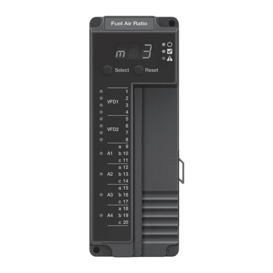
- Page 6 Table 1. LED Descriptions. LED Displays The SLATE system modules have three-character LED displays used for indicating the module number of the SLATE system. They also have three-position LED colors to indicate terminal states as shown in Table 2. Color...
- Page 7 3. After installation is complete, check out the product operation as provided in these instructions. 4. The SLATE module must be mounted in an electrical enclosure with adequate clearance for servicing, installation and removal of modules.
- Page 8 Wiring WARNING Electrical Shock Hazard. Can cause severe injury, death or equipment damage. 1. Disconnect the power supply before beginning installation to prevent electrical shock and equipment damage. More than one power supply disconnect can be involved. M35383 Fig. 2. Installing the Fuel Air Ratio Module on the Sub-Base Module.
- Page 9 Can cause severe injury, death, or property damage. Disconnect the power supply from the main disconnect before beginning installation to prevent electrical shock and equipment damage. More than one disconnect can be required. SLATE FUEL AIR RATIO MODULE ™ R8001C6001...
- Page 10 FUEL AIR MODULE VFD1 4 ACTUATORS 2 VFD (OR LOW V UNIVERSAL LOW VOLTAGE INPUT/OUTPUT) CELL VFD2 UNIVERSAL LOW VOLTAGE CELL RS-485 ACTUATOR 1 ACTUATOR 2 RS-485 ACTUATOR 3 RS-485 ACTUATOR 4 RS-485 M35284 Fig. 3. Wiring diagram for Fuel Air Ratio Module. 32-00006—03...
- Page 11 A2 - C (GND) A3 - A (RS485) A3 - B (RS485) A3 - C (GND) A4 - A (RS485) A4 - B (RS485) A4 - C (GND) Unused Unused Table 3. Terminal Ratings. SLATE FUEL AIR RATIO MODULE ™ R8001C6001...
- Page 12 Terminal Functions Typical Max Units T1 Voltage In Range 15.0 Rin=1MOhm Resolution - 2.43 - mV DC Null -25.0 25.0 mV DC Accuracy -25.0 25.0 mV DC Whichever is greater -1.0 Range 15.0 10KOhm load Resolution - - mV DC Null 100.0 - 100.0 mV DC...
- Page 13 135 °C to 150 °C Shielded cable required for reliable operation in noisy environment. NTC on terminal T4 is rated down to 0 °C. Temperatures refer to sense range. Table 5. Specifications Cell Complex Functions. SLATE FUEL AIR RATIO MODULE ™ R8001C6001...
- Page 14 Frequency / PWM Typical Max Units Functions PWM Out Amplitude 10.0 Low output state = 0V Frequency 100.0 - 1000.0 Hz Duty Cycle 98.0 0-100% output allowed Resolution Accuracy -0.5 - 10V amplitude Frequency In Amplitude 10.0 15.0 Range 1000.0 Hz...
- Page 15 Table 8. Recommended Wire Sizes and Part Numbers. Resistance to Temperature Conversion Tables Below are the lookup tables for various types of SLATE sensors. Linear interpolation is used for values that are between the points that are shown. 10K NTC...
- Page 16 298.598 158.116 358.318 148.295 429.982 138.912 619.174 121.345 891.610 105.213 1283.918 90.347 1848.843 76.605 2662.333 63.862 3833.760 52.015 5520.614 40.972 7949.685 30.653 11447.546 20.990 19781.359 7.594 34182.189 -4.636 59066.823 -15.846 102067.470 -26.159 176372.588 -35.678 304771.832 -44.491 12K NTC Ohms Degrees C 494.600 124.750 560.400...
- Page 17 20K NTC Ohms Degrees C 372.200 150.000 555.080 133.250 842.660 117.050 1301.180 101.450 2047.500 86.400 3284.380 71.900 5378.420 57.850 8996.680 44.250 15345.520 31.150 26744.880 18.500 47748.920 6.250 87148.340 -5.550 163394.900 -17.000 260844.260 -25.000 SLATE FUEL AIR RATIO MODULE ™ R8001C6001...
- Page 18 100 ohm RTD Ohms Degrees C 18.526 -200.250 50.064 -125.250 88.223 -30.250 132.801 84.750 174.010 194.750 213.822 304.750 250.520 409.750 280.962 499.750 1000 ohm RTD Ohms Degrees C 185.26 -200.250 500.64 -125.250 882.23 -30.250 1328.01 84.750 1740.10 194.750 2138.22 304.750 2505.20 409.750 2809.62...
- Page 19 1026.230 Type K thermocouple microVolts Degrees C -5000.000 -153.736 -4400.000 -129.609 -3600.000 -101.517 -2600.000 -70.403 -1200.000 -31.171 -700.000 17.529 6500.000 159.027 11300.000 278.023 17500.000 426.066 29000.000 696.902 34500.000 829.998 39500.000 954.713 41600.000 1008.307 SLATE FUEL AIR RATIO MODULE ™ R8001C6001...
- Page 20 Type T thermocouple microVolts Degrees C -5000.000 -166.012 -4200.000 -130.434 -3100.000 -89.867 -1600.000 -43.103 500.000 13.280 3100.000 74.769 6500.000 146.427 10900.000 230.361 16500.000 328.408 20800.000 399.315 Recommended Grounding Practices Use an Earth ground or a signal ground as described below. Earth ground (Base, Rectification Flame Amp Module, other modules optional) 1.
- Page 21 Be sure loads do not exceed the terminal ratings. Refer to the labels or terminal ratings in Table 3. The SLATE system must be mounted in an electrical enclosure. When mounting in an electrical enclosure, provide adequate clearance for servicing, installation and removal of SLATE modules.
- Page 22 32-00006—03...
- Page 23 SLATE FUEL AIR RATIO MODULE ™ R8001C6001...
- Page 24 32-00006-03 For more information and detailed instructions on the R8001C6001 and the entire SLATE system please refer to the SLATE User Guide located on our website at http://combustion.honeywell.com/SLATE Automation and Control Solutions Honeywell International Inc. ® U.S. Registered Trademark. 1985 Douglas Drive North ©...
Need help?
Do you have a question about the SLATE and is the answer not in the manual?
Questions and answers