Sign In
Upload
Manuals
Brands
YASKAWA Manuals
Engine
SGMPS
YASKAWA SGMPS Manuals
Manuals and User Guides for YASKAWA SGMPS. We have
11
YASKAWA SGMPS manuals available for free PDF download: User Manual, Instruction Manual
YASKAWA SGMPS User Manual (435 pages)
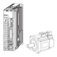
AC Servo Drives, Rotational Motor, Analog Voltage and Pulse Train Reference, SERVOPACK, Servomotors
Brand:
YASKAWA
| Category:
Servo Drives
| Size: 6 MB
Table of Contents
About this Manual
3
Notation Used in this Manual
4
Safety Information
5
Safety Precautions
6
Storage and Transportation
7
Installation
7
Operation
9
Maintenance and Inspection
9
Disposal Precautions
10
General Precautions
10
Warranty
11
Warranty Period
11
Warranty Scope
11
Limitations of Liability
11
Suitability for Use
12
Harmonized Standards
13
Safety Standards
14
Table of Contents
15
Σ-V Series Servopacks
22
Part Names
22
S-V Series Servopacks
22
SERVOPACK Ratings and Specifications
23
Ratings
23
Basic Specifications
25
Speed/Position/Torque Control
28
SERVOPACK Internal Block Diagrams
29
Single-Phase 100 V, SGDV-R70F01A, -R90F01A, -2R1F01A Models
29
Single-Phase 100 V, SGDV-2R8F01A Model
29
Single-Phase 200 V, SGDV-120A01A008000 Model
30
Three-Phase 200 V, SGDV-R70A01, -R90A01, -1R6A01 Models
30
Three-Phase 200 V, SGDV-2R8A01 Model
31
Three-Phase 200 V, SGDV-3R8A01A, -5R5A01A, -7R6A01A Models
31
Three-Phase 200 V, SGDV-120A01A Model
32
Three-Phase 200 V, SGDV-180A01A, -200A01A Models
32
Three-Phase 200 V, SGDV-330A01A Model
33
Three-Phase 200 V, SGDV-470A01A, -550A01A Models
33
Three-Phase 200 V SGDV-590A01A, -780A01A Models
34
Three-Phase 400 V, SGDV-1R9D01A, -3R5D01A, -5R4D01A Models
34
Three-Phase 400 V, SGDV-8R4D01A, -120D01A Models
35
Three-Phase 400 V, SGDV-170D01A Model
35
Three-Phase 400 V, SGDV-210D01A, -260D01A Models
36
Three-Phase 400 V, SGDV-280D01A, -370D01A Models
36
Examples of Servo System Configurations
37
Connecting to SGDV-F01A SERVOPACK
37
Connecting to SGDV-A01 SERVOPACK
38
Connecting to SGDV-Ooof01A SERVOPACK
38
Connecting to SGDV-D01A SERVOPACK
40
Connecting to SGDV-Oood01A SERVOPACK
40
SERVOPACK Model Designation
41
Servo Drive Maintenance and Inspection
42
SERVOPACK Inspection
42
Servopack's Parts Replacement Schedule
42
Servomotor Inspection
43
Chapter 2 Panel Operator
45
Overview
45
Names and Functions
45
Display Selection
45
Status Display
46
Utility Functions (Fn)
47
Parameters (Pn)
48
Parameter Classification
48
Notation for Parameters
48
Parameters (Pnooo)
48
Setting Parameters
49
Setting Parameters
51
Monitor Displays (Un)
52
Monitor Displays (Unooo)
52
Chapter 3 Wiring and Connection
54
Main Circuit Wiring
54
Main Circuit Terminals
54
Using a Standard Power Supply (Single-Phase 100 V, Three-Phase 200 V, or Three-Phase 400 V)
55
Using a Standard Power Supply (Sin- Gle-Phase 100 V, Three-Phase 200 V, or Three-Phase 400 V)
55
Wire Types
55
Single-Phase
56
Three-Phase
56
Typical Main Circuit Wiring Examples
57
Using the SERVOPACK with Single-Phase, 200 V Power Input
64
Parameter Setting
64
Using the SERVOPACK with a DC Power Input
67
Power-On Sequence
68
Using more than One SERVOPACK
72
Wiring Example
72
General Precautions for Wiring
73
I/O Signal Connections
74
I/O Signal (CN1) Names and Functions
74
Output Signals
75
Safety Function Signal (CN8) Names and Functions
76
Example of I/O Signal Connections in Speed Control
77
Example of I/O Signal Connections in Position Control
78
Example of I/O Signal Connections in Torque Control
79
I/O Signal Allocations
80
Input Signal Allocations
80
Output Signal Allocations
85
Checking Output Signals
88
Examples of Connection to Host Controller
89
Reference Input Circuit
89
Analog Input Circuit
89
Sequence Input Circuit
91
Sequence Output Circuit
93
Specifications
94
Encoder Connection
95
Encoder Signal (CN2) Names and Functions
95
Encoder Connection Examples
95
Incremental Encoder
95
Absolute Encoder
96
Connecting Regenerative Resistors
97
Setting Regenerative Resistor Capacity
99
Noise Control and Measures for Harmonic Suppression
100
Wiring for Noise Control
100
Noise Filter
101
Precautions on Connecting Noise Filter
102
Connecting a Reactor for Harmonic Suppression
103
Chapter 4 Trial Operation
105
Inspection and Checking before Trial Operation
105
Trial Operation for Servomotor Without Load
105
Trial Operation for Servomotor Without Load from Host Reference
106
Inspecting Connection and Status of Input Signals
108
Operation
108
Trial Operation in Speed Control
110
Trial Operation under Position Control from the Host Controller with the SERVOPACK Used for Speed Control
111
Trial Operation in Position Control
112
Trial Operation with the Servomotor Connected to the Machine
113
Trial Operation of Servomotor with Brakes
114
Test Without Motor Function
115
Motor Information
115
Motor Position and Speed Responses
116
Limitations
117
Operator Displays During Testing Without Motor
118
Control Method Selection
121
Basic Functions Settings
122
Servo on Signal
122
Signal Setting
122
Servomotor Rotation Direction
123
Overtravel
124
Holding Brakes
127
Stopping Servomotors after /S-ON Turned off or Alarm Occurrence
132
Instantaneous Power Interruption Settings
134
SEMI F47 Function (Torque Limit Function for Low DC Power Supply Voltage for Main Circuit)
135
SEMI F47 Function
135
Related Parameters
137
Setting Motor Overload Detection Level
138
Speed Control
140
Basic Settings for Speed Control
140
Signal Setting
140
Parameter Setting
141
Reference Offset Adjustment
141
Operating Procedure
142
Soft Start
144
Speed Reference Filter
144
Zero Clamp Function
145
Related Parameter
146
Encoder Output Pulses
147
Setting Encoder Output Pulse
148
Setting Speed Coincidence Signal
149
Position Control
150
Basic Settings for Position Control
151
Connection Example
151
Line Driver Output
152
Open-Collector Output
152
Clear Signal Setting
155
Reference Pulse Input Multiplication Switching Function
156
Input Signal Setting
156
Output Signal Setting
157
Electronic Gear
157
Electronic Gear Ratio
158
Electronic Gear Ratio Setting Examples
159
Smoothing
160
Related Parameters
160
Positioning Completed Signal
161
Positioning Near Signal
162
Reference Pulse Inhibit Function
163
Torque Control
164
Basic Settings for Torque Control
164
Signal Setting
164
Parameter Setting
165
Reference Offset Adjustment
165
Operating Procedure
166
Torque Reference Filter
168
Speed Limit in Torque Control
168
Speed Limit Setting
168
Internal Set Speed Control
170
Basic Settings for Speed Control with an Internal Set Speed
170
Example of Operating with Internal Set Speeds
172
Combination of Control Methods
173
Switching Internal Set Speed Control (Pn000.1 = 4, 5, or 6)
173
Switching Other than Internal Set Speed Control (Pn000.1 = 7, 8 or 9)
176
Switching Other than Internal Set Speed Control (Pn000.1 = a or B)
176
Limiting Torque
177
Internal Torque Limit
177
External Torque Limit
178
Input Signals
178
Torque Limiting Using an Analog Voltage Reference
179
Torque Limiting Using an External Torque Limit and Analog Voltage Reference
181
Checking Output Torque Limiting During Operation
183
Absolute Encoders
184
Connecting the Absolute Encoder
185
Absolute Data Request Signal (SEN)
187
Battery Replacement
188
Battery Replacement Procedure
189
Absolute Encoder Setup and Reinitialization
191
Absolute Data Reception Sequence
192
Multiturn Limit Setting
196
Multiturn Limit Disagreement Alarm (A.CC0)
197
Other Output Signals
198
Servo Alarm Output Signal (ALM) and Alarm Code Output Signals (ALO1, ALO2, and ALO3)
198
Warning Output Signal (/WARN)
199
Signal Specifications
199
Related Parameters
199
Rotation Detection Output Signal (/TGON)
200
Related Parameter
200
Servo Ready Output Signal (/S-RDY)
200
Safety Function
201
Hard Wire Base Block (HWBB) Function
201
Risk Assessment
201
Hard Wire Base Block (HWBB) State
202
Resetting the HWBB State
202
Error Detection in HWBB Signal
202
Connection Example and Specifications of Input Signals (HWBB Signals)
203
Servo Ready Output (/S-RDY)
204
Dynamic Brake
205
External Device Monitor (EDM1)
205
Application Example of Safety Functions
207
Failure Detection Method
207
Confirming Safety Functions
208
Safety Device Connections
209
Precautions for Safety Functions
210
Chapter 6 Adjustments
213
Type of Adjustments and Basic Adjustment Procedure
213
Adjustments
213
Basic Adjustment Procedure
215
Monitoring Operation During Adjustment
216
Related Parameters
218
Safety Precautions on Adjustment of Servo Gains
219
Torque Limit
219
Tuning-Less Function
222
Application Restrictions
222
Advertisement
YASKAWA SGMPS User Manual (400 pages)
AC ?-V Series
Brand:
YASKAWA
| Category:
Servo Drives
| Size: 15 MB
Table of Contents
About this Manual
3
Safety Precautions
6
Applicable Standards
11
Table of Contents
12
Chapter 1 Outline
19
Σ-V Series Servopacks
19
Part Names
19
SERVOPACK Ratings and Specifications
20
Ratings
20
Basic Specifications
21
Speed/Position/Torque Control Modes
23
SERVOPACK Internal Block Diagrams
24
Single-Phase 100 V, SGDV-R70F01A, -R90F01A, -2R1F01A Models
24
Single-Phase 100 V, SGDV-2R8F01A Model
24
Three-Phase 200 V, SGDV-R70A01A, -R90A01A, -1R6A01A Models
25
Three-Phase 200 V, SGDV-2R8A01A Model
25
Three-Phase 200 V, SGDV-3R8A01A, -5R5A01A, -7R6A01A Models
26
Three-Phase 200 V, SGDV-120A01A Model
26
Three-Phase 200 V, SGDV-180A01A, -200A01A Models
27
Three-Phase 200 V, SGDV-330A01A Model
27
Three-Phase 200 V, SGDV-470A01A, -550A01A Models
28
Three-Phase 200 V SGDV-590A01A, -780A01A Models
28
Three-Phase 400 V, SGDV-1R9D01A, -3R5D01A, -5R4D01A Models
29
Three-Phase 400 V, SGDV-8R4D01A, -120D01A Models
29
Three-Phase 400 V, SGDV-170D01A Model
30
Three-Phase 400 V, SGDV-210D01A, -260D01A Models
30
Three-Phase 400 V SGDV-280D01A, -370D01A Models
31
Examples of Servo System Configurations
32
Connecting to SGDV- F01A SERVOPACK
32
A01A Servopack
33
D01A Servopack
34
SERVOPACK Model Designation
35
Inspection and Maintenance
36
Chapter 2 Panel Operator
38
Panel Operator
38
Display Mode Selection
38
Status Display Mode
39
Utility Function Mode (Fn )
40
How to Read a Parameter Explanation
41
Explanation Method for Parameter Setting Type
41
Explanation Method for Function Selection Type
41
Explanation Method for Tuning Parameters
42
Parameter Setting Mode (Pn )
43
Parameter Setting Mode for Parameter Setting Type
43
Parameter Setting Mode for Function Selection Type
46
Monitor Mode (un )
47
Chapter 3 Wiring and Connection
49
Main Circuit Wiring
49
Names and Functions of Main Circuit Terminals
50
SERVOPACK Main Circuit Wire Size
51
Typical Main Circuit Wiring Examples
52
General Precautions for Wiring
56
Precautions When Using the SERVOPACK with a DC Power Input
57
Precautions When Using the SERVOPACK with Single-Phase, 200 V Power Input
59
Precautions When Using more than One SERVOPACK
62
I/O Signal Connections
63
I/O Signal (CN1) Names and Functions
63
I/O Signal Connector (CN1) Terminal Layout
65
Safety Function Signal (CN8) Names and Functions
66
Example of I/O Signal Connections in Speed Control
67
Example of I/O Signal Connections in Position Control
68
Example of I/O Signal Connections in Torque Control
69
I/O Signal Allocations
70
Input Signal Allocations
70
Output Signal Allocations
74
Examples of Connection to Host Controller
78
Reference Input Circuit
78
Sequence Input Circuit
80
Sequence Output Circuit
81
Examples of Encoder Connection
83
Connection Example of an Encoder
83
CN2 Encoder Connector Terminal Layout
84
Connecting Regenerative Resistors
85
Setting Regenerative Resistor Capacity
87
Noise Control and Measures for Harmonic Suppression
88
Wiring for Noise Control
88
Precautions on Connecting Noise Filter
90
Connecting AC/DC Reactor for Harmonic Suppression
92
Chapter 4 Trial Operation
94
Inspection and Checking before Trial Operation
94
Trial Operation for Servomotor Without Load
94
Trial Operation for Servomotor Without Load from Host Reference
95
Inspecting Connection and Status of Input Signal Circuits
97
Trial Operation in Speed Control
99
Trial Operation under Position Control from the Host with the SERVOPACK Used for Speed Control
100
Trial Operation in Position Control
101
Trial Operation with the Servomotor Connected to the Machine
102
Trial Operation of Servomotor with Brakes
103
Test Without Motor Function
104
Related Parameters
104
Limitations
104
Operating Procedure
106
Operator Display During Testing Without Motor
107
Chapter 5 Operation
108
Control Selection
110
Setting Common Basic Functions
111
Servo on Signal
111
Servomotor Rotation Direction
112
Overtravel
113
Holding Brakes
115
Stopping Servomotors after /S_ON Turned off or Alarm Occurrence
120
Instantaneous Power Interruption Settings
122
SEMI F47 Function (Torque Limit Function for Low Power Supply Voltage for Main Circuit)
123
Setting Motor Overload Detection Level
126
Operating Using Speed Control with Analog Voltage Reference
128
Basic Settings for Speed Control
128
Reference Offset Adjustment
130
Soft Start
132
Speed Reference Filter
133
Zero Clamp Function
134
Encoder Output Pulses
137
Encoder Output Pulse Setting
138
Encoder Output Pulses
138
Speed Coincidence Signal Setting
139
Operating Using Position Control with Pulse Train Reference
140
Basic Settings for Position Control Mode
140
Clear Signal
145
Electronic Gear
146
Smoothing
149
Positioning Completed Output Signal
150
Positioning Near Signal
151
Reference Pulse Inhibit Function
152
Operating Using Torque Control with Analog Voltage Reference
154
Basic Settings for Torque Control Mode
154
Reference Offset Adjustment
155
Torque Reference Filter
158
Speed Limit in Torque Control
158
Operating Using Speed Control with an Internal Set Speed
160
Basic Settings for Speed Control with an Internal Set Speed
160
Example of Operating with Internal Set Speed
162
Combination of Control Modes
163
Switching Internal Set Speed Control (Pn000.1 = 4, 5, or 6)
164
Switching Other than Internal Set Speed Control (Pn000.1 = 7, 8 or 9)
166
Switching Other than Internal Set Speed Control (Pn000.1 = a or B)
166
Limiting Torque
167
Internal Torque Limit
167
External Torque Limit
168
Torque Limiting Using an Analog Voltage Reference
169
Torque Limiting Using an External Torque Limit and Analog Voltage Reference
170
Checking Output Torque Limiting During Operation
171
Absolute Encoders
172
Encoder Resolutions
172
Standard Connection Diagram and Setting the Absolute Data Request Signal (SEN)
173
Absolute Encoder Data Backup
174
Battery Replacement
175
Absolute Encoder Setup
177
Absolute Encoder Reception Sequence
178
Multiturn Limit Setting
181
Multiturn Limit Disagreement Alarm (A.CC0)
182
Other Output Signals
183
Servo Alarm Output Signal (ALM) and Alarm Code Output Signals (ALO1, ALO2, and ALO3)
183
Warning Output Signal (/WARN)
184
Rotation Detection Output Signal (/TGON)
185
Servo Ready Output Signal (/S-RDY)
185
Safety Function
186
Hard Wire Base Block (HWBB) Function
186
External Device Monitor (EDM1)
190
Application Example of Safety Functions
192
Confirming Safety Functions
193
Precautions for Safety Functions
194
Chapter 6 Adjustments
195
Adjustments and Basic Adjustment Procedure
197
Adjustments
197
Basic Adjustment Procedure
199
Monitoring Analog Signals
200
Safety Precautions on Adjustment of Servo Gains
202
Tuning-Less Function
205
Tuning-Less Levels Setting (Fn200) Procedure
208
Advanced Autotuning (Fn201)
211
Advanced Autotuning
211
Advanced Autotuning Procedure
214
Related Parameters
220
Advanced Autotuning by Reference (Fn202)
221
Advanced Autotuning by Reference
221
Advanced Autotuning by Reference Procedure
224
Related Parameters
228
One-Parameter Tuning (Fn203)
229
One-Parameter Tuning
229
One-Parameter Tuning Procedure
231
One-Parameter Tuning Example
237
Related Parameters
238
Anti-Resonance Control Adjustment Function (Fn204)
239
Anti-Resonance Control Adjustment Function
239
Anti-Resonance Control Adjustment Function Operating Procedure
240
Related Parameters
244
Vibration Suppression Function (Fn205)
245
Vibration Suppression Function
245
Vibration Suppression Function Operating Procedure
246
Related Parameters
249
Additional Adjustment Function
250
Switching Gain Settings
250
Friction Compensation
255
Friction Compensation
256
Current Control Mode Selection
257
Current Gain Level Setting
257
Speed Detection Method Selection
257
Compatible Adjustment Function
258
Feedforward Reference
258
Torque Feedforward
259
Speed Feedforward
260
Proportional Control Operation (Proportional Operation Reference)
261
Using the Mode Switch (P/PI Switching)
262
Torque Reference Filter
267
Position Integral Time Constant
268
YASKAWA SGMPS User Manual (378 pages)
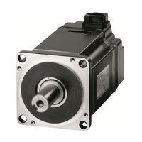
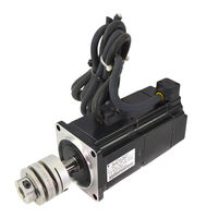
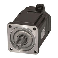
Rotational Motor MECHATROLINK-II Communications Reference
Brand:
YASKAWA
| Category:
Servo Drives
| Size: 5 MB
Table of Contents
About this Manual
3
Safety Precautions
7
Warranty
12
Harmonized Standards
14
Table of Contents
16
Chapter 1 Outline
22
Σ-V Series Servopacks
22
Part Names
22
SERVOPACK Ratings and Specifications
23
Ratings
23
Basic Specifications
25
MECHATROLINK-II Function Specifications
28
SERVOPACK Internal Block Diagrams
29
Single-Phase 100 V, SGDV-R70F11A, -R90F11A, -2R1F11A Models
29
Single-Phase 100 V, SGDV-2R8F11A Model
29
Single-Phase 200 V, SGDV-120A11A008000 Model
30
Three-Phase 200 V, SGDV-R70A11, -R90A11, -1R6A11 Models
30
Three-Phase 200 V, SGDV-2R8A11 Model
31
Three-Phase 200 V, SGDV-3R8A11A, -5R5A11A, -7R6A11A Models
31
Three-Phase 200 V, SGDV-120A11A Model
32
Three-Phase 200 V, SGDV-180A11A, -200A11A Models
32
Three-Phase 200 V, SGDV-330A11A Model
33
Three-Phase 200 V, SGDV-470A11A, -550A11A Models
33
Three-Phase 200 V SGDV-590A11A, -780A11A Models
34
Three-Phase 400 V, SGDV-1R9D11A, -3R5D11A, -5R4D11A Models
34
Three-Phase 400 V, SGDV-8R4D11A, -120D11A Models
35
Three-Phase 400 V, SGDV-170D11A Model
35
Three-Phase 400 V, SGDV-210D11A, -260D11A Models
36
Three-Phase 400 V, SGDV-280D11A, -370D11A Models
36
Examples of Servo System Configurations
37
Connecting to SGDV-F11A SERVOPACK
37
Connecting to SGDV-A11 SERVOPACK
38
Connecting to SGDV-D11A SERVOPACK
40
SERVOPACK Model Designation
41
Servo Drive Maintenance and Inspection
42
SERVOPACK Inspection
42
Servopack's Parts Replacement Schedule
42
Servomotor Inspection
43
Chapter 2 Panel Display and Operation of Digital Operator
45
Panel Display
45
Status Display
45
Alarm and Warning Display
45
Hard Wire Base Block Display
45
Overtravel Display
45
Operation of Digital Operator
46
Utility Functions (Fn)
46
Parameters (Pn)
47
Parameter Classification
47
Notation for Parameters
47
Setting Parameters
48
Monitor Displays (Un)
50
Chapter 3 Wiring and Connection
52
Main Circuit Wiring
52
Main Circuit Terminals
52
Using a Standard Power Supply (Single-Phase 100 V, Three-Phase 200 V, or Three-Phase 400 V)
53
Using a Standard Power Supply (Sin- Gle-Phase 100 V, Three-Phase 200 V, or Three-Phase 400 V)
53
Using the SERVOPACK with Single-Phase, 200 V Power Input
61
Using the SERVOPACK with a DC Power Input
64
Using more than One SERVOPACK
66
General Precautions for Wiring
67
I/O Signal Connections
68
I/O Signal (CN1) Names and Functions
68
Safety Function Signal (CN8) Names and Functions
69
Example of I/O Signal Connections
70
I/O Signal Allocations
71
Input Signal Allocations
71
Output Signal Allocations
73
Examples of Connection to Host Controller
74
Sequence Input Circuit
74
Sequence Output Circuit
75
Wiring MECHATROLINK-II Communications
77
Encoder Connection
78
Encoder Signal (CN2) Names and Functions
78
Encoder Connection Examples
78
Connecting Regenerative Resistors
80
Setting Regenerative Resistor Capacity
82
Noise Control and Measures for Harmonic Suppression
83
Wiring for Noise Control
83
Precautions on Connecting Noise Filter
85
Connecting a Reactor for Harmonic Suppression
86
Chapter 4 Operation
87
MECHATROLINK-II Communications Settings
89
Setting the Communications Specifications
89
Setting the Station Address
90
MECHATROLINK-II Commands
90
Basic Functions Settings
91
Servomotor Rotation Direction
91
Overtravel
92
Software Limit Settings
95
Holding Brakes
96
Stopping Servomotors after SV_OFF Command or Alarm Occurrence
101
Instantaneous Power Interruption Settings
103
SEMI F47 Function
104
Setting Motor Overload Detection Level
107
Trial Operation
109
Inspection and Checking before Trial Operation
109
Trial Operation Via MECHATROLINK-II
110
Electronic Gear
111
Encoder Output Pulses
113
Setting Encoder Output Pulse
114
Test Without Motor Function
115
Motor Information
115
Motor Position and Speed Responses
116
Limitations
117
Digital Operator Displays During Testing Without Motor
118
Limiting Torque
119
Internal Torque Limit
119
External Torque Limit
120
Checking Output Torque Limiting During Operation
121
Absolute Encoders
122
Connecting the Absolute Encoder
123
Absolute Data Request (SENS on Command)
125
Battery Replacement
126
Absolute Encoder Setup and Reinitialization
128
Absolute Data Reception Sequence
129
Multiturn Limit Setting
134
Multiturn Limit Disagreement Alarm (A.CC0)
135
Absolute Encoder Origin Offset
136
Other Output Signals
137
Servo Alarm Output Signal (ALM)
137
Warning Output Signal (/WARN)
137
Rotation Detection Output Signal (/TGON)
138
Servo Ready Output Signal (/S-RDY)
138
Speed Coincidence Output Signal (/V-CMP)
139
Positioning Completed Output Signal (/COIN)
140
Positioning Near Output Signal (/NEAR)
141
Speed Limit Detection Signal (/VLT)
142
Safety Function
144
Hard Wire Base Block (HWBB) Function
144
External Device Monitor (EDM1)
150
Application Example of Safety Functions
152
Confirming Safety Functions
153
Safety Device Connections
154
Precautions for Safety Functions
155
Chapter 5 Adjustments
158
Type of Adjustments and Basic Adjustment Procedure
158
Adjustments
158
Basic Adjustment Procedure
159
Monitoring Operation During Adjustment
160
Safety Precautions on Adjustment of Servo Gains
163
Tuning-Less Function
166
Tuning-Less Levels Setting (Fn200) Procedure
169
Related Parameters
171
Advanced Autotuning (Fn201)
172
Advanced Autotuning
172
Advanced Autotuning Procedure
175
Related Parameters
181
Advanced Autotuning by Reference (Fn202)
182
Advanced Autotuning by Reference
182
Advanced Autotuning by Reference Procedure
185
Related Parameters
189
One-Parameter Tuning (Fn203)
190
One-Parameter Tuning
190
One-Parameter Tuning Procedure
192
One-Parameter Tuning Example
198
Related Parameters
200
Anti-Resonance Control Adjustment Function (Fn204)
201
Anti-Resonance Control Adjustment Function
201
Anti-Resonance Control Adjustment Function Operating Procedure
202
Related Parameters
206
Vibration Suppression Function (Fn205)
207
Vibration Suppression Function
207
Vibration Suppression Function Operating Procedure
208
Related Parameters
211
Additional Adjustment Function
212
Switching Gain Settings
212
Manual Adjustment of Friction Compensation
216
Current Control Mode Selection Function
218
Current Gain Level Setting
218
Speed Detection Method Selection
218
Backlash Compensation Function
219
Compatible Adjustment Function
225
Feedforward Reference
225
Mode Switch (P/PI Switching)
226
Torque Reference Filter
228
Position Integral
230
Advertisement
YASKAWA SGMPS User Manual (177 pages)
?-III series servomotor
Brand:
YASKAWA
| Category:
Engine
| Size: 7 MB
Table of Contents
About this Manual
3
Safety Information
5
General Precautions
11
Maintenance and Inspection
11
Table of Contents
12
1 Outline
16
Checking Products
17
Check Items
17
Servomotors
17
Servopacks
18
Product Part Names
19
Servomotors
19
Servopacks
20
Examples of Servo System Configurations
21
Applicable Standards
26
North American Safety Standards (UL, CSA)
26
CE Marking
26
2 Selections
27
Servomotor Model Designations
28
Model SGMAS/SGMPS/SGMSS
28
Model SGMCS
30
SERVOPACK Model Designations
31
Σ-III Series Servopacks and Applicable Servomotors
32
Selecting Cables
33
Cables for SGMAS and SGMPS Servomotor
33
Cables for SGMSS Servomotor
41
Cables for SGMCS Servomotor
46
Selecting Peripheral Devices
50
Special Options
50
Molded-Case Circuit Breaker and Fuse Capacity
51
Noise Filters
52
Regenerative Resistors
53
3 SERVOPACK Specifications and Dimensional Drawings
55
SERVOPACK Ratings and Specifications
55
SERVOPACK Installation
57
SERVOPACK Internal Block Diagrams
59
Single-Phase 100 V, 50 W to 400 W Models
59
Single-Phase 200 V, 50 W to 400W Models
60
Three-Phase 200 V, 1.0 Kw Models
61
Single-Phase 200 V, 750 W Model
62
Three-Phase 200 V, 1.5 Kw to 3.0 Kw Models
63
SERVOPACK Power Losses
64
Inertia
65
Overload Characteristics
65
SERVOPACK Overload Characteristics and Load Moment of
65
Load Moment of Inertia
66
Starting and Stopping Time
66
Classification Table
70
Dimensional Drawings of SERVOPACK Model SGDS-
70
Dimensional Drawings of SERVOPACK Model SGDS- 72
70
Single-Phase 100 V/200 V, 50 W/100 W/200 W
70
Single-Phase 100 V, 400 W
71
Single-Phase 200 V, 400 W
71
Single-Phase 200 V, 750 W, and Three-Phase 200 V, 1.0 Kw
72
Three-Phase 200 V, 1.5 Kw
72
Three-Phase 200 V, 2.0 Kw / 3.0 Kw
73
4 Specifications and Dimensional Drawings of Cables and Peripheral Devices
74
SERVOPACK Main Circuit Wire Size
75
Connectors for Main Circuit, Control Power Supply, and Servomotor Cable
77
Spring Type (Standard)
77
Crimp Type (Option)
78
CN1 Cables for I/O Signals
79
Connector Type and Cable Size
79
Standard Cables
79
Cables for Analog Monitor
81
Cables for Connecting Personal Computers
81
Digital Operator
81
Peripheral Devices
81
Connector Terminal Block Converter Unit
82
Brake Power Supply Unit
83
External Regenerative Resistor
84
Absolute Encoder Battery
86
Molded-Case Circuit Breaker (MCCB)
87
Noise Filter
88
Magnetic Contactor
91
Surge Protector
93
AC/DC Reactors for Harmonic Suppression
94
YASKAWA SGMPS User Manual (113 pages)
AC Servo Drives. E-V series. Rotational Motor
Brand:
YASKAWA
| Category:
Servo Drives
| Size: 8 MB
Table of Contents
About this Manual
3
Safety Precautions
8
Warranty
15
Applicable Standards
17
Table of Contents
18
1 Overview of Setup
20
2 Installation
22
Installation Environment and Applicable Standards
23
Servomotor Installation Environment
23
SERVOPACK Installation Environment
24
Installation Conditions for Applicable Standards
25
Servomotor Installation
26
Orientation
26
Installation Standards
26
Connecting Servomotor to Machine
27
Protective Structure
28
Other Precautions
29
SERVOPACK Installation
30
Orientation
30
Installation Standards
32
EMC Installation Conditions
34
SGDV- (Analog Pulse Model)
34
SGDV- (M-II Model)
42
SGDV- (M-III Model)
50
SGDV- E1A (Command Option Attachable Type)
58
Other Precautions
58
3 Wiring and Connection
59
Precautions for Wiring
60
System Configuration Diagram
61
Connecting to SGDV
61
Servopack
61
SERVOPACK (Analog Pulse Model)
61
Connecting to SGDV
62
Connecting to SGDV
65
Servo
65
Servopack
65
SERVOPACK (M-II Model)
65
SERVOPACK (M-III Model)
70
Connecting to SGDV- E1A SERVOPACK
74
Connecting to SGDV- E1A SERVOPACK (Command Option Attachable Type)
74
Main Circuit Wiring
77
Names and Functions of Main Circuit Terminals
77
SERVOPACK Main Circuit Wire Size
78
Typical Main Circuit Wiring Examples
82
Wiring the Main Circuit Terminal Connector (Spring Type)
86
Wiring the Main Circuit Terminal Connector
86
Connecting Regenerative Resistors
89
Connecting Regenerative Resistor
89
4 Safety Function
92
Outline
93
Hard Wire Base Block (HWBB) Function
94
Safety Function Signal (CN8) Names and Functions
95
Precautions When Not Using the Safety Function
95
Connecting a Safety Function Device
96
YASKAWA SGMPS User Manual (62 pages)
AC Servo Drives
Brand:
YASKAWA
| Category:
Servo Drives
| Size: 0 MB
Table of Contents
About this Manual
3
Safety Precautions
8
Warranty
15
Table of Contents
22
Chapter 1 Outline
24
Σ-V-FT-Series FT008
24
SERVOPACK Ratings and Specifications
24
Ratings
24
Basic Specifications
26
Control Specifications
29
SERVOPACK Model Designation
30
Introductions to Functions
32
Differences from an Absolute Data Reception Sequence with a Standard Σ-V-Series SERVOPACK
32
Parameter Set Values and Settings
33
Application Examples
34
When Using a Rotational Servomotor
34
When Using Fully-Closed Loop Control or When Using a Linear Servomotor
36
Setting the Specification for Absolute Encoder Setup (Initialization)
38
Description of Settings
38
Setting the Specification for Absolute Encoder Setup
38
(Initialization) (Fn008)
38
Absolute Encoder Setup (Initialization)
39
Setting the Specification for Absolute Data Reception Sequence
43
Absolute Data Reception Sequence
43
Setting the Absolute Data Request Signal
46
Description of Settings
46
Connection to Host Controller
46
PSO Serial Data
48
Data Specifications
48
Output Terminals
50
Encoder Ready (/E-RDY) Signal
51
Managing Positions at the Host Controller
52
Chapter 3 List of Monitor Displays and Parameters for the Σ-V-FT-Series FT008
55
Additional Monitor Displays
56
Special Parameters
57
Precaution When Copying Parameters
59
Index
60
YASKAWA SGMPS User Manual (61 pages)
AC Servo Drive MECHATROLINK-III Communications Reference
Brand:
YASKAWA
| Category:
Servo Drives
| Size: 0 MB
Table of Contents
About this Manual
3
Safety Precautions
9
Warranty
16
Table of Contents
23
Chapter 1 Outline
26
Σ-V-FT-Series FT003
26
SERVOPACK Ratings and Specifications
26
Ratings
26
Basic Specifications
28
MECHATROLINK-III Function Specifications
30
SERVOPACK Model Designation
31
Overview
34
Application Restrictions
35
Functional Restrictions
35
Sigmawin+ Engineering Tool
35
Input Signal Connection
36
Cable Connection
36
Recommended Pressure Sensor Amplifier Specifications
36
Pressure Feedback Operation Patterns
37
Changing from Torque Control to Pressure Feedback Control
38
Mode 1
38
Mode 2
39
Control Block Diagram
40
Setup Procedures
41
Flowchart
41
Parameter Settings
42
Gain Adjustment
45
Chapter 3 Monitoring
49
Alarm Displays
52
Alarms Unique to the Σ-V-FT-Series FT003
52
Troubleshooting of Alarms
52
Warning Displays
53
Warnings Unique to the Σ-V-FT-Series FT003
53
Troubleshooting of Warnings
53
Chapter 5 Parameters Specifically Related to the Σ-V-FT-Series FT003
55
Special Parameters
56
Changed Parameters
58
Precaution When Copying Parameters
58
YASKAWA SGMPS User Manual (59 pages)
AC Servo Drive Rotational Motor, MECHATROLINK-III Communications Reference
Brand:
YASKAWA
| Category:
Servo Drives
| Size: 0 MB
Table of Contents
About this Manual
3
Safety Precautions
8
Warranty
13
Table of Contents
19
Chapter 1 Outline
22
Σ-V-FT-Series FT005
22
SERVOPACK Ratings and Specifications
22
Ratings
22
Basic Specifications
24
MECHATROLINK-III Function Specifications
26
SERVOPACK Model Designation
27
Overview
30
Basic Specifications
30
Basic Operation
31
Operating Procedure
32
Flow of Operation
32
Setting the Rotational Coordinate System
32
Setting the Multiturn Limit
33
Setting the Absolute Encoder Origin Offset
34
Setting the Moving Method of the Rotational Coordinate System
35
Servo Command Specification Methods
37
Monitoring
42
Overview
44
Basic Specifications
44
Basic Operation
45
Forward Travel
45
Changing to Reverse from Forward Travel
45
Changing to Reverse from Forward Travel During Output of Trigger Signal at Pre-Set Position: Composite Signal Output
46
Stopping on the Trigger Position
46
Operating Procedure
47
Flow of Operation
47
Trigger Signal Allocations
48
Setting Trigger Positions
50
Setting the Output Signal Widths
51
Chapter 4 List of Σ-V-FT-Series FT005 Parameters
53
Special Parameters
54
Precaution When Copying Parameters
56
Index
57
YASKAWA SGMPS User Manual (53 pages)
AC Servo Drives
Brand:
YASKAWA
| Category:
Servo Drives
| Size: 0 MB
Table of Contents
About this Manual
3
Safety Precautions
8
Warranty
13
Table of Contents
19
Chapter 1 Outline
22
Σ-V-FT-Series FT001
22
SERVOPACK Ratings and Specifications
23
Ratings
23
Basic Specifications
24
Control Specifications
26
SERVOPACK Model Designation
27
Chapter 2 Adjustments
30
Type of Adjustments and Basic Adjustment Procedure
30
Adjustments
30
Basic Adjustment Procedure
32
Monitoring Operation During Adjustment
33
Safety Precautions on Adjustment of Servo Gains
36
Suppression Method for Continuous Vibration
39
Vibration Suppression with Notch Filters
39
Notch Filter Settings
40
Notch Filter Adjustment Procedure
41
Related Parameters
41
Suppression Method for Residual Vibration During Positioning
43
Vibration Suppression with the Vibration Suppression 2 Function
43
Vibration Suppression by Switching the Gain
44
Index
51
YASKAWA SGMPS User Manual (47 pages)
AC Servo Drives MECHATROLINK-III Communications Reference
Brand:
YASKAWA
| Category:
Servo Drives
| Size: 0 MB
Table of Contents
About this Manual
3
Safety Precautions
8
Warranty
15
Table of Contents
22
Chapter 1 Outline
24
Σ-V-FT-Series FT006
24
SERVOPACK Ratings and Specifications
24
Ratings
24
Basic Specifications
26
MECHATROLINK-III Function Specifications
28
SERVOPACK Model Designation
29
Overview
32
Basic Specifications
32
Basic Operation
33
Forward Travel
33
Changing to Reverse from Forward Travel
33
Changing to Reverse from Forward Travel During Output of Trigger Signal at Pre-Set Position: Composite Signal Output
34
Stopping on the Trigger Position
34
Operating Procedure
35
Flow of Operation
35
Trigger Signal Allocations
36
Setting Trigger Positions
38
Setting the Output Signal Widths
39
Chapter 3 List of Σ-V-FT-Series FT006 Parameters
41
Special Parameters
42
Precaution When Copying Parameters
44
Index
45
YASKAWA SGMPS Instruction Manual (43 pages)
AC Servo Drives MECHATROLINK-III Communications Reference
Brand:
YASKAWA
| Category:
Servo Drives
| Size: 0 MB
Table of Contents
About this Manual
3
Safety Precautions
8
Warranty
15
Table of Contents
22
Chapter 1 Outline
24
Σ-V-EX-Series EX002
24
SERVOPACK Ratings and Specifications
24
Ratings
24
Basic Specifications
26
1.2.3 MECHATROLINK-III Function Specifications
29
SERVOPACK Model Designation
30
Overview
32
Restrictions
32
Control Mode Restrictions
32
Functional Restrictions
32
Application Method
33
Adjustment
34
Adjustment Procedure
34
2.4.2 Adjustment Example
35
Gain Switching
36
Gain Combinations for Switching
36
Method to Switch the Gain
36
Settings at Low Speeds
36
Chapter 3 Parameters Specifically Related to the Σ-V-EX-Series EX002
37
Special Parameters
38
Changed Parameters
39
Precaution When Copying Parameters
40
Index
41
Advertisement
Related Products
YASKAWA SGDH
YASKAWA SGMDH
YASKAWA SGMAS
YASKAWA SGMSS
YASKAWA SGMCS
YASKAWA S-II Series
YASKAWA SGDH SERVOPACK
YASKAWA SGMP Series
YASKAWA SGMP-01A
YASKAWA SGMP-08A
YASKAWA Categories
Controller
DC Drives
Servo Drives
Robotics
Control Unit
More YASKAWA Manuals
Login
Sign In
OR
Sign in with Facebook
Sign in with Google
Upload manual
Upload from disk
Upload from URL