Sign In
Upload
Manuals
Brands
YASKAWA Manuals
Controller
GA700
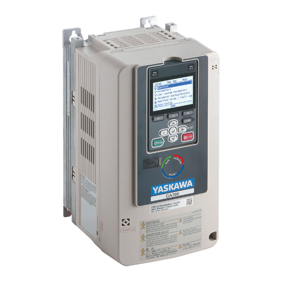
YASKAWA GA700 Manuals
Manuals and User Guides for YASKAWA GA700. We have
7
YASKAWA GA700 manuals available for free PDF download: Technical Manual, Installation Manual, Initial Steps
YASKAWA GA700, GA800, CH700, CR700, LA700, ES700 Manual
Brand:
YASKAWA
| Category:
CD/CDR Drive
| Size: 4 MB
Table of Contents
Overview
Receiving
Install the Attachment
Necessary Tools
Drive Mounting Dimensions and Panel Cut-out Dimensions
Drive External Dimensions
Panel Cut-Out Dimensions
Kit Models and Installation Procedure
Use the External Heatsink Installation Kit
Use the Mounting Bracket Supplied with the Drive
Gasket and Sealant
General Safety
Supplemental Safety Information
Section Safety
Documents / Resources
References
Advertisement
YASKAWA GA700 Technical Manual (1053 pages)
Brand:
YASKAWA
| Category:
DC Drives
| Size: 83 MB
Table of Contents
Table of Contents
3
Preface and General Precautions
13
Receiving
14
Glossary
14
About Registered Trademarks
14
Using the Product Safely
15
Supplemental Safety Information
15
General Safety
15
Warning Label Content and Location
17
Warranty Information
18
Warranty and Exclusion of Liability
18
1 Receiving
19
Section Safety
20
Model Number and Nameplate Check
21
Nameplate
21
How to Read Model Numbers
21
Features and Advantages of Control Methods
26
2 Mechanical & Electrical Installation
31
General Safety
32
Installation Environment
35
Installation Position and Distance
36
Moving the Drive
38
Using the Hanging Brackets to Move the Drive
38
Instructions on Drive Suspension
38
Drive Watt Loss
40
Remove and Reattach the Keypad
44
Remove the Keypad
44
Reattach the Keypad
44
Install the Keypad to a Control Panel or Another Device
45
Operate the Keypad Apart from the Drive
45
Connect the Keypad from a Remote Location
45
Removing/Reattaching Covers
50
Removing/Reattaching the Cover Using Procedure a
50
Removing/Reattaching the Cover Using Procedure B
51
Change the Drive Enclosure Type
55
Attach the Protective Cover (Procedure A)
55
Attach the Protective Cover (Procedure B)
56
Attach the Protective Cover (Procedure C)
58
Attach the Protective Cover (Procedure D)
61
Attach the Protective Cover (Procedure E)
63
Attach the Protective Cover (Procedure F)
65
Installation Methods
68
Electrical Installation
73
Standard Connection Diagram
73
Main Circuit Wiring
76
Motor and Main Circuit Connections
76
Configuration of Main Circuit Terminal Block
76
Main Circuit Terminal Functions
81
Wire Selection
82
Main Circuit Terminal and Motor Wiring
94
Protection of Main Circuit Terminals
97
Main Circuit Terminal Block Wiring Procedure
98
Wiring the Main Circuit Terminal Block Using Procedure a
98
Wiring the Main Circuit Terminal Block Using Procedure B
101
Control Circuit Wiring
104
Control Circuit Connection Diagram
104
Control Circuit Terminal Block Functions
105
Control Circuit Terminal Configuration
108
Wiring the Control Circuit Terminal
110
Switches and Jumpers on the Terminal Board
112
Control I/O Connections
113
Pulse Train Output
113
Set Sinking Mode/Sourcing Mode
114
Set Input Signals for MFAI Terminals A1 to A3
114
Set MFAI Terminal A3 to PTC Input
115
Set Output Signals for MFAO Terminals FM, am
115
Switch on Termination Resistor for Memobus/Modbus Communications
116
Connect the Drive to a PC
117
External Interlock
118
Braking Resistor Installation
119
Install a Braking Resistor: ERF-Type
119
Install a Braking Resistor Unit: LKEB-Type
119
Install a Braking Unit Connection: CDBR-Type
120
Connect Braking Units in Parallel
120
Dynamic Braking Option Overload Protection
121
Drive Wiring Protection
122
(Rcm/Rcd)
122
Install a Residual Current Monitoring/Detection (RCM/RCD)
122
Dynamic Braking Option, Motor Protection
123
Install an Electromagnetic Contactor (MC) at the Input Side of the Drive
123
Install a Thermal Overload Relay on the Drive Output
123
Improve the Power Factor
125
Connect an AC Reactor or a DC Reactor
125
Prevent Switching Surge
126
Decrease Noise
127
Connect a Noise Filter to the Input Side (Primary Side)
127
Connect a Noise Filter to the Output Side (Secondary Side)
127
Protect the Drive During Failures
129
Factory-Recommended Branch Circuit Protection
129
Wiring Checklist
133
Motor Application Precautions
135
Precautions for Existing Standard Motors
135
Precautions for PM Motors
136
Precautions for Specialized Motors
136
Notes on the Power Transmission Mechanism
137
3 Startup Procedure and Test Run
139
Safety Precautions
140
Component Names and Functions
141
LCD Display
143
Indicator Leds and Drive Status
144
Keypad Mode and Menu Displays
145
LED Status Ring
147
Start-Up Procedures
149
Flowchart A: Connect and Run the Motor with Minimum Setting Changes
149
Sub-Chart A-1: Induction Motor Auto-Tuning and Test Run Procedure
150
Sub-Chart A-2: PM Motor Auto-Tuning and Test Run Procedure
150
Subchart A-3: EZ Open Loop Vector Control Test Run Procedure
152
Items to Check before Starting up the Drive
153
Check before Energizing the Drive
153
Check after Energizing the Drive
153
Make the Initial Settings
154
Keypad Operation
155
Use the HOME Screen
155
Show the Standard Monitor
156
Set Custom Monitors
157
Show Custom Monitors
157
Set the Monitors to Show as a Bar Graph
158
Show Monitors as Bar Graphs
159
Set the Monitors to Show as Analog Gauges
160
Display Monitors as an Analog Gauge
161
Set Monitoring Items to be Shown as a Trend Plot
162
Show Monitor Items as a Trend Plot
165
Change Parameter Settings
166
Examine User Custom Parameters
168
Save a Backup of Parameters
169
Write Backed-Up Parameters to the Drive
170
Verify Keypad Parameters and Drive Parameters
171
Delete Parameters Backed up to the Keypad
172
Check Modified Parameters
173
Restore Modified Parameters to Defaults
174
Show Fault History
176
Auto-Tuning the Drive
176
Set the Keypad Language Display
179
Set the Date and Time
179
Set Parameters Using the Setup Wizard
181
Disable the Initial Setup Screen
183
Start Data Logging
183
Set Data to Log
184
Set Backlight to Automatically Turn off
186
Show Information about the Drive
188
Write Automatically Backed-Up Parameters to the Drive
189
Automatic Parameter Settings Optimized for Specific Applications
190
Presets)
190
Automatic Parameter Settings Optimized for Specific Applications (Application Presets)
190
Auto-Tuning
192
Auto-Tuning for Induction Motors
192
Auto-Tuning for PM Motors
193
EZ Tuning
196
Control Tuning
197
Precautions before Auto-Tuning
199
Test Run
202
Load Test Run
202
Do a No-Load Test Run
202
Actual-Load Test Run
202
Do an Actual-Load Test Run
203
Fine Tuning During Test Runs (Adjust the Control Function)
204
V/F Control and Closed Loop V/F Control
204
Open Loop Vector Control Method
205
Closed Loop Vector Control Method
208
Advanced Open Loop Vector Control Method
209
Fine-Tuning Open Loop Vector Control for PM Motors
211
Advanced Open Loop Vector Control Method for PM
212
Closed Loop Vector Control Method for PM
213
EZ Open Loop Vector Control Method
214
Test Run Checklist
215
4 Standards Compliance
219
General Safety
220
European Standards
222
EU Declaration of Conformity
223
CE Low Voltage Directive Compliance
228
EMC Directive
245
UL Standards
256
Area of Use
256
Wire the Main Circuit Terminal Block
256
Low Voltage Wiring for Control Circuit Terminals
276
Drive Motor Overload and Overheat Protection
276
China Rohs Compliance
282
Information on Hazardous Substances in this Product
282
对应中国Rohs指令
283
本产品中含有有害物质的信息
283
Safe Disable Input
284
Safe Disable Specifications
284
Notes
285
Using the Safe Disable Function
285
5 Network Communications
289
Safety Precautions
290
Field Bus Network Support
291
Memobus/Modbus Communications
292
Configure Master/Slave
292
Communication Specifications
292
Communication with the PLC
292
Memobus/Modbus Drive Operations
294
Communications Timing
294
Message Format
295
Examples of Messages for Commands/Responses
297
Enter Command
302
Self-Diagnostics
303
Communications Data Table
303
Error Codes
325
6 Troubleshooting
327
General Safety
328
Types of Faults, Minor Faults, Alarms, and Errors
330
List of Fault, Minor Fault, Alarm, and Error Codes
331
Faults
337
Minor Faults/Alarms
361
Parameter Setting Errors
374
Auto-Tuning Errors
381
Backup Function Operating Mode Display and Errors
386
Diagnosing and Resetting Faults
388
Fault and Power Loss Occur at the same Time
388
Fault Occurs Without Power Loss
388
Fault Reset
388
Troubleshooting Without Fault Display
389
The Parameter Settings will Not Change
389
The Motor Does Not Rotate after Entering Run Command
389
The Motor Rotates in the Opposite Direction from the Run Command
390
The Motor Rotates in Only One Direction
391
The Motor Is too Hot
391
The Correct Auto-Tuning Mode Is Not Available
391
The Motor Stalls During Acceleration or Accel/Decel Time Is too Long
392
Command
393
The Motor Speed Is Not Stable When Using a PM Motor
393
There Is too Much Motor Oscillation and the Rotation Is Irregular
393
Deceleration Takes Longer than Expected When Dynamic Braking Is Enabled
394
The Load Falls When a Brake Is Applied
394
Energized
394
Residual Current Monitoring/Detection (RCM/RCD) Trips During Run
395
Motor Rotation Causes Unexpected Audible Noise from Connected Machinery
395
Motor Rotation Causes Oscillation or Hunting
395
PID Output Fault
395
The Starting Torque Is Not Sufficient
396
The Motor Rotates after the Drive Output Is Shut off
396
The Output Frequency Is Lower than the Frequency Reference
396
The Motor Is Making an Audible Noise
396
The Motor will Not Restart after a Loss of Power
396
YASKAWA GA700 Technical Manual (1021 pages)
AC Drive for Industrial Applications
Brand:
YASKAWA
| Category:
Industrial Equipment
| Size: 81 MB
Table of Contents
Table of Contents
3
Preface and General Precautions
13
Receiving
14
Glossary
14
About Registered Trademarks
14
Using the Product Safely
16
Explanation of Signal Words
16
Section Safety
16
Warning Label Content and Location
18
Warranty Information
19
Exclusion of Liability
19
Receiving
21
Section Safety
22
Verifying the Drive Model and Nameplate
23
Nameplate
23
How to Read the Model Number
23
Features and Advantages of Control Methods
27
Mechanical Installation
31
Section Safety
32
Installation Environment
34
Installation Position and Clearances
35
Install Single Drive
35
Install Drives Side-By-Side
35
Moving the Drive
37
Using the Hanging Brackets to Move the Drive
37
Instructions on Drive Suspension
37
Drive Watt Loss
39
Class
39
Class
40
Remove and Reattach the Keypad
43
Remove the Keypad
43
Reattach the Keypad
43
Install the Keypad in a Control Panel or Another Device
44
Operate the Keypad from a Remote Location
44
Connect the Keypad from a Remote Location
44
Removing/Reattaching Covers
49
Removing/Reattaching the Cover Using Procedure a
49
Removing/Reattaching the Cover Using Procedure B
50
Change the Drive Enclosure Type
54
Installation Methods
55
Standard Installation
55
External Heatsink
55
Electrical Installation
61
Section Safety
62
Electrical Installation
65
Standard Connection Diagram
65
Main Circuit Wiring
68
Motor and Main Circuit Connections
68
Configuration of Main Circuit Terminal Block
68
Main Circuit Terminal Functions
73
Wire Selection
74
Main Circuit Terminal and Motor Wiring
84
Protection of Main Circuit Terminals
87
Main Circuit Terminal Block Wiring Procedure
88
Wire the Main Circuit Terminal Block with Procedure a
88
Wire the Main Circuit Terminal Block with Procedure B
91
Control Circuit Wiring
94
Control Circuit Connection Diagram
94
Control Circuit Terminal Block Functions
95
Control Circuit Terminal Configuration
100
Wiring the Control Circuit Terminal
101
Switches and Jumpers on the Terminal Board
103
Control I/O Connections
104
Set Sinking Mode/Sourcing Mode
104
Pulse Train Output
104
Set Input Signals for MFAI Terminals A1 to A3
105
Set MFAI Terminal A3 to PTC Input
106
Set Output Signals for MFAO Terminals FM, am
106
Switch on Termination Resistor for Memobus/Modbus Communications
107
Connect the Drive to a PC
108
External Interlock
109
Drive Ready
109
Interlock Circuit Example
109
Braking Resistor Installation
110
Install a Braking Resistor: ERF-Type
110
Install a Braking Resistor Unit: LKEB-Type
110
Install a Braking Unit Connection: CDBR-Type
111
Connect Braking Units in Parallel
116
Dynamic Braking Option Overload Protection
117
Drive Wiring Protection
118
Installing a Residual Current Monitoring/Detection (RCM/RCD)
118
(Rcm/Rcd)
118
Dynamic Braking Option, Motor Protection
119
Install an Electromagnetic Contactor (MC) at the Input Side of the Drive
119
Installing a Thermal Overload Relay on the Drive Output
119
Improve the Power Factor
121
Connect an AC Reactor or a DC Reactor
121
Prevent Switching Surge
122
Decrease Noise
123
Connect a Noise Filter to the Input Side (Primary Side)
123
Connect a Noise Filter to the Output Side (Secondary Side)
123
Protect the Drive During Failures
125
Factory-Recommended Branch Circuit Protection for UL Listing
125
Wiring Checklist
128
Motor Application Precautions
130
Precautions for Existing Standard Motors
130
Precaution When You Use IE3 Premium Efficiency Motors
131
Precautions for PM Motors
131
Precautions for Specialized Motors
131
Notes on the Power Transmission Mechanism
132
Startup Procedure and Test Run
133
Section Safety
134
Keypad Components and Functions
135
LCD Display
136
Indicator Leds and Drive Status
137
Keypad Mode and Menu Displays
139
LED Status Ring
141
Start-Up Procedures
143
Flowchart A: Connect and Run the Motor with Minimum Setting Changes
143
Sub-Chart A-1: Induction Motor Auto-Tuning and Test Run Procedure
144
Sub-Chart A-2: PM Motor Auto-Tuning and Test Run Procedure
145
Subchart A-3: EZ Open Loop Vector Control Test Run Procedure
146
Items to Check before Starting up the Drive
147
Check before Energizing the Drive
147
Check after You Energize the Drive
147
Make the Initial Settings
147
Keypad Operation
149
Home Screen Display Selection
149
Show the Monitor
150
Set Custom Monitors
151
Show Custom Monitors
152
Set the Monitors to Show as a Bar Graph
152
Show Monitors as Bar Graphs
154
Set the Monitors to Show as Analog Gauges
154
Display Monitors as an Analog Gauge
155
Set Monitoring Items to be Shown as a Trend Plot
156
Show Monitor Items as a Trend Plot
159
Change Parameter Setting Values
160
Examine User Custom Parameters
162
Save a Backup of Parameters
163
Write Backed-Up Parameters to the Drive
164
Verify Keypad Parameters and Drive Parameters
165
Delete Parameters Backed up to the Keypad
166
Check Modified Parameters
167
Restore Modified Parameters to Defaults
168
Show Fault History
170
Auto-Tuning the Drive
170
Set the Keypad Language Display
172
Set the Date and Time
173
Set Parameters Using the Setup Wizard
175
Disable the Initial Setup Screen
177
Start Data Logging
177
Configuring the Data Log Content
178
Set Backlight to Automatically Turn off
180
Show Information about the Drive
182
Write Automatically Backed-Up Parameters to the Drive
183
Automatic Parameter Settings Optimized for Specific Applications
184
Presets)
184
Automatic Parameter Settings Optimized for Specific Applications (Application Presets)
184
Auto-Tuning
186
Auto-Tuning for Induction Motors
186
Auto-Tuning for Motor Parameters for PM Motor
187
Auto-Tuning in EZ Open Loop Vector Control Method
189
Control Tuning
190
Precautions before Auto-Tuning
191
Test Run
195
Load Test Run
195
Do a No-Load Test Run
195
Actual-Load Test Run
195
Do an Actual-Load Test Run
196
Fine Tuning During Test Runs (Adjust the Control Function)
197
V/F Control and Closed Loop V/F Control
197
Open Loop Vector Control Method
198
Closed Loop Vector Control Method
200
Advanced Open Loop Vector Control Method
200
Open Loop Vector Control for PM Motors
201
Advanced Open Loop Vector Control Method for PM Motors
202
Closed Loop Vector Control Method for PM
203
EZ Open Loop Vector Control Method
203
Test Run Checklist
204
Standards Compliance
207
Section Safety
208
European Standards
210
EU Declaration of Conformity
211
CE Low Voltage Directive Compliance
216
EMC Directive
231
UL Standards
241
Area of Use
241
Wire the Main Circuit Terminal Block
241
UL Standards Compliance for DC Power Supply Input
258
Low Voltage Wiring for Control Circuit Terminals
259
Drive Motor Overload and Overheat Protection
260
China Rohs Compliance
266
Information on Hazardous Substances in this Product
266
对应中国Rohs指令
267
本产品中含有有害物质的信息
267
Safe Disable Input
268
Safe Disable Specifications
268
Notes
269
Using the Safe Disable Function
269
Network Communications
275
Section Safety
276
Field Bus Network Support
277
Memobus/Modbus Communications
278
Configure Master/Slave
278
Communication Specifications
278
Communication with the PLC
278
Memobus/Modbus Drive Operations
280
Communications Timing
280
Message Format
281
Examples of Messages for Commands/Responses
283
Enter Command
287
Self-Diagnostics
288
Communications Data Table
289
Error Codes
309
Troubleshooting
311
Section Safety
312
Types of Faults, Minor Faults, Alarms, and Errors
314
List of Fault, Minor Fault, Alarm, and Error Codes
315
Fault
320
Minor Faults/Alarms
349
Parameter Setting Errors
360
Auto-Tuning Errors
366
Backup Function Operating Mode Display and Errors
371
Diagnosing and Resetting Faults
372
Fault and Power Loss Occur at the same Time
372
Fault Occurs Without Power Loss
372
Fault Reset
372
Troubleshooting Without Fault Display
373
Typical Problems
373
The Parameter Settings will Not Change
373
The Motor Does Not Rotate after Entering Run Command
374
The Motor Rotates in the Opposite Direction from the Run Command
375
The Motor Rotates in Only One Direction
375
The Motor Is too Hot
375
The Correct Auto-Tuning Mode Is Not Available
376
The Motor Stalls During Acceleration or Accel/Decel Time Is too Long
376
Command
377
The Motor Speed Is Not Stable When Using a PM Motor
377
There Is too Much Motor Oscillation and the Rotation Is Irregular
377
Deceleration Takes Longer than Expected When Dynamic Braking Is Enabled
377
The Load Falls When a Brake Is Applied
378
Drive
378
Residual Current Monitoring/Detection (RCM/RCD) Trips During Run
378
Motor Rotation Causes Unexpected Audible Noise from Connected Machinery
378
Motor Rotation Causes Oscillation or Hunting
379
PID Output Fault
379
The Starting Torque Is Not Sufficient
379
The Motor Rotates after the Drive Output Is Shut off
379
The Output Frequency Is Lower than the Frequency Reference
379
The Motor Is Making an Audible Noise
380
The Motor will Not Restart after a Loss of Power
380
Periodic Inspection and Maintenance
381
Section Safety
382
Advertisement
YASKAWA GA700 Technical Manual (936 pages)
High Performance Type; 200 V class: 0.4 to 110 kW; 400 V class: 0.4 to 355 kW
Brand:
YASKAWA
| Category:
Controller
| Size: 29 MB
Table of Contents
Table of Contents
3
Preface and General Precautions
13
Receiving
14
About Terms and Abbreviations in this Document
14
About Registered Trademarks
14
I.1 Receiving
14
Using the Product Safely
15
Supplemental Safety Information
15
Safety Precautions
15
Warning Label Content and Locations
17
Warranty Information
18
Warranty Period
18
Warranty Scope
18
Warranty and Exclusion of Liability
18
I.3 Warranty Information
18
1 Receiving
19
Section Safety
20
Receiving
21
Nameplate
21
How to Read Model Numbers
21
2 Mechanical & Electrical Installation
25
Safety Precautions
26
Installation Environment
29
Installation Orientation and Spacing
30
Transport
32
Using the Hanging Brackets to Move the Drive
32
Drive Watt Loss
33
Remove or Install the Keypad
36
Remove the Keypad
36
Reattach the Keypad
36
Install the Keypad on the Control Panel or Other Devices
37
Operate the Keypad Apart from the Drive
37
Install Keypad Apart from Drive
37
Removing/Reattaching the Cover
42
Removing/Reattaching the Cover Using Procedure a
42
Change the Drive's Enclosure Type
44
Attach the Protective Cover (Procedure A)
44
Installation Procedure
46
Electrical Installation
50
Standard Connection Diagram
50
Main Circuit Wiring
53
Configuration of Main Circuit Terminal Block
53
Main Circuit Terminal Functions
54
Main Circuit Wire Gauges and Tightening Torques
55
Main Circuit Terminal and Motor Wiring
64
Protection of Main Circuit Terminals
67
Wiring Procedure for the Main Circuit Terminal Block
68
Wiring the Main Circuit Terminal Block Using Procedure a
68
Control Circuit Wiring
71
Control Circuit Connection Diagram
71
Control Circuit Terminal Block Functions
72
Control Circuit Terminal Configuration
75
Wiring the Control Circuit Terminal
77
Switches and Jumpers on the Terminal Board
78
Control I/O Connections
80
Pulse Train Output
80
Setting Sink Mode/Source Mode
81
Selection of Input Signals for Terminals A1 to A3 of Multi-Function Analog Input
81
Select Input Signal for Terminal A3 of Multi-Function Analog Input
82
Output
82
Switch on Termination Resistor for Memobus/Modbus Communications
83
External Interlock
84
Install Braking Resistor
85
Installing a Braking Resistor: ERF Type
85
Installing a Braking Resistor Unit : LKEB Type
85
Installing a Braking Unit Connection: CDBR Type
86
Connect Braking Units in Parallel
86
Dynamic Braking Option Overload Protection
87
Protect Drive Wiring
88
(Elcb)
88
Installing a Ground Fault Circuit Interrupter
88
Dynamic Braking Option, Motor Protection
89
Installing an Electromagnetic Contactor (MC) at Input Side of Drive
89
Installing a Thermal Overload Relay on the Drive Output
89
Improving the Power Factor
91
Connecting an AC Reactor or DC Reactor
91
Preventing the Passage of Switching Surge
92
Reducing Noise
93
Connecting a Noise Filter to Input Side (Primary Side)
93
Connecting a Noise Filter to (Secondary Side)
93
Protect Drive at Failure
95
Factory Recommended Branch Circuit Protection
95
Wiring Checklist
99
Motor Application Precautions
101
Use with Existing Standard Motors
101
Use with PM Motors
102
Precautions Concerning Use of Specialized Motors
102
Notes on Power Transmission Mechanism
103
3 Initial Setup Trialrun
105
Safety Precautions
106
Keypad
107
LCD Display
109
LED Indications of the Keypad
110
Keypad Modes and Menus
111
LED Status Ring
113
Start-Up Procedures
115
Flowchart a (Connect Motor and Run It with Minimal Setting Changes)
115
Sub-Chart A1 (Induction Motor Auto-Tuning and Test Run Procedure)
116
Sub-Chart A-2 (PM Motor Auto-Tuning and Test Run Procedure)
117
Subchart A-3 (EZ Open Loop Vector Control Test Run Procedure)
119
Items to Check before Starting up Drive
120
Check before Powering up Drive
120
Check after Powering up Drive
120
Perform the Initial Settings
121
Keypad Operation
122
Use the HOME Screen
122
Show the Monitor
123
Set Monitoring Favorites
124
Show Monitoring Favorites
124
Set Monitor to be Displayed as Bar Graph
125
Display Monitor as Bar Graph
126
Set Monitor to be Displayed as Analog Meter
127
Show Monitor as Analog Meter
128
Change Parameter Setting Values
129
Checking Commonly Used Parameters
130
Saving a Backup of Parameters
131
Writing Backed-Up Parameters to the Drive
132
Verify Keypad Parameters and Drive Parameters
133
Checking Modified Parameters
134
Restoring Default Settings for Modified Parameters
136
Display Fault History
137
Perform Auto-Tuning
138
Select Language of Display for Keypad
140
Set the Date and Time
141
Use Setup Wizard to Set Parameters
143
Disable the Start-Up Screen
144
Start Data Logging
145
Set Data to Log
146
Set Backlight to be Automatically off
148
Display the Drive Information
149
Automatic Parameter Settings Optimized for Specific Applications
151
Auto-Tuning
153
Auto-Tuning for Induction Motors
153
Auto-Tuning for PM Motors
154
EZ Tuning
156
ASR and Inertia Tuning
157
Precautions to Note before Auto-Tuning
158
Test Run
161
No-Load Test Run
161
Perform a No-Load Test Run
161
Actual-Load Test Run
161
Perform an Actual-Load Test Run
162
Fine Tuning During Test Runs (Adjustment of Control Functionality)
163
V/F Control and Closed Loop V/F Control
163
Open Loop Vector Control Method
164
Closed Loop Vector Control Method
167
Advanced Open Loop Vector Control Method
168
Open Loop Vector Control Method for PM
169
Advanced Open Loop Vector Control Method for PM
171
Closed Loop Vector Control Method for PM
171
EZ Open Loop Vector Control Method
172
Test Run Checklist
173
4 Standards Compliance
177
Safety Precautions
178
European Standards
180
CE Low Voltage Directive Compliance
180
EMC Directive
195
UL Standards
203
Area of Use
203
Main Circuit Terminal Wiring
203
Low Voltage Wiring for Control Circuit Terminals
217
Drive Motor Overload and Overheat Protection
218
Safe Disable Input
224
Specification
224
Notes
225
Using the Safe Disable Function
225
5 Network Communications
229
Safety Precautions
230
Field Bus Network Support
231
Memobus/Modbus Communications
232
Configure Master/Slave
232
Communication Specifications
232
Communication with PLC
232
Drive Operations by Memobus/Modbus
234
Communications Timing
234
Message Format
235
Examples of Messages for Commands/Responses
237
Enter Command
238
Self-Diagnostics
239
Communications Data Table
240
Error Code
261
6 Troubleshooting
263
Safety Precautions
264
Types of Faults, Minor Faults, Alarms, and Errors
266
List of Fault, Minor Fault, Alarm, and Error Codes
267
Fault
273
Minor Faults/Alarms
296
Parameter Setting Errors
309
Auto-Tuning Errors
315
Backup Function Operating Mode Display and Errors
320
Diagnosing and Resetting Faults
322
Fault Occurs Simultaneously with Power Loss
322
If the Drive Still Has Power after a Fault Occurs
322
Fault Reset
322
Troubleshooting Without Fault Display
323
Cannot Change Parameter Settings
323
Motor Does Not Rotate after Entering Run Command
323
Motor Rotates in the Opposite Direction from the Run Command
325
Motor Rotates in One Direction Only
325
Motor Is too Hot
325
Drive Does Not Allow Selection of the Desired Auto-Tuning Mode
326
Motor Stalls During Acceleration or Accel/Decel Time Is too Long
326
Drive Frequency Reference Differs from the Controller Frequency Reference
327
Command
327
Unstable Motor Speed When Using PM Motor
327
Excessive Motor Oscillation and Erratic Rotation
328
Deceleration Takes Longer than Expected with Dynamic Braking Enabled
328
Load Falls When Brake Is Applied
328
Noise from Drive or Motor Cables When the Drive Is Powered on
329
Earth Leakage Circuit Breaker (ELCB) Trips During Run
329
Unexpected Noise from Connected Machinery Occurs When Motor Rotates
329
Oscillation or Hunting Occurs When Motor Rotates
329
PID Output Fault
330
Insufficient Starting Torque
330
Motor Rotates after the Drive Output Is Shut off
330
Output Frequency Is Not as High as Frequency Reference
330
Sound from Motor
331
Motor Does Not Restart after Power Loss
331
YASKAWA GA700 Installation Manual (186 pages)
IP55/UL Type 12 Heatsink External Mounting
Brand:
YASKAWA
| Category:
Servo Drives
| Size: 42 MB
Table of Contents
Table of Contents
3
English
9
Overview
9
Applicable Documentation
9
Safety
9
Explanation of Signal Words
9
General Safety Instructions
9
Warning Label Content and Location
11
Receiving
11
How to Read the Model Number
12
Installation Environment
13
Install the Gasket
14
Installation
15
Installation Procedure
15
Install the Drive (Procedure A)
15
Install the Drive (Procedure B)
16
Install the Drive (Procedure C)
17
Install the Drive (Procedure D)
18
Install the Drive (Procedure E)
19
Replace Cooling Fans and Circulation Fans
20
Replace Gasket
20
Common Drive Specifications
21
Drive Derating
24
Carrier Frequency Settings and Rated Current Values
24
Derating Depending on Ambient Temperature
24
L8-12: Ambient Temperature Setting
24
L8-35: Installation Method Selection
25
Side-By-Side Mounting
25
Altitude Derating
25
Deutsch
25
Übersicht
25
Geltende Dokumentation
26
Sicherheit
26
Erläuterung der Signalwörter
26
Allgemeine Sicherheitshinweise
26
Inhalt und Position von Warnetiketten
28
Liefereingang
29
Interpretation von Modellnummern
30
Installationsumgebung
31
Anbringen der Dichtung
32
IP55/UL Typ 12-Frequenzumrichter mit Externem Kühlkörper - Ausschnittsmaße und
33
Installation
33
Vorgehensweise für die Installation
33
Installation des Frequenzumrichters (Vorgehensweise A)
33
Installation des Frequenzumrichters (Vorgehensweise B)
34
Installation des Frequenzumrichters (Vorgehensweise C)
35
Installation des Frequenzumrichters (Vorgehensweise D)
36
Installation des Frequenzumrichters (Vorgehensweise E)
37
Ersetzen von Lüftern und Umwälzlüftern
38
Austauschen der Dichtung
38
Allgemeine Spezifikationen der Frequenzumrichter
39
Leistungsreduzierung
42
Taktfrequenzeinstellungen und Nennstromwerte
42
Leistungsreduzierung in Abhängigkeit von der Umgebungstemperatur
42
L8-12: Umgebungstemperatur Einstellung
43
L8-35: Auswahl der Installationsmethode
43
Leistungsreduzierung nach Höhe
44
Français
44
Vue D'ensemble
44
Documentation Applicable
44
Sécurité
44
Explication des Mots des Signaux
44
Instructions Générales de Sécurité
44
Contenu et Emplacement de L'étiquette D'avertissement
47
Réception
47
Comment Lire le Numéro de Modèle
48
Environnement D'installation
49
Positionnez le Joint
50
Découpe et Installation
51
Procédure D'installation
51
Installer le Variateur (Procédure A)
51
Installer le Variateur (Procédure B)
52
Installer le Variateur (Procédure C)
53
Installer le Variateur (Procédure D)
54
Installer le Variateur (Procédure E)
55
Remplacer les Ventilateurs de Refroidissement et les Ventilateurs de Circulation
56
Remplacer le Joint D'étanchéité
56
Spécifications Communes des Variateurs
57
Réduction de la Valeur Nominale du Variateur
60
Réglages de la Fréquence Porteuse et Valeurs du Courant Nominal
60
Réduction de la Valeur Nominale en Fonction de la Température Ambiante
60
L8-12: Réglage Température Ambiante
61
L8-35: Sélection Méthode D'installation
61
Réduction de la Valeur Nominale en Fonction de L'altitude
62
Italiano
62
Panoramica
62
Documentazione Applicabile
62
Sicurezza
62
Descrizione Dei Segnali DI Avvertimento
62
Istruzioni Generali DI Sicurezza
62
Contenuto Dell'etichetta DI Avvertenza E Posizione
64
Ricezione
65
Interpretazione del Numero DI Modello
66
Ambiente DI Installazione
67
Installazione Della Guarnizione
68
Installazione
69
Procedura DI Installazione
69
Installazione Dell'inverter (Procedura A)
69
Installazione Dell'inverter (Procedura B)
70
Installazione Dell'inverter (Procedura C)
71
Installazione Dell'inverter (Procedura D)
72
Installazione Dell'inverter (Procedura E)
73
Sostituzione Delle Ventole DI Raffreddamento E Delle Ventole DI Circolazione
74
Sostituzione Della Guarnizione
74
Specifiche Comuni Dell'inverter
75
Riduzione Inverter
78
Impostazioni Frequenza Portante E Valori Corrente Nominale
78
Riduzione in Funzione Della Temperatura Ambiente
78
L8-12: Impostazione Temp. Ambiente
79
L8-35: Selez. Metodo Installazione
79
Riduzione Altitudine
80
Español
80
Vista General
80
Documentación Aplicable
80
Seguridad
80
Explicación de Los Términos Indicativos
80
Instrucciones de Seguridad Generales
80
Contenido y Ubicación del Rótulo de Advertencia
82
Recepción
83
Cómo Leer el Número de Modelo
84
Lugar de Instalación
85
Instalación de la Junta
86
Externa del Disipador
87
Procedimiento para la Instalación
87
Instalación del Variador (Procedimiento A)
87
Instalación del Variador (Procedimiento B)
88
Instalación del Variador (Procedimiento C)
89
Instalación del Variador (Procedimiento D)
90
Instalación del Variador (Procedimiento E)
91
Sustitución de Ventiladores de Refrigeración y de Circulación
92
Sustitución de la Junta
92
YASKAWA GA700 Initial Steps (33 pages)
High Performance Type
Brand:
YASKAWA
| Category:
Controller
| Size: 7 MB
Table of Contents
General Information
2
Qualifications for the Intended User
2
Explanation of Signal Words
2
General Safety Instructions
2
Intended Use
4
Warranty and Exclusion of Liability
4
Moving the Drive
4
Keypad Mode and Menu Displays
8
LED Status Ring
10
Start-Up Procedure
11
Mechanical Installation
12
Installation Position and Distance
12
Single Drive Installation
12
Installation Environment
13
Removing the Covers
14
Remove the Front Cover
14
Remove the Terminal Cover
15
Electrical Installation
18
Standard Connection Diagram
18
Drive Start-Up
22
Setup Wizard
22
Auto Tuning
23
Change Parameter Settings
24
Drive Duty Modes
26
Drive Parameters
26
Faults and Alarms
29
Fault Reset Procedure
29
Disposal Instructions
31
YASKAWA GA700 Installation Manual (28 pages)
AC Drive
Brand:
YASKAWA
| Category:
CD/CDR Drive
| Size: 4 MB
Table of Contents
Table of Contents
3
1 Receiving
4
Applicable Documentation
4
Glossary
4
2 General Safety
4
Supplemental Safety Information
4
Section Safety
5
3 Overview
5
Compatible Products
5
4 Receiving
6
Option Package Contents
6
5 Install the Attachment
6
Necessary Tools
6
Drive Mounting Dimensions and Panel Cut-Out Dimensions
7
Drive External Dimensions
9
Panel Cut-Out Dimensions
12
Kit Models and Installation Procedure
14
Use the External Heatsink Installation Kit (Procedure A)
16
Use the Mounting Bracket Supplied with the Drive (Procedure B)
18
Use the Mounting Bracket Supplied with the Drive (Procedure C)
22
Gasket and Sealant
24
Revision History
26
Advertisement
Related Products
YASKAWA GPD515C
YASKAWA GA500 series
YASKAWA GA800 Series
YASKAWA GA800 600 V Drive
YASKAWA MEMOCON GL120
YASKAWA MEMOCON GL130
YASKAWA G7 Series
YASKAWA GA700 GA700 Series
YASKAWA GA70C4296BBA
YASKAWA GA80U2004
YASKAWA Categories
Controller
DC Drives
Servo Drives
Robotics
Control Unit
More YASKAWA Manuals
Login
Sign In
OR
Sign in with Facebook
Sign in with Google
Upload manual
Upload from disk
Upload from URL