Sign In
Upload
Manuals
Brands
Teledyne Manuals
Measuring Instruments
T200
Teledyne T200 Manuals
Manuals and User Guides for Teledyne T200. We have
4
Teledyne T200 manuals available for free PDF download: Operation Manual, User Manual, Training Manual
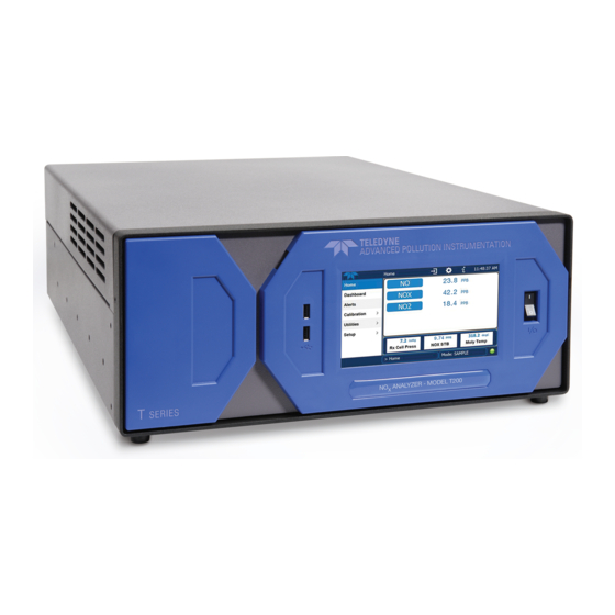
Teledyne T200 Operation Manual (452 pages)
Nitrogen Oxide Analyzer
Brand:
Teledyne
| Category:
Measuring Instruments
| Size: 9 MB
Table of Contents
Notice of Copyright
3
Safety Messages
5
Warranty
7
Terms and Conditions
7
About this Manual
9
Revision History
11
Table of Contents
13
List of Tables
22
General Information
25
Introduction
27
T200 Overview
27
Specifications and Approvals
29
Specifications
29
Table 2-1: T200 Basic Unit Specifications
29
EPA Equivalency Designation
30
Table 2-2: Software Settings for EPA Equivalence
30
CE Mark Compliance
31
Emissions Compliance
31
Safety Compliance
31
Getting Started
33
Front Panel
33
Figure 3-1: Front Panel Layout
33
Figure 3-2: Display Screen and Touch Control
34
Figure 3-3: Display/Touch Control Screen Mapped to Menu Charts
35
Rear Panel
36
Figure 3-4: Rear Panel Layout - Base Unit
36
Analyzer Layout
38
Figure 3-5: Internal Layout - Top View with IZS Option
38
Figure 3-6: Pneumatic Diagram - Basic T200
39
Unpacking the T200 Analyzer
40
Shock Hazard
40
Ventilation Clearance
42
Electrical Connections
42
Power Connection
42
Table 3-3: Ventilation Clearance
42
Analog Inputs (Option) Connections
44
Analog Output Connections
44
Figure 3-7: Analog in Connector
44
Figure 3-8: Analog Output Connector
45
Table 3-5: Analog Output Pin Outs
45
Connecting the Status Outputs
46
Figure 3-9: Status Output Connector
46
Table 3-6: Status Output Pin Assignments
46
Connecting the Control Inputs
47
Figure 3-10: Energizing the T200 Control Inputs
47
Table 3-7: Control Input Pin Assignments
47
Connecting the Serial Ports
48
Connecting to a LAN or the Internet
48
Connecting to a Personal Computer (PC)
48
Connecting to a Multidrop Network
48
Pnenumatic Connections
49
About Zero Air and Calibration Gas
49
Zero Air
49
Calibration (Span) Gas
49
Table 3-8: NIST-Srm's Available for Traceability of no
50
Span Gas for Multipoint Calibration
51
Basic Pneumatic Setup for the T200 Analyzer
52
Figure 3-11: Gas Line Connections from Calibrator - Basic T200 Configuration
52
Figure 3-12: Gas Line Connections from Bottled Span Gas - Basic T200 Configuration
52
Initial Operation
54
Start up
54
Warning Messages
55
Table 3-9: Possible Warning Messages at Start-Up
56
Functional Check
57
Initial Calibration of the T200 Analyzer
58
Interferents for Nox, no and NO2 Measurements
58
Initial Calibration Procedure for T200 Analyzers Without Options
58
Verifying the T200 Reporting Range Settings
59
Verify the Expected no and no Span Gas Concentration
60
Initial Zero/Span Calibration Procedure
61
Frequently Asked Questions and Glossary
63
Faq's
63
Glossary
65
Non-Gas Related Optional Hardware and Software
69
Optional Pumps (OPT 11A, OPT 11B, OPT 12A, OPT 12B & OPT 12C)
69
Rack Mount Kits (OPT 20A, OPT 20B, OPT 21 & OPT 23)
69
Carrying Strap/Handle (OPT 29)
70
Current Loop Analog Outputs (Opt 41)
70
Converting Current Loop Analog Outputs to Standard Voltage Outputs
71
Figure 5-1: Current Loop Option Installed
71
Spare Parts Kits
72
T200 Expendables Kit (OPT 42A)
72
Zero Air Scrubber Zero Air Maintenance Kit (OPT 43)
72
Communication Options
72
Serial Communications Cables (OPT 60A, 60B, 60C, & 60D)
72
Table 5-1: Contents of Zero Air Scrubber Maintenance Kit
72
Concentration Alarm Relay (Option 61)
73
Figure 5-2: Concentration Alarm Relay
73
Multidrop (OPT 62)
74
Special Features
74
Maintenance Mode Switch
74
Second Language Switch
74
Dilution Ratio Option
75
Gas Inlet and Calibration Valve Options
77
Table 6-1: List of T200 Calibration Gas Options
77
Ambient Zero/Ambient Span Valves (OPT 50A)
78
Figure 6-1: Rear Panel Layout with Z/S Valve Options (OPT 50A)
78
Internal Pneumatics (OPT 50A)
79
Figure 6-2: Pneumatic Diagram with Z/S Valves OPT 50A
79
Table 6-2: Zero/Span Valve Operating States OPT 50A
79
Pneumatic Setup (OPT 50A)
80
Figure 6-3: Gas Line Connections for T200 with Z/S Valves Option (OPT 50A)
80
Ambient Zero/Pressurized Span Valves (Opt 50B)
81
Figure 6-4: Rear Panel Layout with Pressurized Span Inlet OPT 50B
81
Internal Pneumatics (OPT 50B)
82
Figure 6-5: Pneumatic Diagram with Pressurized Span Inlet OPT 50B Installed
82
Table 6-3: Valve Operating States OPT 50B Installed
82
Pneumatic Setup (OPT 50B)
83
Figure 6-6: Gas Line Connections for T200 with OPT 50B
83
Internal Span Source - IZS (OPT 50G)
84
Span Gas Generation
84
Figure 6-7: Rear Panel Layout with Internal Span Gas Generator OPT 50G Installed
84
Nitric Acid and the Chemistry of no Permeation Tubes
85
Internal Pneumatics (OPT 50G)
86
Figure 6-8: Pneumatic Diagram with the Internal Span Gas Generator (OPT 50G)
86
Table 6-4: Internal Span Gas Generator Valve Operating States OPT 50G
86
Replacement Permeation Tubes (OPT 52B & OPT 52G)
87
Ammonia Removal Sample Conditioner (OPT 86A)
87
Figure 6-9: Pneumatics Diagram for Sample Conditioner OPT 86A
87
Table 6-5: Available Permeation Source Options
87
Zero Air Scrubber (Opt 86C), for Z/S Valves
88
Figure 6-10: Pneumatic Diagram for External Zero Air Scrubber with Z/S Valve Option
88
Basic Operation of the T200 Analyzer
91
Overview of Operating Modes
91
Front Panel Display
91
Sample Mode
92
Test Functions
92
Table 7-1: Analyzer Operating Modes
92
Figure 7-2: Viewing T200 Test Functions
93
Table 7-2: Test Functions Defined
94
Display Parameter
94
Warning Message Display
95
Table 7-3: Warning Messages Defined
95
Calibration Mode
96
SETUP Mode
97
Table 7-4: Primary Setup Mode Features and Functions
97
Table 7-5: Secondary Setup Mode Features and Functions
97
SETUP CFG: Configuration Information
98
SETUP PASS: Enabling/Disabling Passwords
99
Table 7-6: Password Levels
99
SETUP CLK: Setting the T200 Analyzer's Internal Clock
101
Setting the Internal Clock's Time and Day
101
Adjusting the Internal Clock's Speed
102
SETUP RNGE: Analog Output Reporting Range Configuration
103
T200 Physical Ranges
103
T200 Analog Output Reporting Ranges
103
Analog Output Ranges for no
104
And no 2 Concentration
104
Figure 7-3: Analog Output Connector Pin out
104
Analog Output Reporting Range Default Settings
105
RNGE MODE SNGL: Configuring the T200 Analyzer for Single Range Mode
106
RNGE MODE IND: Configuring the T200 Analyzer for Independent Range Mode
107
Table 7-7: IND Mode Analog Output Assignments
107
Analog Output Channel
107
RNGE MODE AUTO: Configuring the T200 Analyzer for Auto Range Mode
110
SETUP RNGE UNIT: Setting the Reporting Range Units of Measure
111
RNGE DIL: Using the Optional Dilution Ratio Feature
112
Advanced Features of the T200 Analyzer
113
Using the Data Acquisition System (DAS)
113
Das Status
113
Table 8-1: Front Panel LED Status Indicators for das
113
Led State
113
DAS Structure
114
DAS Channels
114
Table 8-2: das Data Channel Properties
114
Default das Channels
115
Figure 8-1: Default das Channel Setup
116
DAS Configuration Limits
117
SETUP DAS VIEW: Viewing das Channels and Individual Records
117
SETUP DAS EDIT: Accessing the das Edit Mode
118
Editing das Data Channel Names
119
Editing das Triggering Events
120
Editing das Parameters
121
Table 8-3: das Data Parameter Functions
121
Editing Sample Period and Report Period
123
Report Periods in Progress When Instrument Is Powered off
124
Editing the Number of Records
125
Report Function
126
Enabling / Disabling the HOLDOFF Feature
127
The Compact Report Feature
128
The Starting Date Feature
128
Disabling/Enabling Data Channels
128
Remote das Configuration
129
DAS Configuration Using APICOM
129
Figure 8-2: APICOM User Interface for Configuring the das
129
DAS Configuration Using Terminal Emulation Programs
130
Figure 8-3: das Configuration through a Terminal Emulation Program
130
SETUP more VARS: Internal Variables (VARS)
131
Table 8-4: Variable Names (VARS)
131
Setting the Gas Type for the STABILITY Test Function
133
SETUP more DIAG :The Diagnostic Menu
134
Table 8-5: Diagnostic Mode (DIAG) Functions
134
Figure 8-4: Accessing the DIAG Submenus
135
Using the T200 Analyzer's Analog Outputs
136
Accessing the Analog Output Signal Configuration Submenu
136
Table 8-6: DIAG - Analog I/O Functions
136
Figure 8-5: Accessing the Analog I/O Configuration Submenus
137
Analog Output Voltage / Current Range Selection
138
Table 8-7: Analog Output Voltage Range Min/Max
138
Calibration of the Analog Outputs
139
Enabling or Disabling the Autocal for an Individual Analog Output
139
Automatic Group Calibration of the Analog Outputs
140
Automatic Individual Calibration of the Analog Outputs
141
Manual Calibration of the Analog Outputs Configured for Voltage Ranges
142
Figure 8-6: Setup for Checking / Calibrating DCV Analog Output Signal Levels
142
Table 8-8: Voltage Tolerances for the TEST CHANNEL Calibration
142
Manual Adjustment of Current Loop Output Span and Offset
144
Figure 8-7: Setup for Checking / Calibration Current Output Signal Levels Using an Ammeter
144
Figure 8-8: Alternative Setup Using 250Ω Resistor for Checking Current Output Signal Levels
146
Table 8-9: Current Loop Output Check
146
Turning an Analog Output Over-Range Feature ON/OFF
147
Adding a Recorder Offset to an Analog Output
148
Selecting a Test Channel Function for Output A4
149
Table 8-10: Test Channels Functions Available on the T200'S Analog Output
149
AIN Calibration
151
External Analog Inputs (XIN1
152
Remote Operation
153
Using the Analyzer's Communication Ports
153
USB Port Communication
153
DTE and DCE Communication
153
COMM Port Default Settings and Connector Pin Assignments
153
Figure 9-1: Default Pin Assignments for Back Panel COMM Port Connectors (RS-232 DCE & DTE)
154
Figure 9-2: Default Pin Assignments for CPU COMM Port Connector (RS-232)
155
COMM Port Baud Rate
156
COMM Port Communication Modes
157
Table 9-1: COMM Port Communication Modes
157
COMM Port Testing
158
Machine ID
159
Terminal Operating Modes
160
Help Commands in Terminal Mode
160
Table 9-2: Terminal Mode Software Commands
160
Command Syntax
161
Data Types
161
Table 9-3: Teledyne Api's Serial I/O Command Types
161
Status Reporting
162
COMM Port Password Security
162
Remote Access by Modem
163
Multidrop RS-232 Set up
165
Figure 9-3: JP2 Pins 21-22 on RS-232-Multidrop PCA
166
Figure 9-4: RS-232-Multidrop PCA Host/Analyzer Interconnect Diagram
167
Communication
168
Remote Access Via the Ethernet
168
Configuring the Ethernet Interface Using DHCP
168
Table 9-4: Ethernet Status Indicators
168
Table 9-5: Lan/Internet Configuration Properties
169
Manually Configuring the Ethernet (Static IP Address)
171
Changing the Analyzer's HOSTNAME
173
Using the T200 with a Hessen Protocol Network
174
General Overview of Hessen Protocol
174
Hessen COMM Port Configuration
174
Table 9-6: RS-232 Communication Parameters for Hessen Protocol
174
Activating Hessen Protocol
175
Selecting a Hessen Protocol Type
176
Setting the Hessen Protocol Response Mode
177
Table 9-7: Teledyne Api's Hessen Protocol Response Modes
177
Mode Description
177
Hessen Protocol Gas List Entries
178
Gas List Entry Format and Definitions
178
Editing or Adding HESSEN Gas List Entries
179
Deleting HESSEN Gas List Entries
180
Setting Hessen Protocol Status Flags
181
Table 9-8: Default Hessen Status Flag Assignments
181
Instrument ID Code
182
APICOM Remote Control Program
183
Figure 9-5: APICOM Remote Control Program Interface
183
T200 Calibration Procedures
185
Before Calibration
186
Required Equipment, Supplies, and Expendables
186
Calibration Gases
186
Zero Air
186
Span Gas
187
Span Gas for Multipoint Calibration
187
Permeation Tubes
187
Data Recording Devices
188
Conversion Efficiency (CE)
188
Manual Calibration Checks and Calibration of the T200 Analyzer in Its Base Configuration
189
Setup for Basic Calibration Checks and Calibration of the T200 Analyzer
189
Performing a Basic Manual Calibration Check
190
Performing a Basic Manual Calibration
191
Setting the Expected Span Gas Concentration
191
Zero/Span Point Calibration Procedure
192
Manual Calibration with the Internal Span Gas Generator
193
Performing a Precision Manual Calibration with the Internal Span Gas Generator
193
Setup for Calibration with the Internal Span Generator
194
CAL on no
194
Feature
194
Performing a Manual Calibration Check with the Internal Span Gas Generator
196
Performing a Manual Calibration with the Internal Span Gas Generator
197
Setting the Expected Span Gas Concentration
197
Zero/Span Point Calibration Procedure with Internal Span Gas Generator
198
Manual Calibration and Cal Checks with the Valve Options Installed
199
Setup for Calibration Using Valve Options
199
Manual Calibration Checks with Valve Options Installed
200
Manual Calibration Using Valve Options
201
Setting the Expected Span Gas Concentration
201
Zero/Span Point Calibration Procedure
202
Use of Zero/Span Valve with Remote Contact Closure
203
Automatic Zero/Span Cal/Check (Autocal)
203
Table 10-2: AUTOCAL Modes
203
Mode Name
203
Table 10-3: Autocal Attribute Setup Parameters
204
Table 10-4: Example Autocal Sequence
205
SETUP ACAL: Programming and AUTO CAL Sequence
206
Calibration Quality Analysis
209
Table 10-5: Calibration Data Quality Evaluation
209
Gas Flow Calibration
210
Epa Protocol Calibration
211
T200 Calibration - General Guidelines
211
Calibration Equipment, Supplies, and Expendables
212
Spare Parts and Expendable Supplies
212
Table 11-1: Activity Matrix for EPA Calibration Equipment and Supplies
212
Calibration Gas and Zero Air Sources
213
Zero Air
213
Span Gas
213
Data Recording Device
213
Record Keeping
213
Calibration Frequency
213
Level 1 Calibrations Versus Level 2 Checks
214
Table 11-2: Definition of Level 1 and Level 2 Zero and Span Checks
214
Gas Phase Titration (GPT)
215
GPT Principle of Operation
215
GPT Calibrator Check Procedure
215
Example GPT Calculation
217
GPT Multipoint Calibration Procedure
218
Set up for GPT Multipoint Calibration of the T200
218
Zero Calibration
220
Span Calibration
220
Gpt no
221
Check
221
Other Quality Assurance Procedures
222
Summary of Quality Assurance Checks
222
Table 11-3: Activity Matrix for Data Quality
222
Short Calibration Checks
223
Zero/Span Check Procedures
223
Precision Check
223
Precision Check Procedure
223
Certification of Working Standards
224
Certification Procedures of Working Standards
224
Other Methods of Establishing Traceability
224
References
225
Technical Information
227
Theory of Operation
229
Measurement Principle
229
Chemiluminescence Creation in the T200 Reaction Cell
229
Chemiluminescence Detection in the T200 Reaction Cell
230
The Photo Multiplier Tube (PMT)
230
Optical Filter
230
And no Determination
231
Nox
231
And no 2 Determination
231
Auto Zero
232
Measurement Interferences
233
Direct Interference
233
Third Body Quenching
233
Light Leaks
234
Reaction Cell Temperature Control
235
Table 12-1: List of Interferents
235
Pneumatic Operation
236
Sample Gas Flow
236
Vacuum Manifold
238
Sample Gas Flow Valves and Routing
238
Table 12-2: T200 Valve Cycle Phases
238
Flow Rate Control - Critical Flow Orifices
239
Critical Flow Orifice
239
Locations and Descriptions of Critical Flow Orifices Inside the T200
240
Table 12-3: T200 Gas Flow Rates
240
Ozone Gas Generation and Air Flow
241
The O Generator
241
Ozone Generator Dry Air Supply
242
Ozone Supply Air Filter
244
Ozone Scrubber
244
Pneumatic Sensors
244
Sample Pressure Sensor
244
Vacuum Pressure Sensor
245
Sample Gas Flow Calculation
245
O 3 Supply Air Flow Sensor
245
Electronic Operation
246
Advertisement
Teledyne T200 Operation Manual (425 pages)
NO/NO2/NOX Analyzer
Brand:
Teledyne
| Category:
Measuring Instruments
| Size: 10 MB
Table of Contents
Safety Messages
5
Warranty
7
Conventions Used in this Manual
9
Revision History
9
Table of Contents
10
Introduction
17
Features
17
Support Documentation
18
Options
18
Specifications, Approvals, & Compliance
21
Specifications
21
EPA Reference Designation
22
Approvals and Certifications
23
Safety
23
Emc
23
Other Type Certifications
24
Getting Started
25
Unpacking the T200 Analyzer
25
Ventilation Clearance
26
Instrument Layout
27
Front Panel
27
Figure 3-1: Front Panel Layout
27
Figure 3-2: Display Screen and Touch Control
28
Figure 3-3: Display/Touch Control Screen Mapped to Menu Charts
30
Rear Panel
31
Figure 3-4: Rear Panel Layout - Base Unit
31
Internal Chassis Layout
33
Figure 3-5: Internal Layout - Top View with IZS Option
33
Figure 3-6: Internal Layout - Top View Showing Other Options
34
Connections and Setup
35
Electrical Connections
35
Figure 3-7: Analog in Connector
36
Figure 3-8: Analog Output Connector
37
Table 3-5: Analog Output Pin Assignments
37
Figure 3-9: Current Loop Option Installed on the Motherboard
38
Figure 3-10: Status Output Connector
39
Table 3-6: Status Output Pin Assignments
39
Figure 3-11: Energizing the T200 Control Inputs
40
Table 3-7: Control Input Pin Assignments
40
Figure 3-12: Concentration Alarm Relay
41
Figure 3-13 Rear Panel Connector Pin-Outs for RS-232 Mode
44
Figure 3-14: Default Pin Assignments for CPU COM Port Connector (RS-232)
45
Figure 3-15: Jumper and Cables for Multidrop Mode
47
Figure 3-16: RS-232-Multidrop PCA Host/Analyzer Interconnect Diagram
48
Pneumatic Connections
49
Figure 3-17: Gas Line Connections from Calibrator - Basic T200 Configuration
52
Figure 3-18: Gas Line Connections from Bottled Span Gas - Basic T200 Configuration
53
Figure 3-19: Pneumatics, Basic Configuration
55
Figure 3-20: Rear Panel Layout with Z/S Valve Options (OPT 50A)
56
Figure 3-21: Gas Line Connections for T200 with Z/S Valves Option (OPT 50A)
56
Figure 3-22: Pneumatics with Zero/Span Valves OPT 50A
58
Figure 3-23: Rear Panel Layout with Ambient Zero/Pressurized Span Valves OPT 50B
59
Figure 3-24: Gas Line Connection W/Ambient Zero/Pressurized Span Valves (OPT 50B)
60
Figure 3-25: Pneumatics with Ambient Zero/Pressurized Span Valves (OPT 50B)
61
Table 3-9: Valve Operating States OPT 50B Installed
62
Figure 3-26: Rear Panel Layout with Internal Span Source (IZS) OPT 50G
63
Figure 3-27: Pneumatics with the Internal Span Gas Generator (OPT 50G)
64
Figure 3-28: Pneumatics for Sample Conditioner OPT 86A
65
Table 3-10: Internal Span Gas Generator Valve Operating States OPT 50G
65
Startup, Functional Checks, and Initial Calibration
66
Start up
66
Warning Messages
66
Table 3-11: Possible Warning Messages at Start-Up
68
Functional Checks
69
Initial Calibration
70
Interferents
70
Overview of Operating Modes
75
Figure 4-1: Front Panel Display
75
Sample Mode
76
Test Functions
76
Figure 4-2: Viewing T200 Test Functions
77
Table 4-2: Test Functions Defined
77
Warning Messages
79
Calibration Mode
80
Setup Mode
81
Password Security
81
Primary Setup Menu
81
Secondary Setup Menu (SETUP MORE)
82
Setup Mode Menus
83
SETUP CFG: Configuration Information
83
SETUP ACAL: Automatic Calibration Option
84
SETUP DAS: Internal Data Acquisition System
84
SETUP RNGE: Analog Output Reporting Range Configuration
84
T200 Physical Ranges
84
T200 Analog Output Reporting Ranges
84
Figure 5-1: Analog Output Connector Pin out
85
Setup Rnge Mode
86
Table 5-1: IND Mode Analog Output Assignments
88
SETUP PASS: Password Protection
95
SETUP CLK: Setting the Internal Time-Of-Day Clock
98
Setting the Time of Day
98
Adjusting the Internal Clock's Speed
99
SETUP COMM: Communications Ports
100
ID (Machine Identification)
100
Figure 5-2. SETUP - COM Menu
100
INET (Ethernet)
101
COM1[COM2] (Mode, Baude Rate and Test Port)
101
SETUP VARS: Variables Setup and Definition
101
Figure 5-3. COMM- Machine ID
101
Table 5-3: Variable Names (VARS)
102
SETUP Diag: Diagnostics Functions
104
Figure 5-4: Accessing the DIAG Submenus
105
Signal I/O
106
Analog Output (DIAG AOUT)
107
Analog I/O Configuration (DIAG AIO)
107
Figure 5-5: Accessing the Analog I/O Configuration Submenus
108
Table 5-6: Analog Output Voltage Range Min/Max
109
Figure 5-6: Setup for Checking / Calibrating DCV Analog Output Signal Levels
113
Table 5-7: Voltage Tolerances for the TEST CHANNEL Calibration
113
Figure 5-7: Setup for Checking / Calibration Current Output Signal Levels Using an Ammeter
115
Figure 5-8: Alternative Setup Using 250Ω Resistor for Checking Current Output Signal Levels
117
Table 5-8: Current Loop Output Check
117
Test Chan Output (Selecting a Test Channel Function for Output A4)
122
Optic Test
124
Electrical Test
124
Ozone Gen Override
124
Flow Calibration
124
Communications Setup and Operation
125
Date Terminal / Communication Equipment (DTE DCE)
125
Communication Modes, Baud Rate and Port Testing
125
Communication Modes
126
Figure 6-1. COM - Communication Modes Setup
127
Com Port Baud Rate
128
Com Port Testing
128
Figure 6-2. COM - COM Port Baud Rate
128
Figure 6-3. COM - COM1 Test Port
129
128
130
Ethernet
131
Configuring Ethernet Communication Manually (Static IP Address)
131
Figure 6-4. COM - LAN /Internet Manual Configuration
132
Configuring Ethernet Communication Using Dynamic Host Configuration Protocol (DHCP)
133
Figure 6-5. COM - LAN / Internet Automatic Configuration (DHCP)
134
Figure 6-6. COM - Change Hostname
135
USB Port for Remote Access
136
Communications Protocols
138
Modbus
138
Hessen
140
Table 6-5: Teledyne Api's Hessen Protocol Response Modes
143
Table 6-6: Default Hessen Status Flag Assignments
147
Data Acquisition System (Das) and Apicom
149
DAS Structure
150
DAS Channels
150
Table 7-2: das Data Channel Properties
151
Figure 7-1: Default das Channels Setup
154
Viewing das Data and Settings
155
Editing das Data Channels
156
Table 7-3: das Data Parameter Functions
159
Remote das Configuration
168
DAS Configuration Via APICOM
168
Figure 7-2: APICOM Remote Control Program Interface
168
Figure 7-3: Sample APICOM User Interface for Configuring the das
169
DAS Configuration Via Terminal Emulation Programs
170
Figure 7-4: das Configuration through a Terminal Emulation Program
170
Remote Operation
171
Computer Mode
171
Remote Control Via APICOM
171
Interactive Mode
172
Remote Control Via a Terminal Emulation Program
172
Table 8-2: Teledyne Api's Serial I/O Command Types
173
Remote Access by Modem
174
Figure 8-1: Remote Access by Modem
175
Password Security for Serial Remote Communications
177
Calibration Procedures
179
Before Calibration
180
Required Equipment, Supplies, and Expendables
180
Calibration Gases
181
Data Recording Devices
183
Manual Calibration Checks and Calibration of the T200 Analyzer in Its Base Configuration
183
Conversion Efficiency (CE)
183
Setup for Basic Calibration Checks and Calibration
184
Figure 9-1: Set up for Manual Calibrations/Checks of T200'S in Base Configuration W/ a Gas Dilution
184
Figure 9-2: Set up for Manual Calibrations/Checks of T200'S in Base Configuration W/ Bottled Gas
184
Performing a Basic Manual Calibration Check
185
Performing a Basic Manual Calibration
186
Manual Calibration with the Internal Span Gas Generator
188
Performing "Precision" Manual Calibration When Internal Span Gas (IZS) Generator Option Is Present
188
Figure 9-3: Pneumatic Connections for T200 Precision Calibration When IZS Generator Present
188
Setup for Calibration with the Internal Span Gas Generator
189
CAL on no
189
Feature
189
Performing a Manual Calibration Check with the Internal Span Gas Generator
191
Performing a Manual Calibration with the Internal Span Gas Generator
192
Manual Calibration and Cal Checks with the Valve Options Installed
195
Setup for Calibration Using Valve Options
195
Manual Calibration Checks with Valve Options Installed
196
Manual Calibration Using Valve Options
197
Automatic Zero/Span Cal/Check (Autocal)
199
Table 9-3: Autocal Attribute Setup Parameters
200
Table 9-4: Example Autocal Sequence
201
SETUP ACAL: Programming and AUTO CAL Sequence
202
Calibration Quality Analysis
205
Gas Flow Calibration
206
Epa Protocol Calibration
207
Instrument Maintenance
209
Maintenance Schedule
209
Table 11-1: T200 Maintenance Schedule
210
Predictive Diagnostics
211
Maintenance Procedures
212
Replacing the Sample Particulate Filter
212
Figure 11-1 Replacing the Particulate Filter
212
Changing the Odryer Particulate Filter
213
Changing the Ozone Cleanser Chemical
214
Maintaining the External Sample Pump (Pump Pack)
216
Changing the Pump DFU Filter
217
Changing the Internal Span Gas Generator Permeation Tube
218
Changing the External Zero Air Scrubber (OPT 86C)
218
Changing the no Converter
221
Cleaning the Reaction Cell
223
Replacing Critical Flow Orifices
225
Checking for Light Leaks
226
Checking for Pneumatic Leaks
227
Troubleshooting & Service
229
General Troubleshooting
230
Fault Diagnosis with WARNING Messages
230
Table 12-1: Front Panel Warning Messages
232
Fault Diagnosis with Test Functions
234
Diag Signal I/O: Using the Diagnostic Signal I/Ofunction
235
Teledyne T200 User Manual (232 pages)
NO/NO2/NOX Analyzer with NumaView software
Brand:
Teledyne
| Category:
Measuring Instruments
| Size: 17 MB
Table of Contents
Warranty
6
Table of Contents
8
List of Figures
13
1 Introduction, Specifications, Approvals, & Compliance
17
Specifications
17
Table 1-1. Specifications
17
EPA Designation
18
Safety
18
Emc
18
Other Certifications
19
2 Getting Started
20
Unpacking
20
Ventilation Clearance
21
Table 2-1. Ventilation Clearance
21
Instrument Layout
22
Figure 2-1. Front Panel Layout
22
Front Panel
22
Figure 2-2. Rear Panel Layout, Base Unit (Options Include Additional Pneumatic Ports)
23
Rear Panel
23
Table 2-2. Rear Panel Description
24
Figure 2-3. Internal Chassis Layout with IZS Option
25
Internal Chassis
25
Figure 2-4. Internal Layout with Other Options
26
Connections and Startup
27
Connecting Power
27
Electrical Connections
27
Connecting Analog Inputs (Option)
28
Figure 2-5. Analog in Connector
28
Table 2-3. Analog Input Pin Assignments
28
Connecting Analog Outputs
29
Figure 2-6. Analog Output Connector
29
Table 2-4. Analog Output Pin Assignments
29
Current Loop Analog Outputs (Option 41) Setup
30
Figure 2-7. Current Loop Option Installed on the Motherboard
30
Connecting the Status Outputs (Digital Outputs)
31
Figure 2-8. Status Output Connector for Digital Outputs
31
Connecting the Control Inputs (Digital Inputs)
32
Figure 2-9. Energizing the Control Inputs
32
Table 2-5. Status Output Pin Assignments
32
Concentration Alarm Relay (Option 61)
33
Connecting Communications Interfaces
33
Figure 2-10. Concentration Alarm Relay
33
Table 2-6. Control Input Pin Assignments
33
Figure 2-11. Rear Panel Connector Pin-Outs for RS-232 Mode
34
Figure 2-12. Default Pin Assignments for CPU COM Port Connector (RS-232)
35
Figure 2-13. Jumper and Cables for Multidrop Mode
37
Figure 2-14. RS-232 Multidrop PCA Option Host/Analyzer Interconnect Diagram
38
Pneumatic Connections
39
Critical Tubing, Pressure, Venting and Exhaust Requirements
40
Basic Connections from Calibrator
41
Figure 2-15. Gas Line Connections from Calibrator - Basic Configuration
41
Figure 2-16. Gas Line Connections from Bottled Span Gas - Basic Configuration
41
Connections W/Ambient Zero/Ambient Span (Z/S) Valves (OPT 50A)
42
Figure 2-17. Rear Panel Layout with Z/S Valve Options (OPT 50A)
42
Figure 2-18. Gas Line Connections with Z/S Valves Option (OPT 50A)
43
Connections W/Ambient Zero/Pressurized Span Valves (OPT 50B)
44
Figure 2-19. Rear Panel Layout with Ambient Zero/Pressurized Span Valves (OPT 50B)
44
Figure 2-20. Gas Line Connection W/Ambient Zero/Pressurized Span Valves Option (OPT 50B)
45
Figure 2-21. Rear Panel Layout with Internal Span Source (IZS) (OPT 50G)
46
Zero Scrubber and Internal Span Source (IZS) (OPT 50G)
46
Figure 2-22. Gas Line Connection W/Zero Scrubber and Internal Span Source (IZS) Option (OPT 50G)
47
Figure 2-23. Pneumatic Connections for Precision Calibration When IZS Generator Present
47
Gas Conditioner Options
49
Pneumatic Flow Diagrams
49
Figure 2-24. Pneumatics, Basic Configuration
50
Figure 2-25. Pneumatics with Zero/Span Valves Option (OPT 50A)
51
Table 2-7. Zero/Span Valves Operating States (OPT 50A)
51
Figure 2-26. Pneumatics with Ambient Zero/Pressurized Span Valves (OPT 50B)
52
Table 2-8. Ambient Zero/Pressurized Span Valve Operating States (OPT 50B)
52
Figure 2-27. Pneumatics with the Internal Span Gas Generator Option (OPT 50G)
53
Table 2-9. IZS Valve Option Operating States (OPT 50G)
53
Figure 2-28. Pneumatics for Sample Conditioner Option (OPT 86A)
54
Startup, Functional Checks and Calibration
54
Figure 2-29. Status Screens at Startup
55
Figure 2-30. Home Page Example
55
Startup
55
Alerts: Warnings and Other Messages
56
Figure 2-31. Viewing Active Alerts Page
56
Calibration
57
Figure 2-32. Sample Dashboard Page
57
Functional Checks
57
Menu Overview
58
Table 2-10. Menu Overview
58
Figure 2-33. User Interface Orientation
59
Home Page
59
Figure 2-34. Concentration and Stability Graph (Top) and Meter Graph (Bottom)
60
Dashboard
61
Figure 2-35. Dashboard Page
61
Alerts
62
Figure 2-36. Navigating to the Active Alerts Page
62
Calibration
63
Figure 2-37. Active Alerts Cleared
63
Figure 2-38. Utilities>Alerts Log of Active and Past Alerts and Events
63
Setup
64
Table 2-11. Utilities Submenu Descriptions
64
Utilities
64
Setup Menu: Features/Functions Configuration
65
Figure 2-39. Datalog Configuration, New Log Page
65
Figure 2-40. Datalog Configuration, Existing Log
65
Setup>Data Logging (Data Acquisition System, DAS)
65
Figure 2-41. Creating a New Data Log
66
Configuring Trigger Types: Periodic
67
Figure 2-42. Datalog Periodic Trigger Configuration
67
Configuring Trigger Types: Conditional
68
Downloading das (Data Acquisition System) Data
68
Figure 2-43. Datalog - Conditional Trigger Configuration
68
Figure 2-44. das Download Page
68
Figure 2-45. Events List
69
Setup>Events
69
Figure 2-46. Event Configuration
70
Editing or Deleting Events
71
Figure 2-47. Configured Event Sample
71
Figure 2-48. Edit or Delete an Event
71
Figure 2-49. Dashboard Display and Configuration
72
Setup>Dashboard
72
Using Events as Triggers for Data Logging
72
Setup>Autocal (with Valve Option)
73
Setup>Vars
73
Table 2-12. List of Variables with Descriptions
73
Figure 2-50. Homescreen Configuration
74
Setup>Homescreen
74
Figure 2-51. Digital Outputs Setup
75
Setup>Digital Outputs
75
Figure 2-52. Analog Output Configuration Example
76
Setup>Analog Outputs
76
Figure 2-53. Analog Outputs Group Calibration Screen
77
Figure 2-54. Analog Outputs Manual Calibration Screen (AOUT2 Example)
77
Table 2-13. Analog Output Voltage/Current Range
77
Figure 2-55. Setup for Checking / Calibrating DCV Analog Output Signal Levels
78
Manual Calibration of Voltage Range Analog Outputs
78
Table 2-14. Voltage Tolerances
78
Figure 2-56. Setup for Checking / Calibration Current Output Signal Levels
79
Manual Adjustment of Current Range Analog Outputs
79
Figure 2-57. Alternative Setup Using 250Ω Resistor for Checking Current Output Signal Levels
80
Setup>Instrument
80
Table 2-15. Current Loop Output Check
80
Table 2-16. Setup>Instrument Menu
80
Com1/Com2
81
Setup>Comm (Communications)
81
Table 2-17. COM1/COM2 Configuration
81
Figure 2-58. Communications Configuration, Network Settings
82
Network Settings
82
TCP Port1
82
TCP Port2
82
TCP Port3
82
Table 2-18. Lan/Ethernet Configuration Properties
83
Transferring Configuration to Other Instruments
84
Figure 2-59. Configuration Transfer
84
3 Communications and Remote Operation
85
Data Terminal/Communication Equipment (DTE DCE)
85
Modes, Baud Rate and Serial Communication
85
Serial Communication: RS-232
86
Serial Communication: RS-485 (Option)
86
Ethernet
86
Table 3-1. Ethernet Status Indicators
86
Communications Protocols
87
Figure 3-1. MODBUS Via Ethernet
87
Modbus
87
MODBUS Com Port Configuration
87
Figure 3-2. MODBUS Via Serial Communication (Example)
88
Figure 3-3. Serial Communication, Setting Hessen Protocol
89
Hessen
89
Hessen Com Port Configuration
89
Hessen Settings Configuration
90
Table 3-2. Teledyne Api's Hessen Protocol Response Modes
90
Table 3-3. Hessen Status Flags and Default Bit Assignments
91
Figure 3-4. Hessen Gas List Configuration
92
Hessen Gas List Configuration
92
Table 3-4. Hessen Gas List Definitions
92
4 Calibration
93
Important Precalibration Information
93
Calibration Requirements
93
Zero Air
94
Calibration (Span) Gas
94
Span Gas for Multipoint Calibration
95
Physical Range Measurements
95
Interferents
96
NO 2 Permeation Tubes
96
Data Recording Devices
97
NO 2 Conversion Efficiency (CE)
97
Calibration Procedures
97
Calibration and Check Procedures for Basic Configuration
98
Figure 4-1. Multi-Point Calibration Page
98
Span Calibration Check and Actual Calibration
99
Zero Calibration Check and Actual Calibration
99
Calibration and Check Procedures with Valve Options Installed
100
Figure 4-2. Zero and Span Calibration Screens
100
Use of Zero/Span Valve with Remote Contact Closure
100
Automatic Zero/Span Cal/Check (Auto Cal)
101
Figure 4-3. Auto Cal Page
101
Table 4-1. AUTO CAL States
102
Table 4-2. Auto Cal Setup Combinations
102
Calibration Quality Analysis
103
Table 4-3. Auto Cal Programming Sequence Execution
103
Conversion Efficiency (CE) Check
104
Table 4-4. Calibration Data Quality Evaluation
104
Simplified GPT Data Sheet
106
EPA Protocol Calibration
107
5 Maintenance and Service
108
Maintenance Schedule
108
Table 5-1. Maintenance Schedule
109
Predictive Diagnostics
110
Table 5-2. Predictive Uses for Dashboard Functions
110
Operational Health Checks
111
Software/Firmware Updates
111
Remote Updates
111
Figure 5-1: Report Generation Page
111
Manual Reload/Update Procedures
112
Figure 5-2. Remote Update Page
112
Figure 5-3. Manual Update Page (and Other Utilities)
112
Instrument Display Calibration (for Earlier Instruments)
113
Figure 5-4. Touchscreen Calibration Page
113
Time Zone Changes
114
Figure 5-5. Time Zone Change Requirements
114
Hardware Maintenance Procedures
115
Figure 5-6. Replacing the Particulate Filter
115
Replacing the Sample Particulate Filter
115
Changing the O 3 Dryer Particulate Filter
116
Changing the Ozone Cleanser Chemical
117
Figure 5-7. Particle Filter on O Supply Air Dryer
117
Figure 5-8. Ozone Cleanser Assembly
118
Changing the Internal Span Gas Generator Permeation Tube
120
Maintaining the External Sample Pump (Pump Pack)
120
Rebuilding the Pump
120
Replacing the Scrubber
120
Changing the External Zero Air Scrubber (OPT 86C)
121
Figure 5-9. Zero Air Scrubber Assembly
123
Changing or Cleaning the no Converter
124
Figure 5-10. no 2 Converter Assembly
125
Cleaning the Reaction Cell
126
Figure 5-11. Reaction Cell Assembly
127
Figure 5-12. Critical Flow Orifice Assembly
128
Servicing Critical Flow Orifices
128
Checking for Light Leaks
130
Checking for Pneumatic Leaks
131
Detailed Pressure Leak Check
131
Simple Vacuum Leak and Pump Check
131
Performing Flow Checks/Calibrations
132
Figure 5-13. Flow Calibration Menu
133
Service and Troubleshooting
134
Fault Diagnosis with Alerts
135
Table 5-3. Warning Alerts, Fault Conditions and Possible Causes
135
Fault Diagnosis with Dashboard Functions
138
Table 5-4. Dashboard Functions - Indicated Failures
139
Using the Diagnostic Signal I/O Functions
139
Table 5-5. Analog Outputs as Diagnostic Tools
140
Using the Analog Output Channels
140
CPU Status Indicator
141
Figure 5-14. CPU Status Indicator
141
Relay PCA Watchdog and Status Leds
141
Using the Internal Electronic Status Leds
141
Figure 5-15. Relay PCA Status LEDS Used for Troubleshooting
142
Table 5-6. Relay PCA Watchdog and Status LED Failure Indications
142
Flow Problems
143
Sample Flow Is Zero or Low
143
Ozone Flow Is Zero or Low
145
High Flow
146
Sample Flow Is Zero or Low but Analyzer Reports Correct Flow
146
Calibration Problems
147
Negative Concentrations
147
Absence of Analyzer Response to Sample Gas
148
Unstable Zero and Span
148
Inability to Span - Deactivated SPAN Button
149
Inability to Zero - Deactivated ZERO Button
149
Non-Linear Response
150
Discrepancy between Analog Output and Display
151
Discrepancy between no and NOX Slopes
151
Other Performance Problems
151
Auto Zero Warnings
152
Excessive Noise
152
Slow Response
152
Subsystem Check for Troubleshooting
153
AC Main Power
154
DC Power Supply
154
Table 5-7. DC Power Test Point and Wiring Color Codes
154
Figure 5-16. Location of DC Power Test Points on Relay PCA
155
I 2 C Bus
155
Lcd/Display Module
155
Table 5-8. DC Power Supply Acceptable Levels
155
Motherboard
156
Relay PCA
156
Table 5-9. Relay PCA Control Devices
156
Figure 5-17. Typical Set up of Status Output Test
157
Table 5-10. Control Input Pin Assignments and Corresponding Signal I/O Functions
157
Figure 5-18. Pressure / Flow Sensor Assembly
158
Pressure / Flow Sensor Assembly
158
Cpu
159
Rs-232 Communications
160
NO 2 à no Converter
161
Photomultiplier Tube (PMT) Sensor Module
163
PMT Preamplifier Board
163
High Voltage Power Supply (HVPS)
164
O 3 Generator
165
PMT Temperature Control PCA
165
Internal Span Gas Generator and Valve Options
166
Temperature Sensor
166
Service Procedures
167
Disk-On-Module Replacement Procedure
168
O 3 Generator Replacement
169
Sample and Ozone Dryer Replacement
169
PMT Sensor Hardware Calibration
170
Figure 5-19. Pre-Amplifier Board Layout
171
Replacing the PMT, HVPS or TEC
172
Figure 5-20. Sensor Assembly
173
Figure 5-21. Relay PCA with AC Relay Retainer in Place
175
Figure 5-22. Relay PCA Mounting Screw Locations
175
Removing / Replacing the Relay PCA from the Instrument
175
Frequently Asked Questions
176
Technical Assistance
177
Advertisement
Teledyne T200 Training Manual (102 pages)
NITROGEN OXIDES ANALYZER
Brand:
Teledyne
| Category:
Measuring Instruments
| Size: 5 MB
Table of Contents
Principle of Operation
3
Measurement Principle
4
The Photo Multiplier Tube
8
Optical Filter
12
Ozone Gas Air Flow
13
User Notes
24
Menu Structure
25
Calibration Procedures
33
Pressure Calibration
38
Flow Calibration
38
Maintenance
39
Instrument Maintenance
40
Maintenance Schedule
41
User Notes
42
Troubleshooting & Faults
43
Predictive Diagnostics
44
Specifications
63
User Notes
85
Getting Started
89
Front Panel
89
Front Panel/Display Interface
92
LVDS Transmitter Board
93
Front Panel Interface PCA
93
Rear Panel
94
Connecting Analog Inputs (Option)
94
Analog Input Calibration
96
AIN Calibration
97
USB Configuration
98
Troubleshooting Faults
99
LCD Display Module
100
Diagrams and Schematics
101
Advertisement
Related Products
Teledyne T200U
Teledyne T201
Teledyne T265
Teledyne T200U-NOY
Teledyne T200UP
TELEDYNE T200H
TELEDYNE T200M
Teledyne Everywhereyoulook T204
Teledyne T3LVD20-200
Teledyne T3VNA
Teledyne Categories
Measuring Instruments
Analytical Instruments
Digital Camera
Test Equipment
Laboratory Equipment
More Teledyne Manuals
Login
Sign In
OR
Sign in with Facebook
Sign in with Google
Upload manual
Upload from disk
Upload from URL