Sign In
Upload
Manuals
Brands
Intel Manuals
Desktop
SR4850HW4 - Server Platform - 0 MB RAM
Intel SR4850HW4 - Server Platform - 0 MB RAM Manuals
Manuals and User Guides for Intel SR4850HW4 - Server Platform - 0 MB RAM. We have
1
Intel SR4850HW4 - Server Platform - 0 MB RAM manual available for free PDF download: Product Manual
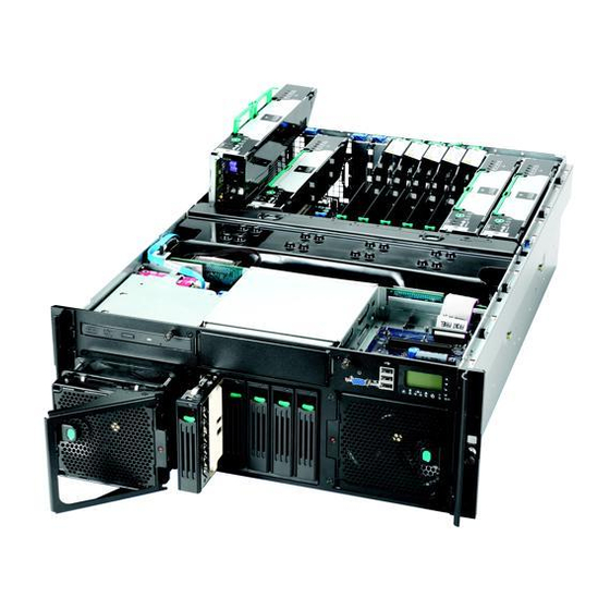
Intel SR4850HW4 - Server Platform - 0 MB RAM Product Manual (267 pages)
Product Guide
Brand:
Intel
| Category:
Desktop
| Size: 6.33 MB
Table of Contents
About this Manual
3
Manual Organization
3
Additional Information and Software
4
Safety Information
5
Safety Cautions
8
Wichtige Sicherheitshinweise
10
Instrucciones de Seguridad Importantes
15
Contents
19
Table of Contents
19
Part I: User's Guide
28
1 Platform Description
29
Figure 1. Intel ® Server Platform SR4850HW4 and SR4850HW4/M Front View
29
Platform Features
30
Table 1. Chassis Feature Summary
30
Platform Front
31
Figure 2. Front Components
31
Standard Control Panel
32
Figure 3. Front Panel Controls and Indicators
33
Intel ® Local Control Panel
34
Figure 4. Intel ® Local Control Panel
35
Platform Rear
36
Figure 5. Rear Platform Features
36
Processors
37
Plug-In Voltage Regulator Module (VRM) Converters
37
System Memory
37
Available Memory Configurations
38
Power Subsystem
40
Power Supply Modules
40
Figure 6. Power Supply Indicators
41
Cooling Subsystem
42
Hot-Swap PCI Slots
42
Table 2. Power Indicator
42
Table 3. Attention Indicator
42
Peripherals
43
Figure 7. Front View of Intel ® Server Platform SR4850HW4 and SR4850HW4/M
43
Figure 8. Hard Disk Drive Carrier
44
Hot-Swap SCSI Hard Disk Drive Support
44
Removable Media Drive Bay Support
45
¼-Inch Half-Height Drive Bay
45
Platform Board Set
45
Figure 9. DVD/CD-ROM Drive Carrier
45
Figure 10. Intel ® Server Platform Block Diagram
46
Main Board
47
Figure 11. Main Board Component Locations
48
Raid Support
49
Scsi Controller
49
Video Support
50
Memory Board
51
Figure 12. Hot-Plug Memory Board Leds and Buttons
52
Figure 13. Front Panel Board Component Locations
52
Front Panel I/O Board
52
SCSI Backplane Board
52
Figure 14. SCSI Backplane Board Component Locations
53
Power Distribution Board
53
Server Management
54
2 Starting up and Shutting down the Server
56
Plugging the Server into AC Power
56
Powering on the Server
56
Shutting down the Server
57
3 Intel® Server Deployment Toolkit
58
Running Software Utilities from the CD
58
4 Server Platform Utilities
59
BIOS Setup Utility
59
Table 4. BIOS Setup Utility
59
Keyboard Commands
60
Table 5. BIOS Setup: Keyboard Commands
60
Configuring Memory Options
61
Memory Mirroring
62
Memory Raid
62
System Configuration Reset
63
Figure 15. Jumper Locations
64
BIOS Upgrades and Recovery
65
BIOS Upgrades with Iflash32
65
Table 6. Iflash32 Utility Command-Line Options and Parameters
66
BIOS Recovery
67
Rolling BIOS
68
Console Redirection
68
Serial Configuration Settings
68
Keystroke Mappings
69
Limitations
69
Table 7. Console Redirection Escape Sequences
69
Interface to Server Management
70
LSI Logic* MPT SCSI Utility
71
Figure 16. LSI SCSI Utility Main Menu
71
Figure 17. Boot Adapter List
72
Figure 18. Global Properties List
73
Figure 19. Adapter Properties
74
Figure 20. Device Properties
75
Figure 21. Adapter And/Or Device Properties Exit Menu
76
Installing the Platform Confidence Test
77
Platform Confidence Test
77
Platform Confidence Test Options
78
System Configuration Wizard (SCW)
78
Starting the System Configuration Wizard
79
Figure 22. System Configuration Wizard Start Screen
79
Using the Server Configuration Wizard Option
80
Figure 23. Configuration Options
81
Configuring Sdrs and Frus
82
Configuring Channels
83
Figure 24. Channels Configuration Screen
83
Figure 25. LAN Channel Setup Screen 1
84
Figure 26. Gateway MAC Address Resolution
85
Figure 27. LAN Channel Setup Screen 2
86
Figure 28. LAN Channel Setup Screen 3
88
Configuring the Serial/Modem Channel
90
Figure 29. Configuring LAN Alert Filters
90
Figure 30. Modem Configuration
91
Figure 31. Remaining Serial/Modem Configuration Parameters
92
Figure 32. Configuring Serial Alerts
93
Figure 33. Configuring Serial Alert Filters
94
Select Users to Configure Screen
95
Figure 34. User Configuration Selection Screen
95
Configure Users Screen
96
Figure 35. User Configuration Screen
96
Setting a System Asset Tag
98
Figure 36. Setting the System Asset Tag
98
Configuring the Advanced Features
99
Figure 37. Advanced Features Configuration Screen 1
99
Figure 38. Advanced Features Configuration Screen 2
101
Figure 39. Advanced Features Configuration Screen 3
102
Saving the Configuration to a Disk
103
Figure 40. Save Server Configuration Screen
103
Saving the Configuration to the Server
104
Running Utilities from the SCW
104
Figure 41. System Configuration Wizard Start Screen
104
Figure 42. Selection Screen for Server Configuration Utilities
105
Creating Diskettes
106
Figure 43. System Configuration Wizard Start Screen
106
Creating Disk Sets by Operating System
107
Figure 44. Choosing Diskette Type
107
Device Driver Diskettes
108
FRUSDR Load Utility
108
Running the FRUSDR Load Utility
109
Checking the Fru Data Integrity
114
SEL Viewer Utility
115
Using the Selviewer Utility
115
Graphical User Interface
116
Figure 45. SEL Viewer Utility Main Window
117
Figure 46. SEL Records in HEX Format
118
Figure 47. File Open Window
119
Figure 48. SEL Properties
120
Figure 49. Confirmation for Clearing SEL
120
Figure 50. General Help Window
121
FRU Viewer Utility
122
Figure 51. about Window
122
Graphical User Interface (GUI)
123
Using the FRU Viewer Utility
123
Figure 52. FRU Viewer Utility Main Window
124
Figure 53. File Open Dialog Box
125
Figure 54. FRU Menu
126
Figure 55. FRU Properties
127
Figure 56. High Resolution Mode
127
Figure 57. Help Window
128
Figure 58. about Window
128
Save and Restore System Configuration (SYSCFG)
129
Upgrading the Firmware
129
Running the Firmware Update Utility
129
Firmware Update Utility Command-Line Options
131
Table 8. FWPIAUPD Command-Line Arguments for Sahalee BMC System
131
Table 9. FWPIAUPD Command-Line Arguments for Direct HSC Update
132
Extensible Firmware Interface (EFI) Shell
133
Table 10. EFI Shell Commands
133
Part II: Service Guide
135
5 User Serviceable Platform Components
135
Tools and Supplies Needed
135
Equipment Log
135
Removing and Installing the Top Cover
135
Removing the Top Cover
136
Figure 59. Removing the Top Cover
136
Installing the Top Cover
137
Figure 60. Installing the Top Cover
137
Hot-Swapping a System Fan Assembly
138
Figure 61. System Fan Location and Removal
138
Hot-Swapping Hard Disk Drives
139
Figure 62. System Fan Module Installation
139
Determining Drive Status
140
Figure 63. Hard Disk Drive Carrier
140
Figure 64. Removing a Hard Disk Drive Carrier
141
Figure 65. Removing the Air Baffle from the Hard Disk Drive Carrier
141
Mounting a Hard Disk Drive in a Carrier
141
Removing a Hard Disk Drive
141
Figure 66. Attaching the Hard Disk Drive to the Carrier
142
Figure 67. Installing Hard Disk Drive into Server
142
Installing a Hard Disk Drive Assembly
142
Hot-Swapping Power Supplies
143
Removing a Power Supply
143
Figure 68. Removing a Power Supply
143
Installing a Power Supply
144
Figure 69. Installing a Power Supply
144
Installing and Removing PCI Cards
145
Removing Hot-Plug PCI Card with Operating System Hot-Plug Interface
145
Figure 70. Removing a PCI Card
146
Removing Hot-Plug PCI Card with Hardware Hot-Plug Interface
147
Figure 71. PCI Slot Attention Button
147
Installing a Hot-Plug PCI Add-In Card
148
Figure 72. Installing a Hot-Plug PCI Add-In Card
148
Removing a Non-Hot-Plug PCI Card
149
Installing a Non-Hot-Plug PCI Card
150
Installing and Removing the Fibre Channel Module
151
Removing the Fibre Channel Module
151
Installing the Fibre Channel Module
152
Figure 73. Installing a Fibre Channel Module
152
Installing and Removing Memory Boards
153
Removing Memory Board Air Baffle
154
Figure 74. Removing Memory Board Air Baffle
154
Installing Memory Board Air Baffle
155
Hot-Removal of a Memory Board
155
Figure 75. Installing Memory Board Air Baffle
155
Figure 76. Memory Module Buttons and Leds
156
Figure 77. Memory Board Removal
157
Hot-Insertion of a Memory Board
158
Figure 78. Installing Memory Board
158
Cold Removal of Memory Board
159
Cold Insertion of a Memory Board
159
Installing and Removing Dimms
160
Rules for Adding Memory
160
Figure 79. Use Only DDR2 Dimms
160
Installing Dimms
161
Figure 80. Remove Memory Board DIMM Cover
161
Figure 81. Install Dimms
162
Figure 82. Install Memory Board DIMM Cover
163
Removing Dimms
164
6 Technician's Serviceable Platform Components
165
Tools and Supplies Needed
165
Safety: before Top Cover Removal
166
Torque Settings
166
Component Locations
166
Table 11. Torque Settings
166
Figure 83. Main Board Component Locations
167
Figure 84. SCSI Backplane Board Component Locations
168
Figure 85. Front Panel Board Component Locations
168
Removing and Installing the Top Cover
169
Removing the Top Cover
169
Figure 86. Removing the Top Cover
169
Installing the Top Cover
170
Figure 87. Installing the Top Cover
170
Removing and Installing the Processor Air Baffle
171
Removing the Processor Air Baffle
171
Figure 88. Removing the Processor Air Baffle
172
Installing the Processor Air Baffle
173
Figure 89. Installing the Processor Air Baffle
173
Figure 90. Engaging the Processor Air Baffle Guides
174
Removing and Installing the Center Brace
175
Removing the Center Brace
175
Figure 91. Removing the Center Brace
176
Installing the Center Brace
177
Figure 92. Installing the Center Brace
177
7 Servicing the Processors
178
Handling the Intel® Xeon® Processors
178
Processor VRM Requirements
179
Installing and Removing a Processor Thermal Blank
179
Removing a Processor Thermal Blank
179
Figure 93. Removing Thermal Blank
180
Installing a Processor Thermal Blank
181
Figure 94. Installing Thermal Blank
181
Installing and Removing a Processor
182
Removing a Processor
182
Installing a Processor
183
Figure 95. Open Processor Socket Lever
183
Figure 96. Set Processor into Socket
184
Figure 97. Close Processor Socket Lever
184
Installing or Removing Processor VRM Converters
185
Removing the Processor Cache VRM Converter
185
Figure 98. Removing a Processor Cache VRM Converter
186
Installing the Processor Cache VRM Converter
187
Figure 99. Installing a Processor Cache VRM Converter
187
Removing the Processor Core VRM Converters
188
Figure 100. Removing Processor 4 Core VRM Baffle
188
Figure 101. Removing Processor 3 Core VRM
189
Figure 102. Removing Processor 4 Core VRM Converter
189
Installing a Processor Core VRM Converter
190
Figure 103. Installing Processor 3 VRM
191
Figure 104. Installing Processor 4 VRM
191
8 Servicing the RAID on Motherboard (ROMB) Components
192
Installing and Removing the Intel® RAID Activation Key
192
Installing the Intel® RAID Activation Key
192
Removing the Intel® RAID Activation Key
194
Installing and Removing the Intel® RAID Smart Battery
195
Installing the Intel® RAID Smart Battery
195
Figure 107. Route and Connect RAID Battery Cable
196
Removing the Intel® RAID Smart Battery
197
Installing and Removing the RAID DDR2-400 DIMM
198
Installing the RAID DDR2-400 DIMM
198
Figure 110. Installing the RAID DDR2-400 DIMM
198
Removing the RAID DDR2 DIMM
199
9 Servicing the Peripheral Area Components
200
Installing the External SCSI Cable Assembly
200
Figure 111. Removing External SCSI Filler Panel
200
Replacing Removable Media Devices
201
Removing the CD-ROM/DVD-ROM Drive
201
Figure 112. Removing the CD-ROM/DVD-ROM Drive Carrier from the Server
201
Figure 113. Removing the CD-ROM/DVD-ROM Drive from the Carrier
202
Installing the CD-ROM/DVD-ROM Drive
203
Figure 114. Assembling the CD-ROM/DVD-ROM Drive and Carrier
203
Figure 115. Inserting the CD-ROM/DVD-ROM Drive Carrier into the Platform
204
10 Servicing the Intel® Management Module
207
Removing the Intel® Management Module
209
11 Servicing the Server Boards
210
Replacing the Main Board
210
Removing the Main Board
210
Figure 120. Removing the Lower Center Air Baffle
210
Figure 121. Removing the PCI Dividers
211
Figure 122. Removing the Main Board
212
Installing the Main Board
213
Figure 123. Installing the Main Board
213
Figure 124. Installing the PCI Card Guide
214
Figure 125. Installing the Lower Center Air Baffle
215
Replacing the SCSI Backplane Board
216
Removing the SCSI Backplane Board
216
Figure 126. Removing the SCSI Backplane Board
217
Installing the SCSI Backplane Board
218
Figure 127. Installing the SCSI Backplane Board
218
Replacing the Power Distribution Board
219
Removing the Power Distribution Board
219
Figure 128. Removing the Power Distribution Board
220
Installing the Power Distribution Board
221
Figure 129. Installing the Power Distribution Board
221
Replacing the Front Panel I/O Board
222
Removing the Front Panel I/O Board
222
Figure 130. Removing the Front Panel I/O Board
222
Installing the Front Panel I/O Board
223
Figure 131. Installing the Front Panel I/O Board
223
12 Replacing the CMOS Battery
224
Figure 132. Removing the Battery
225
Technical Reference
226
Creating DOS-Bootable USB Flash Memory Device
226
Before Beginning
226
Create the DOS-Bootable USB Flash Memory Device
227
Troubleshooting a USB Flash Memory Device
230
System Interconnection
231
Figure 133. Interconnect Block Diagram
231
Table 12. Cable and Connector Descriptions
232
Table 13. Connector Descriptions
232
User Accessible Interconnects
235
Serial Port
235
Table 14. COM1/EMP Serial Connector Pin-Out
235
Video Port
236
Table 15. Video Connector Pin-Out
236
Universal Serial Bus (USB) Interface
237
Table 16. Dual USB Connector Pinout
237
Ethernet Connector
238
Table 17. Dual Ethernet Stacked Connector
238
Server Management LAN Connector (GCM)
240
Table 18. Server Management Ethernet Connector
240
External Ultra 320 SCSI VHDCI Connector
241
Table 19. Ultra 320 SCSI VHDCI Connector Pinout
241
AC Power Input
242
External Ultra320* SCSI Connector (Optional)
242
Figure 134. AC Power Input Connector
242
Figure 135. External SCSI Connector
242
Table 20. External SCSI Connector Pinout
242
Jumper Information
243
Changing Jumper Settings
243
Figure 136. Main Board Jumper Locations
245
I 2 C POST Code Headers
245
Table 21. J3A1 and J6C1 I
245
POST Codes
246
Error Messages and Error Codes
246
POST Leds
246
Table 22. Port 80 POST Code LED Definition
246
POST Progress Codes and Messages
247
Table 23. POST Progress Codes and Messages
247
POST Error Messages and Handling
249
Table 24. BIOS Error Codes
250
POST Error Beep Codes
255
Table 25. Beep Codes
255
Table 26. BIOS Recovery Beep Codes
255
POST Error Pause Option
256
Equipment Log
257
Table 27. Equipment Log
257
Regulatory Specifications and Disclaimers
259
Declaration of the Manufacturer or Importer
259
Fcc Declaration of Conformity
260
Troubleshooting
262
Getting Help
263
Warranty
265
Warranty Limitations and Exclusions
266
Limitations of Liability
266
How to Obtain Warranty Service
266
Telephone Support
267
Returning a Defective Product
267
Advertisement
Advertisement
Related Products
Intel SR1530AHLX - Server System - 0 MB RAM
Intel SR1530AH - Server System - 0 MB RAM
Intel SR1530HAHLX - Server System - 0 MB RAM
Intel SR2600UR - Server System - 0 MB RAM
Intel SR2520SAXSR - Server System - 0 MB RAM
Intel SR6850HW4 - Server Platform - 0 MB RAM
Intel SRSH4 - Server Platform - 0 MB RAM
Intel SR1530 - AHJPCIERISER PCI-E x8 Riser Card
Intel Compute Stick STCK1A8LFC
Intel Compute Stick STK1A32SC
Intel Categories
Motherboard
Computer Hardware
Server
Server Board
Desktop
More Intel Manuals
Login
Sign In
OR
Sign in with Facebook
Sign in with Google
Upload manual
Upload from disk
Upload from URL