Konica Minolta Bizhub C350 Service Manual
Includes: standard controller df-601 pc-101/pc-201 pc-401 ad-501 fs-501
Hide thumbs
Also See for Bizhub C350:
- User manual (502 pages) ,
- Installation manual (12 pages) ,
- Service manual (59 pages)

Related Manuals for Konica Minolta Bizhub C350


Summary of Contents for Konica Minolta Bizhub C350
- Page 1 SERVICE MANUAL FIELD SERVICE Includes: Standard Controller DF-601 PC-101/PC-201 PC-401 AD-501 FS-501 FS-601 2004.03 Ver. 1.0...
-
Page 3: Important Notice
Because of possible hazards to an inexperienced person servicing this product as well as the risk of damage to the product, Konica Minolta Business Technologies, INC. (hereafter called the KMBT) strongly recommends that all servicing be performed only by KMBT- trained service technicians. -
Page 4: Safety Warnings
[1] MODIFICATIONS NOT AUTHORIZED BY KONICA MINOLTA BUSINESS TECHNOLOGIES, INC. Konica Minolta brand products are renowned for their high reliability. This reliability is achieved through high-quality design and a solid service network. Product design is a highly complicated and delicate process where numerous mechanical, physical, and electrical aspects have to be taken into consideration, with the aim of arriving at proper tolerances and safety factors. - Page 5 SAFETY AND IMPORTANT WARNING ITEMS [2] CHECKPOINTS WHEN PERFORMING ON-SITE SERVICE Konica Minolta brand products are extensively tested before shipping, to ensure that all applicable safety standards are met, in order to protect the customer and customer engi- neer (hereafter called the CE) from the risk of injury. However, in daily use, any electrical equipment may be subject to parts wear and eventual failure.
- Page 6 SAFETY AND IMPORTANT WARNING ITEMS WARNING: Power Plug and Cord • When using the power cord (inlet type) that came with this product, be sure to observe the following precautions: a. Make sure the connector is securely inserted in the inlet on the rear panel of the product.
- Page 7 SAFETY AND IMPORTANT WARNING ITEMS WARNING: Wiring • When an extension cord is required, use a specified one. Current that can flow in the extension cord is limited, so using a too long extension cord may result in fire. Do not use an extension cable reel with the cable taken up.
- Page 8 SAFETY AND IMPORTANT WARNING ITEMS CAUTION: Ventilation • The product generates ozone gas during operation, but it will not be harmful to the human body. If a bad smell of ozone is present in the following cases, ventilate the room. a.
- Page 9 SAFETY AND IMPORTANT WARNING ITEMS WARNING: Work Performed with the product Powered • Take every care when making adjustments or performing an operation check with the product powered. If you make adjustments or perform an operation check with the external cover detached, you may touch live or high-voltage parts or you may be caught in moving gears or the timing belt, leading to a risk of injury.
- Page 10 SAFETY AND IMPORTANT WARNING ITEMS WARNING: Safety Checkpoints • Before disassembling or adjusting the write unit (P/H unit) incorporating a laser, make sure that the power cord has been disconnected. The laser light can enter your eye, leading to a risk of loss of eyesight.
- Page 11 SAFETY AND IMPORTANT WARNING ITEMS WARNING: HANDLING OF CONSUMABLE • Toner and developer are not harmful substances, but care must be taken not to breathe excessive amounts or let the substances come into contact with eyes, etc. It may be stimulative.
- Page 12 SAFETY AND IMPORTANT WARNING ITEMS [3] MEASURES TO TAKE IN CASE OF AN ACCIDENT If an accident has occurred, the distributor who has been notified first must immedi- ately take emergency measures to provide relief to affected persons and to prevent further damage.
- Page 13 SAFETY AND IMPORTANT WARNING ITEMS INDICATION OF WARNING ON THE MACHINE Caution labels shown are attached in some areas on/in the machine. When accessing these areas for maintenance, repair, or adjustment, special care should be taken to avoid burns and electric shock. High voltage High temperature High voltage...
- Page 14 SAFETY AND IMPORTA Standard ControllerNT WARNING ITEMS Do not throw into a fire 4036fsS002c0 High voltage High voltage 4036fsS003c0 S-12...
-
Page 15: Main Unit
SERVICE MANUAL FIELD SERVICE Main Unit 2004.03 Ver. 1.0... -
Page 17: Table Of Contents
C350 Field Service Ver. 2.0 April 2004 CONTENTS General System configuration.................... 1-1 Product specifications ..................1-3 Type ........................1-3 Functions ......................1-3 Types of Paper ....................1-4 Maintenance ...................... 1-4 Machine Specifications ..................1-4 Operating Environment..................1-4 Built-in Controllers ..................... 1-5 Maintenance Periodical check .................... - Page 18 C350 Field Service Ver. 2.0 April 2004 1.5.14 Cleaning of the Original Glass ..............2-19 1.5.15 Cleaning of the CCD Sensor ..............2-19 1.5.16 Replacing the Waste Toner Bottle .............. 2-20 1.5.17 Cleaning of the Area around the Waste Toner Collecting Port ....2-21 1.5.18 Replacing Ozone Filter................
- Page 19 C350 Field Service Ver. 2.0 April 2004 4.3.6 Original Glass/IR Front Cover..............2-44 4.3.7 Control Panel ....................2-44 4.3.8 Tray 1 ......................2-45 4.3.9 Tray 2 ......................2-46 4.3.10 Scanner Motor Drive Board ................ 2-46 4.3.11 CCD Unit ....................2-47 4.3.12 Image Processing Board ................
- Page 20 C350 Field Service Ver. 2.0 April 2004 4.3.43 2nd Image Transfer Pressure/Retraction Motor.......... 2-82 4.3.44 Intermediate Transport Motor ..............2-83 4.3.45 Fusing Pressure Roller Pressure/Retraction Motor........2-85 4.3.46 Cleaning Brush Motor ................2-88 4.3.47 AIDC/Registration Sensor/1,2 ..............2-88 4.3.48 LPH ......................2-90 4.3.49 ATDC Sensor Y/M/C...................
- Page 21 C350 Field Service Ver. 2.0 April 2004 3.10 Unit Life Indication ................... 3-15 3.11 Settings in the Admin. Mode................3-16 3.11.1 Admin. Set....................3-16 3.12 Settings in Volume Track (E. K. C.) ..............3-20 3.12.1 Volume Track Mode (E. K. C.)..............3-20 3.12.2 Volume Track Setting (E.
- Page 22 C350 Field Service Ver. 2.0 April 2004 Tech. Rep. Mode function setting procedure ........... 3-39 Touch Panel Adj....................3-40 Tech. Rep. Mode function tree................. 3-41 Machine Adjust....................3-43 4.4.1 Fuser Nip....................3-43 4.4.2 Fuser Temp....................3-43 4.4.3 Fuser Speed....................3-44 4.4.4...
- Page 23 C350 Field Service Ver. 2.0 April 2004 4.8.6 Book Erase (Center) ................... 3-69 4.8.7 Peripheral Setting ..................3-69 4.8.8 Server set (KRDS) / Server set (RD)............3-70 4.8.9 Unit Change....................3-72 4.8.10 Reprint ......................3-72 4.8.11 Hard Disk....................3-73 4.8.12 Display PM parts lifetime ................
- Page 24 C350 Field Service Ver. 2.0 April 2004 4.13.5 Solid pattern ....................3-92 4.13.6 Color sample ....................3-92 4.13.7 8 Color Solid Pattern .................. 3-93 4.13.8 LPH Pattern....................3-93 4.14 ADF Check ...................... 3-94 4.14.1 Original Stop Position ................. 3-94 4.14.2 Registration Loop ..................
- Page 25 C350 Field Service Ver. 2.0 April 2004 Date/Time input mode ..................3-106 Date/Time input mode screen................ 3-106 Date/Time input mode setting procedure............3-106 IV Troubleshooting Jam Display ......................4-1 Misfeed Display....................4-1 1.1.1 Misfeed Display Resetting Procedure............4-1 Sensor layout ..................... 4-2 1.2.1...
- Page 26 C350 Field Service Ver. 2.0 April 2004 2.3.14 P-31: Black PC Drum Sensor malfunction ..........4-17 Trouble code ....................4-18 2.4.1 Trouble code list ..................4-18 How to reset ....................4-26 Solution ......................4-27 2.6.1 C0000: Main Motor's failure to turn ............4-27 2.6.2...
- Page 27 C350 Field Service Ver. 2.0 April 2004 2.6.34 C0650: Scanner Home Sensor malfunction ..........4-36 2.6.35 C0660: Scanner overrun failure..............4-36 2.6.36 C0900: 2nd Drawer Lift-Up Motor Failure ........... 4-37 2.6.37 C0960: Manual Bypass Paper Lifting Failure..........4-37 2.6.38 C0F30: Abnormally low toner density detected Cyan ATDC Sensor ..4-38 2.6.39 C0F32: Abnormally low toner density detected Magenta ATDC Sensor ..
- Page 28 C350 Field Service Ver. 2.0 April 2004 2.6.71 C12C0: Hard disk recognition error............4-44 2.6.72 C12C1: Hard Disk Error 1 ................4-44 2.6.73 C12C2: Hard Disk Error 2 ................4-44 2.6.74 C12C3: Hard Disk Error 3 ................4-44 2.6.75 C12C4: Hard Disk Error 4 ................4-44 2.6.76 C12C5: Hard Disk Error 5 ................
- Page 29 C350 Field Service Ver. 2.0 April 2004 Machine is not Energized at All (PU1 Operation Check) ......... 4-49 Control panel indicators do not light..............4-49 Fusing Heaters do not Operate ............... 4-50 Power is not Supplied to Options..............4-50 3.4.1...
- Page 30 C350 Field Service Ver. 2.0 April 2004 4.3.20 Printer Monocolor: void areas, white spots ..........4-78 4.3.21 Printer Monocolor: colored spots ............... 4-79 4.3.22 Printer Monocolor: blurred image............... 4-80 4.3.23 Printer Monocolor: blank copy, black copy ..........4-81 4.3.24 Printer Monocolor: 0.5-mm-pitch uneven image ........4-82 4.3.25 Printer Monocolor: 2-mm-pitch uneven image ...........
- Page 31 C350 Field Service Ver. 2.0 April 2004 PK-501 (Option)....................5-17 AD-501 (Option)....................5-18 Connector layout drawing................... 5-19 Timing chart ....................... 5-23 Main unit ......................5-23 DF-501......................5-24 3.2.1 1-sided mode....................5-24 3.2.2 Mixed original detection mode..............5-28...
- Page 32 C350 Field Service Ver. 2.0 April 2004...
-
Page 33: System Configuration
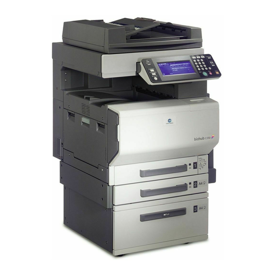
C350 Field Service Ver.2.0 Apri. 2004 System configuration I General System configuration 1/2 System Front View [11] [12] [13] [10] Machine Job Separator JS-601 Automatic Duplex Unit AD-501 Finisher FS-601 Paper Feed Cabinet PC-201 [10] Punch Kit PK-501 for FS-601... - Page 34 System configuration bizhub C350 Field Service Ver.2.0 April 2004 2/2 System Rear View [10] [11] Machine Local Interface Kit EK-501 Vender Kit VK-501 Mechanical Counter (South Central America, North America, Europe Only) Data Terminal DT-105 Key Counter Kit KIT-1 (South Central America, North America...
-
Page 35: Product Specifications
C350 Field Service Ver.2.0 Apri. 2004 Product specifications Product specifications Type Type Desktop-type printer integrated with scanner Copying System Electrostatic dry-powdered image transfer to plain paper Printing Process Tandem-type indirect electrostatic recording system PC Drum Type OPC (organic photo conductor) -
Page 36: Types Of Paper
Product specifications bizhub C350 Field Service Ver.2.0 April 2004 Types of Paper Paper Source Tray1 Tray2 Multiple Bypass ❍ ❍ ❍ Plain paper (60 to 90 g/m Translucent paper – – – OHP transparencies – (crosswise feeding only) Thick paper 1 –... -
Page 37: Built-In Controllers
C350 Field Service Ver.2.0 Apri. 2004 Product specifications Built-in Controllers Printer Driver PCL5c printer driver Scan Driver TWAIN driver OS Compatibility Windows 98/Me, Windows NT/2000/XP, Windows Server 2003 Interface Ethernet 10/100BaseTX NOTE • These specifications are subject to change without notice. - Page 38 Product specifications bizhub C350 Field Service Ver.2.0 April 2004 Blank page...
-
Page 39: Ii Maintenance
C350 Field Service Ver.2.0 April 2004 Periodical check II Maintenance Periodical check Service schedule Guarantee period (5-year or 800,000 prints) × 10,000-print Per cycle × print Number number of times 6 12 15 18 20 24 30 36 40 42 45 48 54 60 66 72 75 Upon each call ●... -
Page 40: Maintenance Call (Per 60,000-Print)
Periodical check bizhub C350 Field Service Ver. 2.0 April 2004 1.2.2 Maintenance call (per 60,000-print) Number of Lubrica- Descrip- Class Parts to be replaced Check Clean Replace personnel tion tions Paper take-up and ● image conditions Overall ● ● Appearance ●... -
Page 41: Periodical Parts Replacement 3 (Per 300,000-Print)
C350 Field Service Ver.2.0 April 2004 Periodical check 1.2.5 Periodical parts replacement 3 (per 300,000-print) Number of Lubri- Class Parts to be replaced Check Clean Replace Descriptions personnel cation Paper take-up and ● image conditions Overall ● ● Appearance ●... -
Page 42: Maintenance Parts
Periodical check bizhub C350 Field Service Ver. 2.0 April 2004 Maintenance parts • To ensure that the machine produces good copies and to extend its service life, it is rec- ommended that the maintenance jobs described in this schedule be carried out as instructed. - Page 43 C350 Field Service Ver.2.0 April 2004 Periodical check B. Option Ref.Page Class Maintenance parts Clean Replace Descriptions in this manual Pick-up Roller 50 k 200 K Replace those Paper Take-up Roller 50 k 200 K three parts at the same time.
-
Page 44: Concept Of Parts Life
Periodical check bizhub C350 Field Service Ver. 2.0 April 2004 Concept of parts life Life value Max. number of Description (Specification printed pages value) A waste toner full condition is detected when about Waste Toner 8,000 printed pages have been produced after a –... - Page 45 C350 Field Service Ver.2.0 April 2004 Periodical check A. Conditions for Life Specifications Values • The life specification values represent the number of copies made or figures equivalent to it when given conditions (see the Table given below) are met. They can be more or less depending on the machine operating conditions of each individual user.
-
Page 46: Maintenance Procedure (Periodical Check Parts)
Periodical check bizhub C350 Field Service Ver. 2.0 April 2004 Maintenance procedure (Periodical check parts) NOTE • The alcohol described in the cleaning procedure of Maintenance represents the isopropyl alcohol. 1.5.1 Paper Take-up Roller A. Cleaning Procedure 1. Slide out the Tray 1. -
Page 47: Separation Roller 2
C350 Field Service Ver.2.0 April 2004 Periodical check 3. Using a soft cloth dampened with alcohol, wipe the Separation Roller [3] clean of dirt. 4036fs2014c1 B. Replacing Procedure 1. Slide out the Tray 1. 2. Remove two screws [1] and the Sep- aration Roller mounting bracket Assy [2] and two reinforcement plates [3]. - Page 48 Periodical check bizhub C350 Field Service Ver. 2.0 April 2004 4. Open the Vertical transport door. 5. Remove two Claws [3] and the Verti- cal transport door [4]. 4036fs2019c0 6. Remove two Screws [5], and remove the Jam processing cover [6].
-
Page 49: Paper Take-Up Roller
C350 Field Service Ver.2.0 April 2004 Periodical check B. Replacing Procedure 1. Remove the Separation Roller 2 installation plate Assy. ☞ See the procedures 1 to 7 in 2-9 “Cleaning of Separation Roller”. 2. Remove two C-rings [1] and the Shaft [2], and remove the Separation Roller fixing plate Assy [3]. - Page 50 Periodical check bizhub C350 Field Service Ver. 2.0 April 2004 3. Remove two Screws [3] and Connec- tor [4], and remove the Paper Take- up Roller Assy [5]. 4036fs2024c1 4. Remove two Screws [6] and the Installation flame [7] of the Separa- tion Roller 2 installation plate Assy.
- Page 51 C350 Field Service Ver.2.0 April 2004 Periodical check 7. Remove the C-ring [13] and Gear [14] while sliding out the Shaft Assy [12] in the direction indicated in left figure. [12] [14] [13] 4036fs2028c2 8. Remove the C-ring [15] and Bushing [16], and remove the Shaft Assy [17].
-
Page 52: Pick-Up Roller
Periodical check bizhub C350 Field Service Ver. 2.0 April 2004 1.5.5 Pick-up Roller A. Cleaning Procedure 1. Remove the Separation Roller 2 installation plate Assy. ☞ See the procedures 1 to 7 in 2-9 “Cleaning of Separation Roller 2”. 2. Using a soft cloth dampened with alcohol, wipe the Pick-up Roller [1]. -
Page 53: Transport Roller
C350 Field Service Ver.2.0 April 2004 Periodical check 5. Remove two Screws [8] and Paper Take-up Roller cover [9]. 4036fs2026c1 6. Remove two C-rings [10] and two [10] Bushings [11], and remove the Pick- [12] up Roller Assy [12]. -
Page 54: Cleaning Of Synchronizing Roller
Periodical check bizhub C350 Field Service Ver. 2.0 April 2004 1.5.7 Cleaning of Synchronizing Roller 1. Open the Right Door. 2. Remove the Paper Dust Remover. ☞ See 2-16 for Replacing the Paper Dust Remover. 3. Using a soft cloth dampened with alcohol, wipe the Synchronizing Roll- ers [1] clean of dirt. -
Page 55: Cleaning Of Transport Roller
C350 Field Service Ver.2.0 April 2004 Periodical check 1.5.9 Cleaning of Transport Roller 1. Open the Right Door. 2. Using a soft cloth dampened with alcohol, wipe the Transport Roller [1] clean of dirt. 4036fs2519c0 1.5.10 Cleaning of 2nd Image Transfer Entrance Upper Guide 1. -
Page 56: Cleaning Of The Mirrors (1St/2Nd/3Rd)
Periodical check bizhub C350 Field Service Ver. 2.0 April 2004 4. Using a soft cloth dampened with alcohol, wipe the Scanner Rails [4] clean of dirt. NOTE • Apply lubricant after cleaning. 4036fs2506c0 1.5.12 Cleaning of the Mirrors (1st/2nd/3rd) 1. Remove the Original Glass. -
Page 57: Cleaning Of The Original Glass
C350 Field Service Ver.2.0 April 2004 Periodical check 1.5.14 Cleaning of the Original Glass 1. Using a soft cloth dampened with alcohol, wipe the Original Glass [1] clean of dirt. 4036fs2508c0 1.5.15 Cleaning of the CCD Sensor 1. Remove the Original Glass. -
Page 58: Replacing The Waste Toner Bottle
Periodical check bizhub C350 Field Service Ver. 2.0 April 2004 1.5.16 Replacing the Waste Toner Bottle NOTES • If a Finishing Option is installed, remove if from the Main Unit before trying to replace the Waste Toner Bottle. • When removing the Finishing Option, support the Horizontal Transport Unit with your hand to prevent if from dropping. -
Page 59: Cleaning Of The Area Around The Waste Toner Collecting Port
C350 Field Service Ver.2.0 April 2004 Periodical check 1.5.17 Cleaning of the Area around the Waste Toner Collecting Port 1. Open the Rear Left Cover. 2. Remove the Waste Toner Bottle [1]. 4036fs2045c1 3. Wipe the areas around the Waste... -
Page 60: Cleaning Lph Assy
Periodical check bizhub C350 Field Service Ver. 2.0 April 2004 1.5.20 Cleaning LPH Assy NOTE • After the Imaging Unit has been removed from the main unit, be sure to place it in the plastic bag (black) or wrap it in a light shielding cloth, and store it in a dark place. -
Page 61: Replacing The 2Nd Image Transfer Roller Unit
C350 Field Service Ver.2.0 April 2004 Periodical check 1.5.22 Replacing the 2nd Image Transfer Roller Unit NOTES • If a Finishing Option is installed, remove if from the main unit before trying to replace the Waste Toner Bottle. • When removing the Finishing Option, support the horizontal transport unit with your hand to prevent if from dropping. -
Page 62: Image Transfer Belt Unit
Periodical check bizhub C350 Field Service Ver. 2.0 April 2004 1.5.23 Image Transfer Belt Unit A. Cleaning Procedure 1. Remove the Image Transfer Belt Unit. ☞ 2-24 2. Using a dried soft cloth, wipe the Transfer belt. NOTES • If it is difficult to clean with dried... - Page 63 C350 Field Service Ver.2.0 April 2004 Periodical check 5. Open the Left Door. 6. Grasp the handle, and remove the waste toner bottle [3]. NOTES • Raise the waste toner bottle gently before removing it. • If scattered toner has accumulated...
-
Page 64: Replacing The Imaging Unit (C, M, Y, Bk)
Periodical check bizhub C350 Field Service Ver. 2.0 April 2004 3. Hold the handle and install the Waste Toner Bottle [3] in position. 4. Close the Left Door. 5. Close the Right Door. NOTE • Make sure that the door is locked in position both at front and rear. - Page 65 C350 Field Service Ver.2.0 April 2004 Periodical check B. Reinstallation Procedure 1. Remove the Imaging Unit from its plastic bag. 2. Tilt the Imaging Unit [1] to the left and shake it a small stroke in the tilt direction twice. Then, tilt it to the right and shake it a small stroke in the tilt direction twice.
- Page 66 Periodical check bizhub C350 Field Service Ver. 2.0 April 2004 4. Pull out the PC Drum protective sheet [3] while pressing the IU. NOTE • Pull out the PC Drum protective sheet half way, and pull it down slantwise. 4036fs2582c0 5.
-
Page 67: Replacing The Fusing Unit
C350 Field Service Ver.2.0 April 2004 Periodical check 1.5.25 Replacing the Fusing Unit NOTE • Before replacing the Fusing Unit, ensure that it has had time to cool down. 1. Turn OFF the main switch and unplug the power cord from the power outlet, then wait for about 20 minutes. -
Page 68: Service Tool
Service tool bizhub C350 Field Service Ver. 2.0 April 2004 Service tool CE Tool list Tool name Shape Personnel Remarks Scanner Drive Cable Holding Jig 4036fs2001c0 LED Cleaning Jig 4036fs2002c0 LED Cleaning Jig Pad 4036fs2003c0 LPH Assy Mounting Jigs 4036fs2004c0... -
Page 69: Copy Materials
C350 Field Service Ver.2.0 April 2004 Service tool Copy materials 2.2.1 Imaging Unit Single Parts (IU) Parts name Replacing period IU Black 80,000 copies IU Yellow 50,000 copies IU Magenta 50,000 copies IU Cyan 50,000 copies ☞ For the predetermined conditions, see 2-7. -
Page 70: Firmware Upgrade
Firmware upgrade bizhub C350 Field Service Ver. 2.0 April 2004 Firmware upgrade Preparations for Firmware rewriting 3.1.1 Service environment • OS: Windows2000 • Drive which enables writing/reading of Compact flash • Compact flash (with 64MB or more) 3.1.2 Application to be used •... -
Page 71: Writing Into The Compact Flash
C350 Field Service Ver.2.0 April 2004 Firmware upgrade 5. Set the following two values as the Windows Environmental Variable. Variable name Variable value CYGWIN ntsec HOME /home/username 4036fs2621e0 3.1.4 Writing into the Compact flash 1. Put the data of Firmware in the optional directory. (C:\TSS2 in the below figure) - Page 72 Firmware upgrade bizhub C350 Field Service Ver. 2.0 April 2004 3. Mount the Compact flash on the PC, and check the Drive name, which was recognized in the Windows. (F-Drive in the following figure) 4036fs2623e0 → → → 4. Click “Start”...
-
Page 73: Firmware Rewriting
C350 Field Service Ver.2.0 April 2004 Firmware upgrade Firmware rewriting • The F/W is updated using the Compact flash. 3.2.1 Updating method NOTE • NEVER remove or insert the Compact Flash card with the machine power turned 1. With the Power Switch in the OFF position, unplug the power cord from the power outlet. -
Page 74: Action When Data Transfer Fails
Firmware upgrade bizhub C350 Field Service Ver. 2.0 April 2004 3.2.2 Action When Data Transfer Fails • If “NG” appears on the Touch Panel, indicating that rewriting has been unsuccessful (in which case the Start key lights up red), take the following steps. -
Page 75: Other
C350 Field Service Ver.2.0 April 2004 Other Other Disassembly/Adjustment prohibited items A. Paint-locked Screws NOTE • Paint-locked screws show that the assembly or unit secured can only be adjusted or set at the factory and should not be adjusted, set, or removed in the field. -
Page 76: Disassembly/Assembly List (Other Parts)
Other bizhub C350 Field Service Ver. 2.0 April 2004 Disassembly/Assembly list (Other parts) Section Part name Ref.Page ☞ Original Glass 2-44 ☞ IR Upper Right Cover 2-43 ☞ Control Panel 2-44 ☞ IR Front Cover 2-44 ☞ IR Upper Front Cover 2-43 ☞... - Page 77 C350 Field Service Ver.2.0 April 2004 Other Section Part name Ref.Page ☞ Multi Bypass Unit 2-59 ☞ Unit Hopper Unit 2-62 ☞ LPH Unit 2-64 ☞ Scanner Motor 2-66 ☞ Scanner Assy 2-68 ☞ Scanner Wire 2-69 ☞ PWB Box 2-76 ☞...
-
Page 78: Disassembly/Assembly Procedure
Other bizhub C350 Field Service Ver. 2.0 April 2004 Disassembly/Assembly procedure 4.3.1 IR Right Cover/Front Right Cover/Bypass Right & Left Cover 4036fs2050c1 1. Remove four Screws [1], and remove the IR Right Cover [2]. 2. Remove the Panel Cover. ☞ 2-42 3. -
Page 79: Exit Tray/Ir Left Cover/Rear Left Cover/Left Front Cover
C350 Field Service Ver.2.0 April 2004 Other 4.3.2 Exit Tray/IR Left Cover/Rear Left Cover/Left Front Cover [10] 4036fs2167c1 1. Open the Front Door [1]. 2. Remove two Screws [2], and remove the Exit Tray [3]. 3. Remove four Screws [4], and remove the IR Left Cover [5]. -
Page 80: Front Door/Panel Cover/Paper Setting Dial Cover
Other bizhub C350 Field Service Ver. 2.0 April 2004 4.3.3 Front Door/Panel Cover/Paper Setting Dial Cover 4036fs2168c1 1. Open the Front Door [1]. 2. Remove the Screw [2], and remove the Panel Cover [3]. 3. Pick up the Front Door [1] and remove it. -
Page 81: Ir Upper Front Cover/Ir Upper Right Cover/Ir Upper Rear Cover
C350 Field Service Ver.2.0 April 2004 Other [10] [12] [11] [13] [11] 4036fs2157c1 5. Remove five Screws [9], and remove the Rear Cover [10]. 6. Remove four Screws [11]. 7. Open the Right Door [12], and remove the Rear Right Cover [13]. -
Page 82: Original Glass/Ir Front Cover
Other bizhub C350 Field Service Ver. 2.0 April 2004 4.3.6 Original Glass/IR Front Cover 4036fs2159c2 1. Remove the IR Upper Right Cover. ☞ 2-43 2. Remove each Screw [1], and remove the Original Glass fixing bracket (near side/ inmost side) [2]. -
Page 83: Tray 1
C350 Field Service Ver.2.0 April 2004 Other 2. Remove four Screws [2]. 4036fs2161c0 3. Remove the Flat Cable [3]. 4. Remove the Control Panel [4]. 4036fs2162c0 4.3.8 Tray 1 1. Slide out the Tray 1 [1]. 4036fs163c0 2. Slide out the Tray 1 [3] while press- ing the Slide Locks [2] at both ends. -
Page 84: Tray 2
Other bizhub C350 Field Service Ver. 2.0 April 2004 4.3.9 Tray 2 1. Slide out the Tray 2 [1]. 4036fs165c0 2. Remove one Screw [2], and remove the Stopper [3]. 3. Slide out the Tray 2 while pressing the Slide Locks [4]. -
Page 85: Ccd Unit
C350 Field Service Ver.2.0 April 2004 Other 4.3.11 CCD Unit A. Removal Procedure 1. Remove the Original Glass. ☞ 2-44 2. Remove seven Screws [1], and remove the CCD Unit Cover [2]. 4036fs2613c0 3. Remove four Screws [3] and Flat Cable [4], and remove the CCD Unit [5]. -
Page 86: Image Processing Board
Other bizhub C350 Field Service Ver. 2.0 April 2004 4.3.12 Image Processing Board 1. Remove the Rear Cover and IR Right Cover. ☞ 2-42 2. Remove four Screws [1], and remove the IR Frame Protective Cover [2]. 4036fs2178c0 3. Remove seven Screws [3], and remove the Board Cover [4]. -
Page 87: Control Board
C350 Field Service Ver.2.0 April 2004 Other 6. Remove six Screws [6] and two Bolts [7], and remove the Image Process- ing Board [8]. 4036fs2057c1 4.3.13 Control Board 1. Remove the Lower Rear Cover. ☞ 2-42 2. Remove all the Connectors on the Control Board. -
Page 88: Mfp Control Board
Other bizhub C350 Field Service Ver. 2.0 April 2004 Cautions in replacing the Control Board: • When Control Board (PWB-MC) is replaced, relocate the EEPROM (IC45). Mount the EEPROM (IC45) of old Control Board onto the new Control Board. 4036fs2591c0 NOTE •... - Page 89 C350 Field Service Ver.2.0 April 2004 Other 3. Remove two Connectors [3] and 13 Screws [4]. 4036fs2062c1 4. Remove five Screws [5]. 5. Remove two Screws [6] and two Bolts [7], and remove the Interface Cover [8]. 6. Remove the MFP Control Board Assy [9].
-
Page 90: High Voltage Unit/1
Other bizhub C350 Field Service Ver. 2.0 April 2004 NOTE • When RAM IC (IC418) is mounted, precisely fit the directions of each “A”. 4036fs2599c0 4.3.15 High Voltage Unit/1 1. Remove the PWB Box. ☞ 2-76 2. Remove four Screws [1] and eight Connectors [2], and remove two Har- ness Rails [3]. -
Page 91: High Voltage Unit/2
C350 Field Service Ver.2.0 April 2004 Other 4.3.16 High Voltage Unit/2 1. Remove the PWB Box. ☞ 2-76 2. Remove all the Connectors on the High Voltage Unit/2 [1]. 4036fs2068c1 3. Remove two Screws [2], and remove the High Voltage Unit/2 Assy [3]. -
Page 92: Tray 1 Paper Size Board
Other bizhub C350 Field Service Ver. 2.0 April 2004 4.3.17 Tray 1 Paper Size Board 1. Slide out the Tray 1. 2. Remove the PWB Box. ☞ 2-76 3. Remove the Connector [1] on the High Voltage Unit/2. 4. Remove two Screws [2] and Connec- tor [3], and remove the Tray1 Paper Size Board Assy [4]. - Page 93 C350 Field Service Ver.2.0 April 2004 Other 3. Unplug all connectors from the DC Power Supply. 4036fs2074c1 4. Remove seven Screws [3], and remove the DC Power Supply Assy [4]. 4036fs2075c1 5. Remove four Screws [5], and remove the Protective Cover [6].
-
Page 94: Led Drive Board
Other bizhub C350 Field Service Ver. 2.0 April 2004 6. Remove 12 Screws [7], and remove the DC power Supply [8]. 4036fs2077c1 4.3.19 LED Drive Board 1. Remove the LPH Unit. ☞ 2-64 2. Remove two screws [1], unplug the connector [2] each, and remove each guide Assy. -
Page 95: Paper Type Board
C350 Field Service Ver.2.0 April 2004 Other 4.3.20 Paper Type Board 1. Remove the Paper Setting Dial Cover. ☞ 2-42 2. Remove the Dial [1]. 4036fs2144c0 3. Remove the Screw [2], Connector [3], and Holder [4], and remove the Paper Type Board [5]. -
Page 96: Tray 2 Board
Other bizhub C350 Field Service Ver. 2.0 April 2004 4.3.22 Tray 2 Board 1. Remove the Tray 2 Rear Cover. ☞ 2-42 2. Remove all the Connectors on the Tray 2 Board. 4036fs2147c1 3. Remove four Screws [1], and remove the Tray 2 Board [2]. -
Page 97: Inverter Board
C350 Field Service Ver.2.0 April 2004 Other 5. Remove the Lever [6], and remove the Tray 2 Paper Size Board [7]. 4036fs2151c0 4.3.24 Inverter Board 1. Remove the Scanner Assy. ☞ 2-68 2. Remove four Screws [1], Flat Cable [2] and Connector [3], and remove the Inverter Board [4]. -
Page 98: Replacement Of The Manual Bypass Paper Take-Up Roller
Other bizhub C350 Field Service Ver. 2.0 April 2004 3. Remove the Screw [4], and remove the Bypass Left Cover [5]. 4036fs2080c1 4. Remove four Screws [6], and remove the Multi Bypass Unit [7]. 4036fs2081c1 4.3.26 Replacement of the Manual Bypass Paper Take-Up Roller 1. -
Page 99: Replacement Of The Manual Bypass Separator Roll Assy
C350 Field Service Ver.2.0 April 2004 Other 4. Remove five screws and the Manual Bypass Unit Lower Frame. 4030D036AA 5. Remove one C clip and the Manual Bypass Paper Take-Up Clutch. 6. Snap off one C-clip of the Paper Take-Up Roll and one bushing. -
Page 100: Toner Hopper Unit
Other bizhub C350 Field Service Ver. 2.0 April 2004 6. Remove four screws and the Manual Bypass Transport Cover. 7. Remove two screws andthe manual Bypass Separator Fixing Bracket Assembly. CAUTION • Install the Manual Bypass Separa- tor Fixing Bracket while pressing... - Page 101 C350 Field Service Ver.2.0 April 2004 Other 7. Remove two Terminals [5]. NOTE • For installation of Hopper Unit, con- nect the Terminals in the sequence of blue and then white from upper. 4036fs2084c0 8. Disconnect five connectors [6].
-
Page 102: Lph Unit
Other bizhub C350 Field Service Ver. 2.0 April 2004 4.3.29 LPH Unit 1. Open the Front Door. 2. Slide out the IU (C, M, Y, Bk). NOTE • After the IU has been pulled out, place the IU lock lever back into the locked posi- tion. - Page 103 C350 Field Service Ver.2.0 April 2004 Other 8. Remove the Screw [6] and Connec- tor [7]. 4036fs2618c0 9. Remove the Connector [8]. 4036fs2089c2 10. Turning the IU (C, M, Y, Bk) drive hub [9], push it into the locked position (at four places).
-
Page 104: Scanner Motor
Other bizhub C350 Field Service Ver. 2.0 April 2004 NOTES • After replacing the LPH Unit, be [12] sure to turn four Drive Hubs [12] to release locking. Proceeding with job while still being locked may unintentionally release the locking condition, thus damaging the Drive hub. - Page 105 C350 Field Service Ver.2.0 April 2004 Other 4. Remove three screws [4] and the Scanner Motor Assy [5]. 4036fs2523c0 5. Remove two screws [6] and the Scanner Motor [7]. 4036fs2524c0 B. Reinstallation Procedure 1. Temporarily secure the Scanner Motor Assy [2] using three screws [1].
-
Page 106: Scanner Assy
Other bizhub C350 Field Service Ver. 2.0 April 2004 4.3.31 Scanner Assy 1. Remove the Original Glass. ☞ 2-44 2. Move the Scanner Assy [1] to the location shown and remove one mounting screw each at the front and rear end. -
Page 107: Scanner Drive Cables
C350 Field Service Ver.2.0 April 2004 Other 4.3.32 Scanner Drive Cables A. Removal Procedure 1. Remove the Rear Cover. ☞ 2-42 2. Remove the Control Panel. ☞ 2-44 3. Remove four Presser Bars [1] of Flat Cable. 4036fs2094c0 4. Remove the IR Front Cover. - Page 108 Other bizhub C350 Field Service Ver. 2.0 April 2004 12. Remove the screw [8] and the Scan- ner drive gear [9]. 4036fs2550c0 13. Snap off the C-clip [10] and remove the bushing [11] (front). [11] [10] 4036fs2551c0 14. Slide the shaft [12] toward the rear...
-
Page 109: Winding Of The Scanner Drive Cables
C350 Field Service Ver.2.0 April 2004 Other 4.3.33 Winding of the Scanner Drive Cables <Overall figure> 4036fs2553c0 A. Reinstallation Procedure <Front> 1. Position the round bead [1] of the Scanner Drive Cable in the pulley [2] as shown. NOTE •... - Page 110 Other bizhub C350 Field Service Ver. 2.0 April 2004 3. Wind the hook end of the cable around the pulley five turns counter- clockwise, from the front toward the rear side. NOTE • Make sure that no part of the cable rides on the other.
- Page 111 C350 Field Service Ver.2.0 April 2004 Other 8. Slip the Cable Holding Jig [6] onto the pulley to secure the cable in posi- tion. 4036fs2561c0 9. Install the front and rear pulleys [7] and bushings [8] onto the shaft [9] and fit the C-clip [10].
- Page 112 Other bizhub C350 Field Service Ver. 2.0 April 2004 NOTE [17] [18] • Mount the Screw [16] in the direc- tion that is opposite against the direction for which Scanner Drive Gear [17] and Screw [18] are screwed together as shown in the left figure.
- Page 113 C350 Field Service Ver.2.0 April 2004 Other <Rear> [29] 17. Wind the bead end of the cable [29] around pulley F [30] and pulley E [32] [31] [31], then hook the bead [32] onto the Adjustable Anchor [33]. [30]...
-
Page 114: Pwb Box
Other bizhub C350 Field Service Ver. 2.0 April 2004 4.3.34 PWB Box 1. Remove the Rear Right Cover, Rear Left Cover, Rear Cover and Upper Rear Cover. ☞ 2-41 2. Remove 12 Screws [1], and remove the Protective Shield [2]. -
Page 115: Main Motor
C350 Field Service Ver.2.0 April 2004 Other 8. Remove 11 Screws [10] and two Connectors [11], and remove the PWB Box [12]. [10] [10] [10] [11] [12] [10] 4036fs2099c2 4.3.35 Main Motor 1. Remove the PWB Box. ☞ 2-76 2. -
Page 116: Toner Supply Motor C/Bk
Other bizhub C350 Field Service Ver. 2.0 April 2004 3. Remove two Shoulder screws [3] and two Connectors [4], and remove the Fan Assy [5]. 4036fs2102c2 4. Remove four Screws [6] and Con- nector [7], and remove the Fusing Drive Motor [8]. -
Page 117: Color Pc Drum Motor
C350 Field Service Ver.2.0 April 2004 Other 3. Remove the Connector [3]. 4036fs2105c0 4. Remove two screws [4]. Then, turn the Toner Replenishing Motor Y/M [5] counterclockwise and take it off the machine. 4036fs2530c1 4.3.39 Color PC Drum Motor 1. - Page 118 Other bizhub C350 Field Service Ver. 2.0 April 2004 Cautions when mounting the Color PC Drum Motor: • Before mounting the Color PC Drum Motor, be sure to check the assembled posi- tion of PC Gear. If its position is improper, make positioning adjustment.
-
Page 119: Color Developing Motor
C350 Field Service Ver.2.0 April 2004 Other NOTE • When the Upper Frame Assy is removed, adjustment should be performed at hole A [1], hole B [2] and hole C [3] while the Color Developing Motor is being removed. -
Page 120: 1St Image Transfer Pressure/Retraction Motor
Other bizhub C350 Field Service Ver. 2.0 April 2004 4.3.42 1st Image Transfer Pressure/Retraction Motor 1. Remove the PWB Box. ☞ 2-76 2. Remove the High Voltage Unit/1. ☞ 2-52 3. Remove two Screws [1] and Connec- tor [2], and remove the Dust Suction Fan Assy [3]. -
Page 121: Intermediate Transport Motor
C350 Field Service Ver.2.0 April 2004 Other 3. Remove four screws [2], unplug the connector [3], and remove the gear Assy [4] and motor Assy [5]. 4036fs2531c0 4. Remove two screws [6] and the 2nd Image Transfer Pressure/Retraction Motor [7]. - Page 122 Other bizhub C350 Field Service Ver. 2.0 April 2004 4. Remove three Screws [6], and remove the Holder [7]. 4036fs2114c0 5. Remove the C-ring [8], and remove the Gear 1 [9]. 4036fs2115c0 6. Remove the C-ring [10], and remove the Gear 2 [11].
-
Page 123: Fusing Pressure Roller Pressure/Retraction Motor
C350 Field Service Ver.2.0 April 2004 Other 9. Remove the Screw [16], and remove [17] [16] the Sensor Assy [17]. 4036fs2119c1 10. Remove two Screws [18], and remove the Intermediate Transport [19] Motor [19]. NOTES • Remove the Intermediate Transport... - Page 124 Other bizhub C350 Field Service Ver. 2.0 April 2004 8. Remove two Screws [8], and remove the Harness Guide [9]. 4036fs2122c1 9. Remove four Screws [10]. [10] [10] 4036fs2124c1 10. Remove six Connectors [11]. [11] [11] [11] 4036fs2123c1 2-86...
- Page 125 C350 Field Service Ver.2.0 April 2004 Other 11. Remove the Gear [12]. [12] 4036fs2125c1 12. Remove the E-ring [13], and remove the Gear [14]. [14] NOTE • Use care not to miss the Shaft. [13] 4036fs2126c1 13. Remove the Screw [15], and remove the Wire Rail [16].
-
Page 126: Cleaning Brush Motor
Other bizhub C350 Field Service Ver. 2.0 April 2004 16. Remove the E-ring [19] and Shaft [20], and remove the Gear [21]. [19] [21] [20] 4036fs2130c1 17. Remove two E-rings [22], and remove the Cover [23]. [23] [22] 4036fs2131c1 18. Remove the E-ring [24], and remove the Gear [25]. -
Page 127: Aidc/Registration Sensor/1,2
C350 Field Service Ver.2.0 April 2004 Other 3. Remove two Screws [2], and remove the Harness Holder [3]. 4036fs2135c0 4. Remove four Screws [4], and remove the Cleaning Brush Motor [5]. 4036fs2136c1 4.3.47 AIDC/Registration Sensor/1,2 1. Open the Front Door. -
Page 128: Lph
Other bizhub C350 Field Service Ver. 2.0 April 2004 6. Open the Right Door. 7. Remove four screws [6] and the Syn- chronizing Roller entrance guide [7]. 4036fs2139c0 8. Remove three Screws [8] and Con- nector [9], and remove the AIDC/ [10] Registration Sensor/1 [10]. - Page 129 C350 Field Service Ver.2.0 April 2004 Other 3. Remove the three LPH mounting screws [3]. 4036fs2628c0 4. Peel off the seal [4], unlock [5] the LPH Assy, and remove the flat cable [6]. 5. Remove the LPH [7]. 6. Perform the same procedure for each of different colors of LPH.
- Page 130 Other bizhub C350 Field Service Ver. 2.0 April 2004 1. Insert the flat cable [2] into the LPH [1] and lock the LPH [1]. 2. Affix the seal [3] that comes with the LPH Assy to the location shown on the left.
- Page 131 C350 Field Service Ver.2.0 April 2004 Other 5. Align the markings [9] on the flat <LPH C/Bk> cable with the positions shown in the photo. 6. Install the Guide. NOTE • Make sure that no part of the flat cable is wedged in mechanisms or bent.
-
Page 132: Atdc Sensor Y/M/C
Other bizhub C350 Field Service Ver. 2.0 April 2004 11. Press the LPH Assy [16] down into the locked position. NOTES → • Select “Tech. Rep. Mode” → “Machine Adjust” “LPH Rank” and change the value of “LPH [16] Rank” to “1”. -
Page 133: Mount The Optional Original Size Detecting Sensors
C350 Field Service Ver.2.0 April 2004 Other Mount the optional original size detecting sensors NOTE • When an Original Size Detecting Sensor has been added, select “SET” in “Org. Detect Option Sensor” of “System Input” available from the “Tech. Rep. Mode”... -
Page 134: Option Counter
Other bizhub C350 Field Service Ver. 2.0 April 2004 Option counter 4.5.1 Installation of The Mechanical Counter 1. Open the Front Door. 2. Remove the Panel Cover. ☞ 2-42 3. Remove the Screw [1], and remove the Front Right Cover [2]. -
Page 135: Installation Method For The Key Counter
C350 Field Service Ver.2.0 April 2004 Other 7. Secure the mechanical counter [11] with the screw [10]. [11] [10] 4036fs2575c0 8. Mount the Connector [12] of [12] Mechanical Counter on the Relay [13] Connector [13] at main body side. - Page 136 Other bizhub C350 Field Service Ver. 2.0 April 2004 7. Using four screws [9], secure the Counter Mounting Bracket [8]. NOTE • Secure the Counter Mounting Bracket passing the connector into the bracket. 4036fs2587c0 8. Connect the Key Counter Socket connector [10].
-
Page 137: Iii Adjustment/Setting
C350 Field Service Ver. 2.0 April 2004 How to use the adjustment section III Adjustment/Setting How to use the adjustment section • “Adjustment/Setting” contains detailed information on the adjustment items and proce- dures for this machine. • Throughout this “Adjustment/Setting,” the default settings are indicated by boldface. -
Page 138: Adjustment Item List
Adjustment item list bizhub C350 Field Service Ver 2.0 April 2004 Adjustment item list Replacement Part/Service Job Adjustment/Setting Items ❍ Top Margin ❍ Left Margin PRT Area ❍ Dup. Margin Zoom for FD LPH Chip Adjust LPH Rank (Changes to 1) - Page 139 C350 Field Service Ver. 2.0 April 2004 Adjustment item list ✽ This table shows the adjustment items that are required when a part of the machine has been replaced. Priority order, if applicable, during the adjustment procedures is indicated by the corresponding number in the circle.
-
Page 140: Utility Mode
Utility Mode bizhub C350 Field Service Ver 2.0 April 2004 Utility Mode Utility Mode function tree ✽ The function tree is shown to comply with the format displayed on the screen. ✽ : Displayed according to a given condition, such as Utility option installation. -
Page 141: Administrator Mode Function Tree
C350 Field Service Ver. 2.0 April 2004 Utility Mode 3.1.1 Administrator Mode function tree Administrator Mode 1/2 ✽ The function tree is shown to comply with the format displayed on the screen. ✽ : Displayed according to a given condition, such as option installation. - Page 142 Utility Mode bizhub C350 Field Service Ver 2.0 April 2004 Administrator Mode 2/2 ✽ : Displayed according to a given condition, such as Admin. Mode option installation. TCP/IP Administrator Code NetWare Receive Send Print Common Setting Server 1 E-mail/Internet Server 2 ✽...
-
Page 143: Utility Mode Function Setting Procedure
C350 Field Service Ver. 2.0 April 2004 Utility Mode Utility Mode function setting procedure 3.2.1 Procedure 1. Press the Utility key. 2. The Utility mode screen will appear. 4036fs3033e0 3.2.2 Exiting • Touch the “Fin. Time” key. 3.2.3 Changing the setting value in Utility Mode functions •... -
Page 144: Settings In The Store
Utility Mode bizhub C350 Field Service Ver 2.0 April 2004 Settings in the store 3.3.1 Reset Mode Functions • To register the copy mode functions or scanner mode functions ✽ The copier is initialized at the following timings: • The Power Switch is turned ON. -
Page 145: User's Choice: 1
C350 Field Service Ver. 2.0 April 2004 Utility Mode User’s Choice: 1 3.6.1 A. Key Click Sound Functions • To select whether to enable or disable the click sound that sounds each time a key on the control panel is pressed. - Page 146 Utility Mode bizhub C350 Field Service Ver 2.0 April 2004 Transferring to Power Save when job is in Held/Locked Jobs queue Functions • To select whether to transfer to Sleep when a job is set in Held/Locked Job queue • Use to cancel Sleep for a held or locked job Setting/Procedure •...
- Page 147 C350 Field Service Ver. 2.0 April 2004 Utility Mode D. Intelligent Sorting Functions • To select whether to enable or disable the function that automatically switches between Sort and Non-Sort according to the number of originals and the number of copy sets to be made.
- Page 148 Utility Mode bizhub C350 Field Service Ver 2.0 April 2004 C. 4in1 Copy Order Functions • To select the layout of copy images in the 4in1 mode. • To change the layout of copy images in the 4in1 mode Setting/Procedure • The default setting is as follows: default setting D.
-
Page 149: Copy Program Recall
C350 Field Service Ver. 2.0 April 2004 Utility Mode Copy program Recall Functions • To call up a program registered through Job Memory Input. • To call up a job program that the user has previously programmed and regis- tered Setting/Procedure •... - Page 150 Utility Mode bizhub C350 Field Service Ver 2.0 April 2004 (4) Orientation Functions • To set the default orientation of the image used for the printer • To change the default value of the orientation of the image used for the printer Setting/Procedure •...
-
Page 151: Report Types
C350 Field Service Ver. 2.0 April 2004 Utility Mode 3.9.2 Report Types Functions • To set the output of the various types of reports as they relate to the printer • To select the types of reports to be output as they relate to the printer Setting/Procedure •... -
Page 152: 3.11 Settings In The Admin. Mode
Utility Mode bizhub C350 Field Service Ver 2.0 April 2004 3.11 Settings in the Admin. Mode • Entering the 8-digit administrator number set in the Admin. Mode will allow you to enter the Admin. Mode (default value: 00000000). 3.11.1 Admin. Set. - Page 153 C350 Field Service Ver. 2.0 April 2004 Utility Mode B. 2/4 (1) Unauthorized Access Lock Functions • To select whether to enable or disable the unauthorized access lock function • If a wrong authentication number (Administrator Code or access #) is entered...
- Page 154 Utility Mode bizhub C350 Field Service Ver 2.0 April 2004 (5) Box Function Functions • To select whether or not to use the Box function Box function: Stores image data in the hard disk box for later use • To prohibit the use of the Box function Setting/Procedure •...
- Page 155 C350 Field Service Ver. 2.0 April 2004 Utility Mode (5) PSL Administrator Code Change Functions • To change the PSL Administrator Code • This function becomes available depending on the option installation. • To change the PSL Administrator Code required for entering the Admin. Mode Setting/Procedure •...
-
Page 156: Settings In Volume Track (E. K. C.)
Utility Mode bizhub C350 Field Service Ver 2.0 April 2004 3.12 Settings in Volume Track (E. K. C.) 3.12.1 Volume Track Mode (E. K. C.) Functions • To select whether to enable or disable the Volume Track function. • To use the Volume Track function Setting/Procedure •... -
Page 157: 3.13 Call Service Cent
C350 Field Service Ver. 2.0 April 2004 Utility Mode 3.13 Call Service Cent. Functions • To transmit various types of data representing the machine conditions to the Center when the Remote Diagnosis System is mounted. • To transmit machine data to the Center Setting/Procedure •... -
Page 158: Pcl Setting
Utility Mode bizhub C350 Field Service Ver 2.0 April 2004 3.14.2 PCL Setting A. Overwrite A4 ←→ Letter Functions • To permit output of A4 instead of Letter, or vice versa • To produce an output of the same size from a document containing pages of both A4 and Letter Setting/Procedure •... -
Page 159: 3.16 Settings In Network Setting
C350 Field Service Ver. 2.0 April 2004 Utility Mode 3.16 Settings in Network Setting 3.16.1 Common Setting A. TCP/IP (1) IP Address Functions • To set the IP address of the device used in the network • To enter the IP address of the device Setting/Procedure •... -
Page 160: E-Mail/Internet
Utility Mode bizhub C350 Field Service Ver 2.0 April 2004 C. NetWare (1) Frame Type Functions • To set the frame type of Ethernet when the NetWare is used • To change the frame type Setting/Procedure • The default setting is Auto Detect Auto Detect 802.3... - Page 161 C350 Field Service Ver. 2.0 April 2004 Utility Mode B. Send (1) SMTP Server Functions • To set the address of the SMTP Server used in reception of email • To set the address of the SMTP Server Setting/Procedure • IP Address Version 4 format [0 to 255].
-
Page 162: Ftp Server
Utility Mode bizhub C350 Field Service Ver 2.0 April 2004 3.16.3 FTP Server A. Server 1 (1) IP Address Functions • To set the address of the FTP Server used in Scan to Server • To set the address of the FTP Server Setting/Procedure •... -
Page 163: Ldap
C350 Field Service Ver. 2.0 April 2004 Utility Mode 3.16.5 LDAP A. Network setting (1) LDAP Server Address Functions • To set the IP Address or DNS name of the LDAP Server • To set the IP Address or DNS name of the LDAP Server Setting/Procedure IP Address •... -
Page 164: 3.17 Settings In Expert User Mode
Utility Mode bizhub C350 Field Service Ver 2.0 April 2004 (2) Login Name Functions • To set the logon name for the LDAP Server • Use to set the logon name for the LDAP Server Setting/Procedure • Up to 255 characters (alphanumeric characters and symbols) can be used. -
Page 165: Color Shift Correction (Bk)
C350 Field Service Ver. 2.0 April 2004 Utility Mode 3.17.2 Color Shift Correction (Bk) Functions • To correct black color shift, if it occurs • Make Color Shift Corrections (cyan, magenta, and yellow) after this adjustment has been made. -
Page 166: Color Shift Correction (C, M, Y)
Utility Mode bizhub C350 Field Service Ver 2.0 April 2004 3.17.3 Color Shift Correction (C, M, Y) Functions • To adjust color shift if there is any color shift as found through comparison of the copy with the original • Before making this adjustment, be sure to perform Color Shift Correction (Bk). -
Page 167: Black Image Density Correction
C350 Field Service Ver. 2.0 April 2004 Utility Mode 3.17.4 Black Image Density Correction Functions • To fine-adjust the density of the printed image for a black copy • To vary the density of the printed image of a black copy... -
Page 168: Prt Area (Top Margin)
Utility Mode bizhub C350 Field Service Ver 2.0 April 2004 3.17.6 PRT Area (Top Margin) Functions • To vary the print start position in the FD direction for each of different paper types in Tray1. • The LPH Unit has been replaced. -
Page 169: Prt Area (Left Margin)
C350 Field Service Ver. 2.0 April 2004 Utility Mode 3.17.7 PRT Area (Left Margin) Functions • To vary the print start position in the CD direction for each paper source. • The LPH Unit has been replaced. • A paper feed unit has been added. -
Page 170: Prt Area (Dup. Left Margin)
Utility Mode bizhub C350 Field Service Ver 2.0 April 2004 3.17.8 PRT Area (Dup. Left Margin) Functions • To vary the print start position in the CD direction for each paper source in the 2- Sided mode. • The Automatic Duplex Unit has been set up. -
Page 171: Center Staple Position
C350 Field Service Ver. 2.0 April 2004 Utility Mode 3.17.9 Center Staple Position Functions • To adjust the positions of center staple and folding for the Finisher. • Use when the center staple and folding positions deviate from the correct ones in the copies made using the Booklet function. -
Page 172: 3.18 Gradation Adjustment
Utility Mode bizhub C350 Field Service Ver 2.0 April 2004 3.18 Gradation Adjustment Functions • To make an automatic adjustment for an optimum gradation value based on the test pattern produced and the reading taken by the Scanner • Color reproduction performance becomes poor. -
Page 173: Server Setting (Krds) / Server Setting (Rd)
C350 Field Service Ver. 2.0 April 2004 Utility Mode 3.19 Server Setting (KRDS) / Server Setting (RD) • Either “Server Setting (KRDS)” or “Server Setting (RD)” is selected according to the set Remote Diagnosis System. Detailed settings are the same between the two. -
Page 174: Send
Utility Mode bizhub C350 Field Service Ver 2.0 April 2004 B. Mail Check Functions • To set whether or not to use Mail Check and the time interval for the POP3 server used for the Remote Diagnosis System for the standard controller •... -
Page 175: Tech. Rep. Mode
C350 Field Service Ver. 2.0 April 2004 TECH. REP. MODE TECH. REP. MODE Tech. Rep. Mode function setting procedure NOTE • Ensure appropriate security for Tech. Rep. mode function setting procedures. They should NEVER be shown to any unauthorized person not involved with ser- vice jobs. -
Page 176: Touch Panel Adj
TECH. REP. MODE bizhub C350 Field Service Ver 2.0 April 2004 Touch Panel Adj. Functions • To adjust the position of the Touch Panel display • Make this adjustment if the Touch Panel is slow to respond to a pressing action. -
Page 177: Tech. Rep. Mode Function Tree
C350 Field Service Ver. 2.0 April 2004 TECH. REP. MODE Tech. Rep. Mode function tree ✽ The function tree is shown to comply with the format displayed on the screen. Tech. Rep. Mode Top Margin Left Margin Dup. Left Margin... - Page 178 TECH. REP. MODE bizhub C350 Field Service Ver 2.0 April 2004 Tech. Rep. Mode Marketing Area Org. Detect Option Sensor Serial # Input Tel. # Input FLS Paper Without Controller System Input Book Erase (Center) Controller 1 Peripheral Setting Controller 2...
-
Page 179: Machine Adjust
C350 Field Service Ver. 2.0 April 2004 TECH. REP. MODE Machine Adjust 4.4.1 Fuser Nip Functions • To check the Fusing Roller nip width. • When a fusing failure occurs. • When a blurred image or brush effect occurs. -
Page 180: Fuser Speed
TECH. REP. MODE bizhub C350 Field Service Ver 2.0 April 2004 4.4.3 Fuser Speed Functions • To adjust the speed of the Fusing Drive Motor so as to match the fusing speed with transport speed. • Brush effect or blurred image is evident as a result of changes in environmental conditions or degraded durability. -
Page 181: Prt Area
C350 Field Service Ver. 2.0 April 2004 TECH. REP. MODE 4.4.5 PRT Area A. Top Margin Functions • To vary the print start position in the FD direction for each of different paper types in Tray1. • The LPH Unit has been replaced. - Page 182 TECH. REP. MODE bizhub C350 Field Service Ver 2.0 April 2004 B. Left Margin Functions • To vary the print start position in the CD direction for each paper source. • The LPH Unit has been replaced. • A paper feed unit has been added.
- Page 183 C350 Field Service Ver. 2.0 April 2004 TECH. REP. MODE C. Dup. Left Margin Functions • To vary the print start position in the CD direction for each paper source in the 2- Sided mode. • The Automatic Duplex Unit has been set up.
- Page 184 TECH. REP. MODE bizhub C350 Field Service Ver 2.0 April 2004 D. Zoom for FD Functions • To synchronize the paper transport speed with the image writing speed. • The CD-Mag. adjustment becomes necessary. • The image on the copy distorts (stretched, shrunk).
-
Page 185: Ir Area
C350 Field Service Ver. 2.0 April 2004 TECH. REP. MODE 4.4.6 IR Area • Use the following Color Chart for the adjustment of the Scanner Section. • If the Color Chart is not available, a scale may be used instead. - Page 186 TECH. REP. MODE bizhub C350 Field Service Ver 2.0 April 2004 B. Top Image Functions • To adjust variations in mounting accuracy and sensitivity of the Scanner Home Sen- sor and in mounting accuracy of the Original Width Scale by varying the scan start position in the CD direction.
- Page 187 C350 Field Service Ver. 2.0 April 2004 TECH. REP. MODE C. CD-Mag Functions • To adjust the zoom ratio in the CD direction for the Scanner Section • The CCD Unit has been replaced. Adjustment •Adjust so that width C on the sample copy Specification made falls within the specified range.
-
Page 188: Loop Adjust
TECH. REP. MODE bizhub C350 Field Service Ver 2.0 April 2004 D. FD-Mag Functions • To adjust the zoom ratio in the FD direction for the Scanner Section • The Scanner Assy has been replaced. • The Scanner Motor has been replaced. -
Page 189: Color Shift Correction
C350 Field Service Ver. 2.0 April 2004 TECH. REP. MODE 4.4.8 Color Shift Correction A. Black Functions • To correct black color shift, if it occurs • Make Color Shift Corrections (cyan, magenta, and yellow) after this adjustment has been made. - Page 190 TECH. REP. MODE bizhub C350 Field Service Ver 2.0 April 2004 B. Cyan, Magenta, Yellow Functions • To adjust color shift if there is any color shift as found through comparison of the copy with the original • Before making this adjustment, be sure to perform Color Shift Correction (Bk).
-
Page 191: Lph Rank
C350 Field Service Ver. 2.0 April 2004 TECH. REP. MODE 4.4.9 LPH Rank Functions • To correct uneven LPH image by producing an output of the LPH Pattern of Test Print • When an uneven image occurs and is not eliminated even after other troubleshooting procedures have been carried out. -
Page 192: Lph Chip Adjust
TECH. REP. MODE bizhub C350 Field Service Ver 2.0 April 2004 4.4.10 LPH Chip Adjust Functions • To correct chips of locations where FD white lines or black lines occur in the LPH Pat- tern produced using “Test Print.” • White line or color line or black line occurs in the FD direction. -
Page 193: Center Binding Position (Fs-501 Only)
C350 Field Service Ver. 2.0 April 2004 TECH. REP. MODE 4.4.11 Center Binding Position (FS-501 only) Functions • To adjust the positions of center staple and folding for the Finisher. • Use when the center staple and folding positions deviate from the correct ones in the copies made using the Booklet function. -
Page 194: Memory / Harddisk Adjust
TECH. REP. MODE bizhub C350 Field Service Ver 2.0 April 2004 4.4.12 Memory / HardDisk Adjust A. Memory Check Functions • To check correspondence of data written to and that read from memory through write/read check. Rough Check • A check is made to see if the image data reading and writing are correctly made in a very limited area. - Page 195 C350 Field Service Ver. 2.0 April 2004 TECH. REP. MODE D. Work Memory In/Out Check Functions • To check to see if input and output of image data of work memory are correctly per- formed. • If the print image is faulty.
-
Page 196: Bypass Guide Adjust
TECH. REP. MODE bizhub C350 Field Service Ver 2.0 April 2004 4.4.13 Bypass Guide Adjust Functions • To set the maximum width and the minimum width for the Bypass Paper Size Unit of the Bypass Guide • Use when the Bypass Paper Size Unit of the Bypass Guide has been changed. -
Page 197: Prt Highlight
C350 Field Service Ver. 2.0 April 2004 TECH. REP. MODE 4.6.2 PRT Highlight Functions • To adjust the highlight portion (fog level) to the target reproduction level by making an auxiliary manual fine-adjustment of γ of each color after Gradation Adjust. -
Page 198: Atdc Level Setting
TECH. REP. MODE bizhub C350 Field Service Ver 2.0 April 2004 4.6.4 ATDC Level Setting Functions • To adjust the T/C control level when an abnormal image density occurs as a result of a change in the amount of charge of toner and carrier due to an environmental change. -
Page 199: 2Nd Transfer Adjust
C350 Field Service Ver. 2.0 April 2004 TECH. REP. MODE 4.6.6 2nd Transfer Adjust Functions • To fine-adjust the second transfer output (ATVC) for the first side and the second side, respectively. When an image transfer failure occurs at the trailing edge (of plain paper). -
Page 200: Atdc Toner Supply
TECH. REP. MODE bizhub C350 Field Service Ver 2.0 April 2004 4.6.8 ATDC Toner Supply Functions • To adjust the set T/C level by replenishing an auxiliary supply of toner when a low ID occurs due to a lowered T/C after large numbers of copies have been made of origi- nals having a high image density. -
Page 201: Monochrome Image Density
C350 Field Service Ver. 2.0 April 2004 TECH. REP. MODE 4.6.11 Monochrome Image Density Functions • To fine-adjust the density of the printed image for a black copy • To vary the density of the printed image of a black copy... -
Page 202: Settings In Krds / Rd Mode
TECH. REP. MODE bizhub C350 Field Service Ver 2.0 April 2004 Settings in KRDS / RD Mode • The remote diagnosis system displayed varies according to the setting made with “Secu- rity Mode” → “Remote Diagnosis System Choice.” • Make the settings necessary when a Data Terminal is mounted. - Page 203 C350 Field Service Ver. 2.0 April 2004 TECH. REP. MODE D. Date/Time Input Functions • To set the date and time-of-day. • Use to set or change the date and time-of-day. Setting/Procedure 1. Call the Tech. Rep. Mode to the screen.
-
Page 204: System Input
TECH. REP. MODE bizhub C350 Field Service Ver 2.0 April 2004 System Input 4.8.1 Marketing Area Functions • To make the various settings (language, paper size, fixed zoom ratios, etc.) according to the applicable marketing area. • Upon setup Setting/Procedure • Select the applicable marketing area and touch “END” to set the marketing area. -
Page 205: Fls Paper
C350 Field Service Ver. 2.0 April 2004 TECH. REP. MODE 4.8.5 FLS Paper Functions • To set the size for FLS paper. • Upon setup. Setting/Procedure • Select the size from among the following four. F: 330.2 mm F: 330 mm F: 330.2 mm... -
Page 206: Server Set (Krds) / Server Set (Rd)
TECH. REP. MODE bizhub C350 Field Service Ver 2.0 April 2004 4.8.8 Server set (KRDS) / Server set (RD) A. Server for RX • These are the settings for the RX server used in the Remote Diagnosis System for the standard controller. - Page 207 C350 Field Service Ver. 2.0 April 2004 TECH. REP. MODE (2) Mail check Functions • To set whether or not to use Mail Check and the time interval for the POP3 server used for the Remote Diagnosis System for the standard controller •...
-
Page 208: Unit Change
TECH. REP. MODE bizhub C350 Field Service Ver 2.0 April 2004 D. Communication Log Print • This is the setting made for the communication log used for the Remote Diagnosis Sys- tem for the standard controller. Functions • To print a log of past ten communications activities •... -
Page 209: Hard Disk
C350 Field Service Ver. 2.0 April 2004 TECH. REP. MODE 4.8.11 Hard Disk Functions • To configure the copier as necessary when a hard disk is mounted. • Use when the hard disk is mounted. Setting/Procedure • The default setting is Unset. -
Page 210: Admin. Password Initialize
TECH. REP. MODE bizhub C350 Field Service Ver 2.0 April 2004 Admin. Password Initialize Functions • To initialize the administrator code and PSL administrator code. • Use to delete the current settings. Setting/ • Select “Yes” and touch “END” to initialize the settings. -
Page 211: Jam
C350 Field Service Ver. 2.0 April 2004 TECH. REP. MODE 4.10.3 Functions • To check the number of misfeeds that have occurred at different locations in the machine. • To clear the count of each counter. • To check the number of paper misfeeds that have occurred Setting/ •... -
Page 212: 4.11 List Output
TECH. REP. MODE bizhub C350 Field Service Ver 2.0 April 2004 4.11 List Output 4.11.1 Image Processing Functions • To produce an output of a list of setting values, adjustment values, Total Counter val- ues, and others. • At the end of setup or when a malfunction occurs. -
Page 213: 4.12 Settings In State Confirm
C350 Field Service Ver. 2.0 April 2004 TECH. REP. MODE 4.12 Settings in State Confirm 4.12.1 I/O Check Functions • To display the states of the input ports of sensors and switches when the machine remains stationary. • Used for troubleshooting when a malfunction or a misfeed occurs. - Page 214 TECH. REP. MODE bizhub C350 Field Service Ver 2.0 April 2004 4036fs3026e0 4036fs3027e0 4036fs3028e0 4036fs3029e0 4036fs3030e0 3-78...
- Page 215 C350 Field Service Ver. 2.0 April 2004 TECH. REP. MODE C. I/O Check List (1) Sensors 1 (Main body, PC-101, C-201) Symbol Panel Display Part/Signal Name Operation Characteristics/ Panel Display PC14 Tray1 Set Sensor In position Out of Drawer...
- Page 216 TECH. REP. MODE bizhub C350 Field Service Ver 2.0 April 2004 Symbol Panel Display Part/Signal Name Operation Characteristics/ Panel Display PC111 Manual Multi FD Size1 Bypass FD Paper Size Sensor/1 PC112 Multi FD Size2 Bypass FD Paper Size Sensor/2 PC113...
- Page 217 C350 Field Service Ver. 2.0 April 2004 TECH. REP. MODE D. Sensors 2 (Main body, PC-401, AD-501) Symbol Panel Display Part/Signal Name Operation Characteristics/ Panel Display PC4-LCT Lift-Up Upper Tray Upper Limit Sensor At raised Not at raised Sensor...
- Page 218 TECH. REP. MODE bizhub C350 Field Service Ver 2.0 April 2004 Symbol Panel Display Part/Signal Name Operation Characteristics/ Panel Display PC17 Dev. Cyan Toner Toner Near-Empty Sensor PQ/C Toner not Toner Empty present present PC16 Magenta Toner Toner Near-Empty Sensor PQ/M...
- Page 219 C350 Field Service Ver. 2.0 April 2004 TECH. REP. MODE E. Sensors 3 (FS-501, JS-601) Operation Characteris- tics/Panel Display Symbol Panel Display Part/Signal Name PC1-FN Single Exit (Non-sort1) 1st Tray Exit Sensor Paper Paper not Staple present present Finisher...
- Page 220 TECH. REP. MODE bizhub C350 Field Service Ver 2.0 April 2004 F. Sensors 4 (FS-601, PK-501) Operation Characteris- tics/Panel Display Symbol Panel Display Part/Signal Name PI1-FN Center Entrance Entrance Sensor Paper Paper not present Staple present Fin- PI2-FN Paddle Home...
- Page 221 C350 Field Service Ver. 2.0 April 2004 TECH. REP. MODE Operation Characteris- tics/Panel Display Symbol Panel Display Part/Signal Name MS1-FN Center Front Door SW Front Door Open Sensor Open Staple — Rev. Remain — Paper Fin- horiz. side isher...
- Page 222 TECH. REP. MODE bizhub C350 Field Service Ver 2.0 April 2004 G. Sensors 5 (Main body) Symbol Operation Characteris- tics/Panel Display Panel Display Part/Signal Name PC201 Home Sensor Scanner Home Sensor At home Out of home SW201 Org. Org. Cover...
-
Page 223: Table
C350 Field Service Ver. 2.0 April 2004 TECH. REP. MODE 4.12.2 Table # Functions • To display the Vg/Vb output values calculated for the image density of the test pattern (amount of toner sticking) produced on the Transfer Belt during an AIDC detection sequence. -
Page 224: Temp. & Humidity
TECH. REP. MODE bizhub C350 Field Service Ver 2.0 April 2004 4.12.5 Temp. & Humidity Functions • To display the temperature and humidity of a specific location (AIDC Sensor portion) inside the machine and fusing temperature. • Used as reference information when a malfunction occurs. -
Page 225: Color Shift
C350 Field Service Ver. 2.0 April 2004 TECH. REP. MODE 4.12.9 Color Shift Functions • To check each of C, M, Y, and Bk for color shift amount. • The data is updated after a color shift correction has been made or color shift adjust- ment has been completed. -
Page 226: 4.13 Settings In Test Print
TECH. REP. MODE bizhub C350 Field Service Ver 2.0 April 2004 4.13 Settings in Test Print • To check for image on the printer side by letting the machine produce various types of test pattern. • The machine searches through the paper sources in the order of Tray2, Tray3, Tray4, and Tray1 for paper of the maximum size for printing. -
Page 227: Halftone Pattern
C350 Field Service Ver. 2.0 April 2004 TECH. REP. MODE 4.13.3 Halftone Pattern Functions • To produce a solid halftone pattern. • Used for checking uneven density and pitch noise. Pattern SINGLE HYPER Gradation Cyan Density: 255 4036fs3043c0 Setting/ •... -
Page 228: Solid Pattern
TECH. REP. MODE bizhub C350 Field Service Ver 2.0 April 2004 4.13.5 Solid pattern Functions • To produce each of the C, M, Y, and Bk solid patterns. • Used for checking reproducibility of image density. Pattern SINGLE HYPER Gradation... -
Page 229: Color Solid Pattern
C350 Field Service Ver. 2.0 April 2004 TECH. REP. MODE 4.13.7 8 Color Solid Pattern Functions • To produce an 8-color solid pattern. • Used for checking color reproducibility and uneven density of each color. Pattern SINGLE HYPER Gradation... -
Page 230: 4.14 Adf Check
TECH. REP. MODE bizhub C350 Field Service Ver 2.0 April 2004 4.14 ADF Check ☞ For details, see DF-601 Service Manual 4.14.1 Original Stop Position Functions • To make a manual adjustment of the document stop position and scanning position in each of the ADF modes. -
Page 231: Sensor Auto Adjust
C350 Field Service Ver. 2.0 April 2004 TECH. REP. MODE 4.14.7 Sensor Auto Adjust Functions • To make an automatic adjustment of the sensor. • When a document misfeed occurs. • When the sensor is replaced. 4.15 Gradation Adjust Functions •... -
Page 232: Security
Security bizhub C350 Field Service Ver 2.0 April 2004 Security Security Mode Function Setting Procedure 5.1.1 Procedure 1. Show the Tech. Rep. mode menu screen. 2. Press the following keys in this order. → Stop 3. Security Mode menu will appear. -
Page 233: Settings In The Security Mode
C350 Field Service Ver. 2.0 April 2004 Security Settings in the Security Mode 5.3.1 Counter Setting Functions • To set the counting method for the Total Counter and Size Counter. • Use to change the counting method for the counters. -
Page 234: Admin. Choice
Security bizhub C350 Field Service Ver 2.0 April 2004 5.3.2 Admin. Choice Functions • To set whether or not the Key Counter, Data Controller, and Vendor are installed. • Use to change the counting method for the administrative units. Setting/... -
Page 235: Coverage Rate Reset
C350 Field Service Ver. 2.0 April 2004 Security 5.3.3 Coverage Rate Reset Functions • To clear the coverage rate • Use to clear the coverage rate Setting/ • The default setting is No. Procedure • Pressing the END key will clear the coverage rate. -
Page 236: Mechanical Adjustment
Mechanical adjustment bizhub C350 Field Service Ver 2.0 April 2004 Mechanical adjustment Adjustment of the Scanner Motor Timing Belt This adjustment must be made in the following case: • The Scanner Motor Assy has been removed. • The Scanner Drive Cables have been rewound. -
Page 237: Focus Positioning Of The Scanner And Mirrors Unit
C350 Field Service Ver. 2.0 April 2004 Mechanical adjustment Focus Positioning of the Scanner and Mirrors Unit This adjustment must be made in the following case: • The Scanner Drive Cables have been rewound 1. Slide the Mirrors Unit [1] to the cen- ter until it is pressed up against the cutouts in the rails [2]. -
Page 238: Adjustment Of The Bypass Paper Size Unit
Mechanical adjustment bizhub C350 Field Service Ver 2.0 April 2004 2. Secure the Scanner [2] in the posi- tion shown on the left using the two Scanner positioning screws [3]. 3. Make the FD-Mag. adjustment. ☞ 3-52 30 mm 4036fs3040c0... - Page 239 C350 Field Service Ver. 2.0 April 2004 Mechanical adjustment 2. Install the Bypass Unit Cover so that part A (edge) [2] of the Rack Gear [1] for the Bypass Paper Size Unit and part B [3] of the Bypass Unit Cover are aligned in a straight line.
-
Page 240: Board Switch
Board switch bizhub C350 Field Service Ver 2.0 April 2004 Board switch PWB Location PWB-S1 4036fs2175c0 PWB-S1 (Tech. Rep. Setting Switches Board) 4036fs3030j0 Symbol Name Description Initialize Point Resets a paper misfeed, malfunction, and erratic display. MEMORY Memory Clear Test Point Clears data of various kinds stored in memory. -
Page 241: Initialize Procedure
C350 Field Service Ver. 2.0 April 2004 Board switch 7.2.1 Initialize Procedure 1. Turn OFF the Power Switch. 2. With the circuit across pins of PJ2 closed, turn ON the Power Switch. 3. In about 5 sec., open the PJ2 circuit. -
Page 242: Date/Time Input Mode
Date/Time input mode bizhub C350 Field Service Ver 2.0 April 2004 Date/Time input mode • This mode is used to set time-of-day and date. Date/Time input mode screen 4036fs3802e1 Date/Time input mode setting procedure <Procedure> 1. Press the following keys in this order. -
Page 243: Iv Troubleshooting
C350 Field Service Ver. 2.0 April 2004 Jam Display IV Troubleshooting Jam Display Misfeed Display • When a paper misfeed occurs, the misfeed message, misfeed location, and paper loca- tion are displayed on the Touch Panel of the copier. -
Page 244: Sensor Layout
Jam Display bizhub C350 Field Service Ver. 2.0 April 2004 Sensor layout 1.2.1 System Mounted with AD-501 and PC-401. 4036fs4001c0 Exit Sensor PC30 [5] Tray2 Vertical Transport Sensor PC108 Duplex Unit Transport Sensor 1 PI1-DU [6] Tray1 Double Feed Sensor... -
Page 245: System Mounted With Ad-501 And Pc-201
C350 Field Service Ver. 2.0 April 2004 Jam Display 1.2.2 System Mounted with AD-501 and PC-201. [10] 4036fs4003c0 Exit Sensor PC30 Tray1 Double Feed Sensor Duplex Unit Transport Sensor 1 PI1-DU Tray3 Vertical Transport Sensor PC117-PF [3]*1 Synchronizing Roller Sensor... -
Page 246: Solution
Jam Display bizhub C350 Field Service Ver. 2.0 April 2004 Solution 1.3.1 Initial Check Items • When a paper misfeed occurs, first make checks of the following initial check items Check Item Action Does paper meet product specifications? Change paper. -
Page 247: 1St Drawer Take-Up, Fusing Misfeed
C350 Field Service Ver. 2.0 April 2004 Jam Display 1.3.2 1st Drawer take-up, Fusing Misfeed A. Detection Timing Type Description The leading edge of the paper does not block the Exit Sensor (PC30) even after the lapse of a given period of time after the Synchronizing Roller Clutch has been 2nd Image Transfer, energized. -
Page 248: 2Nd Drawer Take-Up, Vertical Transport, Manual Bypass Take-Up
Jam Display bizhub C350 Field Service Ver. 2.0 April 2004 1.3.3 2nd Drawer take-up, Vertical Transport, Manual Bypass take-up A. Detection Timing Type Description The leading edge of the paper does not block the Tray2 Vertical Transport Sensor (PC108) even after the lapse of a given period of time after the Tray2 Paper Feed 2nd Drawer take- Motor has been energized. - Page 249 C350 Field Service Ver. 2.0 April 2004 Jam Display Manual Bypass take-up Relevant Electrical Parts Tray2 Vertical Transport Sensor (PC108) Tray2 Board (PWB-Z) Bypass Paper Feed Clutch (CL101) WIRING DIAGRAM Location Step Action Control Signal (Electrical Component) Initial check items —...
-
Page 250: Lct Take-Up And Vertical Transport Misfeed (Pc-401)
Jam Display bizhub C350 Field Service Ver. 2.0 April 2004 1.3.4 LCT Take-up and Vertical Transport Misfeed (PC-401) A. Detection Timing Type Description The leading edge of the paper does not block the LCT Transport Roller Motor (PC2- LCT) even after the lapse of a given period of time after the Paper Feed Motor has Misfeed detected been energized. -
Page 251: Tray3 Take-Up And Vertical Transport Misfeed (Pc-101/Pc201)
C350 Field Service Ver. 2.0 April 2004 Jam Display 1.3.5 Tray3 Take-up and Vertical Transport Misfeed (PC-101/PC201) A. Detection Timing Type Description The leading edge of the paper does not block the Tray3 Vertical Transport Sensor (PC117-PF) even after the lapse of a given period of time after the Tray3 Paper Misfeed detected at Feed Motor has been energized. -
Page 252: Tray4 Take-Up And Vertical Transport Misfeed (Pc201)
Jam Display bizhub C350 Field Service Ver. 2.0 April 2004 1.3.6 Tray4 Take-up and Vertical Transport Misfeed (PC201) A. Detection Timing Type Description The leading edge of the paper does not block the Tray4 Vertical Transport Sensor (PC126-PF) even after the lapse of a given period of time after the Tray4 Paper isfeed detected at Feed Motor has been energized. -
Page 253: Duplex Transport Misfeed (Ad-501)
C350 Field Service Ver. 2.0 April 2004 Jam Display 1.3.7 Duplex Transport Misfeed (AD-501) A. Detection Timing Type Description The Synchronizing Roller Sensor (PC28) is not blocked even after the lapse of a given period of time after a Duplex paper take-up sequence has been started. -
Page 254: Fusing/Exit Misfeed
Jam Display bizhub C350 Field Service Ver. 2.0 April 2004 1.3.8 Fusing/Exit Misfeed A. Detection Timing Type Description PC10 is not unblocked even after the lapse of a given period of time after the paper has blocked the Exit Sensor (PC30). -
Page 255: Malfunction Code
C350 Field Service Ver. 2.0 April 2004 Malfunction code Malfunction code Restarting • This machine automatically performs a restarting sequence if a minor fault that would not damage the machine occurs during operation. • No screen information is given for the restarting sequence. -
Page 256: Alert List
Malfunction code bizhub C350 Field Service Ver. 2.0 April 2004 2.2.1 Alert list • If an image stabilization or Scanner fault occurs, the corresponding warning code appears. Code Item Description • It is detected that the CCD clamp gain adjustment CCD clamp gain adjustment failure value is faulty. -
Page 257: Solution
C350 Field Service Ver. 2.0 April 2004 Malfunction code Solution 2.3.1 S-1 : CCD clamp/gain adjustment failure Relevant Electrical Parts Scanner Assy CCD Sensor Board (PWB-A) Image Processing Board (PWB-C) Step Action Correct the harness connection between PWB-A and PWB-C if faulty. -
Page 258: P-6: Cyan Imaging Unit Failure
Malfunction code bizhub C350 Field Service Ver. 2.0 April 2004 2.3.4 P-6: Cyan Imaging Unit failure 2.3.5 P-7: Magenta Imaging Unit failure 2.3.6 P-8: Yellow Imaging Unit failure 2.3.7 P-9: Black Imaging Unit failure Relevant Electrical Parts Imaging Unit C... -
Page 259: 1St Image Transfer Atvc (Black) Failure
C350 Field Service Ver. 2.0 April 2004 Malfunction code 2.3.10 P-26 : 1st image transfer ATVC (Black) failure 2.3.11 P-27 : 2nd image transfer ATVC failure 2.3.12 P-29 : 1st image transfer ATVC (Color) failure Relevant Electrical Parts High Voltage Unit/2 (HV2) -
Page 260: Trouble Code
Malfunction code bizhub C350 Field Service Ver. 2.0 April 2004 Trouble code • The copier's CPU performs a self-diagnostics function that, on detecting a malfunction, gives the corresponding malfunction code and maintenance call mark on the Touch Panel. 4036fs4012e0 2.4.1... - Page 261 C350 Field Service Ver. 2.0 April 2004 Malfunction code Code Item Description C0040 Suction Fan Motor's failure to turn The Fan Lock signal remains HIGH for a prede- • termined continuous period of time while the C0046 Fusing Cooling Fan Motor/1 failure Motor remains stationary.
- Page 262 Malfunction code bizhub C350 Field Service Ver. 2.0 April 2004 Code Item Description C0200 Cyan PC Drum Charge Corona • An output is automatically produced from the PC malfunction Drum Charge Corona of each color when the malfunc- tion resetting procedure is performed after C0208 (PC C0202 Magenta PC Drum Charge Corona Drum Charge Corona malfunction) has been detected.
-
Page 263: Pc-101/Pc
C350 Field Service Ver. 2.0 April 2004 Malfunction code Code Item Description C0520 Heating Roller abnormally high • A temperature of 225 °C or more of the Heating Roller temperature is detected for 1 sec. or more. C0521 Fusing Pressure Roller abnormally •... - Page 264 Malfunction code bizhub C350 Field Service Ver. 2.0 April 2004 Code Item Description ☞ See FS-501 or FS-601 Service Manual. C0B00 Finishing option transport system malfunction C0B05 Finishing option Paddle Motor mal- function C0B20 Finishing option Stapler Unit CD drive failure...
- Page 265 C350 Field Service Ver. 2.0 April 2004 Malfunction code Code Item Description C0F33 Abnormally high toner density • T/C 15.5 % or more is detected ten consecutive times detected Magenta ATDC Sensor in the Developing Unit as validated through the toner replenishing amount determination control.
- Page 266 Malfunction code bizhub C350 Field Service Ver. 2.0 April 2004 Code Item Description C1265 Extraction hardware timeout • The hardware involved with the extraction function offered by the MFP Control Board (PWB-MFP) does not respond. C1279 PCI-SDRAM DMA operation failure • The hardware involved with image transfer in the memory of the MFP Control Board (PWB-MFP) does not respond.
- Page 267 C350 Field Service Ver. 2.0 April 2004 Malfunction code Code Item Description C13D5 Cyan LPH correction data down- • . An error is detected while the LPH correction data is load failure being downloaded from EEPROM of LPH to PWB- MFP when the Power Switch is turned ON.
-
Page 268: How To Reset
Malfunction code bizhub C350 Field Service Ver. 2.0 April 2004 How to reset • Different malfunction resetting procedures apply depending on the type of the malfunc- tion code. * List of Malfunction Resetting Procedures Resetting Procedure Applicable Malfunctions Applicable Malfunction Codes... -
Page 269: Solution
C350 Field Service Ver. 2.0 April 2004 Malfunction code Solution 2.6.1 C0000: Main Motor's failure to turn Relevant Electrical Parts Main Motor (M1) Control Board (PWB-MC) DC Power Supply (PU1) WIRING DIAGRAM Location Step Action Control Signal (Electrical Component) Check the M1 connector for proper connection —... -
Page 270: C0016: Bk Pc Motor Failure To Turn
Malfunction code bizhub C350 Field Service Ver. 2.0 April 2004 2.6.3 C0016: Bk PC Motor failure to turn Relevant Electrical Parts Bk PC Motor (M7) Control Board (PWB-MC) WIRING DIAGRAM Location Step Action Control Signal (Electrical Component) Check the connector of motor for proper connec- —... -
Page 271: C0019: Color Pc Motor Turning At Abnormal Timing
C350 Field Service Ver. 2.0 April 2004 Malfunction code 2.6.6 C0019: Color PC Motor turning at abnormal timing Relevant Electrical Parts Color PC Drum Motor (M5) Control Board (PWB-MC) WIRING DIAGRAM Location Step Action Control Signal (Electrical Component) PWB-MC PJ11MC-13B (LOCK) -
Page 272: C0040: Suction Fan Motor's Failure To Turn
Malfunction code bizhub C350 Field Service Ver. 2.0 April 2004 2.6.9 C0040: Suction Fan Motor’s failure to turn Relevant Electrical Parts Suction Fan Motor (M12) Control Board (PWB-MC) WIRING DIAGRAM Location Step Action Control Signal (Electrical Component) Check the connector of motor for proper connection —... -
Page 273: C0048: Fusing Cooling Fan Motor /2 /3'S Failure To Turn
C350 Field Service Ver. 2.0 April 2004 Malfunction code 2.6.11 C0048: Fusing Cooling Fan Motor /2 /3’s failure to turn Relevant Electrical Parts Fusing Cooling Fan Motor/2 (M15) Control Board (PWB-MC) Fusing Cooling Fan Motor/3 (M16) WIRING DIAGRAM Location... -
Page 274: C004D: Toner Suction Fan Motor's Failure To Turn
Malfunction code bizhub C350 Field Service Ver. 2.0 April 2004 2.6.13 C004D: Toner Suction Fan Motor’s failure to turn Relevant Electrical Parts Toner Suction Fan Motor (M20) Control Board (PWB-MC) WIRING DIAGRAM Location Step Action Control Signal (Electrical Component) Check the connector of motor for proper connec- —... -
Page 275: C0060: Fusing Drive Motor's Failure To Turn
C350 Field Service Ver. 2.0 April 2004 Malfunction code 2.6.16 C0060: Fusing Drive Motor’s failure to turn Relevant Electrical Parts Fusing Drive Motor (M2) Control Board (PWB-MC) WIRING DIAGRAM Location Step Action Control Signal (Electrical Component) Check the M2 connector for proper connection —... -
Page 276: C0096: Image Transfer Belt Pressure/Retraction Failure
Malfunction code bizhub C350 Field Service Ver. 2.0 April 2004 2.6.19 C0096: Image Transfer Belt pressure/retraction failure Relevant Electrical Parts 1st Image Transfer Retraction Position Sensor (PC12) Control Board (PWB-MC) 1st Image Transfer Pressure/Retraction Motor (M11) WIRING DIAGRAM Location Step... -
Page 277: C0200: Cyan Pc Drum Charge Corona Malfunction
C350 Field Service Ver. 2.0 April 2004 Malfunction code 2.6.21 C0200: Cyan PC Drum Charge Corona malfunction 2.6.22 C0202: Magenta PC Drum Charge Corona malfunction 2.6.23 C0204: Yellow PC Drum Charge Corona malfunction 2.6.24 C0206: Black PC Drum Charge Corona malfunction 2.6.25... -
Page 278: C0500: Heating Roller Warm-Up Failure
Malfunction code bizhub C350 Field Service Ver. 2.0 April 2004 2.6.28 C0500: Heating Roller warm-up failure 2.6.29 C0501: Fusing Pressure Roller warm-up failure 2.6.30 C0510: Heating Roller abnormally low temperature 2.6.31 C0511: Fusing Pressure Roller abnormally low temperature 2.6.32 C0520: Heating Roller abnormally high temperature 2.6.33... -
Page 279: C0900: 2Nd Drawer Lift-Up Motor Failure
C350 Field Service Ver. 2.0 April 2004 Malfunction code 2.6.36 C0900: 2nd Drawer Lift-Up Motor Failure Relevant Electrical Parts Tray2 Lift-Up Sensor (PC105) Tray2 Board (PWB-Z) Tray2 Lift-Up Motor (M101) WIRING DIAGRAM Location Step Action Control Signal (Electrical Component) Check the M101 connector for proper connection —... -
Page 280: C0F30: Abnormally Low Toner Density Detected Cyan Atdc Sensor
Malfunction code bizhub C350 Field Service Ver. 2.0 April 2004 2.6.38 C0F30: Abnormally low toner density detected Cyan ATDC Sensor 2.6.39 C0F32: Abnormally low toner density detected Magenta ATDC Sensor 2.6.40 C0F34: Abnormally low toner density detected Yellow ATDC Sensor... -
Page 281: C0F31: Abnormally High Toner Density Detected Cyan Atdc Sensor
C350 Field Service Ver. 2.0 April 2004 Malfunction code 2.6.41 C0F31: Abnormally high toner density detected Cyan ATDC Sensor 2.6.42 C0F33: Abnormally high toner density detected Magenta ATDC Sensor 2.6.43 C0F35: Abnormally high toner density detected Yellow ATDC Sensor... -
Page 282: C0F37: Abnormally High Toner Density Detected Black Atdc Sensor
Malfunction code bizhub C350 Field Service Ver. 2.0 April 2004 2.6.45 C0F37: Abnormally high toner density detected Black ATDC Sensor Relevant Electrical Parts Imaging Unit /Bk Control Board (PWB-MC) ATDC Sensor/Y (PWB-N1) MFP Control Board (PWB-MFP) WIRING DIAGRAM Location Step... -
Page 283: C0F3D: Black Atdc Sensor Adjustment Failure
C350 Field Service Ver. 2.0 April 2004 Malfunction code 2.6.49 C0F3D: Black ATDC Sensor adjustment failure Relevant Electrical Parts Imaging Unit /Bk Control Board (PWB-MC) MFP Control Board (PWB-MFP) WIRING DIAGRAM Location Step Action Control Signal (Electrical Component) Correct the ATDC connection on the underside of —... -
Page 284: C1203: Memory Mounting Failure
Malfunction code bizhub C350 Field Service Ver. 2.0 April 2004 2.6.51 C1203: Memory mounting failure 2.6.52 C1204: Memory mounting failure Relevant Electrical Parts MFP Control Board (PWB-MFP) Standard Memory (DIMMS0) WIRING DIAGRAM Location Step Action Control Signal (Electrical Component) Check to see if the standard memory (DIMMS0) on the MFP Control Board (PWB-MFP) is —... -
Page 285: C1240: Jbig0 Error
C350 Field Service Ver. 2.0 April 2004 Malfunction code 2.6.55 C1240: JBIG0 Error 2.6.56 C1241: JBIG1 Error 2.6.57 C1242: JBIG2 Error 2.6.58 C1243: JBIG3 Error 2.6.59 C1250: Compressor 0 command buffer stop failure 2.6.60 C1251: Compressor 1 command buffer stop failure 2.6.61... -
Page 286: C12C0: Hard Disk Recognition Error
Malfunction code bizhub C350 Field Service Ver. 2.0 April 2004 2.6.71 C12C0: Hard disk recognition error 2.6.72 C12C1: Hard Disk Error 1 2.6.73 C12C2: Hard Disk Error 2 2.6.74 C12C3: Hard Disk Error 3 2.6.75 C12C4: Hard Disk Error 4 2.6.76... -
Page 287: C12Cf: Hard Disk Specifications Error
C350 Field Service Ver. 2.0 April 2004 Malfunction code 2.6.84 C12CF: Hard disk specifications error Relevant Electrical Parts Hard Disk WIRING DIAGRAM Location Step Action Control Signal (Electrical Component) Check the hard disk specifications. — — Change the hard disk. -
Page 288: C13D5: Cyan Lph Correction Data Download Failure
Malfunction code bizhub C350 Field Service Ver. 2.0 April 2004 2.6.91 C13D5: Cyan LPH correction data download failure 2.6.92 C13D6: Magenta LPH correction data download failure 2.6.93 C13D7: Yellow LPH correction data download failure 2.6.94 C13D8: Black LPH correction data download failure... -
Page 289: C3331: Msc Undefined Malfunction Occurring
C350 Field Service Ver. 2.0 April 2004 Malfunction code 2.6.96 C3331: MSC undefined malfunction occurring Relevant Electrical Parts MFP Control Board (PWB-MFP) WIRING DIAGRAM Location Step Action Control Signal (Electrical Component) Check the connectors on PWB-MFP for proper —... -
Page 290: C3E00: Nvram Initialization Failure
Malfunction code bizhub C350 Field Service Ver. 2.0 April 2004 2.6.99 C3E00: NVRAM initialization failure 2.6.100 C3E01: NVRAM initialization failure 2.6.101 C3E02: NVRAM initialization failure Relevant Electrical Parts MFP Control Board (PWB-MFP) WIRING DIAGRAM Location Step Action Control Signal (Electrical... -
Page 291: Power Supply Trouble
C350 Field Service Ver. 2.0 April 2004 Power supply trouble Power supply trouble Machine is not Energized at All (PU1 Operation Check) Relevant Electrical Parts Power Switch (SW1) DC Power Supply (PU1) Control Board (PWB-MC) WIRING Step Check Item... -
Page 292: Fusing Heaters Do Not Operate
Power supply trouble bizhub C350 Field Service Ver. 2.0 April 2004 Fusing Heaters do not Operate Relevant Electrical Parts Upper Right Door Switch (SW5) DC Power Supply (PU1) Fusing Unit WIRING Step Check Item DIAGRAM Result Action (Location) Is the power source voltage applied across... -
Page 293: Finisher
C350 Field Service Ver. 2.0 April 2004 Power supply trouble 3.4.3 Finisher WIRING Step Check Item DIAGRAM Result Action (Location) Are DC24 V and DC5 V being applied to Malfunction in Finisher. CN20-11 and CN20-1, respectively, of the Fin-... -
Page 294: Image Quality Problem
Image quality problem bizhub C350 Field Service Ver. 2.0 April 2004 Image quality problem How to read Element date • As part of troubleshooting procedures, the numeric values set for “State Confirm” avail- able from “Tech. Rep. Mode” can be used to isolate the cause of the image problem. -
Page 295: Level History 1
C350 Field Service Ver. 2.0 April 2004 Image quality problem 4.1.2 Level History 1 4036fs4017e0 ATDC-C • Shows the T/C ratio (in 0.01 % increments). ATDC-M • Standard value: 7 ± 3 % ATDC-Y • Relevant Components : LPH Unit, ATDC Sensor Bk... -
Page 296: How To Identify Problematic Part
Image quality problem bizhub C350 Field Service Ver. 2.0 April 2004 How to identify problematic part • This chapter is divided into two parts: “Initial Check Items” and “Troubleshooting Proce- dure by a Particular Image Quality Problem.” • When an image quality problem occurs, first go through the “Initial Check Items” and, if the cause is yet to be identified, go to “Troubleshooting Procedure by a Particular Image... - Page 297 C350 Field Service Ver. 2.0 April 2004 Image quality problem C. Initial Check Items 3 • If the printer is responsible for the image problem, let the copier produce a test print and determine whether the image problem occurs in a specific single color or four colors...
-
Page 298: Solution
Image quality problem bizhub C350 Field Service Ver. 2.0 April 2004 Solution 4.3.1 IR System: white lines in FD, white bands in FD, colored lines in FD, and colored bands in FD A. Typical Faulty Images White lines in FD... -
Page 299: Ir System: White Lines In Cd, White Bands In Cd, Colored Lines In Cd, And Colored Bands In Cd
C350 Field Service Ver. 2.0 April 2004 Image quality problem 4.3.2 IR System: white lines in CD, white bands in CD, colored lines in CD, and colored bands in CD A. Typical Faulty Images White lines in CD White bands in CD... -
Page 300: Ir System: Color Spots
Image quality problem bizhub C350 Field Service Ver. 2.0 April 2004 4.3.3 IR System: color spots A. Typical Faulty Images 4036fs4029c0 B. Troubleshooting Procedure Step Section Check Item Result Action Original Original is damaged or dirty. YES Change original. Original Cover Original Pad is dirty. -
Page 301: Ir System: Fog
C350 Field Service Ver. 2.0 April 2004 Image quality problem 4.3.4 IR System: fog A. Typical Faulty Images ABCD ABCD ABCD ABCD ABCD 4036fs4030c0 B. Troubleshooting Procedure Step Section Check Item Result Action Original Original is damaged or dirty. -
Page 302: Ir System: Blurred Image, Blotchy Image
Image quality problem bizhub C350 Field Service Ver. 2.0 April 2004 4.3.5 IR System: blurred image, blotchy image A. Typical Faulty Images 4036fs4031c0 B. Troubleshooting Procedure Step Section Check Item Result Action Original Original does not lie flat. YES Change original. -
Page 303: Ir System: Incorrect Color Image Registration, Sync Shift (Lines In Cd)
C350 Field Service Ver. 2.0 April 2004 Image quality problem 4.3.6 IR System: incorrect color image registration, sync shift (lines in CD) A. Typical Faulty Images 4036fs4032c0 B. Troubleshooting Procedure Step Section Check Item Result Action Original Original does not lie flat. -
Page 304: Ir System: Moire
Image quality problem bizhub C350 Field Service Ver. 2.0 April 2004 4.3.7 IR System: moire A. Typical Faulty Images 4036fs4033c0 B. Troubleshooting Procedure Step Section Check Item Result Action Original Moire distortions recur even after Change the original mode the orientation of original has been (select one other than that changed. -
Page 305: Ir System: Skewed Image
C350 Field Service Ver. 2.0 April 2004 Image quality problem 4.3.8 IR System: skewed image A. Typical Faulty Images 4036fs4034c0 B. Troubleshooting Procedure Step Section Check Item Result Action Original Original is skew. YES Reposition original. Original Glass Original Glass is in positive contact Reinstall the glass. -
Page 306: Ir System: Distorted Image
Image quality problem bizhub C350 Field Service Ver. 2.0 April 2004 4.3.9 IR System: distorted image A. Typical Faulty Images ABCDE ABCDE ABCDE ABCDE ABCDE 4036fs4035c0 B. Troubleshooting Procedure Step Section Check Item Result Action Installation Machine is installed on a level sur- Reinstall. -
Page 307: Ir System: Low Image Density, Rough Image
C350 Field Service Ver. 2.0 April 2004 Image quality problem 4.3.10 IR System: low image density, rough image A. Typical Faulty Images ABCDE ABCDE ABCDE ABCDE ABCDE 4036fs4036c0 B. Troubleshooting Procedure Step Section Check Item Result Action Original Original sticks to Original Glass. -
Page 308: Ir System: Defective Acs
Image quality problem bizhub C350 Field Service Ver. 2.0 April 2004 4.3.11 IR System: defective ACS A. Typical Faulty Images Colored Area of Original ABCDE ABCDE ABCDE Black-and-White Area of Original ABCDE ABCDE 4036fs4037c0 B. Troubleshooting Procedure Step Section Check Item... -
Page 309: Ir System: Blank Copy, Black Copy
C350 Field Service Ver. 2.0 April 2004 Image quality problem 4.3.12 IR System: blank copy, black copy A. Typical Faulty Images Blank copy Black copy 4036fs4038c0 4036fs4039c0 B. Troubleshooting Procedure Step Section Check Item Result Action Cable connecting Connector is connected properly Reconnect. -
Page 310: Ir System: Abnormal Image
Image quality problem bizhub C350 Field Service Ver. 2.0 April 2004 4.3.13 IR System: abnormal image A. Typical Faulty Images ABCDE ABCDE Data on previous page ABCDE ABCDE ABCDE ABCDE ABCDE Data on current page ABCDE 4036fs4040c0 4036fs4042c0 4036fs4041c0 B. Troubleshooting Procedure... -
Page 311: Printer Monocolor: White Lines In Fd, White Bands In Fd
C350 Field Service Ver. 2.0 April 2004 Image quality problem 4.3.14 Printer Monocolor: white lines in FD, white bands in FD, colored lines col- ored bands in FD, white lines in CD, white bands in CD, colored lines in CD, colored bands in CD A. -
Page 312: Printer Monocolor: Uneven Density In Fd
Image quality problem bizhub C350 Field Service Ver. 2.0 April 2004 4.3.15 Printer Monocolor: uneven density in FD A. Typical Faulty Images 4036fs4043c0 4036fs4044c0 4036fs4045c0 B. Troubleshooting Procedure Step Section Check Item Result Action Image check Uneven density of void area occurs. YES Check LPH Unit connector for proper connection. -
Page 313: Printer Monocolor: Uneven Density In Cd
C350 Field Service Ver. 2.0 April 2004 Image quality problem 4.3.16 Printer Monocolor: uneven density in CD A. Typical Faulty Images 4036fs4046c0 4036fs4047c0 B. Troubleshooting Procedure Step Section Check Item Result Action Imaging Unit The surface of the PC Drum is YES Change Imaging Unit. -
Page 314: Printer Monocolor: Low Image Density
Image quality problem bizhub C350 Field Service Ver. 2.0 April 2004 4.3.17 Printer Monocolor: low image density A. Typical Faulty Images ABCDE ABCDE ABCDE ABCDE ABCDE 4036fs4036c0 B. Troubleshooting Procedure Step Section Check Item Result Action State Confirm → Check data for Vg and Vb. - Page 315 C350 Field Service Ver. 2.0 April 2004 Image quality problem Step Section Check Item Result Action Image Adjust → Toner is properly supplied when Go to next step. ATDC Toner Sup- ATDC Toner Supply is run. ply (Tech. Rep.
-
Page 316: Printer Monocolor: Gradation Reproduction Failure
Image quality problem bizhub C350 Field Service Ver. 2.0 April 2004 4.3.18 Printer Monocolor: gradation reproduction failure A. Typical Faulty Images 4036fs4048c0 4036fs4049c0 B. Troubleshooting Procedure Step Section Check Item Result Action Photo/Density Original type and screen pattern are Change screen pattern. - Page 317 C350 Field Service Ver. 2.0 April 2004 Image quality problem Step Section Check Item Result Action The problem has been eliminated Change Imaging Unit. → Change Image Transfer Belt through the checks of steps up to 10. Unit. → Change LPH Assy.
-
Page 318: Printer Monocolor: Foggy Background
Image quality problem bizhub C350 Field Service Ver. 2.0 April 2004 4.3.19 Printer Monocolor: foggy background A. Typical Faulty Images ABCD ABCD ABCD ABCD ABCD 4036fs4030c0 B. Troubleshooting Procedure Step Section Check Item Result Action State Confirm → Check data for Vg and Vb. - Page 319 C350 Field Service Ver. 2.0 April 2004 Image quality problem Step Section Check Item Result Action Image Adjust The problem has been eliminated Go to next step. → PRT Max Den- through the adjust of PRT Max. sity (Tech.
-
Page 320: Printer Monocolor: Void Areas, White Spots
Image quality problem bizhub C350 Field Service Ver. 2.0 April 2004 4.3.20 Printer Monocolor: void areas, white spots A. Typical Faulty Images Void areas White spots 4036fs4051c0 4036fs4050c0 B. Troubleshooting Procedure Step Section Check Item Result Action ☞ 4-72 Image Check There are void areas at the front side or high density section. -
Page 321: Printer Monocolor: Colored Spots
C350 Field Service Ver. 2.0 April 2004 Image quality problem 4.3.21 Printer Monocolor: colored spots A. Typical Faulty Images Colored spots 4036fs4052c0 B. Troubleshooting Procedure Step Section Check Item Result Action Imaging Unit Developing bias contact terminal Clean contact terminal and makes good connection. -
Page 322: Printer Monocolor: Blurred Image
Image quality problem bizhub C350 Field Service Ver. 2.0 April 2004 4.3.22 Printer Monocolor: blurred image A. Typical Faulty Images blurred image 4036fs4031c0 B. Troubleshooting Procedure Step Section Check Item Result Action YES Select “Tech. Rep. Mode” → Image Check Image is distorted (stretched or “Machine Adjust”... -
Page 323: Printer Monocolor: Blank Copy, Black Copy
C350 Field Service Ver. 2.0 April 2004 Image quality problem 4.3.23 Printer Monocolor: blank copy, black copy A. Typical Faulty Images Blank copy Black copy 4036fs4038c0 4036fs4039c0 B. Troubleshooting Procedure Step Section Check Item Result Action Image Check A blank copy occurs. -
Page 324: Printer Monocolor: 0.5-Mm-Pitch Uneven Image
Image quality problem bizhub C350 Field Service Ver. 2.0 April 2004 4.3.24 Printer Monocolor: 0.5-mm-pitch uneven image A. Typical Faulty Images 0.5 mm 4036fs4053c0 B. Troubleshooting Procedure Step Section Check Item Result Action LPH Assy LED retracting lever is locked in Slide out the IU and reinstall. -
Page 325: Printer Monocolor: 2-Mm-Pitch Uneven Image
C350 Field Service Ver. 2.0 April 2004 Image quality problem 4.3.25 Printer Monocolor: 2-mm-pitch uneven image A. Typical Faulty Images 2 mm 4036fs4054c0 B. Troubleshooting Procedure Step Section Check Item Result Action Imaging Unit The drive mechanisms for spent YES Clean. -
Page 326: Printer Monocolor: 94-Mm-Pitch Uneven Image
Image quality problem bizhub C350 Field Service Ver. 2.0 April 2004 4.3.26 Printer Monocolor: 94-mm-pitch uneven image A. Typical Faulty Images 94 mm 94 mm 94 mm 4036fs4057c0 4036fs4056c0 4036fs4055c0 B. Troubleshooting Procedure Step Section Check Item Result Action Imaging Unit The surface of the PC Drum is YES Change Imaging Unit. -
Page 327: Printer 4-Color: White Lines In Fd, White Bands In Fd, Colored Lines In Fd, And Colored Bands In Fd
C350 Field Service Ver. 2.0 April 2004 Image quality problem 4.3.27 Printer 4-Color: white lines in FD, white bands in FD, colored lines in FD, and colored bands in FD A. Typical Faulty Images White lines in FD White bands in FD... -
Page 328: Printer 4-Color: White Lines In Cd, White Bands In Cd, Colored Lines In Cd, And Colored Bands In Cd
Image quality problem bizhub C350 Field Service Ver. 2.0 April 2004 4.3.28 Printer 4-Color: white lines in CD, white bands in CD, colored lines in CD, and colored bands in CD A. Typical Faulty Images White lines in CD White bands in CD... -
Page 329: Printer 4-Color: Uneven Density In Fd
C350 Field Service Ver. 2.0 April 2004 Image quality problem 4.3.29 Printer 4-Color: uneven density in FD A. Typical Faulty Images 4036fs4043c0 4036fs4044c0 B. Troubleshooting Procedure Step Section Check Item Result Action Image Transfer Fingerprints, oil, or other foreign YES Clean with specified solvent. -
Page 330: Printer 4-Color: Uneven Density In Cd
Image quality problem bizhub C350 Field Service Ver. 2.0 April 2004 4.3.30 Printer 4-Color: uneven density in CD A. Typical Faulty Images 4036fs4046c0 4036fs4047c0 B. Troubleshooting Procedure Step Section Check Item Result Action Image Transfer Fingerprints, oil, or other foreign YES Clean with specified solvent. -
Page 331: Printer 4-Color: Low Image Density
C350 Field Service Ver. 2.0 April 2004 Image quality problem 4.3.31 Printer 4-Color: low image density A. Typical Faulty Images ABCDE ABCDE ABCDE ABCDE ABCDE 4036fs4036c0 B. Troubleshooting Procedure Step Section Check Item Result Action Paper Paper is damp. - Page 332 Image quality problem bizhub C350 Field Service Ver. 2.0 April 2004 Step Section Check Item Result Action The problem has been eliminated Change Image Transfer Roller through the checks of steps up to 9. Unit. → Change Image Transfer Belt Unit.
-
Page 333: Printer 4-Color: Poor Color Reproduction
C350 Field Service Ver. 2.0 April 2004 Image quality problem 4.3.32 Printer 4-Color: poor color reproduction A. Typical Faulty Images 4036fs4058c0 B. Troubleshooting Procedure Step Section Check Item Result Action Paper Paper is damp. YES Change paper to one just unwrapped from its package. - Page 334 Image quality problem bizhub C350 Field Service Ver. 2.0 April 2004 Step Section Check Item Result Action The problem has been eliminated Change Image Transfer Roller through the checks of steps up to 9. Unit. → Change Image Transfer Belt Unit.
-
Page 335: Printer 4-Color: Incorrect Color Image Registration
C350 Field Service Ver. 2.0 April 2004 Image quality problem 4.3.33 Printer 4-Color: incorrect color image registration A. Typical Faulty Images 4036fs4032c0 B. Troubleshooting Procedure Step Section Check Item Result Action Warning display The maintenance call mark is dis- YES Take action according to the played on the panel. -
Page 336: Printer 4-Color: Void Areas, White Spots
Image quality problem bizhub C350 Field Service Ver. 2.0 April 2004 4.3.34 Printer 4-Color: void areas, white spots A. Typical Faulty Images Void areas White spots 4036fs4051c0 4036fs4050c0 B. Troubleshooting Procedure Step Section Check Item Result Action ☞ 4-91 Image Check There are void areas at the front side or high density section. -
Page 337: Printer 4-Color: Colored Spots
C350 Field Service Ver. 2.0 April 2004 Image quality problem 4.3.35 Printer 4-Color: colored spots A. Typical Faulty Images 4036fs4052c0 B. Troubleshooting Procedure Step Section Check Item Result Action Imaging Unit The surface of the PC Drum is YES Change Imaging Unit. -
Page 338: Printer 4-Color: Poor Fusing Performance, Offset
Image quality problem bizhub C350 Field Service Ver. 2.0 April 2004 4.3.36 Printer 4-Color: poor fusing performance, offset A. Typical Faulty Images Poor fusing performance Offset 4036fs4059c0 4036fs4060c0 B. Troubleshooting Procedure Step Section Check Item Result Action Paper Paper type does not match the set- YES Change the setting of the paper ting on the paper type setting dial. -
Page 339: Printer 4-Color: Brush Effect, Blurred Image
C350 Field Service Ver. 2.0 April 2004 Image quality problem 4.3.37 Printer 4-Color: brush effect, blurred image A. Typical Faulty Images Brush effect Blurred image 4036fs4061c0 4036fs4031c0 B. Troubleshooting Procedure Step Section Check Item Result Action Paper Paper is damp. -
Page 340: Printer 4-Color: Back Marking
Image quality problem bizhub C350 Field Service Ver. 2.0 April 2004 4.3.38 Printer 4-Color: back marking A. Typical Faulty Images 4036fs4062c0 4036fs4063c0 B. Troubleshooting Procedure Step Section Check Item Result Action Image Transfer Image Transfer Roller is scratched YES Change Image Transfer Roller Roller Unit or dirty. -
Page 341: Printer 4-Color: 204-Mm-Pitch Uneven Image
C350 Field Service Ver. 2.0 April 2004 Image quality problem 4.3.39 Printer 4-Color: 204-mm-pitch uneven image A. Typical Faulty Images 204-mm-pitch uneven image 204 mm 4036fs4064c0 B. Troubleshooting Procedure Step Section Check Item Result Action Fusing Unit The Fusing Belt is scratchy. -
Page 342: Printer 4-Color: 94-Mm-Pitch Uneven Image
Image quality problem bizhub C350 Field Service Ver. 2.0 April 2004 4.3.40 Printer 4-Color: 94-mm-pitch uneven image A. Typical Faulty Images 94 mm 94 mm 94 mm 4036fs4057c0 4036fs4056c0 4036fs4055c0 B. Troubleshooting Procedure Step Section Check Item Result Action Imaging Unit The surface of the PC Drum is YES Change Imaging Unit. -
Page 343: Appendix
C350 Field Service Ver. 2.0 April 2004 Parts layout drawing V Appendix Parts layout drawing Main unit 1.1.1 IR section 4036fs5501c0 Scanner Motor (M201) Scanner Home Sensor (PC201) Image Processing Board (PWB-C) Original Size Sensor CD (PC206) CCD Sensor Board (PWB-A) -
Page 344: Engine Section
Parts layout drawing bizhub C350 Field Service Ver. 2.0 April 2004 1.1.2 Engine section [13] [14] [12] [11] [10] 4036fs5502c0 Cooling Fan Motor/2 (M10) Power Supply Cooling Fan Motor (M21) Fusing Cooling Fan Motor/1 (M9) Left Door Switch (SW3) Fusing Pressure/Retraction Sensor (PC33) - Page 345 C350 Field Service Ver. 2.0 April 2004 Parts layout drawing [14] [13] [12] [11] [10] 4036fs5503c0 LPH Assy/Bk (LPH Bk) Main Erase Lamp/Y (LA1) LED Drive Board (PWB-LED) ATDC Sensor/Y (PWB-N1) Main Erase Lamp/Bk (LA4) [10] Waste Toner Bottle Set Sensor (PC32)
- Page 346 Parts layout drawing bizhub C350 Field Service Ver. 2.0 April 2004 [30] [29] [28] [27] [26] [10] [25] [24] [23] [11] [12] [14] [15] [13] [22] [20] [18] [17] [16] [21] [19] 4036fs5504c0 Fusing Cooling Fan Motor/2 (M15) [16] Toner Near-Empty Sensor PQ/C (PC17)
- Page 347 C350 Field Service Ver. 2.0 April 2004 Parts layout drawing [13] [12] [10] [11] 4036fs5505c0 Right Door Switch (SW2) Bypass Paper Size Unit (VR1) Tech. Rep. Setting Switches Board Fusing Paper Loop Control Solenoid (SL1) (PWB-S1) Control Panel (UN201)
- Page 348 Parts layout drawing bizhub C350 Field Service Ver. 2.0 April 2004 [15] [14] [13] [12] [10] [11] 4036fs5506c0 Fusing Retraction Position Sensor (PC34) Bypass FD Paper Size Sensor/2 (PC112) Synchronizing Roller Sensor (PC28) [10] Bypass Paper Empty Sensor (PC110) 2nd Image Transfer Pressure /Retraction...
-
Page 349: Tray 1
C350 Field Service Ver. 2.0 April 2004 Parts layout drawing 1.1.3 Tray 1 4036fs5518c0 Tray1 Paper Feed Clutch (CL1) Tray1 CD Paper size Sensor (PC3) Tray1 Double Feed Sensor (PC1) Tray1 Paper Size Board (PWB-I1) Tray1 Paper Empty Sensor (PC2) -
Page 350: Tray 2
Parts layout drawing bizhub C350 Field Service Ver. 2.0 April 2004 1.1.4 Tray 2 [12] [13] [14] [10] [15] [11] 4036fs5519c0 Tray2 Vertical Transport Sensor (PC108) Tray2 CD Paper Size Sensor/S (PC101) Tray2 Paper Take-Up Sensor (PC107) [10] Tray2 Lift-Up Motor (M101) -
Page 351: Df-601 (Option)
C350 Field Service Ver. 2.0 April 2004 Parts layout drawing DF-601 (Option) [17] [16] [15] [14] [13] [12] [11] [10] 4036fs5511c0 Exit Motor (M3-DF) [10] Empty Sensor (PC4-DF) Exit Cover Sensor (PC7-DF) [11] Pick-up Sensor (PC2-DF) Exit Sensor (PC6-DF) -
Page 352: Pc101/Pc102 (Option)
Parts layout drawing bizhub C350 Field Service Ver. 2.0 April 2004 PC101/PC102 (Option) [26] [25] [23] [24] [22] [21] [20] [19] [18] [17] [16] [15] [10] [13] [11] [14] [12] 4036fs5512c0 Tray4 Paper Near-Empty Sensor Tray3 Transport Roller Motor (M120-PF) -
Page 353: Pc-401 (Option)
C350 Field Service Ver. 2.0 April 2004 Parts layout drawing PC-401 (Option) [24] [23] [22] [21] [20] [19] [10] [11] [18] [12] [13] [17] [14] [15] [16] 4036fs5513c0 Transport Roller Motor (M2-LCT) [13] Paper Descent Key (UN1-LCT) Shifter Return Position Sensor... -
Page 354: Fs-501 (Option)
Parts layout drawing bizhub C350 Field Service Ver. 2.0 April 2004 FS-501 (Option) [22] [21] [20] [19] [18] [17] [10] [16] [11] [15] [14] [13] [12] 4036fs5514c0 CD Aligning Home Position Sensor Upper Cover Sensor (PC18-FN) [12] (PC9-FN) 1st Tray Full Sensor (PC6-FN) - Page 355 C350 Field Service Ver. 2.0 April 2004 Parts layout drawing [16] [15] [14] [13] [12] [11] [10] 4036fs5515c0 Upper Entrance Motor (M4-FN) Exit Motor (M3-FN) Storage Roller Home Position Sensor Entrance Motor (M1-FN) [10] (PC12-FN) Exit Roller/Rolls Spacing Motor...
-
Page 356: Js-601 (Option)
Parts layout drawing bizhub C350 Field Service Ver. 2.0 April 2004 JS-601 (Option) 4036fs5526c0 Job Tray Cover Sensor (PC21-FN) Job Tray Full Sensor (PC20-FN) Job Tray Exit Sensor (PC19-FN) 3rd Entrance Switching Solenoid (SL-4) 5-14... -
Page 357: Fs-601 (Option)
C350 Field Service Ver. 2.0 April 2004 Parts layout drawing FS-601 (Option) 1.7.1 Main unit [37] [35] [36] [34] [33] [32] [31] [30] [29] [28] [27] [10] [26] [25] [11] [24] [12] [23] [22] [13] [21] [14] [15] [20]... -
Page 358: Horizontal Transport Unit
Parts layout drawing bizhub C350 Field Service Ver. 2.0 April 2004 [14] Front Aligning Motor (M4-FN) [33] Shift Upper Limit Sensor (PI15-FN) [15] Finisher Tray Sensor (PI6-FN) [34] Paddle Motor (M2-FN) Staple/Folding Motor Clock Sensor [16] Staple Safety Switch (Front) (MS4-FN) -
Page 359: Pk-501 (Option)
C350 Field Service Ver. 2.0 April 2004 Parts layout drawing PK-501 (Option) [10] 4036fs5525c0 Punch Motor (M1P-PK) Side Registration Motor (M2P-PK) Side Registration Home Sensor (PI2P-PK) Punch Trash Full LED Board (PWB-F PK) Punch Trash Full Photo Sensor Board... -
Page 360: Ad-501 (Option)
Parts layout drawing bizhub C350 Field Service Ver. 2.0 April 2004 AD-501 (Option) 4036fs5517c0 Switchback Motor (M1-DU) Duplex Unit Transport Sensor 2 (PC1-DU) Duplex Unit Door Set Sensor (in PWB-A) Duplex Unit Transport Motor (M2-DU) (Pl2-DU) Duplex Unit Transport Sensor 1... -
Page 361: Connector Layout Drawing
C350 Field Service Ver. 2.0 April 2004 Connector layout drawing Connector layout drawing Description ➀ Number of Pin Possible to confirm by removing external cover. Not possible to confirm by removing external cover. [16] [15] [14] [10] [13] [12]... - Page 362 Connector layout drawing bizhub C350 Field Service Ver. 2.0 April 2004 4036fs5509c0 CN No. Location CN No. Location CN44 G~H-3 CN58 T~U-25 CN45 H~I-3 I-18 CN18 B~C-18 CN10 Q~R-25 CN19 D~E-18 5-20...
- Page 363 C350 Field Service Ver. 2.0 April 2004 Connector layout drawing [27] [26] [25] [24] [23] [22] [21] [20] [19] [10] [11] [12] [13] [15] [14] [16] [17] [18] 4036fs5508c0 CN No. Location CN No. Location CN52 K~L-25 [15] CN105...
- Page 364 Connector layout drawing bizhub C350 Field Service Ver. 2.0 April 2004 [15] [14] [13] [12] [11] [10] 4036fs5510c0 CN No. Location CN No. Location CN22 U-25 CN24 R~S-3~4 CN57 [10] X~Y-3 [11] CN104 B~C-3 CN12 D-13 [12] CN107 D~E-3 CN26...
-
Page 365: Timing Chart
C350 Field Service Ver. 2.0 April 2004 Timing chart Timing chart Main unit Print request received Main Motor (M1) Cleaning Brush Motor (M22) Color PC Drum Motor (M5) Bk PC Motor (M7) Color Developing Motor (M6) 2nd Image Transfer... -
Page 366: Df-501
Timing chart bizhub C350 Field Service Ver. 2.0 April 2004 DF-501 3.2.1 1-sided mode 5-24... - Page 367 C350 Field Service Ver. 2.0 April 2004 Timing chart 5-25...
- Page 368 Timing chart bizhub C350 Field Service Ver. 2.0 April 2004 5-26...
- Page 369 C350 Field Service Ver. 2.0 April 2004 Timing chart 5-27...
-
Page 370: Mixed Original Detection Mode
Timing chart bizhub C350 Field Service Ver. 2.0 April 2004 3.2.2 Mixed original detection mode 5-28... - Page 371 C350 Field Service Ver. 2.0 April 2004 Timing chart 5-29...
- Page 372 Timing chart bizhub C350 Field Service Ver. 2.0 April 2004 5-30...
- Page 373 C350 Field Service Ver. 2.0 April 2004 Timing chart 5-31...
- Page 374 Timing chart bizhub C350 Field Service Ver. 2.0 April 2004 5-32...
- Page 375 C350 Field Service Ver. 2.0 April 2004 Timing chart 5-33...
- Page 376 Timing chart bizhub C350 Field Service Ver. 2.0 April 2004 5-34...
- Page 377 SERVICE MANUAL FIELD SERVICE Standard Controller 2004.03 Ver. 1.0...
- Page 379 C350 Field Service Ver1.0 Mar. 2004 CONTENTS General Controller specifications ..................1-1 Supporting client specifications ................. 1-2 Maintenance Checking the controller firmware version ............. 2-1 Firmware rewriting....................2-1 Preparations for updating the firmware.............. 2-1 2.1.1 Service environment..................2-1 2.1.2 Application to be used ..................
- Page 380 C350 Field Service Ver1.0 Mar. 2004 Data cannot be received in Internet FAX............4-5...
-
Page 381: Controller Specifications
C350 Field Service Ver.1.0 Mar. 2004 Controller specifications I General Controller specifications Type Built-in type controller B&W :35 ppm Print Speed * Color :22 ppm Printer Language PCL5c MPC8245-350MHz (using the main unit's CPU) 16 MB (8 MB × 2); *Including 46 internal fonts. -
Page 382: Supporting Client Specifications
Controller specifications bizhub C350 Field Service Ver.1.0 Feb. 2004 Operating Environ- 10 - 30 °C mental Requirements 15 - 85 % Internal fonts: Outline font: 45Agfa Intellifont: 35 Fonts TrueType font: 10 Bitmapped font: 1 Screen Font: 110 TrueType (Font Manager) -
Page 383: Ii Maintenance
C350 Field Service Ver.1.0 Mar. 2004 Checking the controller firmware version II Maintenance Checking the controller firmware version • The version of the controller firmware can be checked on the control panel of the machine. 1. Call the Tech. Rep. Mode to the screen. - Page 384 Firmware rewriting bizhub C350 Field Service Ver.1.0 Mar. 2004 4. Click the “New” in System Variable Setting. 4036fs2620e0 5. Set the following two values as the Windows Environmental Variable. Variable Name Variable Value CYGWIN ntsec HOME /home/username 4036fs2621e0...
-
Page 385: Writing Into The Compact Flash
C350 Field Service Ver.1.0 Mar. 2004 Firmware rewriting 2.1.4 Writing into the Compact flash 1. Put the data of Firmware in the optional directory. (C:\TSS2 in the below figure) 4036fs2622e0 NOTE • The file name of Firmware data consists of the “Release Date_Version_CHECKSUM-****.exe”. - Page 386 Firmware rewriting bizhub C350 Field Service Ver.1.0 Mar. 2004 6. Specify the Drive of Compact flash, which was recognized through the procedure 3, and execute the “mkcf.bat”. (Input the C:\TSS2\card_work>mkfc f (Drive number) in the below figure, and push the “Enter”.)
-
Page 387: Updating Procedures Of Firmware
C350 Field Service Ver.1.0 Mar. 2004 Firmware rewriting Updating procedures of firmware • When removing the Compact flash, be sure to check if data is written as normal and then remove it according to the precise removing method. 2.2.1... -
Page 388: Action When Data Transfer Fails
Firmware rewriting bizhub C350 Field Service Ver.1.0 Mar. 2004 2.2.2 Action When Data Transfer Fails • If “NG” appears on the Touch Panel, indicating that rewriting has been unsuccessful (in which case the Start key lights up red), take the following steps. -
Page 389: Iii Adjustment/Setting
C350 Field Service Ver.1.0 Mar. 2004 Checking the external interface operation III Adjustment/Setting Checking the external interface operation mode setting • Whenever the controller is mounted, it is necessary to select “Controller 3” in “Peripheral Setting.” 1. Call the Tech. Rep. Mode to the screen. -
Page 390: E-Mail Transmission Settings
Setting for PageScope Remote Care bizhub C350 Field Service Ver.1.0 Mar. 2004 6. Touch “Receive”. 7. Touch “E-Mail Address” and type the reception mail address. The reception mail address is [POP3 Login Name]@mail domain name. E.g.: controller@xxx.xxx.com 8. Touch “Mail check” and type the time interval (min.) for mail check. No mails can be received if “No”... -
Page 391: Supplementary Information: Log Check
C350 Field Service Ver.1.0 Mar. 2004 Setting for PageScope Remote Care Supplementary information: Log check • “TX/RX Test” is the function that sends an e-mail to the mail address of the controller (“Email Address” set in “Receive”). The e-mail sent to the controller is received by the controller during mail check. - Page 392 Setting for PageScope Remote Care bizhub C350 Field Service Ver.1.0 Mar. 2004 Blank page...
-
Page 393: Iv Troubleshooting
C350 Field Service Ver.1.0 Mar. 2004 Checking the system configuration IV Troubleshooting Checking the system configuration • When a malfunction occurs, let the printer print a Configuration Page to check for system configuration. 1. Press the Utility key. 2. Touch “Print Set”. - Page 394 Troubleshooting procedures bizhub C350 Field Service Ver.1.0 Mar. 2004 Check Possible Cause Action Remark See “For Network The print destination Set the correct Connection” in Instal- port setting is wrong. port. lation Guide. PC operates errati- Restart the PC. cally temporarily.
-
Page 395: Unable To Transmit Data Through Scan To Ftp
C350 Field Service Ver.1.0 Mar. 2004 Troubleshooting procedures Unable to transmit data through Scan to FTP. Check Possible Cause Action Remark The FTP server is not in Check with the network service. administrator. Check with the network IP address of the FTP administrator and enter server is wrong. -
Page 396: Unable To Transmit Data Through Scan To E-Mail/Internet Fax
Troubleshooting procedures bizhub C350 Field Service Ver.1.0 Mar. 2004 Unable to transmit data through Scan to E-Mail/Internet FAX. Check Possible Cause Action Remark The SMTP server is not in Check with the network service. administrator. Check with the network IP address of the SMTP administrator and enter the server is wrong. -
Page 397: E-Mail Does Not Reach The Destination When Transmission Through Scan To E-Mail/Scan To Internet Fax Is Completed
C350 Field Service Ver.1.0 Mar. 2004 Troubleshooting procedures E-mail does not reach the destination when transmission through Scan to E-Mail/Scan to Internet FAX is completed. Check Possible Cause Action Remark See “Settings and Operations for Scan The destination mail... - Page 398 Troubleshooting procedures bizhub C350 Field Service Ver.1.0 Mar. 2004 Check Possible Cause Action Remark The reason why the file is not attached to the mail sent by the sender is probably because the The error report sender uses PC mail soft- <Not Attached File>...
- Page 399 SERVICE MANUAL FIELD SERVICE DF-601 2004.03 Ver. 1.0...
- Page 401 C350 Field Service Ver1.0 Mar. 2004 CONTENTS General Product specifications ..................1-1 Type ........................1-1 Functions ......................1-1 Paper type ......................1-1 Machine specifications..................1-2 Operating environment ..................1-2 Mixed original feed ....................1-2 Mixed original feed chart..................1-2 Paper feed prohibited originals ................
- Page 402 C350 Field Service Ver1.0 Mar. 2004 I/O check list ...................... 3-4 3.2.1 I/O check screen ..................3-4 Mechanical adjustment ..................3-6 Adjustment of the tray volume ................3-6 Adjustment of the document edge guide reference position ......3-7 Adjustment of the document skew..............3-8 Adjustment of the document stop position ............
-
Page 403: Product Specifications
C350 Field Service Ver.1.0 Mar. 2004 Product specifications I General Product specifications Type Name Duplexing Document Feeder Paper Take-Up Paper Take-Up from top of stack Transport Endless Belt Transport Mode Type Turnover Loop Turnover Mode U-turn Turnover + Switchback U-Turn Turnover... -
Page 404: Machine Specifications
Mixed original feed bizhub C350 Field Service Ver.1.0 Mar. 2004 Machine specifications Power Requirements DC24V (supplied from the main unit) DC5V (generated within the DF-601) Max. Power 60 W or less Consumption 586 mm (W) × 519 mm (D) × 135 mm (H) Dimensions 23 inch (W) ×... -
Page 405: Paper Feed Prohibited Originals
C350 Field Service Ver.1.0 Mar. 2004 Mixed original feed Paper feed prohibited originals • If fed, trouble occurrence will be highly possible. Type of Original Possible Trouble Take-up failure, damaged sheet, defective drive Sheets stapled or clipped together mechanism due to jammed staples or clips... - Page 406 Mixed original feed bizhub C350 Field Service Ver.1.0 Mar. 2004 Blank page...
-
Page 407: Ii Maintenance
C350 Field Service Ver.1.0 Mar. 2004 Periodical check II Maintenance Periodical check Maintenance procedure (Periodical check parts) NOTE • The alcohol described in the cleaning procedure of Maintenance represents the isopropyl alcohol. 1.1.1 Transport Belt A. Replacing procedure 1. Remove two C-clips [1]. -
Page 408: Pick-Up Roller / Paper Take-Up Roll
Periodical check bizhub C350 Field Service Ver.1.0 Mar. 2004 5. Remove the Transport Belt [7]. 4582fs2505c0 1.1.2 Pick-up Roller / Paper Take-up Roller A. Replacing procedure 1. Open the Paper Take-up Section Cover [1], press inward and unlock the locking claws [2] at both ends of... -
Page 409: Separation Roller
C350 Field Service Ver.1.0 Mar. 2004 Periodical check 5. Remove C-clip (black) of the Paper Take-up Roller, and remove the Paper Take-up Roller [12]. NOTE • Be careful not to lose the Pick-Up/ Take-Up Roller fixing pin. [12] 4582fs2509c0 1.1.3... -
Page 410: Registration Roller
Periodical check bizhub C350 Field Service Ver.1.0 Mar. 2004 1.1.4 Pick-up Roller / Paper Take-up Roller / Separation Roller A. Cleaning procedure 1. Open the Paper Take-up Section Cover [1]. 2. Wet a cloth with alcohol, and use it to... -
Page 411: Exit Roller / Roll
C350 Field Service Ver.1.0 Mar. 2004 Periodical check 1.1.6 Exit Roller / Roll A. Cleaning procedure 1. Open the Paper Exit Section Cover [1]. 2. Wet a cloth with alcohol, and use it to wipe up the Exit Roller [2]/Roll [3]. - Page 412 Periodical check bizhub C350 Field Service Ver.1.0 Mar. 2004 3. Remove the Registration Roller Cover. ☞ 2-4 4. Clean the Paper Empty Sensor [3] with a brush or the like. 4582fs2519c0 5. Open the Paper Exit Section Cover. 6. Clean the Paper Exit Sensor [4] with a brush or the like.
-
Page 413: Other
C350 Field Service Ver.1.0 Mar. 2004 Other Other Disassembly/Adjustment prohibited items A. Paint-locked Screws NOTE • Paint-locked screws show that the assembly or unit secured can only be adjusted or set at the factory and should not be adjusted, set, or removed in the field. -
Page 414: Disassembly/Assembly List (Other Parts)
Other bizhub C350 Field Service Ver.1.0 Mar. 2004 Disassembly/Assembly list (Other parts) Section Part name Ref. page ☞ Front Cover Exterior Parts ☞ Rear Cover Disassembly/Assembly procedure 2.3.1 Front Cover/Rear Cover 4582fs2521c0 1. Open the Paper Take-up Section Cover [1] and the Paper Exit Section Cover [2]. -
Page 415: Iii Adjustment/Setting
C350 Field Service Ver.1.0 Mar. 2004 How to use the adjustment section III Adjustment/Setting How to use the adjustment section • “Adjustment/Setting” contains detailed information on the adjustment items and proce- dures for this machine. • Throughout this “Adjustment/Setting” the default settings are indicated by boldface. -
Page 416: Tech. Rep. / Test Mode
Tech. Rep. / Test Mode bizhub C350 Field Service Ver.1.0 Mar. 2004 Tech. Rep. / Test Mode • The Tech. Rep. / Test Modes are set from the Tech. Rep. Mode screen of the main unit. Tech. Rep. Mode setting procedure 1. -
Page 417: Adf Paper Passage
C350 Field Service Ver.1.0 Mar. 2004 Tech. Rep. / Test Mode ADF Paper Passage • The Paper Passage motion of the Automatic Document Feeder is checked. <Procedure> 1. Set the mode to the Tech. Rep. Mode. 2. Touch the “ADF Check” key. -
Page 418: I/O Check
I/O check bizhub C350 Field Service Ver.1.0 Mar. 2004 I/O check Check procedure • To allow sensors to be checked for operation easily and safely, data applied to the IC on the board can be checked on the panel with the main unit in the standby state (including a misfeed, malfunction, and closure failure condition). - Page 419 C350 Field Service Ver.1.0 Mar. 2004 I/O check A. Sensor monitor Operation characteris- tics/Panel display Symbol Panel display Part/Signal name PC4-DF Empty Empty Sensor Paper not Paper present present PC3-DF FeedS Take-up Cover Sensor OPEN CLOSE PC7-DF Exit Section...
-
Page 420: Mechanical Adjustment
Mechanical adjustment bizhub C350 Field Service Ver.1.0 Mar. 2004 Mechanical adjustment Adjustment of the tray volume • Read out the value of maximum width and minimum width of the document width detec- tion volume interlocked with the Document Take-up Tray Edge Guide. -
Page 421: Adjustment Of The Document Edge Guide Reference Position
C350 Field Service Ver.1.0 Mar. 2004 Mechanical adjustment Adjustment of the document edge guide reference position Adjustment standard: Displacement of the document edge should be within 4 ± 1 mm to the FD scale. A. Adjustment procedure 1. Place the chart furnished with the... -
Page 422: Adjustment Of The Document Skew
Mechanical adjustment bizhub C350 Field Service Ver.1.0 Mar. 2004 Adjustment of the document skew Adjustment standard: Skew should be ± 1.0 % or less with respect to the document length; within 3.0 mm for document of A4 size. 1. Place the chart furnished with the... -
Page 423: Adjustment Of The Document Stop Position
C350 Field Service Ver.1.0 Mar. 2004 Mechanical adjustment Adjustment of the document stop position • Adjustment of the document stop position is made automatically and manually (by enter- ing numbers). The following adjustment is made in the Tech. Rep. Mode. -
Page 424: Auto Adjust: Fd 2-Sided Stop Position
Mechanical adjustment bizhub C350 Field Service Ver.1.0 Mar. 2004 7. Make sure that Result is “OK”. Then, touch “SET”. 8. Touch “END”. 9. Touch “Fin. Time” on the Tech. Rep. Mode screen. If the Result is “NG”: • Check and correct the skew of the 4582fs3533e0 document. -
Page 425: Auto Adjust: Cd Image Scan Start Position
C350 Field Service Ver.1.0 Mar. 2004 Mechanical adjustment 4.4.3 Auto adjust: CD image scan start position A. Adjustment procedure 1. Set the mode to the Tech. Rep. Mode. 2. Touch “ADF Check”. 3. Touch “Auto Adjust Stop Position”. 4. Touch “CD”. -
Page 426: Manual Adjust: Fd 1-Sided / 2-Sided Document Stop Position Adjustment
Mechanical adjustment bizhub C350 Field Service Ver.1.0 Mar. 2004 4.4.4 Manual adjust: FD 1-Sided / 2-Sided document stop position adjustment Adjusted range: -7 mm to + 7 mm A. Adjustment procedure 1. Set the mode to the Tech. Rep. Mode. -
Page 427: Manual Adjust: Cd Image Scan Position Adjustment
C350 Field Service Ver.1.0 Mar. 2004 Mechanical adjustment 4.4.5 Manual adjust: CD Image scan position adjustment Adjusted range: -3 mm to + 3 mm A. Adjustment procedure 1. Set the mode to the Tech. Rep. Mode. 2. Touch “ADF Check”. -
Page 428: Adjustment Of The Loop Value
Mechanical adjustment bizhub C350 Field Service Ver.1.0 Mar. 2004 Adjustment of the loop value Adjusted range: -5 mm to + 5 mm Default value: 0 (Loop value: 5 mm) • The loop value is increased by the entered + value and decreased by the entered - value. -
Page 429: Automatic Adjustment Of The Sensor
C350 Field Service Ver.1.0 Mar. 2004 Mechanical adjustment Automatic adjustment of the sensor • The detection level of the document through path sensor is automatically adjusted. • The adjustment has two modes: “Reset and ADF Sensor Auto Adj.” and “ADF Sensor Auto Adj.”. - Page 430 Mechanical adjustment bizhub C350 Field Service Ver.1.0 Mar. 2004 Blank page 3-16...
-
Page 431: Iv Troubleshooting
C350 Field Service Ver.1.0 Mar. 2004 Jam Display IV Troubleshooting Jam Display Initial check items • When a paper misfeed occurs, first perform the following initial check items. Check item Action Does paper meet product specifications? Replace paper. Replace paper. -
Page 432: Sensor Layout
Jam Display bizhub C350 Field Service Ver.1.0 Mar. 2004 Sensor layout 4582fs4502c0 [1] Exit Sensor PC6-DF [3] Pick-up Sensor PC2-DF [2] Turnover Sensor PC5-DF [4] Registration Sensor PC1-DF Solution 1.4.1 Paper Take-Up section misfeed A. Detection timing Type Description Misfeed due to... -
Page 433: Transport Section Misfeed
C350 Field Service Ver.1.0 Mar. 2004 Jam Display 1.4.2 Transport section misfeed A. Detection timing Type Description Misfeed due to Misfeed is detected if the Pick-up Sensor (PC2-DF) is not turned OFF within a paper remaining at preset time after the Take-up Motor (M1-DF) started reverse rotation. -
Page 434: Paper Exit / Turnover Section Misfeed
Jam Display bizhub C350 Field Service Ver.1.0 Mar. 2004 1.4.3 Paper Exit / Turnover section misfeed A. Detection timing Type Description Misfeed due to paper remaining at Misfeed is detected if the Turnover Sensor (PC5-DF) is not turned OFF within a the Turnover Sen- preset time after the Turnover Sensor (PC5-DF) was tuned ON. -
Page 435: Transport Tray Section Misfeed
C350 Field Service Ver.1.0 Mar. 2004 Jam Display 1.4.4 Transport Tray section misfeed A. Detection timing Type Description Misfeed due to paper not reached Misfeed is detected if the Exit Sensor (PC6-DF) is not turned ON within a preset the Exit Sensor time after exit operation started in the 1-Sided Mode. -
Page 436: Set Error Detection
Set error detection bizhub C350 Field Service Ver.1.0 Mar. 2004 Set error detection • When the ADF or cover set error for some reason is detected, the Panel of the main unit will have the following display. 4582fs4503e0 <Panel display and detection timing for each>... - Page 437 SERVICE MANUAL FIELD SERVICE PC101 / PC-201 2004.03 Ver. 1.0...
- Page 439 C350 Field Service Ver1.0 Mar. 2004 CONTENTS General Product specifications ..................1-1 Type ........................1-1 Paper type ......................1-1 Machine specifications..................1-1 Operating environment ..................1-1 Maintenance Periodical check ....................2-1 Maintenance procedure (Periodical check parts) ..........2-1 1.1.1 Separation Roller Assy .................
- Page 440 C350 Field Service Ver1.0 Mar. 2004 Sensor layout..................... 4-2 Solution ......................4-3 1.4.1 Tray3 Paper Take-Up section misfeed (PC-101/PC-201) ......4-3 1.4.2 Tray4 Paper Take-Up section misfeed (PC-201) .......... 4-4 Malfunction code....................4-5 Malfunction code display ................... 4-5 Trouble code list....................4-5 How to reset ......................
-
Page 441: Product Specifications
C350 Field Service Ver.1.0 Mar. 2004 Product specifications I General Product specifications Type Name 2 way Paper Take-Up Cabinet Type Front loading type 2 way paper take-up device Installation Desk type Document Alignment Center Paper type Plain paper 56 to 110 g/m... - Page 442 Product specifications bizhub C350 Field Service Ver.1.0 Mar. 2004 Blank page...
-
Page 443: Ii Maintenance
C350 Field Service Ver.1.0 Mar. 2004 Periodical check II Maintenance Periodical check Maintenance procedure (Periodical check parts) NOTE • The alcohol described in the cleaning procedure of Maintenance represents the isopropyl alcohol. 1.1.1 Separation Roller Assy A. Cleaning procedure 1. -
Page 444: Paper Take-Up Roll
Periodical check bizhub C350 Field Service Ver.1.0 Mar. 2004 3. Remove the C-ring [9], the Guide [11] [10], and remove the Separation [10] Roller Assy [11]. 4. Repeat steps 1 to 3 similarly for the 4th Drawer. 4348fs2615c0 NOTES • Install the Separation Roller Assy while pressing the holder down so that it aligns to the metal bracket of the copier. - Page 445 C350 Field Service Ver.1.0 Mar. 2004 Periodical check 5. Remove two screws [4] and remove the Mounting Frame [5] for the Paper Separation Roller Mounting Bracket Assy. 4348fs2604c0 6. Remove two screws [6] and remove the Paper Take-up Cover [7].
-
Page 446: Pick-Up Roller
Periodical check bizhub C350 Field Service Ver.1.0 Mar. 2004 [15] 9. Remove the C-ring [13], the bushing [14], and remove the shaft Assy [15]. [14] [13] 4348fs2608c0 [18] 10. Remove two E-rings [16] and the [16] [16] bushing [17], and remove the Pick- up Roller Fixing Bracket Assy [18]. - Page 447 C350 Field Service Ver.1.0 Mar. 2004 Periodical check B. Replacing procedure 1. Remove the Rear Right Cover. (Remove the Right Lower Cover for 4th row.) ☞ 2-8 2. Remove the Tray3. (Remove the Tray4 from 4th row.) 3. Remove the Jam Access Cover.
-
Page 448: Vertical Transport Roller
Periodical check bizhub C350 Field Service Ver.1.0 Mar. 2004 1.1.4 Vertical Transport Roller A. Cleaning procedure 1. Open the Right Door. 2. Using a soft cloth dampened with alcohol, wipe the Vertical Transport Roller [1] clean of dirt. 4348fs2620c0... -
Page 449: Other
C350 Field Service Ver.1.0 Mar. 2004 Other Other Disassembly/Adjustment prohibited items A. Paint-locked Screws NOTE • Paint-locked screws show that the assembly or unit secured can only be adjusted or set at the factory and should not be adjusted, set, or removed in the field. -
Page 450: Disassembly/Assembly List (Other Parts)
Other bizhub C350 Field Service Ver.1.0 Mar. 2004 Disassembly/Assembly list (Other parts) Section Part name Ref. page ☞ Right Door ☞ Rear Right Cover ☞ Exterior parts Lower Right Cover ☞ Front Right Cover ☞ Rear Cover Disassembly/Assembly procedure 2.3.1... -
Page 451: Iii Adjustment/Setting
C350 Field Service Ver.1.0 Mar. 2004 How to use the adjustment section III Adjustment/Setting How to use the adjustment section • “Adjustment/Setting” contains detailed information on the adjustment items and proce- dures for this machine. • Throughout this “Adjustment/Setting” the default settings are indicated by boldface. -
Page 452: I/O Check List
I/O check bizhub C350 Field Service Ver.1.0 Mar. 2004 I/O check list 2.2.1 I/O check screen • This is only typical screen which may be different from what are shown on each individ- ual main unit. 4036fs3029e0 4036fs3026e0 2.2.2 I/O check list A. -
Page 453: Mechanical Adjustment
C350 Field Service Ver.1.0 Mar. 2004 Mechanical adjustment Mechanical adjustment Adjusting the paper reference position NOTE • Make this adjustment after any of the following procedures has been performed. When the PH Unit has been replaced. When the image on the print is offset in the FD direction. - Page 454 Mechanical adjustment bizhub C350 Field Service Ver.1.0 Mar. 2004 7. Measure the width of printed refer- ence line A. ± Specification: 3.0 mm 1.0 mm 8. If the measured width A falls outside the specified range, enter the correc- tion value.
-
Page 455: Iv Troubleshooting
C350 Field Service Ver.1.0 Mar. 2004 Jam Display IV Troubleshooting Jam Display Initial check items • When a paper misfeed occurs, first perform the following initial check items. Check item Action Does paper meet product specifications? Replace paper. Replace paper. -
Page 456: Sensor Layout
Jam Display bizhub C350 Field Service Ver.1.0 Mar. 2004 Sensor layout 4348fs4602c0 [1] Tray3 Vertical Transport Sensor PC117-PF [3] Tray4 Vertical Transport Sensor PC126-PF [2] Tray3 Paper Take-Up Sensor PC116-PF [4] Tray4 Paper Take-Up Sensor PC125-PF... -
Page 457: Solution
C350 Field Service Ver.1.0 Mar. 2004 Jam Display Solution 1.4.1 Tray3 Paper Take-Up section misfeed (PC-101/PC-201) A. Detection timing Type Description The leading edge of the paper does not block the Tray3 Vertical Transport Sensor (PC117-PF) even after the set period of time has elapsed after the Tray3 Paper Feed Motor (M122-PF) is energized. - Page 458 Jam Display bizhub C350 Field Service Ver.1.0 Mar. 2004 1.4.2 Tray4 Paper Take-Up section misfeed (PC-201) A. Detection timing Type Description The leading edge of the paper does not block the Tray4 Vertical Transport Sensor (PC126-PF) even after the set period of time has elapsed after the Tray4 Paper Feed Motor (M123-PF) is energized.
-
Page 459: Trouble Code List
C350 Field Service Ver.1.0 Mar. 2004 Trouble code Trouble code Trouble code display • The main unit's CPU performs a self-diagnostics function that, on detecting a malfunc- tion, gives the corresponding malfunction code on the Touch Panel. 4036fs4012e0 Trouble code list... -
Page 460: Solution
Trouble code bizhub C350 Field Service Ver.1.0 Mar. 2004 Solution 2.4.1 C0900: Tray3 Lift-Up Motor Failure C0950: Tray4 Lift-Up Motor Failure A. Detection timing Malfunction code Description C0900 The Lift-Up Sensor is not blocked even after the set period of time has elapsed after the paper lift-up operation for the drawer began. - Page 461 SERVICE MANUAL FIELD SERVICE PC-401 2004.03 Ver. 1.0...
- Page 463 C350 Field Service Ver1.0 Mar. 2004 CONTENTS General Product specifications ..................1-1 Type ........................1-1 Paper type ......................1-1 Machine specifications..................1-1 Operating environment ..................1-1 Maintenance Periodical check ....................2-1 Maintenance procedure (Periodical check parts) ..........2-1 1.1.1 Separation Roller Assy .................
- Page 464 C350 Field Service Ver1.0 Mar. 2004 Initial check items ....................4-1 Misfeed display....................4-1 1.2.1 Misfeed display resetting procedure............. 4-1 Sensor layout..................... 4-2 Solution ......................4-3 1.4.1 LCT Paper Take-Up section misfeed ............4-3 Trouble code ......................4-4 Trouble code display ..................4-4 Trouble code list....................
-
Page 465: Product Specifications
C350 Field Service Ver.1.0 Mar. 2004 Product specifications I General Product specifications Type Name Large Capacity Tray Type Front loading type LCT Installation Desk type Document Alignment Center Paper type Plain paper 56 to 110 g/m (15 to 29-1/4 lb) - Page 466 Product specifications bizhub C350 Field Service Ver.1.0 Mar. 2004 Blank page...
-
Page 467: Ii Maintenance
C350 Field Service Ver.1.0 Mar. 2004 Periodical check II Maintenance Periodical check Maintenance procedure (Periodical check parts) NOTE • The alcohol described in the cleaning procedure of Maintenance represents the isopropyl alcohol. 1.1.1 Separation Roller Assy A. Cleaning procedure 1. -
Page 468: Paper Take-Up Roller
Periodical check bizhub C350 Field Service Ver.1.0 Mar. 2004 NOTES • Install the Separation Roller Assy while pressing the holder down so that it aligns to the metal bracket of the copier. • Make sure that the Separation Roller Assy is not tilted to the right or left when installed. - Page 469 C350 Field Service Ver.1.0 Mar. 2004 Periodical check 6. Remove two screws [6] and remove the Paper Take-up Cover [7]. 4348fs2504c0 7. Remove two C-rings [8] and remove the bushing [9]. 4348fs2505c0 8. Shift the Shaft Assy [10] in the orien-...
-
Page 470: Pick-Up Roller
Periodical check bizhub C350 Field Service Ver.1.0 Mar. 2004 10. Remove two E-rings [13] and the [15] [13] [13] bushing [14], and remove the Pick- up Roller Fixing Bracket Assy [15]. [14] 4348fs2507c0 11. Remove the C-ring [16] and remove the Paper Take-up Roller [17]. -
Page 471: Vertical Transport Roller
C350 Field Service Ver.1.0 Mar. 2004 Periodical check 6. Remove two screws [6] and remove the Paper Take-up Cover [7]. 4348fs2515c0 7. Remove two C-rings [8], two bush- ings [9], and the Pick-up Roller Assy [10]. [10] 4348fs2517c0 8. Remove the C-ring [11] and remove the Pick-up Roller [12]. -
Page 472: Other
Other bizhub C350 Field Service Ver.1.0 Mar. 2004 Other Disassembly/Adjustment prohibited items A. Paint-locked Screws NOTE • Paint-locked screws show that the assembly or unit secured can only be adjusted or set at the factory and should not be adjusted, set, or removed in the field. -
Page 473: Disassembly/Assembly List (Other Parts)
C350 Field Service Ver.1.0 Mar. 2004 Other Disassembly/Assembly list (Other parts) Section Part name Ref. page ☞ Right Door ☞ Rear Right Cover ☞ Exterior Parts Lower Right Cover ☞ Front Right Cover ☞ Rear Cover ☞ Drawer Unit ☞... -
Page 474: Drawer
Other bizhub C350 Field Service Ver.1.0 Mar. 2004 2.3.3 Drawer 1. Press the Drawer Eject Button [1] and slide out the drawer [2]. 2. Remove the paper. 3. Remove four screws [3] and slide out the drawer [2]. 4348fs2522c0 4. Remove two screws [4], the connec- tor [5], and remove the Connector Board [6]. - Page 475 C350 Field Service Ver.1.0 Mar. 2004 Other 5. Remove two screws [6] and remove the Driver Cover [7]. 4348fs2527c0 6. Remove three screws [8] and remove the Driver Mounting Plate Assy [9]. 4348fs2528c0 NOTE [10] • When assembling, be sure to engage rib of gear 1 [10] with con- vex section of gear 2 [11].
- Page 476 Other bizhub C350 Field Service Ver.1.0 Mar. 2004 11. Remove the Ground Plate [17]. [18] 12. Remove four Cable Holding Jigs [18] [19] [18] and remove the Main Drawer [19]. NOTE [18] • Use care not to bend the wires.
-
Page 477: Iii Adjustment/Setting
C350 Field Service Ver.1.0 Mar. 2004 How to use the adjustment section III Adjustment/Setting How to use the adjustment section • “Adjustment/Setting” contains detailed information on the adjustment items and proce- dures for this machine. • Throughout this “Adjustment/Setting” the default settings are indicated by boldface. -
Page 478: I/O Check List
I/O check bizhub C350 Field Service Ver.1.0 Mar. 2004 I/O check list 2.2.1 I/O check screen • This is only typical screen which may be different from what are shown on each individ- ual main unit. 4036fs3027e0 2.2.2 I/O check list... - Page 479 C350 Field Service Ver.1.0 Mar. 2004 I/O check Operation characteris- tics/Panel display Symbol Panel display Part/Signal name PC6-LCT Cassette Open Tray Set Sensor Out of position PC8-LCT Shift Motor Pulse S Shift Motor Pulse Sensor Blocked Unblocked PC10- Elevator Motor Pulse...
-
Page 480: Mechanical Adjustment
Mechanical adjustment bizhub C350 Field Service Ver.1.0 Mar. 2004 Mechanical adjustment Adjusting the paper reference position NOTE • Make this adjustment after any of the following procedures has been performed. When the PH Unit has been replaced. When the image on the print is offset in the FD direction. - Page 481 C350 Field Service Ver.1.0 Mar. 2004 Mechanical adjustment 7. Measure the width of printed refer- ence line A. ± Specification: 3.0 mm 1.0 mm 8. If the measured width A falls outside the specified range, enter the correc- tion value.
-
Page 482: Shifter Movement Timing Belt Adjustment
Mechanical adjustment bizhub C350 Field Service Ver.1.0 Mar. 2004 14. Repeat the adjustment until the reference line falls within the specified range. 15. Tighten the adjustment screw. Shifter movement timing belt adjustment 1. Slide out the Drawer and remove it. -
Page 483: Iv Troubleshooting
C350 Field Service Ver.1.0 Mar. 2004 Jam Display IV Troubleshooting Jam Display Initial check items • When a paper misfeed occurs, first perform the following initial check items. Check item Action Does paper meet product specifications? Replace paper. Replace paper. -
Page 484: Sensor Layout
Jam Display bizhub C350 Field Service Ver.1.0 Mar. 2004 Sensor layout 4348fs4502c0 [1] LCT Vertical Transport Sensor PC2-LCT [2] Paper Feed Sensor PC1-LCT... -
Page 485: Solution
C350 Field Service Ver.1.0 Mar. 2004 Jam Display Solution 1.4.1 LCT Paper Take-Up section misfeed A. Detection timing Type Description The leading edge of the paper does not block the Paper Feed Sensor (PC1-LCT) or the LCT Vertical Transport Sensor (PC2-LCT) even after the set period of time has elapsed after the Paper Feed Motor (M1-LCT) is energized. -
Page 486: Trouble Code
Trouble code bizhub C350 Field Service Ver.1.0 Mar. 2004 Trouble code Trouble code display • The main unit's CPU performs a self-diagnostics function that, on detecting a malfunc- tion, gives the corresponding malfunction code on the Touch Panel. 4036fs4012e0 Trouble code list... -
Page 487: How To Reset
C350 Field Service Ver.1.0 Mar. 2004 Trouble code Code Item Description C0996 LCT Lock Release Failure • The drawer cannot be determined to be out of position even after the set period of time has elapsed after the Tray Lock Solenoid (SL1-LCT) is energized after the lowering operation is finished. -
Page 488: Solution
Trouble code bizhub C350 Field Service Ver.1.0 Mar. 2004 Solution 2.3.1 C0990:LCT Elevator Motor Failure A. Detection timing Malfunction code Description The Elevator Motor Pulse Sensor (PC10-LCT) cannot detect both edges of H/L C0990 even after the set period of time has elapsed while the Elevator Motor (M5-LCT) is turning backward/forward (raise/lower). -
Page 489: C0991: Lct Lift Failure
C350 Field Service Ver.1.0 Mar. 2004 Trouble code 2.3.2 C0991: LCT Lift Failure A. Detection timing Malfunction code Description The Tray Upper Limit Sensor (PC4-LCT) is not blocked even after the set period of time has elapsed after the paper lift-up operation began. -
Page 490: C0996: Lct Lock Release Failure
Trouble code bizhub C350 Field Service Ver.1.0 Mar. 2004 2.3.3 C0996: LCT Lock Release Failure A. Detection timing Malfunction code Description The drawer cannot be determined to be out of position even after the set period of C0996 time has elapsed after the Tray Lock Solenoid (SL1-LCT) is energized after the lowering operation is finished. -
Page 491: C0998: Lct Shift Failure
C350 Field Service Ver.1.0 Mar. 2004 Trouble code 2.3.5 C0998: LCT Shift Failure A. Detection timing Malfunction code Description The Shifter Return Position Sensor (PC11-LCT) is not blocked even after the set period of time has elapsed after the shift operation began (shift to the right). -
Page 492: C099C: Lct Shift Motor Failure
Trouble code bizhub C350 Field Service Ver.1.0 Mar. 2004 2.3.6 C099C: LCT Shift Motor Failure A. Detection timing Malfunction code Description The Shift Motor Pulse Sensor (PC8-LCT) cannot detect both edges of H/L even C099C after the set period of time has elapsed while the Shift Motor (M4-LCT) is turning backward/forward (raise/lower). - Page 493 SERVICE MANUAL FIELD SERVICE AD-501 2004.03 Ver. 1.0...
- Page 495 C350 Field Service Ver1.0 Mar. 2004 CONTENTS General Product specifications ..................1-1 Type ........................1-1 Paper type ......................1-1 Machine specifications..................1-1 Operating environment ..................1-1 Maintenance Periodical check ....................2-1 Maintenance procedure (Periodical check parts) ..........2-1 1.1.1 Transport Roller / Roll 1 ................
- Page 496 C350 Field Service Ver1.0 Mar. 2004 1.4.1 Duplex Unit transport section misfeed............4-3...
-
Page 497: Product Specifications
C350 Field Service Ver.1.0 Mar. 2004 Product specifications I General Product specifications Type Name Duplex Unit Type Switchback and Circulating Duplex Unit Installation Mounted on the right side door of main unit Document Alignment Center Paper type Paper Type... - Page 498 Product specifications bizhub C350 Field Service Ver.1.0 Mar. 2004 Blank page...
-
Page 499: Ii Maintenance
C350 Field Service Ver.1.0 Mar. 2004 Periodical check II Maintenance Periodical check Maintenance procedure (Periodical check parts) NOTE • The alcohol described in the cleaning procedure of Maintenance represents the isopropyl alcohol. 1.1.1 Transport Roller / Roll 1 A. Cleaning procedure 1. -
Page 500: Ventilation Section
Periodical check bizhub C350 Field Service Ver.1.0 Mar. 2004 1.1.3 Ventilation Section A. Cleaning procedure 1. Using a soft cloth dampened with alcohol, wipe the outside of the Ventilation Section [1] clean of dirt. 4535fs2503c0 2. Open the Duplex Unit Door [2]. -
Page 501: Other
C350 Field Service Ver.1.0 Mar. 2004 Other Other Disassembly/Adjustment prohibited items A. Paint-locked Screws NOTE • Paint-locked screws show that the assembly or unit secured can only be adjusted or set at the factory and should not be adjusted, set, or removed in the field. -
Page 502: Disassembly/Assembly List (Other Parts)
Other bizhub C350 Field Service Ver.1.0 Mar. 2004 Disassembly/Assembly list (Other parts) Section Part name Ref. page ☞ Unit Duplex Unit Disassembly/Assembly procedure 2.3.1 Duplex Unit 1. Remove the wiring cover. ☞ For details of how to remove the wir- ing cover, see the Maintenance of the main unit service manual. -
Page 503: Iii Adjustment/Setting
C350 Field Service Ver.1.0 Mar. 2004 How to use the adjustment section III Adjustment/Setting How to use the adjustment section • “Adjustment/Setting” contains detailed information on the adjustment items and proce- dures for this machine. • Throughout this “Adjustment/Setting” the default settings are indicated by boldface. -
Page 504: I/O Check
I/O check bizhub C350 Field Service Ver.1.0 Mar. 2004 I/O check Check procedure • To allow sensors to be checked for operation easily and safely, data applied to the IC on the board can be checked on the panel with the main unit in the standby state (including a misfeed, malfunction, and closure failure condition). -
Page 505: Mechanical Adjustment
C350 Field Service Ver.1.0 Mar. 2004 Mechanical adjustment Mechanical adjustment Changing the cable tension strength (moving of the lever) 1. Remove the Exit Tray of the main unit. ☞ For details of how to remove the Exit Tray of the main unit, see the Main- tenance of the main unit service manual. - Page 506 Mechanical adjustment bizhub C350 Field Service Ver.1.0 Mar. 2004 5. Touch “1st” and then press the “Start” key. A test print will then be produced. 4535fs3510e0 6. Measure the width of printed refer- ence line A. ± Specifications: 3.0 mm 1.0 mm...
-
Page 507: Iv Troubleshooting
C350 Field Service Ver.1.0 Mar. 2004 Jam Display IV Troubleshooting Jam Display Initial check items • When a paper misfeed occurs, first perform the following initial check items. Check item Action Does paper meet product specifications? Replace paper. Replace paper. -
Page 508: Sensor Layout
Jam Display bizhub C350 Field Service Ver.1.0 Mar. 2004 Sensor layout 4535fs4502c0 [1] Duplex Unit Transport Sensor 1 PI1-DU [3] Duplex Unit Transport Sensor 2 PC1-DU [2] Synchronizing Roller Sensor PC28... - Page 509 C350 Field Service Ver.1.0 Mar. 2004 Jam Display Solution 1.4.1 Duplex Unit transport section misfeed A. Detection timing Type Description The Synchronizing Roller Sensor(PC28) is not blocked even after the lapse of a given period of time after the Duplex Paper Take-up sequence started.
- Page 510 Jam Display bizhub C350 Field Service Ver.1.0 Mar. 2004 Blank page...
- Page 511 SERVICE MANUAL FIELD SERVICE FS-501 2004.03 Ver. 1.0...
- Page 513 C350 Field Service Ver1.0 Mar. 2004 CONTENTS General Product specifications ..................1-1 Type ........................1-1 Functions ......................1-1 Paper type ......................1-1 1.3.1 Non-Sort ....................... 1-1 1.3.2 Sort/Group ....................1-1 1.3.3 Sort staple/Group staple................1-2 Stapling......................1-2 Sort and staple capacity ..................1-2 1.5.1...
- Page 514 C350 Field Service Ver1.0 Mar. 2004 Adjustment of the solenoids ................3-4 3.1.1 Adjustment of the Upper / Lower Entrance Switching Solenoid (SL1-FN) ... 3-4 3.1.2 Adjustment of the 1st Tray Entrance Selecting Solenoid (SL2-FN) ....3-4 Timing belt tension adjustment................3-4 3.2.1...
- Page 515 C350 Field Service Ver1.0 Mar. 2004 Malfunction code ....................4-7 Malfunction code display ................... 4-7 Trouble code list....................4-7 2.2.1 How to reset ....................4-8 Solution......................4-9 2.3.1 C0B20:Stapling Unit Moving Motor (M6-FN) drive malfunction ....4-9 2.3.2 C0B30:CD Aligning Motor (M5-FN) drive malfunction ........ 4-10 2.3.3...
- Page 516 C350 Field Service Ver1.0 Mar. 2004...
-
Page 517: Product Specifications
C350 Field Service Ver.1.0 Mar. 2004 Product specifications I General Product specifications Type Type Single Staple Finisher Installation Freestanding Document Alignment Center Supplies Staple Cartridge Option Job separator (JS-601) Functions Modes Non-Sort/ Sort/ Group/Sort Staple/ Group Staple Paper type 1.3.1... -
Page 518: Sort Staple/Group Staple
Product specifications bizhub C350 Field Service Ver.1.0 Mar. 2004 1.3.3 Sort staple/Group staple No. of Sheets to Paper Type Paper Size Weight Tray Capacity Exit Tray be Stapled 60to 90 g/m 1,000 sheets 16 to 24 lb (A4R, 8-1/2 ×... -
Page 519: Stacking With Stapling
C350 Field Service Ver.1.0 Mar. 2004 Product specifications 1.5.2 Stacking with stapling • (Reference: Actual value) Determined by number of Sets or number of Sheets based on number of bindings. A. Number of stacked paper No. of Sheets to be Stapled No. -
Page 520: Product Specifications
JS-601 product specifications bizhub C350 Field Service Ver.1.0 Mar. 2004 JS-601 product specifications Type Name Job separator Installation Fixed to Finisher Document Alignment Center Functions Modes Non-Sort (in the fax or printer output mode) Paper type Paper Type Paper Size... -
Page 521: Ii Maintenance
C350 Field Service Ver.1.0 Mar. 2004 Other II Maintenance Other Disassembly/Adjustment prohibited items A. Paint-locked Screws NOTE • Paint-locked screws show that the assembly or unit secured can only be adjusted or set at the factory and should not be adjusted, set, or removed in the field. -
Page 522: Disassembly/Assembly List (Other Parts)
Other bizhub C350 Field Service Ver.1.0 Mar. 2004 Disassembly/Assembly list (Other parts) Section Part name Ref. page ☞ Upper Cover ☞ Upper Front Cover Exterior Parts ☞ Lower Front Cover ☞ Rear Cover ☞ Unit Stapling Unit Disassembly/Assembly procedure 1.3.1 Upper Cover/Upper Front Cover/Lower Front Cover/Rear Cover 1. -
Page 523: Stapling Unit
C350 Field Service Ver.1.0 Mar. 2004 Other 1.3.2 Stapling Unit 1. Holding both sides of the cover [1], lift the cover up and take it off. 4684fs2501c0 2. Remove two screws [2], unplug the connector [3], and remove the Sta- pling Unit [4] from the moving cradle. - Page 524 Other bizhub C350 Field Service Ver.1.0 Mar. 2004 Blank page...
-
Page 525: Iii Adjustment/Setting
C350 Field Service Ver.1.0 Mar. 2004 How to use the adjustment section III Adjustment/Setting How to use the adjustment section • “Adjustment/Setting” contains detailed information on the adjustment items and proce- dures for this machine. • Throughout this “Adjustment/Setting” the default settings are indicated by boldface. -
Page 526: I/O Check List
I/O check bizhub C350 Field Service Ver.1.0 Mar. 2004 I/O check list 2.2.1 I/O check screen • This is only typical screen which may be different from what are shown on each individ- ual main unit. 4036fs3028e0 2.2.2 I/O check list A. - Page 527 C350 Field Service Ver.1.0 Mar. 2004 I/O check Operation characteris- tics/Panel display Symbol Panel display Part/Signal name PC13-FN Home Exit Roller Home Position Sensor Blocked Unblocked (Exit roller) Home Stapler Home Sensor 1 Unblocked Blocked (Stapler 1) Empty St. 1 Needle...
-
Page 528: Mechanical Adjustment
Mechanical adjustment bizhub C350 Field Service Ver.1.0 Mar. 2004 Mechanical adjustment Adjustment of the solenoids 3.1.1 Adjustment of the Upper / Lower Entrance Switching Solenoid (SL1-FN) 1. Loosen the screw [1] that secures the solenoid in position. 2. Move the solenoid [2] up and down and lower the lever [3] downward. -
Page 529: Adjustment Of The Exit Motor (M3-Fn) Timing Belt
C350 Field Service Ver.1.0 Mar. 2004 Mechanical adjustment 3.2.3 Adjustment of the Exit Motor (M3-FN) Timing Belt 1. Loosen three screws [1]. 2. Tighten three screws [1] so that the distance D between the upper end face of the head of screws [1] and... -
Page 530: Board Switch
Board switch bizhub C350 Field Service Ver.1.0 Mar. 2004 Board switch 4684fs4503c0 Symbol Description Used to run the Test Mode operation. Used to run the Test Mode operation. DIP switch used to set the Test Mode operation. Turn ON or OFF, or blink to indicate a specific condition during Test Mode LED1 to 4 operations. -
Page 531: Test Mode
C350 Field Service Ver.1.0 Mar. 2004 Test mode Test mode Test mode setting procedure <Setting Procedure> 1. Turn OFF the Power Switch of the main unit. 2. Flip keys of the DIP switch into the ON or OFF position as necessary. (See Table below.) -
Page 532: Operation In Each Test Mode Operation
Test mode bizhub C350 Field Service Ver.1.0 Mar. 2004 Operation in each test mode operation 5.3.1 1st Tray Exit S1-FN:ON Motors and solenoids: Energized Entrance Motor (M1-FN), Upper Entrance Motor (M4-FN), Upper/ Lower Entrance Switching Solenoid (SL1-FN), 1st Tray Entrance... -
Page 533: Aligning Plate Operation
C350 Field Service Ver.1.0 Mar. 2004 Test mode 5.3.5 Aligning Plate Operation S1-FN:ON At the home position S1-FN:ON At a position to align A4 paper S1-FN:ON At a position to align Letter paper S1-FN:ON At a position to align A4R paper... -
Page 534: Storage Roller/Rolls Spacing
Test mode bizhub C350 Field Service Ver.1.0 Mar. 2004 5.3.8 Storage Roller/Rolls Spacing S1-FN:ON Pressed S2-FN:ON Separated 5.3.9 Elevator Tray Operation S1-FN:ON Goes up until the Elevator Tray Upper Limit Sensor PQ (PWB-D FN) is blocked. S2-FN:ON Goes down until the Elevator Tray Upper Limit Sensor PQ (PWB-D FN) is unblocked. -
Page 535: Iv Troubleshooting
C350 Field Service Ver.1.0 Mar. 2004 Jam Display IV Troubleshooting Jam Display Initial check items • When a paper misfeed occurs, first perform the following initial check items. Check item Action Does paper meet product specifications? Replace paper. Replace paper. -
Page 536: Sensor Layout
Jam Display bizhub C350 Field Service Ver.1.0 Mar. 2004 Sensor layout 4684fs4502c0 [1] Job Tray Exit Sensor PC19-FN [6] Paper Sensor PC1-HO [2] 1st Tray Exit Sensor PC1-FN [7] Storage Sensor PC3-FN [3] Upper Entrance Sensor PC4-FN [8] Finisher Tray Paper Sensor... - Page 537 C350 Field Service Ver.1.0 Mar. 2004 Jam Display Solution 1.4.1 Transport section misfeed A. Detection timing Type Description The 1st Tray Exit Sensor (PC1-FN) is not blocked even after the lapse of a given period of time after the leading edge of the paper has blocked the Paper Sensor (PC1-HO) of the Horizontal Transport Unit.
-
Page 538: Tray1 Exit Section Misfeed
Jam Display bizhub C350 Field Service Ver.1.0 Mar. 2004 1.4.2 Tray1 Exit section misfeed A. Detection timing Type Description Tray1 Exit section The 1st Tray Exit Sensor (PC1-FN) is not unblocked even after the lapse of a misfeed detection given period of time after it has been blocked. -
Page 539: Elevator Tray Exit Section Misfeed
C350 Field Service Ver.1.0 Mar. 2004 Jam Display 1.4.4 Elevator Tray Exit section misfeed A. Detection timing Type Description Elevator Tray Exit The Storage Sensor (PC3-FN) is not unblocked even after the lapse of a given section misfeed period of time after it has been blocked. -
Page 540: Stapler Section Misfeed
Jam Display bizhub C350 Field Service Ver.1.0 Mar. 2004 1.4.6 Stapler section misfeed A. Detection timing Type Description Stapler section mis- The Stapler does not return to its home position within a given period of time after feed detection the forward drive of the Stapler has been started. -
Page 541: Trouble Code List
C350 Field Service Ver.1.0 Mar. 2004 Trouble code Trouble code Trouble code display • The main unit's CPU performs a self-diagnostics function that, on detecting a malfunc- tion, gives the corresponding malfunction code on the Touch Panel. 4036fs4012e0 Trouble code list... -
Page 542: How To Reset
Trouble code bizhub C350 Field Service Ver.1.0 Mar. 2004 Code Item Description C0BA0 Elevator Motor (M7-FN) drive • The Elevator Tray Upper Limit Sensor PQ (PWB-D FN) malfunctions is not activated even after the lapse of a given period of time after M7-FN has been energized (to start raising the Elevator Tray). -
Page 543: Solution
C350 Field Service Ver.1.0 Mar. 2004 Trouble code Solution 2.3.1 C0B20:Stapling Unit Moving Motor (M6-FN) drive malfunction A. Detection timing Malfunction code Description The Staple Home Position Sensor (PC14-FN) does not go HIGH even after the C0B20 lapse of a given period of time after M6-FN has been energized (to return the Sta- pling Unit to its home position). -
Page 544: C0B30:Cd Aligning Motor (M5-Fn) Drive Malfunction
Trouble code bizhub C350 Field Service Ver.1.0 Mar. 2004 2.3.2 C0B30:CD Aligning Motor (M5-FN) drive malfunction A. Detection timing Malfunction code Description The CD Aligning Home Position Sensor (PC9-FN) does not go LOW even after the C0B30 lapse of a given period of time after M5-FN has been energized (to return the Align- ing Plate to its home position). -
Page 545: C0B48:Exit Roller/Rolls Spacing Motor (M13-Fn) Drive Malfunction
C350 Field Service Ver.1.0 Mar. 2004 Trouble code 2.3.3 C0B48:Exit Roller/Rolls Spacing Motor (M13-FN) drive malfunction A. Detection timing Malfunction code Description The Exit Roller Home Position Sensor (PC13-FN) does not go HIGH even after the C0B48 lapse of a given period of time after M13-FN has been energized (to start spacing/ pressure sequence). -
Page 546: C0B4A:storage Roller/Rolls Spacing Motor (M12-Fn) Drive Malfunction
Trouble code bizhub C350 Field Service Ver.1.0 Mar. 2004 2.3.4 C0B4A:Storage Roller/Rolls Spacing Motor (M12-FN) drive malfunction A. Detection timing Malfunction code Description The Storage Roller Home Position Sensor (PC12-FN) does not go HIGH even after C0B4A the lapse of a given period of time after M12-FN has been energized (to start spac- ing/pressure sequence). - Page 547 C350 Field Service Ver.1.0 Mar. 2004 Trouble code 2.3.6 C0B80:Shift Motor (M8-FN) drive malfunctions A. Detection timing Malfunction code Description The Shift Home Position Sensor (PC10-FN) does not go HIGH even after the lapse of a given period of time after M8-FN has been energized (to start returning the Elevator Tray to its home position).
- Page 548 Trouble code bizhub C350 Field Service Ver.1.0 Mar. 2004 2.3.7 C0BA0:Elevator Motor (M7-FN) drive malfunctions A. Detection timing Malfunction code Description The Elevator Tray Upper Limit Sensor PQ (PWB-D FN) is not activated even after the lapse of a given period of time after M7-FN has been energized (to start raising the Elevator Tray).
- Page 549 SERVICE MANUAL FIELD SERVICE FS-601 2004.03 Ver. 1.0...
- Page 551 C350 Field Service Ver1.0 Mar. 2004 CONTENTS General Product specifications ..................1-1 Type ........................1-1 Functions ......................1-1 Paper type ......................1-1 1.3.1 Non-Sort ....................... 1-1 1.3.2 Sort ....................... 1-2 1.3.3 Sort staple ....................1-2 1.3.4 Saddle staple....................1-2 1.3.5...
- Page 552 C350 Field Service Ver1.0 Mar. 2004 1.3.17 Exit Roller (Lower) and Paper Exit Belt ............2-14 1.3.18 Stapler/Folding Drive Unit ................2-16 1.3.19 Transport Roller ..................2-17 1.3.20 Middle Transport Roller ................2-18 1.3.21 Punch Unit....................2-19 1.3.22 Finisher Control Board ................2-20 1.3.23 Punch Control Board ..................
- Page 553 C350 Field Service Ver1.0 Mar. 2004 IV Troubleshooting Jam Display......................4-1 Initial check items ....................4-1 Misfeed display ....................4-1 1.2.1 Misfeed display resetting procedure ............. 4-1 Sensor layout ..................... 4-2 Solution......................4-3 1.4.1 Transport section misfeed................4-3 1.4.2 Horizontal Transport section misfeed ............
- Page 554 C350 Field Service Ver1.0 Mar. 2004...
-
Page 555: Product Specifications
C350 Field Service Ver.1.0 Mar. 2004 Product specifications I General Product specifications Type Type Multi Staple Finisher with Saddle (Booklet) Installation Freestanding Document Alignment Center Supplies Staple Cartridge Functions No. of Holes (optional) Metric: 4holes, Inch: 2holes / 3holes... -
Page 556: Saddle Staple
Product specifications bizhub C350 Field Service Ver.1.0 Mar. 2004 1.3.2 Sort No. of Sheets Paper Type Paper Size Weight Tray Capacity Exit Tray to be Stapled A4R / 8- 1/2×11R 8-1/2×14 B5R/B5 to A3 or smaller or larger 60 to 90 8-1/2 ×... -
Page 557: Stapling
C350 Field Service Ver.1.0 Mar. 2004 Product specifications Stapling Staple Filling Mode Dedicated Staple Cartridge Mode (5000 staples) Staple Detection Available (Nearly Empty: 40 remaining staples) Rear: Parallel 1 point Stapling Position Front: Parallel 1 point Center: Parallel 2 points Stapled Paper Size B5R/B5 to A3, 8-1/2 ×... -
Page 558: Operating Environment
Product specifications bizhub C350 Field Service Ver.1.0 Mar. 2004 Operating environment Conforms to the operating environment of the main unit. -
Page 559: Ii Maintenance
C350 Field Service Ver.1.0 Mar. 2004 Other II Maintenance Other Disassembly/Adjustment prohibited items A. Paint-locked Screws NOTE • Paint-locked screws show that the assembly or unit secured can only be adjusted or set at the factory and should not be adjusted, set, or removed in the field. -
Page 560: Disassembly/Assembly List (Other Parts)
Other bizhub C350 Field Service Ver.1.0 Mar. 2004 Disassembly/Assembly list (Other parts) Section Part name Ref. page ☞ Exit Tray ☞ Front Cover ☞ Rear Cover Exterior Parts ☞ Upper Door ☞ Finisher Tray Upper Cover ☞ Upper Cover ☞... -
Page 561: Disassembly/Assembly Procedure
C350 Field Service Ver.1.0 Mar. 2004 Other Disassembly/Assembly procedure 1.3.1 Exit Tray 1. Remove four screws [1], and remove the Exit Tray [2]. 4583fs2526c0 1.3.2 Front Cover 1. Remove the Middle Transport Unit. ☞ 2-6 2. Open the Front Door [1]. -
Page 562: Upper Door
Other bizhub C350 Field Service Ver.1.0 Mar. 2004 1.3.4 Upper Door 1. Open the Upper Door [1], and remove the Door Band Holder [2] by turning it clockwise. 2. Remove the Door Band [3]. 3. Remove the screw [4], and remove the grounding wire. -
Page 563: Upper Cover
C350 Field Service Ver.1.0 Mar. 2004 Other 1.3.6 Upper Cover 1. Remove the Front Cover. ☞ 2-3 2. Remove the Rear Cover. ☞ 2-3 3. Remove two screws [1]. 4. Open the Upper Door[2],and remove the Upper Cover [3]. -
Page 564: Middle Transport Unit
Other bizhub C350 Field Service Ver.1.0 Mar. 2004 1.3.8 Middle Transport Unit 1. Remove four screws [1]. 2. Hold up the Middle Front Cover [2] and the Middle Rear Cover [3], and remove them while shifting them back and forth. -
Page 565: Stapler Phase Adjustment
C350 Field Service Ver.1.0 Mar. 2004 Other 1.3.10 Stapler Phase Adjustment • Make phase adjustment of the Stapler following the procedures given below whenever the Gear or Timing Belt in front of the Stapler has been replaced or removed for some reason, since... - Page 566 Other bizhub C350 Field Service Ver.1.0 Mar. 2004 10. Remove the Timing Belt [18]. 11. Remove the E-Ring [19], and remove [19] [20] the Staple Position Confirm Gear [20]. [18] 4583fs2507c0 12. Turn the Gear [21] to position the hole [22] in the Gear of the Staple Driver to the hole behind.
-
Page 567: Saddle Section
C350 Field Service Ver.1.0 Mar. 2004 Other 16. Set the Timing Belt [27] to the Gear [28] and Gear [29] with the Gear and the Cam in the fixed condition. [28] [29] [27] 4583fs2512c0 17. Install the Staple Position Confirm... -
Page 568: Saddle Gear Phase Adjustment
Other bizhub C350 Field Service Ver.1.0 Mar. 2004 5. Turn the Folding Jam Release Dial [6] to move the Paper Pressure [7] inside. 4583fs2518c0 6. Remove the C-clip [8], and remove the Timing Belt [9]. [10] 7. Unplug two connectors [10]. -
Page 569: Finisher Tray
C350 Field Service Ver.1.0 Mar. 2004 Other NOTE • The mark on the Saddle Cam Drive Gear [5] (either of the two marks) comes face to face with the mark on the Middle Gear [6] (the mark on the semispherical part with narrow gear face width). -
Page 570: Paddle Section
Other bizhub C350 Field Service Ver.1.0 Mar. 2004 7. Remove the C-clip [10], and remove the spacer [11], and remove the Tim- ing Belt [13] from the Gear [12]. 8. Unplug the connector [14], and [12] remove the Harness [16] from the [14] Wire Saddle [15]. -
Page 571: Exit Roller (Upper)
C350 Field Service Ver.1.0 Mar. 2004 Other 1.3.15 Exit Roller (Upper) 1. Remove the Paddle Section. ☞ 2-12 2. Place the Paddle Section [1] as shown in the figure. 4583fs2551c0 3. Turn the gear [2] in the direction indi- cated by an arrow to move up the Exit Roller (Upper) section [3]. -
Page 572: Exit Roller (Lower) And Paper Exit Belt
Other bizhub C350 Field Service Ver.1.0 Mar. 2004 3. Turn the gear [2] in the direction indicted by an arrow to move up the Exit Roller (Upper) section [3]. 4583fs2555c0 4. Push up the Safety Guide [4] from the bottom to release it on one side from the shaft [5]. - Page 573 C350 Field Service Ver.1.0 Mar. 2004 Other 3. Remove two Holders [4], and remove the Finisher Tray Stopper [5]. 4583fs2560c0 4. Remove the screw [6], and remove the Paper Guide (Front) [8] while dis- engaging two claws [7]. 4583fs2561c0 5.
-
Page 574: Stapler/Folding Drive Unit
Other bizhub C350 Field Service Ver.1.0 Mar. 2004 8. Remove the Exit Roller (Lower) [16] [17] and two Paper Exit Belts [17]. [16] 4583fs2565c0 NOTE • When installing, align the edge of claws of the Paper Exit Belt [18]. [18] 4583fs2566c0 1.3.18... -
Page 575: Transport Roller
C350 Field Service Ver.1.0 Mar. 2004 Other 8. Remove the screw [9], and remove the claw of Harness Guide [11] from the square hole [10] in the base plate. [11] [10] 4583fs2570c0 9. Unplug two connectors [12], and remove the Harness from the Wire Saddle. -
Page 576: Middle Transport Roller
Other bizhub C350 Field Service Ver.1.0 Mar. 2004 4. Remove the Transport Motor Unit. ☞ 2-21 5. Remove the screw [3]. 6. Remove the C-clip [4], and remove the bushing [5]. 4583fs2575c0 7. Remove two screws [6]. 4583fs2577c0 8. Remove the gear 1 [7], and remove... -
Page 577: Punch Unit
C350 Field Service Ver.1.0 Mar. 2004 Other 3. Remove the C-clip[3], and remove the bushing [4]. 4583fs2582c0 4. Shift the Shaft Assy in the orientation as shown on the left. 5. Remove the C-clip [5], the Gear [6], the bushing [7], and remove the Mid- dle Transport Roller [8]. -
Page 578: Finisher Control Board
Other bizhub C350 Field Service Ver.1.0 Mar. 2004 9. Remove four screws [11], and [12] [11] remove the Sensor Unit (Upper) [12] and the Sensor Unit (Lower) [13]. [13] [11] [11] [11] 4583fs2589c0 10. Remove the spring[14]. [15] [16] 11. Remove the Punch Unit [16] from the Side Registration Motor section [15]. -
Page 579: Transport Motor Unit
C350 Field Service Ver.1.0 Mar. 2004 Other 1.3.24 Transport Motor Unit 1. Remove the Rear Cover. ☞ 2-3 2. Unplug the connector [1]. 3. Remove screw [2], and remove the Harness Guide [3]. 4. Remove three screws [4], and remove the Transport Motor Unit [5]. - Page 580 Other bizhub C350 Field Service Ver.1.0 Mar. 2004 Blank page 2-22...
-
Page 581: Iii Adjustment/Setting
C350 Field Service Ver.1.0 Mar. 2004 How to use the adjustment section III Adjustment/Setting How to use the adjustment section • “Adjustment/Setting” contains detailed information on the adjustment items and proce- dures for this machine. • Throughout this “Adjustment/Setting” the default settings are indicated by boldface. -
Page 582: I/O Check List
I/O check bizhub C350 Field Service Ver.1.0 Mar. 2004 I/O check list 2.2.1 I/O check screen • This is only typical screen which may be different from what are shown on each individ- ual main unit. 4036fs3029e0 4036fs3029e0 2.2.2 I/O check list... - Page 583 C350 Field Service Ver.1.0 Mar. 2004 I/O check Operation characteris- tics/Panel display Symbol Panel display Part/Signal name PI16-FN Lowered Position Shift Lower Limit Sensor LOWER LIMIT PI17-FN Clock Shift Motor Clock Sensor Middle FULL PI18-FN Slide Home Slide Home Position Sensor...
-
Page 584: Mechanical Adjustment
Mechanical adjustment bizhub C350 Field Service Ver.1.0 Mar. 2004 Mechanical adjustment Adjustment of the stapling position • The stapling position is adjusted by aligning the stapling position to the folding position. • This adjustment is made in the Tech. Rep. Mode of the main unit. Since the adjustment is made in increments of 1 mm, this adjustment is useful for eliminating a displacement of 1mm or more. -
Page 585: Df-601-Unequipped Machine
C350 Field Service Ver.1.0 Mar. 2004 Mechanical adjustment Standard:0 ± 2 mm <To - side> <Standard> <Standard> <To + side> <To + side> 4583fs3501c0 11. Adjust with the ▲ and ▼ Keys. When the stapling position is shifted to the direction A: Adjust the value to the - side. -
Page 586: Adjustment Of The Folding Position
Mechanical adjustment bizhub C350 Field Service Ver.1.0 Mar. 2004 Adjustment of the folding position • The folding position is adjusted by aligning the folding position to the stapling position. • This adjustment is made in the Tech. Rep. Mode of the main unit. Since the adjustment is made in increments of 1 mm, this adjustment is useful for eliminating a displacement of 1mm or more. -
Page 587: Df-601-Unequipped Machine
C350 Field Service Ver.1.0 Mar. 2004 Mechanical adjustment Standard: 0 ± 2 mm <To + side> <Standard> <To - side> 4583fs3502c0 10. Adjust with the ▲ and ▼ Keys.When the stapling position is shifted to the direction A: Adjust the value to the + side.When the stapling position is... -
Page 588: Adjustment Of Height And Inclination
Mechanical adjustment bizhub C350 Field Service Ver.1.0 Mar. 2004 Adjustment of height and inclination 1. Gently move the finisher toward the machine and check for following. • Is the positioning pin aligned with the hole in the finisher? 4583fs3503c0 • Does the horizontal transport unit run excessively slantwise? •... - Page 589 C350 Field Service Ver.1.0 Mar. 2004 Mechanical adjustment 4. Loosen four caster fixing screws[4]. 4583fs3507c0 5. Turn the adjustment screw[5] to make adjustment. • To heighten: Turn the screw counter- clockwise. • To bring down: Turn the screw clock- wise.
-
Page 590: Board Switch
Board switch bizhub C350 Field Service Ver.1.0 Mar. 2004 Board switch PWB-A FN (Finisher Control Board) 12 1 CN22 CN18 CN10 CN13 LED2 LED1 PSW2 PSW1 CN21 CN11 4583fs3509c0 Symbol Description Used to adjust the folding position and adjust the center 2-point stapling position. -
Page 591: Adjustment Of The Folding Positions
C350 Field Service Ver.1.0 Mar. 2004 Board switch 4.1.1 Adjustment of the folding positions • When a folding position is adjusted, adjust the folding position to the stapling position. Make this adjustment after replacing the Finisher Control Board or when the folding posi- tion must be changed for some reason. -
Page 592: Adjustment Of The Center Stapling Position
Board switch bizhub C350 Field Service Ver.1.0 Mar. 2004 4.1.2 Adjustment of the center stapling position • When a stapling position is adjusted, adjust the stapling position to the folding position. Make this adjustment after replacing the Finisher Control Board or when the stapling position must be changed for some reason. -
Page 593: Pwb-B Pk (Punch Control Board)
C350 Field Service Ver.1.0 Mar. 2004 Board switch PWB-B PK (Punch Control Board) J1007 SW1001 SW1002 SW1003 LED1001 LED1002 LED1003 J1004 J1003 4583fs3514c0 Symbol Description SW1001 Used to register the number of punched holes and adjust the sensor output. -
Page 594: Adjustment Of The Sensor Output
Board switch bizhub C350 Field Service Ver.1.0 Mar. 2004 4.2.1 Adjustment of the sensor output • Be sure to make this adjustment after replacing the Punch Control Board, the Side Reg- istration Sensor (Photosensor Board or LED Board) or the Punch Dust Full Sensor (Punch Dust Full Sensor Board or Punch Dust Full LED Board). -
Page 595: Procedure After Replacing The Eep-Rom (Ic1002)
C350 Field Service Ver.1.0 Mar. 2004 Board switch 4.2.3 Procedure after replacing the EEP-ROM (IC1002) 1. Turn OFF the Power switch of the main unit. 2. Set the bits 1 through 4 of DIPSW1001 on the Punch Control Board as shown on the Left fig- ure.Press SW1002 and SW1003 on... - Page 596 Board switch bizhub C350 Field Service Ver.1.0 Mar. 2004 8. Turn OFF key 4 of SW1 of the Fin- isher Control Board. 9. Wait until the machine becomes capable of paper feed. 4583fs3526c0 10. Feed one sheet of paper through the machine.
- Page 597 C350 Field Service Ver.1.0 Mar. 2004 Board switch 16. Turn ON key 7 of SW1 of the Fin- isher Control Board. NOTES • Flipping ON key 7 of SW1 validates the setting made to the fixed sys- tem based on the paper size as...
- Page 598 Board switch bizhub C350 Field Service Ver.1.0 Mar. 2004 Blank page 3-18...
-
Page 599: Iv Troubleshooting
C350 Field Service Ver.1.0 Mar. 2004 Jam Display IV Troubleshooting Jam Display Initial check items • When a paper misfeed occurs, first perform the following initial check items. Check item Action Does paper meet product specifications? Replace paper. Replace paper. -
Page 600: Sensor Layout
Jam Display bizhub C350 Field Service Ver.1.0 Mar. 2004 Sensor layout 4583fs4521c0 [1] Turnover Empty Sensor PC6-HO [3] Folding Position Sensor PI10-FN [2] Entrance Sensor PI1-FN [4] Staple Drive Home Position Sensor PI19-FN... -
Page 601: Solution
C350 Field Service Ver.1.0 Mar. 2004 Jam Display Solution 1.4.1 Transport section misfeed A. Detection timing Type Description The Entrance Sensor (PI1-FN) does not detect paper even after the lapse of approx. 1.5 sec. after the Entrance Sensor (PI1-FN) has received the paper exit Transport section signal from the main unit. -
Page 602: Folding Position Section Misfeed
Jam Display bizhub C350 Field Service Ver.1.0 Mar. 2004 1.4.3 Folding position section misfeed A. Detection timing Type Description The Folding Position Sensor (PI10-FN) does not detect paper even after the set period of time after the paper has been fed from the Transport Booklet Tray to the Folding position stapling position during stapling operation. -
Page 603: Trouble Code
C350 Field Service Ver.1.0 Mar. 2004 Trouble code Trouble code Trouble code display • The main unit's CPU performs a self-diagnostics function that, on detecting a malfunc- tion, gives the corresponding malfunction code on the Touch Panel. 4036fs4012e0 Trouble code list... - Page 604 Trouble code bizhub C350 Field Service Ver.1.0 Mar. 2004 Code Item Description C0B25 Stapler Unit Slide Motor malfunc- • The Slide Home Position Sensor (PI18-FN) is not tions unblocked even after the lapse of a given period of time after the Stapler Unit has started moving from its home position.
- Page 605 C350 Field Service Ver.1.0 Mar. 2004 Trouble code Code Item Description C0B55 Stapler/Folding Motor malfunc- • The Staple Drive Home Position Sensor (PI19-FN) is tions not blocked even after the lapse of a given period of time after the clinch operation has started.
-
Page 606: How To Reset
Trouble code bizhub C350 Field Service Ver.1.0 Mar. 2004 Code Item Description C0BA0 Elevate Mechanism malfunctions • The Exit Tray Home Position Sensor (PI9-FN) is not blocked even after the lapse of a given period of time after the tray has started moving up. -
Page 607: Solution
C350 Field Service Ver.1.0 Mar. 2004 Trouble code Solution 2.3.1 C0B00:Transport System Drive malfunctions A. Detection timing Malfunction code Description The Folding Roller Home Position Sensor (PI12-FN) is not unblocked even after the lapse of a given period of time after the Folding Roller has started moving from its home position. -
Page 608: C0B05:Paddle Motor Malfunctions
Trouble code bizhub C350 Field Service Ver.1.0 Mar. 2004 2.3.2 C0B05:Paddle Motor malfunctions A. Detection timing Malfunction code Description The Paddle Home Position Sensor (PI2-FN) is not unblocked even after the lapse of a given period of time after the Paddle has started moving from its home posi- tion. -
Page 609: C0B25:Stapler Unit Slide Motor Malfunctions
C350 Field Service Ver.1.0 Mar. 2004 Trouble code 2.3.3 C0B25:Stapler Unit Slide Motor malfunctions A. Detection timing Malfunction code Description The Slide Home Position Sensor (PI18-FN) is not unblocked even after the lapse of a given period of time after the Stapler Unit has started moving from its home posi- tion. -
Page 610: C0B39:Front Aligning Plate Motor Malfunctions
Trouble code bizhub C350 Field Service Ver.1.0 Mar. 2004 2.3.4 C0B39:Front Aligning Plate Motor malfunctions A. Detection timing Malfunction code Description The Front Aligning Plate Home Position Sensor (PI4-FN) is not unblocked even after the lapse of a given period of time after the Front Aligning Plate has started moving from its home position to a position out of the home position. -
Page 611: C0B3A:rear Aligning Plate Motor Malfunctions
C350 Field Service Ver.1.0 Mar. 2004 Trouble code 2.3.5 C0B3A:Rear Aligning Plate Motor malfunctions A. Detection timing Malfunction code Description The Rear Aligning Plate Home Position Sensor (PI5-FN) is not unblocked even after the lapse of a given period of time after the Rear Aligning Plate has started moving from its home position to a position out of the home position. -
Page 612: C0B4C:booklet Exit Motor Malfunctions
Trouble code bizhub C350 Field Service Ver.1.0 Mar. 2004 2.3.6 C0B4C:Booklet Exit Motor malfunctions A. Detection timing Malfunction code Description The Exit Belt Home Position Sensor (PI7-FN) is not unblocked even after the lapse of a given period of time after the Booklet Exit Belt has started moving from its home position during an initial operation. -
Page 613: C0B55:Stapler/Folding Motor Malfunctions
C350 Field Service Ver.1.0 Mar. 2004 Trouble code 2.3.7 C0B55:Stapler/Folding Motor malfunctions A. Detection timing Malfunction code Description The Staple Drive Home Position Sensor (PI19-FN) is not blocked even after the lapse of a given period of time after the clinch operation has started. - Page 614 Trouble code bizhub C350 Field Service Ver.1.0 Mar. 2004 (2) Stapler/Crease Clock Sensor (Stapler Section) Relevant electrical parts Staple/Folding Motor Clock Sensor (PI14-FN) Finisher Control Board (PWB-A FN) Staple/Folding Motor (M7-FN) WIRING DIAGRAM Location Step Action Control signal (Electrical compo-...
- Page 615 C350 Field Service Ver.1.0 Mar. 2004 Trouble code Stapler/Crease Clock Sensor (Saddle Section) Relevant electrical parts Staple/Folding Motor Clock Sensor (PI14-FN) Finisher Control Board (PWB-A FN) Staple/Folding Motor (M7-FN) WIRING DIAGRAM Location Step Action Control signal (Electrical compo- nents)
-
Page 616: C0B75:Punch Control Board Malfunctions
Trouble code bizhub C350 Field Service Ver.1.0 Mar. 2004 2.3.8 C0B75:Punch Control Board malfunctions A. Detection timing Malfunction code Description No response is received to a request made by the Finisher within a given period of time during initial communications. -
Page 617: C0B76:Punch Side Registration Motor Malfunctions
C350 Field Service Ver.1.0 Mar. 2004 Trouble code 2.3.9 C0B76:Punch Side Registration Motor malfunctions A. Detection timing Malfunction code Description The Side Registration Home Sensor (PI2P-PK) is not unblocked even after the lapse of a given period of time after the Punch Side Registration Unit has started moving from its home position. -
Page 618: C0B77: Punch Motor Malfunctions
Trouble code bizhub C350 Field Service Ver.1.0 Mar. 2004 2.3.10 C0B77: Punch Motor malfunctions A. Detection timing Malfunction code Description The home position is not detected within a given period of time after the Punch Motor has been rotated a half turn. -
Page 619: C0B79:Punch Sensor Malfunctions
C350 Field Service Ver.1.0 Mar. 2004 Trouble code 2.3.11 C0B79:Punch Sensor malfunctions A. Detection timing Malfunction code Description The light receiving voltage is 2.5 V or less when the illuminating voltage is set to 4.4 V. The light receiving voltage is 2.5 V or more when the illuminating voltage is set to 0 C0B79 The illuminating voltage setting is 4.4 V or more after the adjustment has been... -
Page 620: C0Ba0:Elevate Mechanism Malfunctions
Trouble code bizhub C350 Field Service Ver.1.0 Mar. 2004 2.3.12 C0BA0:Elevate Mechanism malfunctions A. Detection timing Malfunction code Description The Exit Tray Home Position Sensor (PI9-FN) is not blocked even after the lapse of a given period of time after the tray has started moving up. -
Page 621: C0Bf1:Backup Ram Malfunction
C350 Field Service Ver.1.0 Mar. 2004 Trouble code 2.3.13 C0BF1:Backup RAM malfunction A. Detection timing Malfunction code Description Data written in the Backup Memory differs from what is recorded in it and writing C0BF1 operation is not correctly performed even with two retry sequences (a total of three writing sequences). - Page 622 Trouble code bizhub C350 Field Service Ver.1.0 Mar. 2004 Blank page 4-24...
- Page 623 © 2004 KONICA MINOLTA BUSINESS TECHNOLOGIES, INC. Use of this manual should be strictly supervised to 4036-7991-11 avoid disclosure of confidential information. 04031500...
Need help?
Do you have a question about the Bizhub C350 and is the answer not in the manual?
Questions and answers