Konica Minolta C350 Installation Manual
Hide thumbs
Also See for C350:
- Service manual (623 pages) ,
- User manual (502 pages) ,
- Scanning manual (45 pages)
Table of Contents
Advertisement
Quick Links
KONICA MINOLTA
BUSINESS TECHNOLOGIES, INC.
< Important >
Be sure to correctly follow the procedures in order as explained in this
Installation Manual.
If you do not follow the procedure in order, the image trouble may occur.
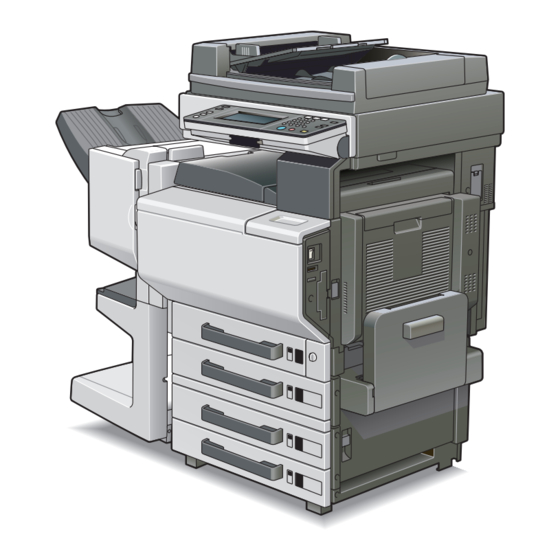
I.Outline of Installation Procedures for 4036 System
PC-101
When installing the machine and associated options as a system, follow the order shown on the upper.
Caution:
• For the detailed installation procedures for each option, follow the instructions given in the corresponding
Installation Manual and perform the procedures correctly.
• Once the Power Switch is turned ON, do not turn OFF it until the installation work has been completed.
• Make available collective manpower of an appropriate size for transporting the machine. (Machine mass:
100 kg/229 lb)
4036-7762-04
C350
INSTALLATION MANUAL
PC-201
Dehumidifier Heater 1C
Copier/Printer Machine
Electron System Options
MC-501
AD-501
FS-501
JS-601
DF-601
WT-501
PC-401
FS-601
PK-501/PK-4/
PK-131
OC-501
E-1
Applied Machine: C350
DK-501
✱ Electron System Options
EM-301
HD-501
EK-501
VI-501
IC-401
DT-105
VK-501
Advertisement
Table of Contents

Subscribe to Our Youtube Channel
Related Manuals for Konica Minolta C350


Summary of Contents for Konica Minolta C350
- Page 1 C350 INSTALLATION MANUAL KONICA MINOLTA Applied Machine: C350 BUSINESS TECHNOLOGIES, INC. < Important > Be sure to correctly follow the procedures in order as explained in this Installation Manual. If you do not follow the procedure in order, the image trouble may occur.
-
Page 2: Accessory Parts
II. Accessory parts III.Removing the Machine 1. Open the shipping carton and remove the IU car- Name Q’ty ton and machine carton. 1. Imaging unit (IU): Y,M,C,BK 2. Pull out the handles. 2. Power cord * 3. Cord clamp * 4. -
Page 3: Removing Protective Tape, Packing And Other Shipping Materials
IV.Removing Protective Tape, Packing and 4. Slide out the 1st drawer and remove protective tape and packing materials from the inside of the Other Shipping Materials drawer. 1. Remove protective tape from different parts of the machine. 5. Slide out the 2nd drawer and remove protective tape from the inside of the drawer. - Page 4 V.Installing the IU 4. Keeping the IU in the level position, insert it all the way as far as it will go. 1. Open the front door. Caution: 2. Pinch the IU release lever for Y and pull it down When inserting the IU, make sure that the leading forward.
- Page 5 VI.Charging Toner and Installing the Filter 5. Swing the fixing lever downward. 6. Load the toner bottle in position. Caution: (Make sure that the gear is on the rear side.) Toner does not come with the machine. Purchase toner bottles (of different colors) separately avail- able.
- Page 6 VII.Connecting the Power Cord and 5. Attach the cap A and B enclosed with the machine. Mounting the Accessories 1. Connect the power cord. 6. Attach the connector cover enclosed with the machine. 2. Remove the screw shown in the illustration. 3.
- Page 7 IX.Adjusting Touch Panel XI.Setting Gradation Adjust 1. Turn on the Power Switch. 1. Check that A3 or Ledger paper is loaded in the drawer. 2. Call “Touch Panel Adjust” to the screen. (To dis- play this function, press Stop → 0 → Stop → 3 on 2.
-
Page 8: Date And Time Setting
XII.Date & Time Setting 8. When the machine completes reading the test pattern, the “Gradation Adjust” screen will reap- pear. 9. Repeat steps from 4 through 7 to let the machine read the test pattern three times. 10.Touch “END.” 11.Touch “Fin. Time.” 1. -
Page 9: Unit Change
XIII.Serial # Input XIV.Unit Change Caution: This function allows the user to select the type of message that will appear when the replacement time arrives for each of the different units. 1. Display the Tech. Rep. Mode screen. (For details of how to display the Tech. Rep. Mode screen, see the service manual.) 2. -
Page 10: List Output
XV.List Output XVII.Adjusting Registration of Paper Source Options 1. Load the 1st drawer with A4L or Letter L paper. <PC-101, 401> 2. Display the Tech. Rep. Mode screen. 1. Display the Tech. Rep. Mode screen. (For details of how to display the Tech. Rep. (For details of how to display the Tech. - Page 11 <PC-201> <AD-501> 5. Display the Tech. Rep. Mode screen. 9. Display the Tech. Rep. Mode screen. (For details of how to display the Tech. Rep. (For details of how to display the Tech. Rep. Mode screen, see the service manual.) Mode screen, see the service manual.) 6.
- Page 12 XVIII.Installing the Drawer Cover If a paper source option is mounted, install the Drawer Cover that comes with the machine using the Mounting Screws that also come with the machine. E-12...
Need help?
Do you have a question about the C350 and is the answer not in the manual?
Questions and answers