Advertisement
Quick Links
Advertisement
Chapters

Subscribe to Our Youtube Channel
Related Manuals for Saadat ALBORZ B9


Summary of Contents for Saadat ALBORZ B9
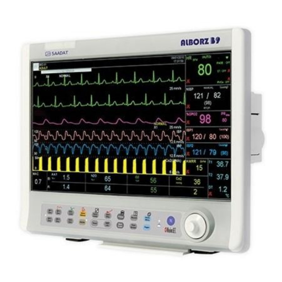
- Page 1 POOYANDEGAN RAH SAADAT OPERATOR’S MANUAL ALBORZ B9 Patient Monitor D00132-15...
- Page 2 POOYANDEGAN RAH SAADAT CO. No. 4, 1st East St., Ettehad Blvd., Damavand St., TEHRAN, IRAN. Post box: 1658916599 Tel: +98 21 77960719, +98 21 77962181 Fax:+98 21 77964239 Customer Services: Tel: +98 21 73098000, +98 21 77798910 Cell: +98 912 1977157...
- Page 3 Manual Purpose This manual provides the instructions necessary to operate bedside monitor in accordance with its intended use. It also describes all parameters and options that your monitor may have depending on the way it has been customized. Study of this manual is a prerequisite for proper operation and ensures patient and operator safety. If you have any question about the bedside, please contact our customer service.
- Page 4 Care & Cleaning (PM) Troubleshooting APPENDIX I Default Settings APPENDIX II Note: This guide describes all features and functions of SAADAT Co. patient monitors. Your monitor is highly customizable and may not have some of these features. Optional features are marked with*.
-
Page 5: Table Of Contents
Chapter 1: Introduction User Manual Chapter 1, Introduction 1.1 General Warnings....................2 1.2 Getting Start .......................6 1.3 General Information..................8 1.4 Display Screen ....................10 1.5 Buttons Function ....................13 1.6 Interfaces......................15 1.7 Built-in Battery....................18... -
Page 6: General Warnings
Chapter 1: Introduction User Manual 1.1 General Warnings Warning Patient monitor is intended for clinical monitoring application with operation only granted to appropriate medical staff. Warning Before use, carefully read this manual, directions for use of any accessories, all precautions, and all specifications. - Page 7 Chapter 1: Introduction User Manual Warning There could be hazard of electrical shock by opening the monitor casing. All servicing and future upgrading to this equipment must be carried out by personnel trained and authorized by manufacturer. Warning Equipment is not suitable for use in the presence of a flammable anaesthetic mixture with air or oxygen.
- Page 8 Chapter 1: Introduction User Manual Warning There will be some risks of polluting the environment associated with the disposal of the device and cables at the end of their useful lives. The device and accessories shall be disposed in accordance with national laws after their useful lives. Contact your municipality to check where you can safely dispose of old batteries.
- Page 9 Chapter 1: Introduction User Manual Warning Make sure that cables and accessories are not under tension during monitoring. Warning When using a defibrillator, parameters and signals will be temporarily interrupted until electroshock is finished.
-
Page 10: Getting Start
Chapter 1: Introduction User Manual 1.2 Getting Start Open the Package and Check Open the package and take out the monitor and accessories carefully. Keep the package for possible future transportation or storage. ■ Check for any mechanical damage. ■... - Page 11 Chapter 1: Introduction User Manual New patient information (For details, please refer to chapter Configuration, PATIENT INFORMATION) Patient mode (Adult/Neonate/ Pediatric) before NIBP measurement Alarm sound Alarm limits Zeroing before IBP measurement (For more information, see chapter IBP) Pulse oximetry (For more information, see chapter SpO2) RESP (For more information, see chapter RESP) NOTE: Check all the functions of modules that may be used and make sure that the monitor...
-
Page 12: General Information
Chapter 1: Introduction User Manual General Information Environment: Temperature Operating 5 to 40ºC Transport and Storage -25 to 60ºC Humidity Operating 20-90% Transport and Storage 10-100% Altitude -200 to 3000m Power Supply 100-240 VAC, 50/60Hz = 72W ① Power switch is located on the front panel ②... - Page 13 Chapter 1: Introduction User Manual Warning To verify proper function of indicators, they light when the system is powered on. Portable Patient Monitor will provide you with the following vital signs data: Heart Rate (HR), ST segment, PVCs/min, Arrhythmias, ECG waveforms Respiratory Rate (RR) , Respiration Waveform RESP SpO2...
-
Page 14: Display Screen
Chapter 1: Introduction User Manual 1.4 Display Screen Patient monitor has a color LED display. The patient Parameters, waveforms, alarm messages, bed number, date, system status and error messages are displayed on the screen. The screen is divided into four areas: Header Area; Waveform Area/ Menu Area; Parameter Area and Message Area (see figure 1-2). - Page 15 Chapter 1: Introduction User Manual Waveform / Menu Area : All waveforms can be displayed at the same time. The waveforms from top to bottom are: ECG, SpO2, IBP1, IBP2, EEG and RESP/CO2/Multi-gas. Gain, filter, lead and sweep of the ECG are displayed as well .The three dotted lines from top to bottom show the highest scale, cursor and lowest scale of IBP waveform.
- Page 16 Chapter 1: Introduction User Manual Warning Always verify the audible and visible alarms when monitor is powered on. Please refer to chapter Alarm for details. 1-12...
-
Page 17: Buttons Function
Chapter 1: Introduction User Manual 1.5 Buttons Function The monitor can be operated via the front panel buttons, rotary knob and touch screen* ① Power Press to power on or off the system. ② Freeze When in normal mode, press to freeze all waveforms on the screen. When in freeze mode, press to restore the waveform refreshing. - Page 18 Chapter 1: Introduction User Manual or larger), TEMP or " cursor at: ECG, NIBP, SpO2, IBP, BFA (for 12 RESP/CO2/Multi gas parameter area of the screen. When the cursor is located on a specific parameter area, you can change setting of that parameter as follows: 1.
-
Page 19: Interfaces
Chapter 1: Introduction User Manual Warning Before using the system on the patient, user must check the buttons function and make sure that it is in proper working condition as described above. 1.6 Interfaces ① Connector for ECG cable ② Connector for Spo2 Sensor ③... - Page 20 Chapter 1: Introduction User Manual The following sockets are located on the side panel . ■ Power Supply: 100-240 (VAC), 50/60 Hz (Socket ■ VGA SLAVE MONITOR (Socket Monitor interface for external standard VGA color monitor. Working mode: 800×600,256 colors Interface: D-sub 15 pins Pin 1.
- Page 21 Chapter 1: Introduction User Manual ■ (Jack ) Equipotential grounding terminal for connection to the hospital's grounding system. ■ Central Network Interface (Socket Data transmission between the central system and the bedside monitor Warning Patient monitor must be only connected to manufacturer's central system. Warning Use only the recommended central cable for connecting monitor to central system.
-
Page 22: Built-In Battery
Chapter 1: Introduction User Manual 1.7 Built-in Battery The patient monitor is equipped with a rechargeable battery. The battery will be automatically recharged when the monitor connects to the AC INPUT. When the AC INPUT is plugged in, turning the system on or off does not have any effect on charging process of the battery. - If sealed lead acid battery is used, it takes about 4 to 5 hours to charge the battery. - Page 23 Chapter 1: Introduction User Manual When the fuse is damaged, the system cannot run on the battery power and the battery symbol blinks on the screen. Warning The monitor will shut down automatically if the battery power is low. Before the battery is completely depleted, the alarm will sound and “LOW BATTERY"...
- Page 24 Chapter 2: Configuration User Manual Chapter 2, System Configuration 2-1 HOME WINDOW ....................2 2.2 SETUP .........................3 2.3 MODULE SETUP ....................7 2. 4 ABOUT......................10...
-
Page 25: Chapter 2, System Configuration
Chapter 2: Configuration User Manual 2-1 HOME WINDOW Patient care monitor has a flexible configuration. Press HOME/MENU key on the front panel or the rotary switch in Header area to enter HOME WINDOW and set configuration. Refer to the chapter TREND SIGMA, ALARM RECALL ALARM... -
Page 26: Setup
Chapter 2: Configuration User Manual 2.2 SETUP Choose "SETUP" in HOME WINDOW to call up the following menu: CALENDAR available options are "SOLAR" and "CHRISTIAN". DATE current date of monitoring. TIME current time of monitoring. BED NUMBER patient bed number (1-150). PATIENT CAT. - Page 27 Chapter 2: Configuration User Manual When Display Format is set to7 Traces, seven traces of ECG signal are displayed). You can monitor ECG (2 traces), CO2 (RESP) and SpO2 signals as well as all numeric P3 : parameters (special page for Rainbow parameters) (MAIN DISPLAY= PAGE 3 mode) You can monitor ECG signal (12 traces) and numeric parameters of P1.
- Page 28 Chapter 2: Configuration User Manual IBP) (MAIN DISPLAY= PAGE 6 mode) You can monitor ECG, SpO2, IBP1, IBP2 and RESP signals as well as numeric parameters HR, PVCs, ST, SpO2%, PR, IBP1,IBP2, NIBP,TEMP and RESP/CO2 (MAIN DISPLAY= PUMP PAGE mode). NOTE: To access PUMP Page, select SETUP from Home menu and then set MAIN DISPLAY to PUMP Page.
- Page 29 Chapter 2: Configuration User Manual new alarm level. 5-If “IBP Static Pressure” alarm occurs, SYS and DIA values will be removed and Mean value will be displayed in larger size. 6-IBP scales are adjusted automatically and “AUTO SCALE: ON” appears on IBP signals. Warning This page has specific usability and should be used only in the operating room.
-
Page 30: Module Setup
Chapter 2: Configuration User Manual CLEAR MEMORY To delete stored parameters in the system such as parameters saved in TREND, NIBP LIST, BFA TREND, ARR EVENT LIST and ALARM RECALL LIST. A message will appear on the screen for each of above items that asks you whether to clear that item or not. - Page 31 Chapter 2: Configuration User Manual For each change in parameters color, the following message will appear on the screen that asks you whether to change color or not. ARE YOU SURE TO CHANGE COLOR? Choose "MODULE VERSION" in MODULE SETUP window to access the following window in which you can see version of all modules.
- Page 32 Chapter 2: Configuration User Manual Choose “NETWORK SETUP” in MODULE SETUP window to call up the following window in which you can perform the Central system settings and see bedside and Central IP addresses, time of network connection and etc. SIGNAL QUALITY: The signal strength during WiFi connection of the bedside to the Central system.
-
Page 33: About
Chapter 2: Configuration User Manual Choose “NIBP VERSION” in MODULE SETUP window to call up the following window in which you can observe NIBP module information. 2. 4 ABOUT Choose "ABOUT" in HOME WINDOW to call up the following window in which you can observe the system and manufacturer information and displaying battery type. - Page 34 Chapter 3: Alarm User Manual Chapter 3, Alarm 3.1 ALARM.......................2 3.2 Alarm Categories ....................3 3.2.1 Physiological alarms ..................3 3.2.2 Technical alarms ..................3 3.2.3 Prompt messages ..................3 3.3 Alarm Modes ......................3 3.3.1 Alarm Level and Setup ................3 3.3.2 Alarm Modes ....................4 3.4 Alarm Causes......................5 3.5 Alarm Silence Button Function ................5 3.6 Parameter Alarm ....................6...
-
Page 35: Chapter 3, Alarm
Chapter 3: Alarm User Manual 3.1 ALARM Pick "ALARM" in HOME MENU to call up the following window: ■ ALARMS ON/OFF Pick "ON" to enable the alarm functions. Pick "OFF" to disable the alarm functions such as audio alarm, parameters blinking and alarm light indicator. -
Page 36: Alarm Categories
Chapter 3: Alarm User Manual This chapter gives general information about alarm and related functions. Warning Always verify the audible and visible alarms when monitor is powered on. 3.2 Alarm Categories Alarms can be classified into three categories: Physiological, Technical and Prompt messages. 3.2.1 Physiological alarms Physiological alarms also called patient status alarms are triggered by a parameter value that violates adjusted alarm limits or an abnormal patient condition. -
Page 37: Alarm Modes
Chapter 3: Alarm User Manual 3.3.2 Alarm Modes Alarm messages, LEDs and sounds are designed in such a manner that can be recognizable by the operator from a distance of 1 m. Display Screen When an alarm is triggered by a parameter, the parameter value will blink on the screen and alarm message with regard to its level will be displayed in different backgrounds. -
Page 38: Alarm Causes
Chapter 3: Alarm User Manual NOTE: When alarms of different levels occur at the same time, the alarm LED prompts the alarm of the highest level (red color) and the other alarms are displayed alternately in a background color corresponding to their levels. NOTE: If two or more alarms of the same level occur simultaneously, the alarm messages will be displayed alternately. -
Page 39: Parameter Alarm
Chapter 3: Alarm User Manual button, the alarm suspension status will be ended and the normal alarm status resumed immediately. 3.6 Parameter Alarm Alarm setting of each parameter can be found in its specific window. You can observe and set the alarm limits and alarm features of each parameter in its specific window. - Page 40 Chapter 4: PATIENT INFORMATION User Manual Chapter 4, PATIENT INFORMATION Choose "PATIENT INFORMATION" in HOME WINDOW to call up the following window: Press "NEW" to enter new patient information. The below confirmation message will appear. ARE YOU SURE TO CLEAR ALL DATA? If you select YES, ARR LIST, NIBP LIST, TREND and BFA TREND will be cleared and PATIENT CAT will be set to ADULT mode.
- Page 41 PATIENT INFORMATION User Manual Press "EDIT" to edit the previous patient information. Pick an item to call up the following window in which you can input data: NAME Patient name (length: 18 characters) PATIENT ID Hospital ID for patient (length: 18 characters) BIRTH DATE Date of the birth GENDER...
- Page 42 Chapter 5: ECG Monitoring User Manual Chapter 5, ECG Monitoring 5.1 GENERAL..........................2 5.2 Patient Preparation......................... 4 5-3 ECG Lead Wire Placement ....................5 Electrode placement for 3-Wire cable ..................6 Electrode placement for 5-Wire cable ..................7 Electrode placement for 10-Wire cable ..................9 5.4 ECG WINDOW ........................
-
Page 43: General
Chapter 5: ECG Monitoring User Manual 5.1 GENERAL Monitoring the ECG produces a continuous waveform of the patient's cardiac electric activity for an accurate assessment of his current physiological state. The process of depolarization and repolarization of the myocardium generates electric potential that are sensed by ECG electrodes on the skin. - Page 44 Chapter 5: ECG Monitoring User Manual Warning Interference from a non-grounded instrument near the patient and/or ESU (Electro Surgical Unit) interference can cause the waveform inaccuracy. Warning Select patient mode carefully, because QRS detection’s thresholds and algorithms are working different in Adult and Neonate modes.
-
Page 45: Patient Preparation
Chapter 5: ECG Monitoring User Manual 5.2 Patient Preparation 1. Prepare the patient's skin prior to electrode placement. ■ The skin is a poor conductor of electricity, therefore preparation of the patient's skin is important to facilitate good electrode contact to skin. ■... -
Page 46: Ecg Lead Wire Placement
Chapter 5: ECG Monitoring User Manual 5-3 ECG Lead Wire Placement The ECG patient cable consists of 2 parts: The trunk cable that is connected to the monitor and the patient lead wires that are connected to the patient . Available cable types and the various methods of lead placement are described in following part Electrode’s locations for 3-wire ECG Cable... -
Page 47: Electrode Placement For 3-Wire Cable
Chapter 5: ECG Monitoring User Manual Electrode placement for 3-Wire cable Right Arm (RA): red electrode, be placed near the right shoulder, directly below the clavicle. Left Arm (LA): yellow electrode, be placed near the left shoulder, directly below the clavicle. Left Leg (LL): green electrode, be placed on the left hypogastrium. -
Page 48: Electrode Placement For 5-Wire Cable
Chapter 5: ECG Monitoring User Manual Electrode placement for 5-Wire cable Right Arm (RA): red electrode, be placed near the right shoulder, directly below the clavicle. Left Arm (LA): yellow electrode, be placed near the left shoulder, directly below the clavicle. Chest (C): white electrode, be placed on the chest as illustrated in figure 4-2 Right Leg (RL): black electrode, be placed on the right hypogastrium. - Page 49 Chapter 5: ECG Monitoring User Manual ECG Leads Depending on cable’s type (3-WIRE or 5-WIRE), you can choose different leads I, II, III, aVR, aVL, aVF and V.
-
Page 50: Electrode Placement For 10-Wire Cable
Chapter 5: ECG Monitoring User Manual Electrode placement for 10-Wire cable Right Arm (RA): red electrode, be placed near the right shoulder, directly below the clavicle. Left Arm (LA): yellow electrode, be placed near the left shoulder, directly below the clavicle. Right Leg (RL): black electrode, be placed on the right hypogastrium. - Page 51 Chapter 5: ECG Monitoring User Manual Warning Unplug the ECG cable from the socket, the error message "ECG NO CABLE" should be displayed on screen. Warning Before monitoring, check ECG cable safety and replace cables that are damaged, scratched, torn, or their distorted lead-wires. Warning Pay attention that ECG cable is not subjected to tension during connection.
- Page 52 Chapter 5: ECG Monitoring User Manual Warning Line Isolation Monitor (LIM) fluctuations may resemble actual cardiac waveforms and thus activate heart rate alarms. Such fluctuations may be minimized by proper electrode and cable placement, as specified in this manual. Warning When using Electro surgery equipment, leads should be placed in the furthest possible distance from Electro surgery electrodes and its grounding plate to avoid burning.
-
Page 53: Ecg Window
Chapter 5: ECG Monitoring User Manual 5.4 ECG WINDOW The following items can be monitored in ECG parameter window: ECG PARAMETER WINDOW NOTE: In the absence of a proper signal, the monitor is not able to count the heart rate and instead of the HR number, the symbol (-? -) is displayed in the ECG window. - Page 54 Chapter 5: ECG Monitoring User Manual Pick ECG by clicking on parameter, the following menu will pop up: ■ ECG LEAD: by pressing ECG LEAD, the following menu will pop up: ECG TRACE: You can choose the following leads for traces 1 to 4: "І"...
- Page 55 Chapter 5: ECG Monitoring User Manual NOTE: You can choose aVR, aVL, aVF and V just when ECG is in 5-WIRE mode. The leads V2, V3, V4, V5 and V6 can be observed only in 12-lead ECG mode. NOTE: Main lead is selectable in ECG menu. In pages that more than one trace of ECG signal is displayed, the first trace is related to the main lead.
- Page 56 Chapter 5: ECG Monitoring User Manual CABLE TYPE To adjust ECG measurement mode to "3 WIRES", "5 WIRES “and "10 WIRES". DISPLAY FORMAT In case of choosing "3 WIRES" for CABLE TYPE: only Cascade mode is applicable for DISPLAY FORMAT. In case of choosing "5 WIRES"...
- Page 57 To calculate HR value average, the values are sent per second to averaging section and any change based on user setting is made in output data. - Response time of Saadat monitor to HR change with regard to different HR averages is as follows: Response Time HR Avg.= 4s...
- Page 58 Chapter 5: ECG Monitoring User Manual The above results are for lead II as reference lead. - When HR High (for instance when HR reaches to 120 bpm) happens, the alarm is activated in 6 seconds. (by setting HR alarm limits between 60 bpm and 100 bpm). - In case of cardiac Asystol, the alarm is activated in 10 seconds (from 80 bpm to 0 bpm).
- Page 59 If “HR SOURCE” is set to any module and cable of the module is not connected to the system, HR value will not be displayed NOTE: IBP3 and IBP4 can only be active in the ALBORZ B9 system. NOTE: Calculating HR from IBP signal is possible just from ART, PAP, RVP, LVP and IBP labelled signal.
- Page 60 Chapter 5: ECG Monitoring User Manual ■ BEAT VOLUME Available options for are between “1” to “7” and “OFF”; "OFF" indicates silence, while 7 indicates maximum volume. ■ PACE DETECT "ON" for patient with pacemaker," OFF" for patient without pacemaker. When PACE DETECT is "ON", the ECG monitoring system detects and rejects pacemaker-generated signals from ECG signal so that they will be ignored in calculating the heart rate.
- Page 61 Chapter 5: ECG Monitoring User Manual Warning For patients with pacemaker, PACE DETECT must be switched "ON", otherwise, the pace pulses may affect HR counting and result in low precision of HR value. Warning For the patients with pacemaker, the monitor may continue to count the pacemaker rate as heart rate during the occurrence of cardiac arrest or some arrhythmias.
- Page 62 Chapter 5: ECG Monitoring User Manual ■ ALARM RECORD See the chapter “RECORDING”. ■ ARR ANALYSIS Pick "ARR ANALYSIS" in ECG WINDOW to call up the window for arrhythmia analysis setting. This monitor is able to detect up to 13 types of arrhythmia. Refer to the chapter “ARR MONITORING”...
-
Page 63: Ecg Output
Chapter 5: ECG Monitoring User Manual 5.5 ECG OUTPUT An analog ECG signal is obtained from ECG OUTPUT connector located on the system’s power plate. This signal is similar to the displayed ECG signal on the monitor and can be used as an input for some devices such as Electro shock (Defibrillator). -
Page 64: Ecg Alarms
Chapter 5: ECG Monitoring User Manual 5.6 ECG Alarms a) Physiological alarms The auditory alarm sounds when: 1. The heart rate violates the adjusted alarm limits, and/or, 2. The ECG ASYSTOLE occurs. ALARM SITUATION VISUAL PROMPTS AUDIO SOUND HR HIGH Heart rate violates ●HR value blinks. -
Page 65: B) Technical Alarms
Chapter 5: ECG Monitoring User Manual b) Technical alarms Alarm Cause Solution Explanation Alarm level 3- the message is displayed in cyan background. By ECG cable is not ECG NO pressing ALARM SILENCE, connected to the Connect ECG cable CABLE background becomes gray and system alarm is disabled and ignores this... - Page 66 Chapter 5: ECG Monitoring User Manual Alarm level 2- the message is LA or other leads are displayed in yellow background. By not properly Make sure that all electrodes and pressing ALARM SILENCE, CHECK LA connected when ECG patient cable are properly background becomes gray and the OR ALL lead is II for 3wire...
- Page 67 Chapter 6: Arrhythmia Monitoring User Manual Chapter6, Arrhythmia Monitoring 6.1 GENERAL......................2 6.2 ARR ANALYSIS WINDOW ................5 6.3 ARRHYTHMIA ALARMS................11...
- Page 68 Chapter 6: Arrhythmia Monitoring User Manual 6.1 GENERAL Arrhythmia means any disturbance or irregularity of cardiac rhythm. Stability of the cardiac rhythm is essential for sufficient pumping function of the heart and adequate cardiac output. Maintaining adequate cardiac output is vital for organ perfusion and survival. Arrhythmia can cause a decrease in cardiac output.
- Page 69 Chapter 6: Arrhythmia Monitoring User Manual Arrhythmia detection algorithm principle The arrhythmia algorithm is based on template matching. (A template is a group of beats matching the same morphology). The algorithm detects QRS complexes, generates QRS templates and performs beat labelling. This algorithm is divided into three parts: detector, classifier and labelling.
- Page 70 Chapter 6: Arrhythmia Monitoring User Manual The following table describes available beat classifications: Arrhythmia Event and Beat Classification ECG ASYSTOLE 5 seconds pass without the detection of valid QRS complex. Ventricular Fibrillation: The monitor identifies a sinusoidal waveform with fibrillation characteristics. (Certain ventricular tachycardias have sinusoidal waveforms closely resembling those VFIB ARRHYTHMIA of ventricular fibrillation.
- Page 71 Chapter 6: Arrhythmia Monitoring User Manual Figure 14-1 PVC value in ECG parameters area NOTE: When PACE is turned ON, for patient with pacemaker, the system will not detect the arrhythmia relating to premature ventricular beats. 6.2 ARR ANALYSIS WINDOW Pick "ARR ANALYSIS“in the ECG WINDOW to call up the following menu: ECG/ARR ANALYSIS WINDOW ■...
- Page 72 Chapter 6: Arrhythmia Monitoring User Manual ECG/ARR ANALYSIS /ARR SETUP WINDOW ARR SETUP Window allows you to set the arrhythmia monitoring based on the patient needs. The arrhythmia events and relevant settings are displayed in two columns. Unrelated settings to a specific arrhythmia are shown by a dash and the settings which could not be changed for a specific arrhythmia are dimmed.
- Page 73 Chapter 6: Arrhythmia Monitoring User Manual ● RATE With count, you can determine the point at which an event call is triggered. You cannot modify the rate for “ASYSTOLE”, ”VFIB”, ”COUPLET”, ”BIGEMINY”, ”TRIGEMINY”, “PAUS”, “ AFIB” and “FREQUENT PVCs” . “RUN”...
- Page 74 Chapter 6: Arrhythmia Monitoring User Manual ■ ARR EVENT RECALL Pick " ARR EVENT RECALL” in ARR ANALYSIS WINDOW to call up the following menu: ECG/ARR ANALYSIS / ARR EVENT RECALL WINDOW You can review any stored arrhythmia event (maximum 150 events) in this window. NOTE: If an arrhythmia event occurs and persists, it will be stored in ECG/ARR ANALISIS/ARR EVENT RECALL WINDOW for one time, but if this event is...
- Page 75 Chapter 6: Arrhythmia Monitoring User Manual ■ To see detail information of arrhythmia event: Pick the third left item to call up the following window ECG/ARR ANALYSIS /ARR EVENT RECALL/WAVE WINDOW In this window, waveform and time of selected arrhythmia event as well as other vital sign parameters values at the event time are displayed.
- Page 76 Chapter 6: Arrhythmia Monitoring User Manual NOTE: You can do relearn procedure by selecting <ST RELEARN> in ECG/ST ANALYSIS window. NOTE: In most situations the learning phase takes about 20 seconds. NOTE: If the monitor couldn’t find 6 matching beats after 20 seconds, the relearn procedure continues and the “RELEARN”...
- Page 77 Chapter 6: Arrhythmia Monitoring User Manual 6.3 ARRHYTHMIA ALARMS ARRHYTHMIA ALARMS ALARM VISUAL PROMPTS AUDIO SOUND SITUATION ●The alarm indicator flashes. ●The alarm message is displayed ASYSTOLE 5 seconds pass without the detection of Activated ARRHYTHMIA in a background corresponding to valid QRS complex.
- Page 78 Chapter 6: Arrhythmia Monitoring User Manual ●The alarm indicator flashes. Activated Ventricular Trigeminy: Sequence of ●The alarm message is displayed TRIGEMINY (If ARR MONITOR beats with the pattern : normal, ARRHYTHMIA in a background corresponding to and Alarm normal, PVC, normal, normal, PVC its level.
- Page 79 Chapter 7: ST Monitoring User Manual Chapter 7, ST Monitoring 7.1 GENERAL......................2 7.2 ST ANALYSIS WINDOW ................4 7.3 ST Alarm Messages....................8...
- Page 80 Chapter 7: ST Monitoring User Manual 7.1 GENERAL ST segment deviation is defined as the displacement above or below the isoelectric level. The measurement of deviation compares the isoelectric point to the ST measurement point. The isoelectric point defines the point of zero voltage (no electrical activity) with a default position of 80ms from R wave as 0msec in the horizontal (time) axis.
- Page 81 Chapter 7: ST Monitoring User Manual NOTE: ST monitoring is available for adult and pediatric patient and it is not recommended for neonates. NOTE: If there are not at least 5 normal complexes in the last 50 beats of ECG signal, the ST value will not be displayed.
- Page 82 Chapter 7: ST Monitoring User Manual 7.2 ST ANALYSIS WINDOW Pick "ST ANALYSIS “in the ECG WINDOW to call up the following menu: ECG/ ST ANALYSIS WINDOW ■ ST ANALYSIS Pick this item to enable or disable ST monitoring. The default is OFF. When the ST monitoring is disabled “ST OFF”...
- Page 83 Chapter 7: ST Monitoring User Manual During the learning procedure the following actions will be taken: Average stored dominant QRS complex currently displayed on the DEFAULT POINT window is deleted. New dominant QRS complex template is identified. New complex is displayed on DEFAULT POINT window. NOTE: You can do relearn procedure by selecting <ARR RELEARN>...
- Page 84 Chapter 7: ST Monitoring User Manual ECG/ST ANALYSIS/DEFAULT WINDOW As shown above, the DEFAULT POINT WINDOW shows the dominant QRS complex template. Two vertical lines indicate the positions of the ISO and ST points. ISO: It is the base point, used to indicate the baseline point of the ST analysis. The default is 80ms.
- Page 85 Chapter 7: ST Monitoring User Manual NOTE: If pace is ON (for patient with pacemaker) or while learning procedure, there is no waveform in DEFAULT POINT Window and you can see just ISO and ST lines. In this condition, ST value will not be measured. NOTE: A red vertical marker with “CHG”...
- Page 86 Chapter 7: ST Monitoring User Manual 7.3 ST Alarm Messages The alarm occurs when ST value exceeds the adjusted alarm limits: Alarm Situation Visual prompt Audio sound ●ST value blinks. ●The alarm indicator ST segment value violates flashes. Activated ST HIGH adjusted high limit ●...
- Page 87 Chapter 8: RESP Monitoring User Manual Chapter 8, RESP Monitoring 8.1 GENERAL......................2 8.2 RESP WINDOW ....................3 8.3 RESP Alarm Messages ..................5 a) Physiological alarms ..................5 b) Technical alarms....................5...
- Page 88 Chapter 8: RESP Monitoring User Manual 8.1 GENERAL The monitor measures respiration rate from the amount of thoracic impedance between two ECG electrodes RA-LL or RA-LA, corresponding to ECG Lead II and ECG Lead I respectively. The change of impedance between the two electrodes, (due to the thoracic movement), produces a respiratory waveform on the screen.
- Page 89 Chapter 8: RESP Monitoring User Manual 8.2 RESP WINDOW If RESP is used for respiration assessment, RESP parameter window will be as below: Pick RESP to call up the following menu: ■ RESP LEAD Available options for RESP LEAD are "RA-LA" and "RA-LL" ■...
- Page 90 Chapter 8: RESP Monitoring User Manual ■ RR ALARM Pick "ON" to enable RESP alarm functions such as parameters blinking, audio alarm and light indicator. Pick "OFF" to disable the alarm functions, and there will be a" "symbol in the Parameter Area. ■...
- Page 91 Chapter 8: RESP Monitoring User Manual 8.3 RESP Alarm Messages a) Physiological alarms The alarm is activated when the respiration rate exceeds the adjusted alarm limits. Physiological alarms AUDIO ALARM SITUATION VISUAL PROMPTS SOUND ●RESP value blinks Respiration rate violates ●The alarm indicator flashes.
- Page 92 Chapter 8: RESP Monitoring User Manual Technical alarms Alarm Cause Solution Explanation Alarm level 3- the message is displayed in cyan background. By Make sure that all pressing ALARM SILENCE, RESP CHECK The RESP leads are not electrodes, lead are background becomes gray and the LEADS properly connected.
- Page 93 Chapter 9: SpO2 & Rainbow Parameters Monitoring User Manual Chapter 9, SPO2 and Rainbow Parameters Monitoring 9.1 GENERAL......................2 9.2 SPO2 WINDOW ....................14 9.3 SpO2 and Rainbow Parameters Alarm Messages ........18 a) Physiological alarms ..................18 b) Technical alarms.....................20 c) Messages......................24...
-
Page 94: General
Chapter 9: SpO2 & Rainbow Parameters Monitoring User Manual 9.1 GENERAL SpO2 Rainbow module is the only technology which measures multiple blood parameters as well as common pulse oximetry parameters (SpO2 and Pulse Rate) in a continuous and non-invasive method that traditionally measured through the invasive and time-consuming methods. This module is designed by Masimo Company and submitted to its approved companies. - Page 95 Chapter 9: SpO2 & Rainbow Parameters Monitoring User Manual Pulse rate PR indicates the Heart Rate per minute which SpO2 module extracts from the pulse oximetry signal. Perfusion Index Perfusion index (PI) indicates arterial pulse signal strength as a ratio of pulsatile blood flow to the non-pulsatile blood.
- Page 96 Chapter 9: SpO2 & Rainbow Parameters Monitoring User Manual measurement is ml/dL (milliliters of oxygen per deciliter of blood). SpCO This parameter indicates the level of carbon monoxide concentration in arterial blood. It is expressed as a percentage of hemoglobin bound with carbon monoxide. SpMet This parameter indicates the level of methemoglobin concentration in arterial blood.
- Page 97 Chapter 9: SpO2 & Rainbow Parameters Monitoring User Manual Operating Principals 1.Oxyhemoglobin (oxygenated blood), deoxyhemoglobin (non-oxhygenated blood), carboxyhemoglobin (blood with carbon monoxide content), methemoglobin (blood with oxidized hemoglobin) and blood plasma constituents differ in their absorption of visible and infrared light (using spectrophotometry).
- Page 98 Chapter 9: SpO2 & Rainbow Parameters Monitoring User Manual (detector). Signal data is obtained by passing various visible and infrared lights (LED's, 500 to 1400 nm) through a capillary bed (for example, a fingertip, a hand, a foot) and measuring changes in light absorption during the blood pulsatile cycle.
- Page 99 Chapter 9: SpO2 & Rainbow Parameters Monitoring User Manual NOTE: For more information about Masimo Rainbow module. Also, For Masimo patent information, please refer to the following address: “www.masimo.com/patents.htm” NOTE: A pulse oximetry is an early warning device. Use lab co-oximeter to understand the patient's condition completely.
- Page 100 Chapter 9: SpO2 & Rainbow Parameters Monitoring User Manual Warning Do not place the accessories in any position that might cause it to fall on the patient. Warning Do not immerse sensor and patient cable completely in water, solvents, or cleaning solutions because the sensor and patient cable are not waterproof.
- Page 101 Chapter 9: SpO2 & Rainbow Parameters Monitoring User Manual Warning The pulse co-oximeter is not an apnea monitor. Warning The pulse co-oximeter should not be used for arrhythmia analysis. Warning Pulse oximetry can overestimate the SpO2 value in the presence of Hb-CO, Met-Hb or dye dilution chemicals.
- Page 102 Chapter 9: SpO2 & Rainbow Parameters Monitoring User Manual NOTE: Do not perform SpO2 and NIBP measuring in same arm simultaneously; because obstruction of blood flow during NIBP measuring may adversely affect the SpO2 value. Measurement range of SpO2 and PR parameters in SpO2 MASIMO module is as follows: Measurement Parameter Range...
- Page 103 Chapter 9: SpO2 & Rainbow Parameters Monitoring User Manual SpO2 measurement: 1.Turn on the monitor. 2.Attach the sensor to the appropriate site of the patient finger 3.Plug the connector of the sensor extension cable into the SpO2 socket on the left side of the device.
- Page 104 Chapter 9: SpO2 & Rainbow Parameters Monitoring User Manual ● Venous pulsations ● Cabling entanglement or strangulation ● Placement of the sensor on an extremity that has a blood pressure cuff, arterial catheter, or intravascular line ● Do not use pulse co-oximeter during magnetic resonance imaging (MRI) or in an MRI environment.
- Page 105 Chapter 9: SpO2 & Rainbow Parameters Monitoring User Manual Caution If “SpO2 LOW PERFUSION” message is frequently displayed, find a better perfused monitoring site. In the interim, assess the patient and, if indicated, verify oxygenation status through other means. Warning Prolonged and continuous monitoring may increase jeopardy of unexpected change of dermal condition such as abnormal sensitivity, vesicle, repressive putrescence, and so on.
-
Page 106: Spo2 Window
Chapter 9: SpO2 & Rainbow Parameters Monitoring User Manual 9.2 SPO2 WINDOW The following items are displayed in SpO2 parameter window: SPO2 PARAMETER WINDOW SpO2 parameter window (special page for Rainbow parameters) is as follows: RAINBOW PARAMETERS WINDOW 9-14... - Page 107 Chapter 9: SpO2 & Rainbow Parameters Monitoring User Manual The SpO2 WINDOW is as follows: ■ AVERAGE TIME Available options are 2-4, 4-6, 8, 10, 12, 14 and 16. ■ SPO2 PLETH SWEEP Available options for SpO2 PLETH SWEEP are 12.5 mm/s and 25 mm/s. ■...
- Page 108 Chapter 9: SpO2 & Rainbow Parameters Monitoring User Manual MAX: Recognizing that some clinicians may want the absolute low perfusion performance (0.02%) all of the time and may be willing to sacrifice sensor off detection, Masimo provides a maximized sensitivity mode. This mode should be used for the sickest patients, where obtaining a reading is most difficult.
- Page 109 Chapter 9: SpO2 & Rainbow Parameters Monitoring User Manual Alarm limit of Rainbow parameters is as follows: Parameter Alarm Limit HIGH Alarm PI LOW Alarm +0.1 to 19.0 LOW Alarm 0.0 to PI HIGH Alarm -0.1 HIGH Alarm PVI LOW Alarm +1 to 99 LOW Alarm 1 to PVI HIGH Alarm -1 HIGH Alarm...
-
Page 110: Spo2 And Rainbow Parameters Alarm Messages
Chapter 9: SpO2 & Rainbow Parameters Monitoring User Manual 9.3 SpO2 and Rainbow Parameters Alarm Messages a) Physiological alarms The alarm occurs when SpO2 and PR values exceed the adjusted alarm limits. AUDIO ALARM SITUATION VISUAL PROMPTS SOUND ● SPO2 value blinks. ●... - Page 111 Chapter 9: SpO2 & Rainbow Parameters Monitoring User Manual ● PI value blinks. ● The alarm indicator flashes. PI violates adjusted low alarm PI LOW ● The alarm message is Activated limit displayed in a background corresponding to its level. Alarm Situation Visual alarm...
-
Page 112: B) Technical Alarms
Chapter 9: SpO2 & Rainbow Parameters Monitoring User Manual ● SpMet value blinks. ● The alarm indicator flashes SpMet violates adjusted low ● The alarm message is SpMet LOW Activated alarm limit displayed in a background corresponding to its level. ●... - Page 113 Chapter 9: SpO2 & Rainbow Parameters Monitoring User Manual message is displayed again, replace cable. Alarm level 3- the message is displayed in cyan background. By Make sure that SpO2 pressing ALARM SILENCE, SPO2 NO SpO2 Sensor is not fully inserted sensor is correctly background becomes gray and the SENSOR...
- Page 114 Chapter 9: SpO2 & Rainbow Parameters Monitoring User Manual background becomes gray and the alarm is disabled and ignores this fault. Alarm level 2- the message is When a single-patient-use sensor displayed in yellow background. SPO2 is used, the life of the adhesive Replace the adhesive By pressing ALARM SILENCE, REPLACE AD...
- Page 115 Chapter 9: SpO2 & Rainbow Parameters Monitoring User Manual Alarm level 2- the message is Check the sensor displayed in yellow background. SPO2 SENSOR connection and, if By pressing ALARM SILENCE, The sensor connection to the CHECK necessary, replace the background becomes gray and the system is not correct CONNECTION...
-
Page 116: C) Messages
Chapter 9: SpO2 & Rainbow Parameters Monitoring User Manual excessive motion or other signal application. background becomes gray and the interference. 3-Change the sensor alarm is disabled and ignores this site. fault. SPO2 LOW 1-Assess the patient. Alarm level 3- the message is SpMet measurement does not SPMET 2-Check the sensor and... - Page 117 Chapter 9: SpO2 & Rainbow Parameters Monitoring User Manual If instrument fails to display within 30 seconds, disconnect and Instrument is searching for In this condition SPO2 parameter is SPO2 SEARCH reconnect. If pulse pulse. displayed blank. search continues, move sensor to better perfused site.
- Page 118 Chapter 10: NIBP Monitoring User Manual Chapter 10, NIBP Monitoring 10.1 GENERAL......................2 10.2 NIBP WINDOW....................8 10.3 NIBP Alarm Messages...................12 a) Physiological alarms ..................12 b) Technical alarms.....................13 c) Messages......................15 10.4 Frequently Asked Questions .................16 10-1...
-
Page 119: General
IBP pressure. It should be noted that in patients with high pressure, the systolic and diastolic values may have lower accuracy than those with normal pressure. This restriction is not specific to the SAADAT monitor and includes all monitors that use an oscillometric method to measure NIBP. - Page 120 A set of comprehensive and extensive internal and clinical tests was performed on individuals using the SAADAT NIBP Module and the results were compared with IBP measurements and the measurements taken by approved devices in the market. The results of these tests represent reliability of the SAADAT NIBP module.
- Page 121 Chapter 10: NIBP Monitoring User Manual 3. Connect the cuff to the air hose. 4. Check whether the patient mode is appropriately selected. To change the patient mode, choose from the HOME/SETUP WINDOW. In this section, there are three modes to PATIENT CAT.
- Page 122 Chapter 10: NIBP Monitoring User Manual NOTE: ■ NIBP measurements can be performed adjacent to electrosurgical unit. Warning Do not apply the cuff to a limb that has an intravenous infusion or catheter in place. This could cause tissue damage around the catheter when infusion is slowed or blocked during cuff inflation.
- Page 123 Chapter 10: NIBP Monitoring User Manual circulatory system failure. Thus examine the limb wearing cuff regularly. Warning NIBP measurement may not be appropriate for some patients especially the patients with arrhythmia, preeclampsia, specific cardiovascular diseases and pregnant women. Warning Please take into account the following items as you perform blood pressure measurement particularly in patients with hypertension.
- Page 124 Chapter 10: NIBP Monitoring User Manual Warning Prolonged non-invasive blood pressure measurements in STAT mode may be associated with ischemia, neuropathy or dermal injuries in the limb wearing the cuff. NOTE: If you are in doubt about the accuracy of any measurement(s), check the patient's vital signs by an alternative method before checking the functionality of the monitor.
-
Page 125: Nibp Window
Chapter 10: NIBP Monitoring User Manual 10.2 NIBP WINDOW NIBP PARAMETER WINDOW In pages which IBP parameter is not displayed (RESP mode), PR value will also be displayed in this window. NIBP PARAMETER WINDOW (Pages without IBP) Heart rate measured by NIBP module is in the range of 40 to 240 BPM. NIBP window is as follows: 10-8... - Page 126 Chapter 10: NIBP Monitoring User Manual ■ NIBP UNIT Pick this item to adjust measurement unit. (Options: mmHg or KPa) ■ ALARM LEVEL Selectable between 1 and 2. Level 1 represents the most serious case. ■ NIBP ALARM Pick "ON" to enable NIBP alarm functions such as parameters blinking, audio alarm and light indicator.
- Page 127 Chapter 10: NIBP Monitoring User Manual measurement is performed up to ten times within 5 minutes with 30s interval between measurements. If an error occurs, NIBP measurement is suspended. <MODULE START> To start measurement <MODULE STOP> To stop measurement <MODULE RESET> To set maximum inflation pressure of cuff to 150 mmHg for adult, 140 mmHg for pediatric and 85 mmHg for neonate.
- Page 128 Chapter 10: NIBP Monitoring User Manual ■ MODULE CHECK Select this item to open the respective menu after 5 seconds delay.Available options are "NIBP MANOMETER","NIBP LEAKAGE","MODULE SELF TEST" and "MODULE STOP". NOTE: Below tests must only be done by trained and authorized personnel. ■...
-
Page 129: Nibp Alarm Messages
Chapter 10: NIBP Monitoring User Manual 10.3 NIBP Alarm Messages a) Physiological alarms The alarm occurs when the pressure (SYS. DIA or MAP) value exceeds the alarm limits. NIBP ALARMS AUDIO ALARM SITUATION VISUAL PROMPTS SOUND ● SYS value blinks ●The alarm indicator flashes. -
Page 130: B) Technical Alarms
Chapter 10: NIBP Monitoring User Manual b) Technical alarms NIBP ALARMS Alarm Cause Solution Explanation Alarm level is set in NIBP Window. By pressing ALARM SELF-TEST SILENCE, the message NIBP hardware module failure FAILED background becomes gray and the alarm is disabled and ignores this fault. - Page 131 240 mmHg for pediatric Window. By pressing ALARM NIBP OVER and 145mmHg for neonate. SILENCE, the message PRESSURE (NIBP SAADAT: measured background becomes gray and the SENSED pressure exceeds safe software alarm is disabled and ignores this limit, 290 mmHg for adult and fault.
-
Page 132: C) Messages
Chapter 10: NIBP Monitoring User Manual Alarm level is set in NIBP Window. By pressing ALARM Error occurs in pump, A/D SYSTEM SILENCE, the message sampling, pressure transducer or FAILURE background becomes gray and the software. alarm is disabled and ignores this fault. -
Page 133: Frequently Asked Questions
Chapter 10: NIBP Monitoring User Manual 10.4 Frequently Asked Questions 1- Why does the monitor sometimes reinflate the NIBP cuff? The monitor will typically pump to an initial pressure of 150 mmHg or 30 mmHg higher than the last systolic reading in subsequent measurements. If the patient’s systolic pressure is higher than this initial pressure, reinflation will occur. - Page 134 Chapter 10: NIBP Monitoring User Manual Contact the manufacturer. 8- The module is not able to measure the patient's pressure and the question mark (?) appears: Choosing measurement mode: Is the measurement mode correctly selected? If you have used the neonate mode for pediatric or adult, there's a chance that you will not be able to measure it.
- Page 135 Chapter 11: TEMP Monitoring User Manual Chapter 11, TEMP Monitoring 11.1 GENERAL......................2 11.2 TEMP WINDOW.....................3 11.3 TEMP ALARM MESSAGES .................5 11-1...
- Page 136 Chapter 11: TEMP Monitoring User Manual 11.1 GENERAL Measurement of patient temperature is accomplished by processing the signal from a probe containing temperature dependent resistor called thermistor .Value of this resistor is measured by the monitor continuously and displayed on screen. Patient monitor has two different kinds of temperature probe, a probe for esophageal /rectal temperature measurement and other for skin temperature measurement.
- Page 137 Chapter 11: TEMP Monitoring User Manual NOTE: Please be noted that the metal side of probe should be used for making measurements. WARNING Using ESU with temperature measurement simultaneously may cause patient burn. If possible, remove the probe from patient contact before activating the surgical unit or other RF source.
- Page 138 Chapter 11: TEMP Monitoring User Manual The TEMP WINDOW is as follows: ■ UNIT Pick this item to set measurement unit. (options: ºC or ºF) ■ ALARM LEVEL Selectable between 1 and 2. Level 1 represents the most serious case. ■...
- Page 139 Chapter 11: TEMP Monitoring User Manual 11.3 TEMP ALARM MESSAGES The alarm occurs when the alarm function is "ON" and the temperature exceeds the adjusted alarm limits. AUDIO ALARM SITUATION VISUAL PROMPTS SOUND ● T1 value blinks ●The alarm indicator flashes. The temperature (T1) violates Activated T1 HIGH...
- Page 140 Chapter 12: IBP Monitoring User Manual Chapter 12, IBP Monitoring 12.1 GENERAL......................2 12.2 IBP WINDOW....................4 12.3 IBP Alarm Messages..................15 a) Physiological alarms ..................15 b) Technical alarms.....................16 c) Messages......................17 12-1...
-
Page 141: Chapter 12, Ibp Monitoring
Chapter 12: IBP Monitoring User Manual 12.1 GENERAL Specification: Displaying and measuring range (for all labels) -50~300(mmHg) Alarm ranges -50~300(mmHg) -50~300(mmHg) -50~300(mmHg) -50~120(mmHg) -50~100(mmHg) -50~100(mmHg) -50~100(mmHg) -50~100(mmHg) -40~100(mmHg) Resolution 1 (mmHg) Accuracy +2 % or 2mmHg each one is greater IBP stands for Invasive Blood Pressure. - Page 142 Chapter 12: IBP Monitoring User Manual Warning Do not use the sterile supplied IBP transducers if the packaging or the transducer is damaged and return them to the vendor. Warning Verify transducer cables fault detection prior to the start of monitoring phase. Unplug the transducer of the channel 1 from the socket, the screen will display the error message "IBP1 NO SENSOR"...
-
Page 143: Ibp Window
Chapter 12: IBP Monitoring User Manual (1) Normal Salin with Heparin (2) Drip Chamber (3) Valve (4) Distal End to Patient (5) 3-way Stopcock (6) Pressure Transducer (7) Pressure Transducer Interface Cable 12.2 IBP WINDOW The following items are displayed in IBP parameter window. The IBP WINDOW is as follows: 12-4... - Page 144 DISPLAY >PUMP PAGE For more information, see different page configurations in the configuration chapter. Note: IBP3 and IBP4 are only active in the ALBORZ B9 system. ■ IBP1/IBP2/IBP3/IBP4 LABEL Suitable label should be selected, regarding the place of measurement. The available...
- Page 145 Chapter 12: IBP Monitoring User Manual Warning When using PUMP PAGE, the IBP label must be set to CVP. ■ IBP SWEEP Available options for IBP SWEEP are 3,6,12.5 and 25mm/s. ■ IBP GRID Select "ON" to divide each IBP signal to 5 parts with white dot lines. ■...
- Page 146 Chapter 12: IBP Monitoring User Manual ■ ALARM Pick "IBP ALARM" in IBP WINDOW to call up the following menu: ■ IBP1/IBP2/IBP3/IBP4 ALARM Pick "ON" to enable alarm functions such as parameters blinking, audio alarm and light indicator. Pick "OFF" to disable the alarm functions and there will be a " "...
- Page 147 Chapter 12: IBP Monitoring User Manual NOTE: The alarm High/Low limits for SYS, DIA and MEAN of all labels are listed below. Note that the CVP, LAP, RAP and ICP only have MEAN pressure, therefore the alarm limits are only for MEAN. The alarm is enabled when the value exceeds the adjusted limits.
- Page 148 Chapter 12: IBP Monitoring User Manual ■ IBP ZERO Pick < ZERO> in IBP WINDOW to call up the following menu: NOTE: Zero procedure should be performed before starting the monitoring and at least once a day after each disconnection and connection of the cable. Zero the transducer: 1-The transducer should be placed at mid-heart level.
- Page 149 Chapter 12: IBP Monitoring User Manual Make sure that the stopcock is vented to atmosphere or perhaps the tubing system is hit accidentally .If the problem persists, contact After Sales Service. ■ IBP CALIB Pick IBP CALIB>> in IBP WINDOW to open the following menu after 5 seconds delay: 12-10...
- Page 150 Chapter 12: IBP Monitoring User Manual (1) Hydrargyrum Pressure Meter (2) 3-way Connector (3) 3-way Stopcock (4) Pressure Transducer (5) Pressure Transducer Interface Cable 12-11...
- Page 151 Chapter 12: IBP Monitoring User Manual ■ Mercury calibration should be performed by the biomedical engineering department either whenever a new transducer is used, or when system accuracy is in doubt. ■ The purpose of the calibration is to ensure that the system gives you accurate measurements. ■...
- Page 152 SIGNAL SELECTION This option is only available in the page that four channels of IBP are displayed. (This item only active in Alborz B9) Select “IBP1,2” to observe IBP1 and IBP2 signals and select “IBP3,4” to monitor IBP3 and IBP4 signals.
- Page 153 Chapter 12: IBP Monitoring User Manual (b) IBP WINDOW 12-14...
-
Page 154: Ibp Alarm Messages
Chapter 12: IBP Monitoring User Manual 12.3 IBP Alarm Messages a) Physiological alarms The alarm occurs when the pressure (SYS, DIA or MEAN) violates the adjusted alarm limits. IBP ALARMS AUDIO ALARM SITUATION VISUAL PROMPTS SOUND ● SYS value blinks IBP SYS ●The alarm indicator flashes. - Page 155 Chapter 12: IBP Monitoring User Manual b) Technical alarms IBP ALARMS Alarm Cause Solution Explanation Alarm level 2- the message is displayed in yellow background. IBP1/IBP2 NO Channel 1 or 2 transducer is not Check the transducer By pressing ALARM SILENCE, SENSOR connected.
- Page 156 Chapter 12: IBP Monitoring User Manual c) Messages IBP MESSAGES Message Cause Solution Explanation IBP1/IBP2 IBP1 or IBP2 signal is out of display Press <AUTO SCALE> in ADJUST range for about 5 seconds. IBP WINDOW. SCALE ●Check all IBP measurement IBP signal can’t be processed by the IBP1/IBP2 setup is suitable or not.
- Page 157 Chapter 13: GAS Monitoring (Mainstream) User Manual Chapter 13, GAS Monitoring (Mainstream) 13.1 GENERAL......................2 13.2 GAS WINDOW ....................11 13.3 GAS Alarm Messages ..................20 a) Physiological alarms ..................20 b) Technical alarms.....................23 c) Messages......................24 13-1...
- Page 158 Chapter 13: GAS Monitoring (Mainstream) User Manual 13.1 GENERAL Patient Monitor provides mainstream method for Gas measurement. The IRMA mainstream gas analyzer is intended to be connected to a patient breathing circuit for monitoring of inspired/expired gases of adults, pediatrics and infant patient during anesthesia, recovery and respiratory care.
- Page 159 Chapter 13: GAS Monitoring (Mainstream) User Manual For professional use. See instructions for use for full prescribing information, including indications, contraindications, warnings, precautions and adverse events. Measuring principle The IRMA sensor head snaps in place on the top of the airway adapter that includes the optical components for measuring all gases.
- Page 160 Chapter 13: GAS Monitoring (Mainstream) User Manual is needed to prevent movement (motor response) in 50% of subjects in response to surgical (pain) stimulus. The MAC value may be calculated and displayed by using end-tidal (ET) gas concentrations according to the following formula: MAC = %ET(AA )/X(AA ) + %ET(AA...
- Page 161 Chapter 13: GAS Monitoring (Mainstream) User Manual Do not use the IRMA adult/pediatric airway adapter with infants as the adapter adds 6 ml dead space to the patient circuit. Warning Do not use the IRMA infant airway adapter with adults as this may cause excessive flow resistance.
- Page 162 Chapter 13: GAS Monitoring (Mainstream) User Manual 3. Depending on IRMA model, perform the following: IRMA AX+ IRMA CO2 Wait minimum 30 seconds Wait minimum 10 seconds Perform zeroing Perform zeroing, if gas readings does not show 0% or if an unspecified accuracy message is displayed 4.
- Page 163 Chapter 13: GAS Monitoring (Mainstream) User Manual Figure d. Preparatory Step 6 Alternatively, connect an HME (Heat Moisture Exchanger) between the patient’s endotracheal tube and the IRMA probe. Placing an HME in front of the IRMA probe protects the airway adapter from secretions and effects of water vapour and eliminates the need of changing the adapter.
- Page 164 Chapter 13: GAS Monitoring (Mainstream) User Manual To keep secretions and moisture from pooling on the windows, always position the IRMA probe in a vertical position with the LED pointing upwards. Warning Do not place the IRMA airway adapter between the endotracheal tube and an elbow as this may allow patient secretions to block the adapter windows and result in incorrect operation.
- Page 165 Chapter 13: GAS Monitoring (Mainstream) User Manual Warning Use of high frequency electrosurgical equipment in the vicinity of IRMA may produce interference and cause incorrect measurements. NOTE: Do not apply tension to the sensor cable. NOTE: Do not operate the IRMA probe outside the specified operating temperature environment.
- Page 166 Chapter 13: GAS Monitoring (Mainstream) User Manual can result in distorted waveforms. A leak in the airway may result in low parameters measurements. Check the monitor to see if it is functioning properly. Warning Verify sensor detection before starting GAS monitoring. Unplug the sensor from IRMA connector to verify that the error message "CO2 NO SENSOR "is displayed.
- Page 167 Chapter 13: GAS Monitoring (Mainstream) User Manual 13.2 GAS WINDOW The following items are displayed in CO2 parameter window: CO2 PARAMETER WINDOW If Multi-gas sensor is used, GAS parameter window will be as follows: GAS PARAMETER WINDOW NOTE: After Masimo Sweden AB capnography probe is connected to the monitor, at first sensor type (ISA or IRMA) is detected by the system and then displayed in front of the CO signal.
- Page 168 Chapter 13: GAS Monitoring (Mainstream) User Manual The Capnography window for Mainstream sensor in different modes is as follows: a) CO2 WINDOW in CO2 (ONLY) mode b) GAS WINDOW in AX+ mode Figure 10-5 Capnography window of Mainstream sensor in different modes ■...
- Page 169 Chapter 13: GAS Monitoring (Mainstream) User Manual EtCo ( 2 mmHg EtCo2(KPa) 1000 ■ SIGNAL SWEEP Available options for SIGNAL SWEEP are 3, 6, 12/5 and 25mm/s. ■ SIGNAL SCALE Depending on selected signal by user different scale options is available as following table: CO2 Waveform Scale N2O Waveform Scale AA Waveform Scale...
- Page 170 Chapter 13: GAS Monitoring (Mainstream) User Manual ■ AGENT In IRMA AX+ mode, anesthesia agent is identified automatically by the system and "AUTO" appears in the menu and couldn't be changed. NOTE: In IRMA AX+, if the concentration of anesthesia agent doesn’t exceed agent detection threshold, "AA?"...
- Page 171 Chapter 13: GAS Monitoring (Mainstream) User Manual ■ GAS/RESP Pick to determine that respiration evaluation is performed by "Multi-gas" or "RESP" module. Available options are “GAS” and “RESP”. When selecting "RESP", the system switches GAS module to standby mode, and toggle to display RESP waveform and parameters.
- Page 172 Chapter 13: GAS Monitoring (Mainstream) User Manual EtCO2 LIMIT Alarm is activated when the EtCo2 exceeds adjusted ALARM HIGH limit or falls below adjusted ALARM LOW limit. (Range: 0.4~13%V step 0.1%V) Default for upper limit is 6.5%V and for lower limit is 2.6%V. ...
- Page 173 Chapter 13: GAS Monitoring (Mainstream) User Manual N2O ALARM and AA ALARM Pick "ON" to enable alarm functions such as parameters blinking, audio alarm and light indicator. Pick "OFF" to disable the alarm functions and there will be a " "...
- Page 174 Chapter 13: GAS Monitoring (Mainstream) User Manual ■ Zeroing Pick "ZERO" in GAS WINDOW to call up the following menu: IRMA CO2 probes: Zeroing needs to be performed ONLY when an offset in gas values is observed, or when an unspecified accuracy message is displayed, “CO2 ACCURACY INVALID, PLEASE ZERO”.
- Page 175 Chapter 13: GAS Monitoring (Mainstream) User Manual Zeroing is performed by snapping a new IRMA airway adapter onto the IRMA probe, without connecting the airway adapter to the patient circuit, and then choose a < ZERO> in the ZERO WINDOW menu. Special care should be taken to avoid breathing near the airway adapter before or during the Zeroing procedure.
-
Page 176: A) Physiological Alarms
Chapter 13: GAS Monitoring (Mainstream) User Manual 13.3 GAS Alarm Messages a) Physiological alarms The alarm is activated when GAS parameters exceed the adjusted alarm limits: Alarm Situation Visual prompt Audio sound ●AWRR value blinks. ●The alarm indicator Respiration rate violates flashes. - Page 177 Chapter 13: GAS Monitoring (Mainstream) User Manual ●EtCo2 value blinks. ● The alarm indicator End Tidal Co2 violates flashes. EtCo2 HIGH Activated adjusted high limit ● The alarm message is displayed in a background corresponding to its level. ●EtCo2 value blinks. ●...
- Page 178 Chapter 13: GAS Monitoring (Mainstream) User Manual ●FiN2O value blinks. ● The alarm indicator FiN2O violates adjusted high flashes. FiN2O HIGH Activated limit ● The alarm message is displayed in a background corresponding to its level. ●FiN2O value blinks. ● The alarm indicator FiN2O violates adjusted low flashes.
-
Page 179: B) Technical Alarms
Chapter 13: GAS Monitoring (Mainstream) User Manual b) Technical alarms Alarm Cause Solution Explanation Alarm level 2- the message is Turn the system off and displayed in yellow background. CO2 SYSTEM FAULT on and if problem still By pressing ALARM SILENCE, Sensor error # 1,2,3,4 exists, contact after sales... -
Page 180: C) Messages
Chapter 13: GAS Monitoring (Mainstream) User Manual - The accuracy of the agent identification and measurement could not be guaranteed. Alarm level 3- the message is - More than 2 anesthetic displayed in cyan background. By AGENT agents are present in the pressing ALARM SILENCE, background becomes gray and UNRELIABLE... - Page 181 Chapter 13: GAS Monitoring (Mainstream) User Manual Status LED on the IRMA probe: Steady green light System OK Blinking green light Zeroing in progress Steady blue light Anesthetic agent present Steady red light Sensor error Flashing red light Check adapter Valid for IRMA AX+ probes only.
- Page 182 Chapter 14: GAS Monitoring (Sidestream) User Manual Chapter 14, GAS Monitoring (Sidestream) 14.1 GENERAL....................2 14.2 Nomoline Family sampling lines..............4 14.3 Nomoline Family sampling line replacement..........6 14.4 Preparatory steps for Multi-gas monitoring ..........6 14.5 Pre-use check ....................9 14.6 Zeroing procedure..................
- Page 183 Chapter 14: GAS Monitoring (Sidestream) User Manual 14.1 GENERAL GAS monitoring provides a continuous waveform of airway gas concentration as a function of time. The waveform enables physician to evaluate adequacy of gas exchange in the lungs, integrity of the patient’s airway, cardiopulmonary function and ventilator function. Vital sign monitor uses sidestream method for gases measurement.
- Page 184 Chapter 14: GAS Monitoring (Sidestream) User Manual For professional use. See instructions for use for full prescribing information, including indications, contraindications, warnings, precautions and adverse events. The combination of ISA and monitor shall be considered a ME SYSTEM. Measuring principle Gas monitoring uses infrared (IR) spectroscopy method to measure and identify different gases.
-
Page 185: Nomoline Family Sampling Lines
Chapter 14: GAS Monitoring (Sidestream) User Manual MAC = %ET (AA )/X (AA ) + %ET (AA )/X (AA ) + %ET (N2O)/100 X(AA): HAL=0.75%, ENF=1.7%, ISO=1.15%, SEV=2.05%, DES=6.0% NOTE: The patient age as well as other individual factors is not taken into account in the above described formula. - Page 186 Chapter 14: GAS Monitoring (Sidestream) User Manual For optimal water handling, always use T-adapters with the sampling point in the center of the adapter, as shown to the left above. Warnings related to sampling line Warning Use only airway T-adapters with the sampling point in the center of the adapter. Warning Do not use T-adapter with infants, as this adds 7 ml dead space to the patient circuit.
-
Page 187: Nomoline Family Sampling Line Replacement
Chapter 14: GAS Monitoring (Sidestream) User Manual 14.3 Nomoline Family sampling line replacement Nomoline Family sampling lines should be replaced according to good clinical practice or when the sampling line gets occluded. Occlusion occurs when water, secretion etc. is aspired from the respiratory circuit to such extent that ISA cannot maintain the normal 50 sml/min sample flow. - Page 188 Chapter 14: GAS Monitoring (Sidestream) User Manual NOTE: Returning the ISA’s exhaust gas to the patient circuit is not allowed in the USA. 5. Power on the monitor. 6. A green indicator indicates that the ISA analyzer is ready for use. Fifth Preparatory Step 7.
- Page 189 Chapter 14: GAS Monitoring (Sidestream) User Manual NOTE: Do not operate the ISA sidestream gas analyzer outside the specified operating environment. Warning Measurements can be affected by mobile and portable RF communications equipment. It should be assured Make sure that the ISA gas analyzer is used in the electromagnetic environment specified in EMC section of this manual.
-
Page 190: Pre-Use Check
Chapter 14: GAS Monitoring (Sidestream) User Manual 14.5 Indicator status on the ISA sensor: Steady green light ISA in operation and OK Zeroing in progress Blinking green light Anesthetic agent present Steady blue light Steady red light ISA sensor error Blinking red light Check sampling line 14.6 Pre-use check... -
Page 191: Zeroing Procedure
Chapter 14: GAS Monitoring (Sidestream) User Manual Don’t use the device in the environment which contains flammable anesthetic gas. Warning Before any interpretations are made of EtCo2 reading and waveform, assure that the capnography system is functioning correctly. Monitor contamination by secretions and Partial obstruction of sampling line with water can result in distorted CO2 waveforms. - Page 192 Chapter 14: GAS Monitoring (Sidestream) User Manual After zeroing procedure is completed, a flat line signal and message “ZEROING IN PROGRESS” will be displayed. During zeroing, if ISA’s exhaust gas is returned to the patient circuit, the returned gas level will be different from the gas level at the sampling site.
-
Page 193: Gas Window
Chapter 14: GAS Monitoring (Sidestream) User Manual 14.8 GAS WINDOW The following items are displayed in CO2 parameter window: CO2 PARAMETER WINDOW If Multi-gas sensor is used, GAS parameter window will be as follows: GAS PARAMETER WINDOW NOTE: After capnography probe is connected to the monitor, at first sensor type (ISA or IRMA) is detected by the system and then displayed in front of the CO2 signal. - Page 194 Chapter 14: GAS Monitoring (Sidestream) User Manual The Capnography Window for Sidestream sensor in different modes is as follows: CO2 WINDOW in CO2(ONLY) mode GAS WINDOW in AX+ mode GAS WINDOW in OR+ mode Capnography Window of sidestream sensor in different modes ■...
- Page 195 Chapter 14: GAS Monitoring (Sidestream) User Manual ■ SIGNAL SWEEP Select it to adjust Multi-gas signals sweep. Available options for SIGNAL SWEEP are 3, 6, 12/5 and 25mm/s. ■ SIGNAL SCALE Depending on selected signal chosen by user different scale options are available as following table: CO2 Waveform Scale O2 Waveform Scale...
- Page 196 Chapter 14: GAS Monitoring (Sidestream) User Manual menu. In other words CO2 menu for ISA (CO2) and IRMA (CO2) is similar except for “N2O COMPENSATE” option. ■ GAS UNIT Pick this item to adjust measurement unit for O2, N2O, AA (DES, HAL, ISO, ENF, SEV) (Options: KPa, %V) ■...
- Page 197 Chapter 14: GAS Monitoring (Sidestream) User Manual NOTE: For enabling ISA sensor, you can enter Gas window and set the monitor to Measure mode. ■ GAS/RESP Select this item to determine that respiration evaluation is performed by "Multi-gas" or "RESP" module. Available options are "GAS" and "RESP". When selecting "RESP", the system switches Multi-gas module to standby mode, and displays RESP waveform and parameters.
- Page 198 Chapter 14: GAS Monitoring (Sidestream) User Manual Alarm is activated when the FiCo2 exceeds adjusted ALARM HIGH limit (Range: 0.4~13 %V step 0.1%V). Default for upper limit is 1.3%V. AWRR LIMIT Alarm is activated when the AWRR exceeds adjusted ALARM HIGH or LOW limit. (Range: 1-120BrPM) Default for upper limit: Adult/Pediatric:...
- Page 199 Chapter 14: GAS Monitoring (Sidestream) User Manual FiN2O LIMIT Alarm is activated when the FiN2O exceeds adjusted ALARM HIGH or LOW limit. (Range: 1~82%V, step1%V) Default for upper limit is 75%V and for lower limit is 35%V. EtAA LIMIT Alarm is activated when the EtAA exceeds adjusted ALARM HIGH or LOW limit.
-
Page 200: Gas (Sidestream) Alarm Messages
Chapter 14: GAS Monitoring (Sidestream) User Manual 14.8 GAS (Sidestream) Alarm Messages a) Physiological alarms The alarm occurs when Gas parameters exceed the adjusted alarm limits: Alarm Situation Visual prompt Audio sound ●AWRR value blinks. ●The alarm indicator Respiration rate violates flashes. - Page 201 Chapter 14: GAS Monitoring (Sidestream) User Manual ● The alarm indicator flashes. CO2 RESP Non-respiration condition ●The message "CO2 RESP Activated APNEA overruns adjusted time APNEA" blinks in red background. ●EtN2O value blinks. ●The alarm indicator End Tidal N2O violates flashes.
- Page 202 Chapter 14: GAS Monitoring (Sidestream) User Manual ●FiAA value blinks. ●The alarm indicator FiAA violates adjusted flashes. FiAA HIGH Activated adjusted high limit ●The alarm message is displayed in a background corresponding to its level. ●FiAA value blinks. ●The alarm indicator FiAA violates adjusted flashes.
-
Page 203: B) Technical Alarms
Chapter 14: GAS Monitoring (Sidestream) User Manual b) Technical alarms Alarm Cause Solution Explanation Alarm level 2- the message is displayed in yellow Turn the system off and background. By pressing CO2 SYSTEM FAULT on. If the problem still Sensor error ALARM SILENCE, #1,2,3,4 exists, contact after sales... -
Page 204: C) Messages
Chapter 14: GAS Monitoring (Sidestream) User Manual Alarm level 2- the message is In ISA AX+, if there is two displayed in yellow anesthesia agents mixture in background. By pressing AGENT MIXTURE patient airway and their ALARM SILENCE, concentration exceed agent background becomes gray and detection thresholds the alarm is disabled for 120... - Page 205 Chapter 14: GAS Monitoring (Sidestream) User Manual Message Cause Solution Explanation Manual setting and if no breath is detected for 30 min Enter GAS window and CO2 SENSOR and ETCO2 is less than 4 set WORK MODE to STANDBY MODE mmHg for more than 30 min MEASURE.
- Page 206 Chapter 15: BFA Monitoring User Manual Chapter 15, Depth of Anesthesia Monitoring 15.1 GENERAL......................2 15.2 BFA monitoring system...................7 15.2.1 BFA module ....................7 15.2.2 BFA on patient monitor................8 15.3 BFA Alarm Messages ..................12 a) Physiological alarms ..................12 b) Technical alarms.....................13 15-1...
-
Page 207: General
Chapter 15: BFA Monitoring User Manual 15.1 GENERAL Anesthesiologists have been using hemodynamic and clinical characteristics such as heart rate, blood pressure, tears, facial variations, pupil diameter and perspiration as well as different stimulations and personal experiences to measure the level of patient consciousness for many years. - Page 208 Chapter 15: BFA Monitoring User Manual The measured parameters in BFA monitor are EMG (Electromyography) and SQI (Signal Quality Index). BFA Index (BFI) The BFI is a unit-less index from 0 to 100, where 0 indicates a flat EEG and 100 indicates EEG activity in awake state.
- Page 209 Chapter 15: BFA Monitoring User Manual unconsciousness, BS value is usually 0 and it increases in deeper levels of unconsciousness. For patients who are close to coma state, BS value is usually 75%. SQI: Signal Quality Index The artefact rejection algorithm ensures that the incoming EEG is not contaminated with noise. When excessive noise is detected, the signal quality is reduced reflecting the disturbance.
- Page 210 Chapter 15: BFA Monitoring User Manual When used with electro surgical unit please note the positioning of the neuro sensors. In order to reduce the hazard of burns, the neuro sensors should not be located between the surgical site and the electro surgical unit return electrode. Warning Not to be used in the presence of flammable gases;...
- Page 211 Chapter 15: BFA Monitoring User Manual Rub the skin gently using wash cloth or gauze dampened with the skin prep product to remove the non-conductive skin layer, then clean it using a dry cloth. Position of the three neuro sensors is shown in figure12-1. The advanced signal processing of the monitor ensures that a deviation in the positioning of the sensors up to 2 cm (0.78 in) has no significant influence on the index.
-
Page 212: Bfa Monitoring System
Chapter 15: BFA Monitoring User Manual Correct use of neuro Sensors After opening the BFA neuro sensors package, close the package like figure below. If you don’t perform as figure below, the neuro sensors loose their quality. Correct maintenance of neuro sensors in its package 15.2 BFA monitoring system The monitor can show and record online BFA data on the patient monitor for this reason it needs BFA module. - Page 213 Chapter 15: BFA Monitoring User Manual Figure 12-4 BFA module BFA module keys and indicators Power Indicator: This indicator is turned on as BFA module is connected to the monitor and remains ON until the module is disconnected Alarm Indicator: If “BFA ELECTRODE ALARM” occurs (resulting from inappropriate connection of neuro sensors), this indicator will flash with frequency of 1 Hz ( Impedance key: Impedance measurement is initiated by pressing this key ( and its indicator...
-
Page 214: Bfa On Patient Monitor
Chapter 15: BFA Monitoring User Manual Warning Because the BFA patient cable are too thin pay attention not to subject them under tension. Warning Use only the recommended BFA cable and neuro sensor for BFA monitoring. Other accessory may cause improper performance. Warning Do not repair defective BFA cables and send it for after sale service. - Page 215 Chapter 15: BFA Monitoring User Manual This window is a special page for BFA display to show detail information of BFA parameters in lager area and also you can change the different settings of BFA on it. ■ To enable or disable trend graph of BS parameter: Pick the most left item to enable or disable the BS trend.
- Page 216 Chapter 15: BFA Monitoring User Manual ■ To enable or disable the BFA alarm limit: Pick “BFA ALM ON/OFF” to enable BFI alarm function such as parameters blinking, audio alarm and light indicator. Pick “OFF” to disable the alarm functions and there will be a will be a "...
-
Page 217: Bfa Alarm Messages
Chapter 15: BFA Monitoring User Manual 15.3 BFA Alarm Messages The alarm occurs when BFI value exceeds the adjusted alarm limits: a) Physiological alarms AUDIO ALARM SITUATION VISUAL PROMPTS SOUND ● BFI value blinks. Cerebral state index violates ●The alarm indicator flashes. BFI HIGH Activated adjusted high limit... -
Page 218: B) Technical Alarms
Chapter 15: BFA Monitoring User Manual b) Technical alarms Alarm Cause Solution Explanation ●Check all neuro sensors and their connections. ●Check the patient cable. If it is Placement of neuro sensors not connected or is faulty, please Alarm level 3- the message is or their connections might be connect it or replace it. - Page 219 Chapter 15: BFA Monitoring User Manual Alarm level 3 is enabled for all above messages. By pressing ALARM SILENCE, the message background becomes gray and alarm is disabled and ignores this fault. 15-14...
- Page 220 Chapter 16: Cardiac Output Monitoring User Manual Chapter 16, C.O. Monitoring 16.1 GENERAL.......................2 16.2 CARDIAC OUTPUT MENU.................6 16.3 C.O. Alarm Messages ..................10 16-1...
- Page 221 The cardiac output measurement invasively measures cardiac output and other hemodynamic parameters using a technique called thermodilution. C.O. measurements in SAADAT monitors are carried out using the right heart thermodilution method. This method is known as “gold standard” of C.O. measurement.
- Page 222 Chapter 16: Cardiac Output Monitoring User Manual NOTE: Fluid injection must be carried out smoothly. Warning C.O. measurement must be carried out by trained and qualified individuals. C.O. value is influenced by injection technique. As mentioned above, the curve should have a steep rise and gradual return to baseline (See figure 15-2).
- Page 223 C.O. catheter). 2.Connect the other side of the catheter to SAADAT C.O. cable. 3.Connect C.O. cable to the respective connector on the side panel of SAADAT monitor. 4.Prepare ice bath (water) and injected solution (0 °C).
- Page 224 Chapter 16: Cardiac Output Monitoring User Manual Warning C.O. module calculates cardiac output based on injectate temperature of 0 °C. There will be measurement error if the temperature of injectate solution is not zero. Warning Use only the accessories specified in this manual. Warning Make sure that no part of accessories is in contact with any other conductive parts.
- Page 225 Chapter 16: Cardiac Output Monitoring User Manual 16.2 CARDIAC OUTPUT MENU Pick "CARDIAC OUTPUT" in HOME MENU to call up the following menu: If C.O. cable and catheter are not firmly connected to the monitor, the message “No Cable” will appear on the screen.
- Page 226 Chapter 16: Cardiac Output Monitoring User Manual At the end of the measurement C.O. value will be displayed on the screen. After each measurement if the curve appears abnormal (due to noise or inappropriate injection), a question mark symbol (“?”) will appear next to the calculated C.O. value. The thermodilution curve, cardiac output numeric value and measurement time are stored in one of five EDIT windows.
- Page 227 Chapter 16: Cardiac Output Monitoring User Manual Numeric value, curve and time of the last five C.O. measurements are displayed in this window. Averaged C.O. value is displayed below the window. User can identify and delete erroneous measurements and then average value of other measurements will be recalculated by the system. If you perform more than five measurements without rejecting any, the first measurement will automatically be deleted when sixth curve is stored.
- Page 228 Chapter 16: Cardiac Output Monitoring User Manual Measurement Mode To start measurement in MANUAL mode, press START key in CARDIAC OUTPUT MENU after you prepared injectate solution. Catheter Type To select catheter type. Available options are “131HF7” and “139HF75P” Edwards catheters and “Simulator”.
- Page 229 Chapter 16: Cardiac Output Monitoring User Manual 16.3 C.O. Alarm Messages Solution Message Explanation C.O. cable is not connected to the ●Check that catheter cable is No Cable monitor. connected to the monitor firmly. Ready for The system alerts user to start measurement measurement The system is not ready for...
- Page 230 Chapter 17: SIGMA, TREND, ALARM RECALL User Manual Chapter 17, SIGMA- TREND- ALARM RECALL 17.1 SIGMA ......................2 17.2 TREND......................3 17.3 TREND 6PARAMS* ..................6 17.4 TREND OXY_CRG ..................8 17.5 ALARM RECALL *..................9 17-1...
-
Page 231: Sigma
SIGMA User Manual 17.1 SIGMA The patient care monitor is able to save and display 10 traces of ECG signal in SIGMA WINDOW. The time of displaying ECG signal is 260 sec. Pick "SIGMA" in HOME WINDOW to call up the following window: You can view ECG settings including ECG LEAD, ECG GAIN and SIGMA SWEEP SPEED in this window. -
Page 232: Trend
TREND User Manual 17.2 TREND The latest 96 hours of parameters values are recorded every second in Trend Window. Pick "TREND" in the HOME WINDOW to call up the following men Y-axis stands for related parameter value and X-axis for time. NOTE: If Multi-gas module is enabled, FiO2, EtO2, FiN2O, EtN2O, EtAA and FiAA parameters will be displayed in the trend window. - Page 233 TREND User Manual ■ To change the display scale: Pick "SCALE" (the second left item) to adjust the Y-axis scale and thus change the trend curve in proportion. SCALE1 SCALE2 SCALE3 SCALE4 SCALE5 SCALE6 PARAMETER SpO2 T1/ T2 IBP1/IBP2/ IBP3/IBP4 RESP AWRR Co2/ EtCo2/...
- Page 234 TREND User Manual ■ To obtain trend data of a specific time: Select ◄► to view trend values of a specific time. By clicking on this button and turning rotary, you can move the cursor line through the graphic trend that points to specific times. This time is displayed at the right side of the TREND WINDOW and related numeric value to this time is displayed below the parameter.
-
Page 235: Trend 6Params
TREND 6PARAMS User Manual 17.3 TREND 6PARAMS* Select 6PARAMS for the first left item of HOME/TREND WINDOW to access the following window in which you can monitor TREND graph of six parameters simultaneously. NOTE: If Multi-gas module is enabled, FiO2, EtO2, FiN2O, EtN2O, EtAA and FiAA parameters will be displayed in the TREND 6PARAMS window . - Page 236 TREND 6PARAMS User Manual To select time interval of displaying the trend graph, pick the third left item. Available options are 15 min, 30 min and 45 min, 1, 2 and 4 hours. Select “RECORD” in this window to record all six trend graphs. By turning the rotary in this window and clicking it on a parameter, you can select your desired parameter and view its trend graph.
-
Page 237: Trend Oxy_Crg
TREND OXY-CRG User Manual 17.4 TREND OXY_CRG Select OXY_CRG for the first left item of HOME/TREND WINDOW to access the following window in which you can monitor HR, SpO2 and RESP signals simultaneously. OXY_CRG aids clinician to detect and evaluate patient critical conditions e.g. apnea and breathing disorder especially in neonates. -
Page 238: Alarm Recall
ALARM RECALL User Manual 17.5 ALARM RECALL * Choose “ALARM RECALL” in HOME WINDOW to access the following window in which you can store and review data of alarm occurrence time. Alarm data including the number of alarm event, date, time and HR, SpO2, IBP1-SYS/DIA (MAP), IBP2-SYS/DIA (MAP), PR, T1, T2, ETCo2, FICo2 and NIBP values as well as page number are displayed in this window. - Page 239 ALARM RECALL User Manual Viewing alarm details Select WAVE from HOME/ALARM RECALL WINDOW to access HOME/ALARM RECALL/WAVE WINDOW in which you can monitor different signals and numeric parameters of alarm occurrence time. The time of alarm occurrence is displayed by a vertical dotted line. The signals of 5 seconds before and after this time are displayed in the window.
- Page 240 ALARM RECALL User Manual Recording alarm list Click on “RECORD” in HOME/ALARM RECALL WINDOW to record the alarm list. 17-11...
- Page 241 Chapter 18: Recording User Manual Chapter 18, RECORDER 18.1 General......................2 18.2 RECORDER.....................3 18.3 Recording type....................5 18.4 Recorder operation and status messages ............6 18.5 Recorder paper....................7 18.6 Recorder Alarm Messages ................9 18-1...
-
Page 242: General
Chapter 18: Recording User Manual 18.1 General SAADAT thermal recorder can be installed on the bedside monitor optionally. Performance of the Recorder ■ Recording speed is adjustable to 6, 12.5, 25 mm/s. ■ Up to 3 selectable waveforms recording. ■ The real time and freeze recording. -
Page 243: Recorder
Chapter 18: Recording User Manual 18.2 RECORDER Choose "RECORDER" in HOME WINDOW menu to call up the following window: ■ INTERNAL RECORDER Pick "ON" to record via internal recorder. Pick "OFF" to disable the internal recorder and record via the Central system. ■... - Page 244 Chapter 18: Recording User Manual If ECG CABLE TYPE is set to 10 WIRE, ECG-I, ECG-II, ECG -III, ECG-V, ECG- aVR, ECG-aVF , ECG-aVL , V1, V2, V3, V4, V5, V6 and OFF will be available. If available options for TRACE 3 are not suitable for the selected CABLE TYPE, the system will automatically set TRACE 3 to OFF in 3WIRE mode and to ECG-II in 5 WIRE mode.
-
Page 245: Recording Type
Chapter 18: Recording User Manual 18.3 Recording type Monitor provides several recording types: ■ Continuous real-time recording. ■ 10, 20 and 30 seconds real-time recording. ■ 10 seconds automatic recording. ■ Alarm recording. ■ Frozen waveform recording. ■ Parametric recording. ■... -
Page 246: Recorder Operation And Status Messages
Chapter 18: Recording User Manual Freeze Waveform Recording The monitor prints out 20 seconds of the selected waveforms and numeric parameters in FROZEN mode. So you can freeze the abnormal waveforms on the screen and record them. TREND Recording The monitor can print out the trend graph and numeric parameters in the current TREND WINDOW. -
Page 247: Recorder Paper
■ Hospital and ward name ■ Physician name 18.5 Recorder paper You should use only 57mm thermo-sensitive paper for SAADAT recorder. NOTE: Use only manufacturer recommended white thermosensitive record paper, otherwise the recording quality may be poor and the thermosensitive printhead may be damaged. - Page 248 Chapter 18: Recording User Manual NOTE: Thermo sensitive surface of paper should be placed facing the head. make sure to place the paper correctly. a. incorrect placement b. correct placement NOTE: The paper detector may not operate properly if covered with foreign matter. Therefore, if you find foreign matter on the sensor, remove it and clean the sensor.
-
Page 249: Recorder Alarm Messages
Chapter 18: Recording User Manual 18.6 Recorder Alarm Messages Message Cause Solution Turn the system off and then on .If the problem Rec. Software Error Software error persists, contact after sales service of manufacturer. Turn the system off and then on. If the problem Recorder Fault Hardware error persists, contact after sales service of manufacturer. - Page 250 Chapter 19: DRUG CALCULATOR User Manual Chapter 19: DRUG_CALCULATOR Choose “DRUG_CALCULATOR” in HOME WINDOW to access the following window. This window is used to calculate rate, dosage, amount or volume, capacity and time of drug infusion. Infusion rate based on Drop Size is defined as Drip Rate. ...
- Page 251 Chapter 19: DRUG CALCULATOR User Manual Choose TITRATION TABLE >> to access the following window in which you can review the relation between rate and dosage of drug infusion. To review the relation between different doses of drug and time of their infusion, INF RATE for doses 0.5 to 20 (according to adjusted unit in HOME/DRUG_CALCULATION WINDOW) is displayed in this window.
- Page 252 Chapter 19: DRUG CALCULATOR User Manual You can review the relation between AMOUNT and VOLUME values and their corresponding INFUSION TIME in this table. Adjusted DOSE ، RATE ، AMOUNT ، VOLUME ، WEIGHT and INF TIME in HOME/ DRUG_CALCULATION WINDOW are automatically displayed in this window.
- Page 253 Chapter 20: Bed to Bed User Manual Chapter 20, Bed to Bed Displaying information of one bedside on other bedside (Bed to Bed *) “Bed to Bed” function is intended to display information of one bedside connected to the central system on target bedside.
- Page 254 Chapter 20: Bed to Bed User Manual Selected Bed : Select one bedside connected to the Central system. Default setting is NONE. Turn the rotary knob or touch the screen to change setting. NOTE: “REMOTE BED No.” in the header area must be identical to the “SELECTED BED No.”.
- Page 255 Chapter 21: Patient Safety User Manual Chapter 21, Patient Safety The patient monitor is designed to comply with the international safety standard requirements for medical electrical equipment. This device has floating inputs and is protected against the effects of defibrillation and ESU. If the correct electrodes are used in accordance with the manufacturer instructions, the display screen will recover within 10 seconds after defibrillation.
- Page 256 Chapter 21: Patient Safety User Manual Explanation of Symbols in the Monitor This symbol indicates that the monitor has CF type and Defibrillation Proof applied part according to IEC60601-1. The modules with this symbol contain a CF-Type isolated (Cardiac Float) patient applied part providing a high degree of protection against shock, and is usable during defibrillation.
- Page 257 Chapter 21: Patient Safety User Manual Warning Do not touch the patient, bed or instrument during defibrillation. Follow the instructions below to ensure a completely safe electrical installation. The environment where the Portable Patient Monitor will be used should be reasonably free from vibration, dust, corrosive or explosive gases, extremes of temperature, humidity and so on.
- Page 258 Chapter 22:Technical Specifications User Manual CLASSIFICATION ........................2 General ............................2 ECG..............................2 ANALOG OUTPUT ........................3 ARRHYTHMIA ANALYSIS ......................3 ST ANALYSIS ..........................3 NIBP............................... 3 SpO2 (Masimo Rainbow Set)......................4 TEMPERATURE(2 channel) ......................5 RESPIRATION ..........................5 IBP ..............................5 Multi-gas, Mainstream (MASIMO SWEDEN AB) .................
-
Page 259: Classification
Safety of anesthetic mixture Not suitable for use in the presence of a flammable anaesthetic mixture with air or with oxygen or nitrous oxide. General Display 1366 768 Alborz B9 TFT/LED 18.5” COLOR Waveforms ECG, SpO2, IBP1, IBP2, RESP/GAS,EEG (Freezable), C.O. -
Page 260: Arrhythmia Analysis
Chapter 22:Technical Specifications User Manual Reject from heart rate counter Re-insert into ECG to display on screen Ineffective pace rejection HR:0, Pace: 60 HR:60, Pace:60 HR:30, Pace:80 Beside rejection of atrial paces preceed ventricular paces by 150 or 250 ms Protection Defibrillator and Electrosurgery ANALOG OUTPUT... -
Page 261: Spo2 (Masimo Rainbow Set)
Chapter 22:Technical Specifications User Manual 15 ~ 110 mmHg 20 ~ 125 mmHg Pediatric 30 ~ 240mmHg 15 ~ 220 mmHg 20 ~ 230mmHg 3 mmHg full range Pressure Transducer accuracy Initial Inflation Target Adult : 150 mmHg Pediatric: 140mmHg Neonate: 85 mmHg Memory... -
Page 262: Temperature(2 Channel)
Chapter 22:Technical Specifications User Manual SpHb 0.1 g/dL 0.1% SpOC 0.1 ml/dL 1 BPM Please note that pulse-oximetry method (SpO2) is compared to laboratory spectroscopy of sample blood (SaO2). This method measures precision of SpO2 measurement using statistical analysis. Therefore, measurement precision is reliable for at least two third of measurements. - Page 263 Chapter 22:Technical Specifications User Manual (Infant Airway Adapter recommended for Tracheal Tube ID size = 4 mm) Degree of protection against harmful IPX4 ingress of water or particulate matter Method of sterilization The IRMA system contains no sterile parts. Mode of operation CONTINUOUS OPERATION Data output Breath detection...
- Page 264 Chapter 22:Technical Specifications User Manual ±(2 kPa + 5% of reading) Agents ±(0.2 kPa + 10% of reading) Gas concentration conversion Gas concentration is reported in units of volume percent. The concentration is defined as: The total pressure of the gas mixture is estimated by measuring the actual atmospheric pressure in the IRMA probe.
-
Page 265: Multi-Gas, Sidestream (Masimo Sweden Ab)
Chapter 22:Technical Specifications User Manual Note 2 : For probes not measuring N2O and/or O2 the concentrations shall be set from host according to the instructions. (IRMA CO2 measures neither N2O, nor O2. IRMA AX+ dose not measure O2.) Note 3 : Interference at indicated gas level. for example, 50 vol% Helium typically decreases the CO2 readings by 6%. This means that if measuring on a mixture contaning 5.0 vol% CO2 and 50 vol% Helium, the measured CO2 concentration will typically be (1-0.06) * 5.0 vol% = 4.7 vol% CO2. - Page 266 Chapter 22:Technical Specifications User Manual Manual compensation for broadening effects on CO2. ISA OR+/AX+ Automatic compensation for pressure, temperature and broadening effects on CO2. Warm-up time ISA CO2: <10 seconds (concentrations reported and full accuracy) ISA OR+/AX +: <20 seconds (concentrations reported, automatic agent identification enabled and full accuracy ...
-
Page 267: Bfa (Brain Function Assesment)
Chapter 22:Technical Specifications User Manual Gas or vapour Gas level Agents ISA CO2 AX+/OR+ N2O-note4) 60 vol% - note2) - note1) - note1) - note1) HAL-note4) 4 vol% - note1) - note1) - note1) - note1) ENF, ISO, SEV-note4) 5 vol% +8% of reading-note3) - note1) - note1) -
Page 268: Cardiac Output
Chapter 22:Technical Specifications User Manual Rel humidity 20~96% Altitude -200~3000m Cardiac Output Method Right Heart Thermodilution Range 0.5-18 l/min Resolution 0.01l/min Reproducibility ±3% Recorder Model Internal Thermal Recorder SP58 Channel Up to 3 waveforms Printing Speed 6,12.5,25 mm/sec Paper Size 57mm by 59 foot roll DRUG CALCULATE To calculate the dose and time of medication... -
Page 269: Internal Battery
Sealed Lead Acid Lithium Polymer Charge time Usage Charge time Usage (New & Full Charged) (New & Full Charged) Alborz B9 4 ~ 5 hours Approximately 1:30 hours Max: ~ 8 hours Approximately 4 hours Li-ION 2200 Li-ION 3500 Charge time... - Page 270 Chapter 23: Accessories User Manual Chapter 23, Accessories 23.1 ECG Accessories ....................2 23.2 SpO2 (MASIMO & RAINBOW) Accessories..........2 23.3 TEMP Accessories....................3 23.4 NIBP Accessories....................3 23.5 IBP Accessories ....................3 23.6 GAS Accessories (Mainstream) ..............4 23.7 GAS Accessories (Sidestream) ................4 23.8 BFA Accessories ....................4 23.9 C.O.
- Page 271 Chapter 23: Accessories User Manual Information This chapter lists the recommended accessories used for patient monitor and their part codes. Warning The accessories listed below are specified to be used for bedside monitor. Manufacturer does not take responsibility for any possible hazard to the patient or monitor if other accessories are used.
- Page 272 Chapter 23: Accessories User Manual 23.3 TEMP Accessories PART.# TEMP PART.#:10083 TEMP Probe, Skin, LAUNCH (98ME04GA634) PART.#:10084 TEMP Probe, Rectal, LAUNCH (98ME04GA635) 23.4 NIBP Accessories PART.# NIBP PART.#:13052 NIBP Child Cuff, Ultra Check (US1320) PART.#:13077 NIBP Cuff Reusable – Neonate – Single M5301 Bladderless, Tube Length 20Cm PART.#:13078 NIBP Cuff Reusable –...
- Page 273 VersaStream, CO2/Gas Airway Adapter Sampling Line, Infant (Ref. 4420828) PART. # 20079 VersaStream, CO2/Gas Sampling Line with Luer Lock Male (Ref. 4420829) (it uses with Sidestream Airway Adapter-Adault/Pediatric, part number:4420531) 23.8 BFA Accessories PART.# PART. # 22028 BFA Accessory Patient Cable, SAADAT 23-4...
- Page 274 Chapter 23: Accessories User Manual 23.9 C.O. Accessories PART.# PART. # 19069 SAADAT CO Cable PART. # 20061 Intro-Flex, Percutaneous sheath Introducer – EDWARDS Lifesciences PART. # 20062 Swan-Ganz CCO/VIP, Thermodilution Catheter, EDWARDS Lifesciences 23.10 Power Cable ● AC Power Cable PART.
- Page 275 Chapter 24: Care and Cleaning User Manual Chapter 24, Care and Cleaning 24.1 System Check.......................... 2 24.2 Cleaning and Disinfection....................... 3 24.3 Preventive Maintenance (PM) ....................7 Preventive Maintenance (PM) Checklist ..................8 24-1...
- Page 276 Chapter 24: Care and Cleaning User Manual 24.1 System Check Before using the monitor, ■ Check if there is any mechanical damage in the system and accessories. ■ Check if all the power cable and accessories are firmly connected. ■ Check all the functions of keyboard and modules to make sure that the monitor is in proper condition.
- Page 277 Chapter 24: Care and Cleaning User Manual 24.2 Cleaning and Disinfection General Points Use only the substances approved by us and methods listed in this chapter to clean or disinfect your equipment. Manufacturer makes no claims regarding the efficacy of the listed chemicals or methods as a means for controlling infection.
- Page 278 Chapter 24: Care and Cleaning User Manual External surfaces In-between patients and as required: For cleaning: wipe gently using a moist cloth and warm soapy water or mild detergent and for disinfection use the following recommended agents: ■ Alcohol 70% ■...
- Page 279 Chapter 24: Care and Cleaning User Manual Accessories To clean, disinfect and sterilize reusable transducers, sensors, cables, leads, and so forth, refer to the instructions delivered with the accessories. Also, trolley/ wall stand, accessory holders and extension cables (if applicable) should be cleaned and disinfected after each patient or when necessary, using a soft, clean cloth soaked in mild soapy water and, if necessary, Isopropyl alcohol, and then wiped with a soft and dry cloth.
- Page 280 Chapter 24: Care and Cleaning User Manual The following table summarizes the methods of cleaning, disinfecting and sterilizing different parts of the device: Single- Device parts Cleaning Disinfection Sterilization In-between patients and as To avoid extended External surface of device required use damage to the equipment, In-between patients...
- Page 281 Chapter 24: Care and Cleaning User Manual 24.3 Preventive Maintenance (PM) To ensure that the device is kept in the best condition, it shall be kept clean and all points related to the maintenance of the system shall be observed. There are no repairable parts in the system and all repairs shall be done by the manufacturer.
- Page 282 Chapter 24: Care and Cleaning User Manual Preventive Maintenance (PM) Checklist SAADAT Co. PM Form (BEDSIDE) Form No. : PL-F-24 State: City: Medical center: Ward: Device model: Serial number: Installation date: Inspection date: Test and Inspection Item No damage or breakage in the back case and panel...
- Page 283 Chapter 24: Care and Cleaning User Manual SAADAT Co. PM Form (BEDSIDE) Form No. : PL-F-24 State: City: Medical center: Ward: Device model: Serial number: Installation date: Inspection date: Test and Inspection Item RESP Check parameters of RESP window Check TEMP probe...
- Page 284 Chapter 24: Care and Cleaning User Manual SAADAT Co. PM Form (BEDSIDE) Form No. : PL-F-24 State: City: Medical center: Ward: Device model: Serial number: Installation date: Inspection date: Test and Inspection Item Check Neuro sensors and BFA device Check expiry date of Neuro sensors...
- Page 285 Chapter 25: Trouble shooting User Manual Chapter 25, Troubleshooting Repairing the internal parts of the monitor must be only done by trained and authorized personnel of After Sale Service; otherwise manufacturer will not take any responsibility for any possible hazard to the patient and the monitor. Troubleshooting guide is intended to help users to solve minor problems caused by incorrect use of the monitor or failure of accessories.
- Page 286 Chapter 25: Trouble shooting User Manual Fault Symptoms Possible Cause Correct Action ●Patient movement during measurement ●Calm patient Invalid SpO2 value ●Probe is placed in an unsuitable position. ●Change the place of probe ●etc ●Call for service ●Incorrect air hose connection. ●Check connection ●Air hose occluded or tangled.
- Page 287 Chapter 25: Trouble shooting User Manual NOTE: Adjust the system measuring mode (Adult, Pediatric or Neonate) and choose a proper size of cuff with regard to patient weight and age for NIBP measurement. Please observe the following instructions for pressure measurement: 1- Delete information of discharged patients and prepare the system for monitoring of new patient.
- Page 288 Chapter 25: Trouble shooting User Manual ● Multi Gas If any problem occurs in CO2 or anesthesia gas measurement, the adapter is the first thing that you should check. If after replacing adapter the problem is not resolved, contact the manufacturer.
- Page 289 Chapter 25: Trouble shooting User Manual ● Central When there is any problem in function of different parts of the central system such as touch screen, recorder and etc, turn off and on the system. If the problem is not resolved, contact after sale services.
- Page 290 APPENDIX I User Manual APPENDIX I (Default Settings) Menu item selection Default The parameters in ECG menu ECG LEAD I,II,III,aVR,aVF,aVL,V1,V2,V3,V4,V5,V6 CABLE TYPE 3 Wires,5 Wires, 10 Wires 3 Wires Cascade, 2Traces, 4Traces, 7Traces, 12Traces Cascade DISPLAY FORMAT ×0.25,×0.5,×1,×2,×4,AUTO AUTO ECG GAIN ECG SWEEP 12.5,25,50mm/s ECG FILTER...
- Page 291 APPENDIX I User Manual 1.0 to SpCO HIGH ALARM -1 (with step 1) SpCO LOW ALARM SpMet HIGH ALARM SpMet LOW ALARM +0.5 to 99.5 (with step 0.5) SpMet LOW ALARM 0.5 to SpMet HIGH ALARM -0.5 (with step 0.5) SpHb HIGH ALARM SpHb LOW ALARM +0.1 to 24.5 (with step 0.1) 17.0...
- Page 292 APPENDIX I User Manual selection Default Menu item The parameters in IBP menu mmHg , KPa,cmH2O mmHg IBP UNIT IBP LABEL IBP, ART, PAP, CVP, LAP, RAP, LVP, RVP,ICP 3,6,12.5,25 mm/s 12.5 mm/s IBP SWEEP IBP GRID ON, OFF IBP FILTER 8, 16, 22 Hz 16 Hz ALWAYS AUTO SCALE...
- Page 293 APPENDIX I User Manual -50 to LAP HIGH ALARM -1 -5 mmHg LAP LOW ALARM RAP LOW ALARM +1 to 100 15 mmHg RAP HIGH ALARM -5 mmHg RAP LOW ALARM -50 to RAP HIGH ALARM -1 Menu item selection Default Adult: 10mmHg...
- Page 294 APPENDIX I User Manual Menu item selection Default The parameters in ARR menu ARR MONITOR ON, OFF ASYSTOLE VFIB VTAC 1, 2, OFF AIVR 1, 2, OFF COUPLET 1, 2, OFF ALARM BIGEMINY 1, 2, OFF LEVEL TRIGEMINY 1, 2, OFF TACHY 1, 2, OFF BRADY...
- Page 295 APPENDIX I User Manual Menu item Selection Default The parameters in ST menu ON, OFF ST ANALYSIS ST ALARM ON, OFF ALARM LEVEL 1, 2 -2 to ST HIGH ALARM -0.1 -0.2 ST LOW ALARM ST HIGH ALARM ST LOW ALARM +0.1 to 2 EVENT DURATION 15S, 30S, 45S, 60S, OFF Menu item...
- Page 296 APPENDIX I User Manual EtO2,FiO2 LOW 18~(HIGH-1) (%V) (sidestream) EtO2,FiO2 HIGH LOW+1)~105(%V) 100% (sidestream) EtN2O ,FiN2O LOW 1~(HIGH-1) (%V) EtN2O HIGH LOW+1)~100(%V) FiN2O HIGH LOW+1)~82(%V) 0.1~(HIGH-0.1) (%V) EtDES ,FiDES LOW LOW+0.1)~18(%V) EtDES ,FiDES HIGH 0.1~(HIGH-0.1) (%V) 0.8% EtISO ,FiISO LOW LOW+0.1)~5(%V) EtISO ,FiISO HIGH EtENF ,FiENF LOW...
- Page 297 APPENDIX I User Manual Module Color GREEN ECG COLOR Green White, Blue, Brown, Green, Red, Yellow, Cyan, Orange, Cream, Magenta, Light Brown, LIGHT RED IBP1 COLOR Light Green, Light Yellow, Light Red, Light Blue, Light Cyan, Light Orange, Light Magenta, Dark Orange, Dark Cyan White, Blue, Brown, Green, Red, Yellow, Cyan, Orange, Cream, Magenta, Light Brown, LIGHT BLUE...
- Page 298 APPENDIX I User Manual Blue, Light Cyan, Light Orange, Light Magenta, Dark Orange, Dark Cyan White, Blue, Brown, Green, Red, Yellow, Cyan, Orange, Cream, Magenta, Light Brown, CYAN TEMP COLOR Light Green, Light Yellow, Light Red, Light Blue, Light Cyan, Light Orange, Light Magenta, Dark Orange, Dark Cyan Appendix-9...
- Page 299 APPENDIX II User Manual APPENDIX II Warning Use only the recommended manufacturer accessory .Using the accessory other than in relevant chapter may cause to increase the EMISSION or decrease the IMMUNITY of system. Warning Measurements can be affected by mobile and RF communications equipment. It should be assured that the bedside monitor is used in the electromagnetic environment specified.
- Page 300 APPENDIX II User Manual Guidance and manufacturer's declaration – electromagnetic immunity The patient care monitors are intended for use in the electromagnetic environment specified below. The customer or the user of the monitor should assure that they are used in such an environment. IEC 60601 Compliance Electromagnetic environment -...
- Page 301 APPENDIX II User Manual Guidance and manufacturer's declaration – electromagnetic immunity The patient care monitors are intended for use in the electromagnetic environment specified below. The customer or the user of the monitor should assure that they are used in such an environment. IEC 60601 Compliance Electromagnetic environment –...
- Page 302 APPENDIX II User Manual Field strengths from fixed transmitters, such as base stations for radio (cellular/cordless) telephones and land mobile radios, amateur radio, AM and FM radio broadcast and TV broadcast cannot be predicted theoretically with accuracy. To assess the electromagnetic environment due to fixed RF transmitters, an electromagnetic site survey should be considered.
Need help?
Do you have a question about the ALBORZ B9 and is the answer not in the manual?
Questions and answers