Table of Contents
Advertisement
Quick Links
Advertisement
Table of Contents

Related Manuals for Saadat Dena


Summary of Contents for Saadat Dena
- Page 1 SAADAT Co. User Manual Dena Electrocardiograph Dena 1210 (Linux) D00948-V1...
- Page 2 POOYANDEGAN RAH SAADAT CO. No. 4, 1st East St., Ettehad Blvd., Damavand St., TEHRAN, IRAN Post box: 1658916599 Tel: +98 21 77960719, +98 21 77962181 Fax: +98 21 77964239 Customer Services: Tel: +98 21 73098000, +98 21 77798910 Fax: +98 21 77960761...
-
Page 3: Table Of Contents
Table of Contents Section 1. General Warnings ....................1 1.1 General Warnings: ......................2 Section 2. System Configuration....................5 General ............................. 6 System Description........................7 1. Top Panel..........................7 1.1 Display Screen ........................ 8 1.2 Control Panel.........................10 1.3 Indicators........................11 2. Bottom Panel ........................12 3. - Page 4 Manual Purpose This manual provides the instructions necessary to operate Electrocardiograph device based on its intended use. Observance of this manual is a prerequisite for proper operation and ensures patient and operator safety. If you have any question about the device, please contact our customer service.
- Page 5 Explanation of expressions used in this Manual A WARNING symbol advises against certain actions or situations that could result in personal injury or equipment damage. A NOTE symbol provides useful information and recommendations about device function.
- Page 6 Symbols Symbol Definition Consult user manual of the monitor and pay attention to the warnings and cautions. The device is IEC60601-1 type CF (Defibrillation proof applied part) equipment. The units displaying this symbol provide an F-type isolated (floating) patient applied part with a high degree of protection against shock and is suitable to use with defibrillator simultaneously.
-
Page 7: Section 1. General Warnings
Section 1. General Warnings Please refer to this section for overall safety information. -
Page 8: General Warnings
1.1 General Warnings: Electrocardiograph system is intended to be used only by qualified medical staff. Before use, carefully read this manual and directions for use of any accessories. The electrocardiograph is intended for use only as an adjunct in patient assessment. It must be used in conjunction with clinical signs and symptoms. - Page 9 The operator must check that the system and accessories function safely and see that it is in proper working condition before being used (e.g. Date of the last calibration must be valid). Do not use cellular phone in the vicinity of this system. High level of electromagnetic radiation emitted from such devices may result in strong interference with the electrocardiograph performance.
- Page 10 It is possible to increase leakage current when several systems as well as electrocardiograph are connected to the patient. ..simultaneously. Electrocardiograph software is designed in a way that hazards arising from errors in the software programmed are minimized. Do not connect items not specified as parts of the electrocardiograph system.
-
Page 11: Section 2. System Configuration
Section 2. System Configuration Features: Dena is applicable to adult and neonatal patients and capable of: _ Displaying 12-lead ECG waveform _ 6-channel and 12- channel waveform recording Signal recovery accuracy: With regard to maximum frequency bandwidth of 150 Hz and sampling... -
Page 12: General
General Dena is a small, light-weight and portable Electrocardiograph device. It is equipped with a color TFT touch screen, recorder and built-in battery. Environment: Temperature: Working 5~ 40º C -25 ~60º C Transport and Storage Humidity 20~90 % Altitude -200 to 3500m... -
Page 13: System Description
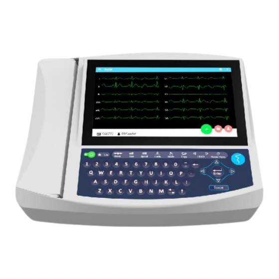
System Description 1. Top Panel Figure 2-1 Top Panel Display Screen: ECG waveforms, patient information, messages, etc are displayed on the screen (See 1-1 for details). Recorder: to load recording paper and record ECG waveforms. Control panel: to control the system operation (See 1-2 for details). -
Page 14: Display Screen
1.1 Display Screen Dena is equipped with a TFT color screen. All 12-lead ECG waveforms, HR value, Patient name/ID, Date and Time, system operating status, error and informative messages are displayed on the screen. Figure 2-2 Display Screen Header Area (inactive): The Header Area is at the top of the screen. - Page 15 Waveform/ Menu Area: 12-lead ECG waveforms are displayed on the screen and their arrangement can not be changed. ECG lead type is displayed in Waveform Area. Message Area: The message area is divided into two parts: 1- Lead error message area: All electrodes connection is checked regularly by the system and in case of improper connection, the related message will appear in this area in red (Figure 2-2- 2- Informative and system error messages area (Figure 2-2-...
-
Page 16: Control Panel
1.2 Control Panel Dena is designed in such a way that user can easily perform operations using some keys and touch screen. ① Menu Press to access Main Menu. ② Lead ▲ Press to select next lead(s). ③ Copy Press to record the last saved data ④... -
Page 17: Indicators
Figure 2-3 Control Panel Before using the electrocardiograph, check function of all keys and make sure that it is in proper working order. 1.3 Indicators The POWER switch (On/Off) is located on the control panel (Figure 2-3). There are three indicators for power, device and battery on the control panel. -
Page 18: Bottom Panel
2. Bottom Panel Figure 2-4 Bottom Panel Handhold: For transporting the device. Battery Compartment: For loading the battery. 3A fast fuse If the device is to be stored for a long period (more than 10 days), the fuse should be removed in order to prevent battery discharge. - Page 19 Power Supply: 100-240 VAC, 160 VA, 50/60 Hz The following connectors are located at the right side of the device: Connector of ECG cable Network connector Connector for PC connection USB port for data export and software update Figure 2-6 Side Panel...
-
Page 20: Built-In Battery
4. Built-in Battery The electrocardiograph is equipped with a rechargeable battery. The battery will charge automatically once you connect the system to the AC INPUT (whether the device is on or off). When the battery is fully discharged, it takes about 5 hours to charge it. The system can run on a fully-charged battery when the power cord is unplugged. - Page 21 The electrocardiograph will turn off automatically if the battery power is too low. When the electric power is going out, the message "BATTERY LOW" will be displayed. Use only the manufacturer recommended batteries. Other batteries may result in fire.
- Page 22 ECG Electrodes Connection ECG cable consists of two parts: main cable that is connected to the device and lead wires that are connected to the patient Use only one type of electrode on the same patient to avoid variations in electrical impedance. It is recommended to use silver/silver chloride electrode.
- Page 23 Connection of the Limb Electrodes 4 electrodes of 10 ECG electrodes are attached to the limbs. Reference lead is the electrode connected onto the right leg. Before connecting electrodes: 1- Prepare the patient’s skin. ■ The skin is a poor conductor of electricity, therefore preparation of the patient's skin is important to facilitate good electrode contact to skin.
- Page 24 Connection of the Chest Electrodes Before connecting electrodes: 1- Prepare the patient’s skin. ■ The skin is a poor conductor of electricity, therefore preparation of the patient's skin is important to facilitate good electrode contact to skin. ■ Shave hair from sites, if necessary. ■...
- Page 25 There are different labels and color codes for ECG electrodes according to IEC and AHA standards. Select ECG cable with regard to acceptable standard in your hospital. IEC Standard: Site for electrodes Symbol for electrodes Color code for electrodes Right arm Left arm Yellow Right leg...
- Page 26 Lead Placement Diagram Figure 2-9 Lead placement diagram...
-
Page 27: Section 3. Device Setting
Section 3. Device Setting For more information about different types of recording, please refer to section 6 (Recording Operation). Sync recording can be performed only in Automatic and Periodic modes. Navigation Drawer Click on the left side of the screen to access the below menu: Figure 3-1 Navigation Drawer The following items can be set through this menu: ... - Page 28 Rec State: Available options for this item are Real time and Sync. In the Sync mode, the signals of different leads are recorded simultaneously i.e. recording of all leads starts at the same time. Rec Mod: Available options for this item are 6 channels and 12 channels. ...
- Page 29 Drift Filter: Press to switch ON or OFF. This filter is used to reduce signal oscillations resulting from patient breathing and movement. -3dB cutoff frequency of this filter is about 0.6 Hz. Using this filter will remove the frequencies below the cutoff value from the ECG report. If the drift filter is switched off, the cutoff frequency of the device will be about 0.05Hz.
- Page 30 The EMG filter is an adaptive, non-linear and time- variant low pass filter that is applied to ECG signals. Since EMG is a non- linear filter, user should be trained by a qualified person to use this filter. In some cases, using the EMG filter may affect P, QRS and T waves. Lowpass and non-linear EMG filter may decrease amplitude of 10 Hz and higher frequency signals for different morphologies of ECG signal.
-
Page 31: Section 4. Recording Operation
“Rec Setting Menu” and “Rec Mode”. Signal recovery accuracy: With regard to maximum frequency bandwidth of 150 Hz and sampling rate of 1000 samples/s, the signal recovery accuracy of Dena Electrocardiograph complies with IEC 60601-2-25 standard requirements. General The Dena electrocardiograph is equipped with Saadat thermal recorder. -
Page 32: Recording Type
Recording Type Manual Recording Press Mode key on the screen or the control panel to toggle between Manual 6, and Manual 12. Press the Start/Stop key on the control panel to start recording. The recording will continue until you press this key again. Press Lead▲... -
Page 33: Recorder Paper
Recorder Paper Use only heat sensitive recording paper with 210 mm width. Use only the manufacturer recommended record paper, otherwise the recording quality may be poor and the thermosensitive printhead may be damaged Do not touch the recorder head while recording and immediately after recording because it is so hot and may lead to personal injury including burns. - Page 34 ■ Open the recorder door. ■ Place the paper roll in the compartment. ■ Close the recorder door firmly.
- Page 35 Do not open the recorder door during recording. This can damage it. The paper detector may not operate properly if covered with foreign matter. Therefore, if you find foreign matter on the sensor, remove it and clean the sensor. During the recorder operation the record paper exits steadily.
-
Page 36: Recorder Cleaning
Recorder Cleaning Accumulation of paper powder or foreign matter between the thermal head and platen roller reduces the print quality. Clean the head elements and platen roller surface using a cloth moistened with alcohol. Wait until the alcohol dries, then close the recorder door. Do not clean the recorder immediately after recording because thermal head and its surrounding area are hot during and after recording. -
Page 37: Section 5. Patient Safety
Section 5. Patient Safety The electrocardiograph system is designed to comply with the international safety standards requirements for medical electrical equipment. This device has floating input (isolated electricity) and is protected against the effects of defibrillation. If correct electrodes are used in accordance with the manufacturer instructions, the display screen will recover within 10 seconds after defibrillation. -
Page 38: Grounding The Electrocardiograph
Grounding the electrocardiograph To protect the patient and hospital personnel, the electrocardiograph system must be grounded. The device is equipped with a detachable 3-wire cable which grounds the instrument to the power line ground (protective earth) when plugged into an appropriate 3-wire receptacle. If a 3-wire receptacle is not available, consult the hospital electricians. -
Page 39: Section 6. Getting Started
Section 6. Getting Started 6-1 Open the package. Open the package and take out the electrocardiograph and accessories carefully. Keep the package for possible future transportation or storage. ■ Check the device for any mechanical damage. ■ Check existence of accessories and contents according the following checklist: Electrocardiograph device 1 unit 1 piece... - Page 40 Make sure that the battery indicator lights. If it does not light, check your local power supply and power cable connection. If the problem still exists, contact the After -Sales Services department. The battery needs to be charged after transportation or storage.
-
Page 41: Section 7. Technical Specifications
Section 7. Technical Specifications CLASSIFICATION Protection against electroshock Class I, Type CF , defibrillation-proof applied part Mode of operation Continues operation equipment Harmful Liquid Proof Degree Ordinary equipment, (without Liquid Proof) Method of sterilization and disinfection Refer to chapter 10 for detail. Not suitable for use in the presence of a flammable Safety of anesthetic mixture anaesthetic mixture with air or with oxygen or nitrous... - Page 42 Recorder Model SAADAT Thermal Printer Print Method Thermal dot line printing Dots per line 1726 dots 16 dots/mm (Horizontal) Resolution 8 dots/mm (Vertical) Printing Speed 6.25, 12.5, 25, 50 mm/s Paper Width 210mm Print Width 210mm 12 Lead ECG Waveforms, HR Value, system model,...
-
Page 43: Section 8. Care And Cleaning (Pm)
Section 8- Care and Cleaning 8-1 System Check Before using the device, ■ Check if there is any mechanical damage in the system and accessories. ■ Check if the power cable and accessories are firmly connected. ■ Check if all the keys function correctly and are in proper condition. If you find any damage in the electrocardiograph, stop using it on patient, and contact the biomedical engineer of the hospital or the manufacturer After Sales Service. - Page 44 8-2 Cleaning and Disinfection General Points Use only the substances approved by us and methods listed in this chapter to clean or disinfect your equipment. Manufacturer makes no claims regarding the efficacy of the listed chemicals or methods as a means for controlling infection.
- Page 45 External surfaces In-between patients and as required: For cleaning: wipe gently using a moist cloth and warm soapy water or mild detergent and for disinfection use the following recommended agents: ■ Alcohol 70% ■ Isopropyl alcohol ■ N-propanol Display screen In-between patients and as required use clean and soft cloth with neutral detergent and with Isopropyl alcohol may be used for cleaning and disinfection.
- Page 46 Also, trolley (if applicable) should be cleaned and disinfected after each patient or when necessary, using a soft, clean cloth soaked in mild soapy water and, if necessary, Isopropyl alcohol, and then wiped with a dry cloth. 1) To avoid damaging of the ECG cable, lead wires and electrodes do not immerse it in any liquid.
- Page 47 Single- Device parts Cleaning Disinfection Sterilization In-between patients In-between patients and To avoid extended and as required wipe as required use damage to the External surface of device gently using a moist ■ Alcohol 70% equipment, sterilization cloth and warm ■...
- Page 48 8-3 Preventive Maintenance (PM) To avoid damage to the equipment, disinfection should be performed according to the Hospital Maintenance Schedule. It is recommended that the system is calibrated by manufacturer every year, but it has to be calibrated once every 2 years. In addition, the system lifetime is 10 years.
- Page 49 The preventive maintenance (PM) checklist #PL-F-33 should be completed by responsible individuals of healthcare center. It should be noted that PM checklist only is used to perform systematic inspection of the equipment and will not guarantee their correct function. SAADAT Co. Form No. : PL-F-33 PM Form ( Electrocardiograph )
- Page 50 SAADAT Co. Form No. : PL-F-33 PM Form ( Electrocardiograph ) Name and signature of person in charge: Name and signature of expert:...
- Page 51 Section 9. Troubleshooting Repairing the internal parts of the electrocardiograph must be only done by trained and authorized personnel of After Sale Service; otherwise the manufacturer will not take any responsibility for any possible hazard to the patient and the device. Troubleshooting guide is intended to help users to solve minor problems caused by incorrect use of the electrocardiograph or failure of accessories.
-
Page 52: Section 9. Troubleshooting
Problem Possible Cause Solution ● Patient has stress or placed in an uncomfortable condition. ● Patient feels cold and starts High frequencies and muscle artifacts ● Relax the patient. shaking. make ECG signal noisy. ● Check electrodes connection. ● Improper placement of patient (This may occur concurrently with AC ●If the problem persists, use hands and feet. - Page 53 EKG Suction chest electrode, Adult , FIAB, Ref F9009SSC P28047 EKG Clamp electrodes, Pediatric, FIAB , Ref F9023SSC P28048 ECG Suction chest electrode, Pediatric-FIAB , Ref F9015SSC P28078 Electrocardiograph Cable,10wires, Banana Ends (SAADAT) P28045 ECG GEL P28114 Recorder Paper, 210mm , Roll...
-
Page 54: Appendix I- Accessories
APPENDIX II- List of the System Parameters (Selections and Defaults) ITEM SELECTION DEFAULT Task bar Menu Manual 12, Manual6, Auto 12, Recording Mode Auto 3 Auto 6 Sensitivity 2.5, 5, 10, 20 mm/mv Paper Speed 6.25, 12.5, 25, 50 mm/s Print Mode Print Modes Auto, Manual... - Page 55 APPENDIX III -Error Messages Message Cause Solution Remarks Leads Error Messages Lead RA is not Make sure that The message is CHECK RA properly connected to mentioned electrode is displayed in red color patient. properly connected. on the screen. Lead LA is not Make sure that The message is CHECK LA...
-
Page 56: Appendix Iii -Error Messages
Message Cause Solution Remarks Turn the system off and on. If the problem still The message blinks in The Print head voltage Head Hight Vol exists, contact the yellow color on the is high. manufacturer’s After screen. Sales Service. 1- Turn the system off and on. -
Page 57: Appendix Iv-Emc
APPENDIX IV-EMC Use only the recommended manufacturer accessory .Using the accessory other than in relevant chapter may cause to increase the EMISSION or decrease the IMMUNITY of system. Measurements can be affected by mobile and RF communications equipment. It should be assured that the Electrocardiograp is used in the electromagnetic environment specified To prevent EMC effect on the Electrocardiograp, the system should not be used adjacent to or stacked with other equipment and that if... - Page 58 Guidance and manufacturer's declaration – Dena 1210 emissions The Dena 1210 is intended for use in the electromagnetic environment specified below. The customer or the user of the Dena 1210, should assure that it is used in such an environment. Electromagnetic environment -...
- Page 59 NOTE . c . volt rior tion . l e Guidance and manufacturer's declaration – electromagnetic immunity The Dena 1210 is intended for use in the electromagnetic environment specified below. The usto Dena 1210 should nviron . nt Electromagnetic Immunity test...
- Page 60 3 V/m ENCLOSURE Radiated RF IEC 61000-4-3 80 MHz – 2,7 GHz 80 % AM at 1 kHz Proximity fields from RF wireless communications Refer to the ENCLOSURE equipment following table (table 9 of EN IEC 61000-4-3 60601-1-2: 2015) Test specifications for ENCLOSURE PORT IMMUNITY to RF wireless communications Test Maximum IMMUNITY TEST...
- Page 61 modul 1700- ation 1990 1900; DECT; 1970 LTE Band 1, 3, 4 25; UMTS Bluetooth, WLAN, 802.11 Pulse 2400- b/g/n, odul tion 2450 2570 217 Hz RFID 2450, LTE Band 7 5240 Pulse b) 5100- WLAN modulation 5500 217 Hz 5800 802.11 a/n 5785...
Need help?
Do you have a question about the Dena and is the answer not in the manual?
Questions and answers