Table of Contents
Advertisement
Quick Links
Advertisement
Table of Contents
Troubleshooting

Related Manuals for Saadat Dena


Summary of Contents for Saadat Dena
- Page 1 SAADAT Co. User Manual Dena Electrocardiograph Dena 650 (Linux) D00912-4.2...
- Page 2 POOYANDEGAN RAH SAADAT CO. No. 4, 1st East St., Ettehad Blvd., Damavand St., TEHRAN, IRAN Post box: 1658916599 Tel: +98 21 77960719, +98 21 77962181 Fax: +98 21 77964239 Customer Services: Tel: +98 21 73098000, +98 21 77798910 Fax: +98 21 77960761...
-
Page 3: Table Of Contents
Contents Manual Purpose .......................... I Symbols ............................. II General warnings ........................III Patient’s safety ........................VII Grounding ..........................VIII 1) Introduction ..........................1 General ...........................2 Features...........................2 Signal recovery accuracy ......................2 Environment ...........................2 Intended Use ...........................3 Getting started .........................3 Top Panel ..........................5 Display Screen ........................5 Header Area: ........................6 Waveform/ Menu Area: .......................6... - Page 4 ECG Electrodes Connection ....................32 Connection of the Limb Electrodes..................33 Connection of the Chest Electrodes ..................34 Lead Placement Diagram ...................... 36 Recorder paper ........................36 Paper loading ........................37 Information printed on the recorder paper ................39 Recorder Cleaning ......................... 40 5) Recording operation ......................
-
Page 6: Manual Purpose
Manual Purpose This manual provides the instructions necessary to operate Electrocardiograph device based on its intended use. Observance of this manual is a prerequisite for proper operation and ensures patient and operator safety. If you have any question about the device, please contact our customer service. Intended Audience This manual is provided for the clinical medical professionals. -
Page 7: Symbols
Symbols Symbol Definition Consult user manual of the device and pay attention to the warnings and cautions. The device is IEC60601-1 type CF (Defibrillation proof applied part) equipment. The units displaying this symbol provide an F-type isolated (floating) patient applied part with a high degree of protection against shock and is suitable to use with defibrillator simultaneously. -
Page 8: General Warnings
General warnings General warnings Please refer to this section for overall safety information. Warning Electrocardiograph system is intended to be used only by qualified medical staff. Warning Before use, carefully read this manual and directions for use of any accessories. Warning The electrocardiograph is intended for use only as an adjunct in patient assessment. - Page 9 General warnings Warning When defibrillator is used, the signals may be disturbed for a few seconds, after which the device will continue to operate normally. Warning Do not touch the patient, bed or devices nearby during defibrillation. Warning The operator must check that the system and accessories function safely and see that it is in proper working condition before being used (e.g.
- Page 10 General warnings Warning To prevent the environment pollution, the device and accessories (e.g. battery) shall be disposed in accordance with national laws after their useful lives. Contact your municipality to check where you can safely dispose of old batteries. Warning Do not expose the system near any local heating item such as the direct radiation.
- Page 11 General warnings Warning To protect patient against the electrical shock hazards, the electrocardiograph device needs to be connected to grounded power receptacle. Warning Electrocardiograph needs to be installed and put into service according to the EMC information provided in the Appendix 3. Warning To prevent EMC effect on the electrocardiograph, it should not be used adjacent to or stacked with other equipment and that if adjacent or stacked use is necessary, the system...
-
Page 12: Patient's Safety
Patient’s safety The electrocardiograph system is designed to comply with the international safety standards requirements for medical electrical equipment. This device has floating input (isolated electricity) and is protected against the effects of defibrillation. If correct electrodes are used in accordance with the manufacturer instructions, the display screen will recover within 10 seconds after defibrillation. -
Page 13: Grounding
Grounding To protect the patient and hospital personnel, the electrocardiograph system must be grounded. The device is equipped with a detachable 3-wire cable which grounds the instrument to the power line ground (protective earth) when plugged into an appropriate 3-wire receptacle. If a 3-wire receptacle is not available, consult the hospital electricians. -
Page 14: Introduction
Chapter 1: Introduction 1) Introduction... -
Page 15: General
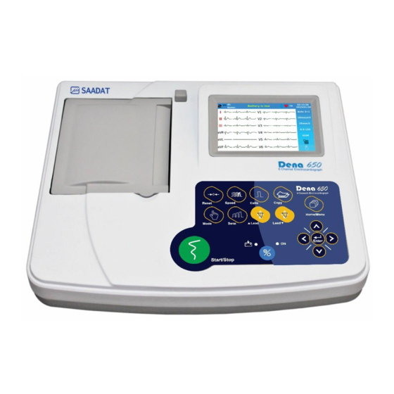
Chapter 1: Introduction General Dena is a small, light-weight and portable Electrocardiograph device. It is equipped with a color TFT touch screen, recorder and built-in battery. Features Dena is applicable to adult and neonatal patients and capable of: _ Displaying 12-lead ECG waveform... -
Page 16: Intended Use
Chapter 1: Introduction Intended Use Dena is an advanced electrocardiograph which is designed to record electrical signals of the heart in up to six channels (10-wire) using a thermal printer with adjustable filter, gain, speed, and mode. This device is applicable to adults and neonates in all parts of the medical center and used by healthcare professionals for diagnostic purposes. - Page 17 Chapter 1: Introduction Make sure that the battery indicator lights. If it does not light, check your local power supply and power cable connection. If the problem still exists, contact the After sales services department.. The battery needs to be charged after transportation or storage. If the power cable is not plugged in before turning on the device, the device may not work properly because of insufficient power.
-
Page 18: Top Panel
Control panel: to control the system operation (See 1-1 for details). Display Screen Dena is equipped with a TFT color screen. All 12-lead ECG waveform, HR value, Patient name/ID, Date and Time, system operating status, error and informative messages are displayed on the screen. -
Page 19: Header Area
Chapter 1: Introduction Figure 1-2 Display screen Header Area: The Header Area is at the top of the screen. The heart rate, patient name/ ID, current date and time and system operating status are displayed in this area. This information is displayed on the screen during the system operation. -
Page 20: Touch Screen Keys
Refer to Control Panel for details. Warning Do not touch the screen with sharp objects. Control Panel Dena is designed in such a way that user can easily perform operations using some keys and touch screen. Figure 1-3 Control Panel... - Page 21 Chapter 1: Introduction ① Menu Press to access Main Menu. ▼ ② Lead Press to select next lead(s). ③ Copy Press to record the last saved data ▲ ④ Press to select previous lead (s). Lead ⑤ Calib Press to record a 1mv calibration signal. ⑥...
-
Page 22: Indicators
Chapter 1: Introduction Warning Before using the electrocardiograph, check function of all keys and make sure that it is in proper working order. Indicators The POWER switch (On/Off) is located on the control panel (⑫ in the figure 1-3). There are two indicators for power and battery on the control panel. -
Page 23: Rear Panel
Chapter 1: Introduction Rear panel Figure 1-5 Rear panel AC Power input: 100-240 VAC, 60 VA, 50/60 Hz Side panel The following connectors are located at the right side of the device: Figure 1-6 Side panel Connector of ECG cable USB port for data export and software update Built-in Battery The electrocardiograph is equipped with a rechargeable battery. - Page 24 Chapter 1: Introduction The icon in the Header Area indicates the battery charge level. The table below illustrates the icon in different conditions. Icon Battery status The battery disconnection The battery is charging The device is plugged in 25% charged 25% charged,the device is plugged in 50% charged 50% charged, the device is plugged in...
- Page 25 Chapter 1: Introduction...
-
Page 26: General Settings
Chapter 2: General settings 2) General settings... -
Page 27: General
It is recommended that the device is set properly before recording. Main Menu Dena has a flexible configuration which can be changed through Main Menu. You can access the Main Menu by pressing Menu key on the control panel or touching Menu on the screen (Figure 3-1). -
Page 28: Print Mode Menu
Chapter 2: General settings Print Mode Menu Select Print Mode from the Main Menu to access the below menu: Figure 2-2 Print mode menu The following items can be set through this menu: Print Mode: Available options are Auto, Manual and Rhythm. Auto: Automatic modes of recording are 1+1, 3, 3+1 and 6. -
Page 29: Recorder Setting Menu
Chapter 2: General settings Header: Select ON to print the signal and recording information on header of the recorder paper. Select OFF to print only signal on the paper (without any information). Recorder Setting Menu Select Rec Setting from the Main Menu to access the below menu: Figure 2-3 Recorder setting menu The following items can be set through this menu: ... -
Page 30: Filters Menu
Chapter 2: General settings Filters Menu Select Filters from the Main Menu to access the below menu: Figure 2-4 Filter setting menu The following items can be set through this menu: Lowpass Filter: Press to toggle between 25, 35, 75, 150 Hz and Off. This filter is used to remove muscle artifacts and high frequency noises, yet some of the signal details might be removed. - Page 31 Chapter 2: General settings HUM Filter: Press to toggle between ON and OFF. Select this filter with regard to your local AC frequency. If the HUM filter is turned on, the third harmonic in accordance with the selected frequency will be deleted. In other words, when the HUM filter is detected to be 50 Hz, the frequency of 150Hz as well as 50 Hz will be removed.
- Page 32 Chapter 2: General settings 4.It is necessary to mention, if the LowPass filters are used, the amplitude of the QRS complex will be reduced. 5. If the EMG filter is enabled, the available LowPass filters will be Off, 75 Hz and 150 Hz. After setting On the EMG filter, wait a few seconds before recording.
-
Page 33: About Menu
Chapter 2: General settings About Menu Select this item from the Main Menu to view product and manufacturer information in the below menu. Figure 2-5 About menu User Setting Menu Select User from the Main Menu to access the below menu: Figure 2-6 User setting menu The following items can be set through this menu: ... -
Page 34: Setting Menu
Chapter 2: General settings Warning For patients with pacemaker, the PACE DETECT function must be switched "ON", otherwise, the pacing impulse may be counted as normal QRS complex. Warning In patients with pacemaker, if the PACE DETECT function is "OFF", turn off the low pass (25Hz, 35Hz) and EMG filters to check pacemaker function. - Page 35 Chapter 2: General settings The below parameters can be set through this menu: Date/Time: Press to open the below menu: - Calendar Type: Available options are Solar and Christian. - Date: To set the date. - Time: To set the time. Figure 2-8 Time setting menu Figure 2-9 Date setting menu...
- Page 36 Chapter 2: General settings Hospital/Ward: Select this item from the Setting Menu to open the virtual keyboard (figure 2-10) and enter hospital or ward name in the below window. Figure 2-10 Virtual keyboard (a) numbers and symbols, (b) characters ...
- Page 37 Chapter 2: General settings Default: To load factory default settings. Because of changing all your previous settings, the system will ask you to confirm this setting. Figure 2-12 Default factory Factory: Select this item to access the below window. Only manufacturer’s authorized personnel have access to this window.
- Page 38 Chapter 2: General settings Language: Available options are English and Persian. Figure 2-14 Language menu...
- Page 39 Chapter 2: General settings...
-
Page 40: Patient Information
Chapter 3: Patient information 3) Patient information... -
Page 41: Patient Data Entry
Chapter 3: Patient information This chapter will explain how to manage the patient information. Warning Enter the patient information correctly, otherwise it may be confused with the information of other patients. Touch Patient in the Main Menu, or select Patient using arrow keys and then press Enter, the Patient Information Menu will appear. - Page 42 Chapter 3: Patient information ID: Enter the patient ID number and press Save to exit from this window. Up to 20 characters can be entered in this field. Press Cancel to exit from this window and return to the previous menu. ...
- Page 43 Chapter 3: Patient information...
-
Page 44: Preparation
Chapter 4: Preparation 4) Preparation... -
Page 45: Patient Preparation
Chapter 4: Preparation Patient preparation Before you start recording the ECG, note the following: Give the patient enough time to relax after lying on the bed. Electrodes should be placed in suitable and prepared areas. The ambient temperature should be appropriate and the patient should not suffer from cold and tremors. -
Page 46: Connection Of The Limb Electrodes
Chapter 4: Preparation Warning When the device is used with electrocautery unit, please note the position of leads. In order to reduce the hazard of burns, the leads should be located away from the electrocautery pen and return electrode. Warning Use only one type of electrode on the same patient to avoid variations in electrical impedance. -
Page 47: Connection Of The Chest Electrodes
Chapter 4: Preparation Figure 4-1 Connection of the Limb electrodes Connection of the Chest Electrodes Before connecting electrodes: 1- Prepare the patient’s skin. The skin is a poor conductor of electricity; therefore preparation of the patient's skin is important to facilitate good electrode contact to skin. ... - Page 48 Chapter 4: Preparation Figure 4-2 Connection of the Chest electrodes There are different labels and color codes for ECG electrodes according to IEC and AHA standards. Select ECG cable with regard to acceptable standard in your hospital. IEC Standard: Site for electrodes Symbol for electrodes Color code for electrodes...
-
Page 49: Lead Placement Diagram
Chapter 4: Preparation Lead Placement Diagram Figure 4-3 Lead placement diagram Recorder paper Warning Use only heat sensitive recording paper with 110 mm width. Warning Use only the manufacturer recommended record paper, otherwise the recording quality may be poor and the thermosensitive print head may be damaged. -
Page 50: Paper Loading
Chapter 4: Preparation Warning Do not touch the recorder head while recording and immediately after recording because it is so hot and may lead to personal injury including burns. Paper loading ■ Press the recorder release button as shown in the figure below. ■... - Page 51 Chapter 4: Preparation ■ Close the recorder door firmly. Warning Do not open the recorder door during recording. This can damage it. The paper detector may not operate properly if covered with foreign matter. Therefore, if you find foreign matter on the sensor, remove it and clean the sensor. Warning During the recorder operation the record paper exits steadily.
-
Page 52: Information Printed On The Recorder Paper
Chapter 4: Preparation Warning If the paper is jammed, open the recorder door and remove the paper. Do not pull the paper out by force. Be careful when loading the paper in the recorder. Avoid damaging the thermosensitive print head. Do not touch thermosensitive print head. It is recommended to use the paper with colored marks intended to aware user that the paper is near to finish. -
Page 53: Recorder Cleaning
Chapter 4: Preparation If the Drift filter is disabled and the signals have offset, the signals may not be flush with the corresponding labels and the paper space may not be distributed properly. Recorder Cleaning Accumulation of paper powder or foreign matter between the thermal head and platen roller reduces the print quality. -
Page 54: Recording Operation
Chapter 5: Recording operation 5) Recording operation... -
Page 55: General
Please refer to chapter 2, “Rec Setting” and “Print Mode”, for details on recording settings. With regard to maximum frequency bandwidth of 150 Hz and sampling rate of 1000 samples/s, the signal recovery accuracy of Dena Electrocardiograph complies with IEC 60601-2-25 standard requirements. -
Page 56: Automatic Recording
Chapter 5: Recording operation ■ Manual 3+1 Select this mode and press Lead▲ and ▼Lead keys to choose between lead groups. Then press the Start/Stop key to start recording. In the recording paper, the first three waveforms are the waveforms of selected lead groups and the last one is the waveform of Rhythm lead. -
Page 57: Rhythm Recording
Chapter 5: Recording operation Only in Automatic and Periodic modes, stored data can be copied. Rhythm Recording Select Rhythm using the Mode key on the screen or control panel to see ECG waveform of the main lead in four traces. Press Start/Stop key to record according to “Length of Rhythm Rec” (Refer to chapter 2 “User Setting Menu”). - Page 58 Chapter 5: Recording operation It is possible to perform Manual and Automatic recording, when the Periodic mode is active. If the device is set on Manual modes and the Periodic mode in active, the device records the equivalent Automatic mode. For example, the device considers the Manual 3+1 as Auto 3+1. When the system is turned off and on, data cannot be copied.
- Page 59 Chapter 5: Recording operation...
-
Page 60: Ecg Analysis And Measurement
Chapter 6: ECG analysis and measurement 6) ECG analysis and measurement... -
Page 61: Reported Parameters In Global
In order to automatically analyze the ECG signal, the analysis and interpretation software of the University of Glasgow (The Glasgow Program) has been added to the Dena electrocardiograph. This software helps in more accurate diagnosis of the disease in two parts: Measurement and Interpretation. - Page 62 Chapter 6: ECG analysis and measurement Table 6-2 Reported parameters in Details ECG Parameters Description P Dur [ms] Time interval from the beginning to the end of the P wave QRS Dur [ms] Time interval from the beginning of the Q wave to the end of the S wave T Dur [ms] Time interval from the beginning to the end of the T wave ST Dur [ms]...
- Page 63 Chapter 6: ECG analysis and measurement Figure 6-2 Reported parameters in Details Each Interpretation phrase begins with a special letter that indicates the following: {H}: Indicates the title of report and is written in first line. {R}: Corresponds the rhythm interpretation. {D}: Indicates the details of the signal analysis and identifies the diagnostic terms.
-
Page 64: Data Management
Chapter 7: Data management 7) Data Management... -
Page 65: General
Chapter 7: Data management General All ECG recorded data in Auto and Rhythm modes will be automatically stored in the internal memory of the device for future reference. For this purpose, the Save option in User settings menu should be ON. Up to 100 records can be stored in the internal memory. - Page 66 Chapter 7: Data management Search: Enter patient name/ID in on-screen keyboard and press Search to view all stored data for the patient. Figure 7-2 Virtual keyboard (a) numbers and symbols, (b) characters If your intended name/ID is not available or entered incorrectly, the below message will appear. Figure 7-3 Message ...
-
Page 67: Export Menu
Chapter 7: Data management Figure 7-4 Review The following information are displayed in this window: ECG waveforms HR value Speed, Gain and recording mode Filter name Patient name and ID Date and time of recording Press Start/Stop key to print the stored ECG signals in the same condition as the recording time. Export Menu Select Export from the Main Menu to access the below menu. -
Page 68: Upgrade
Online data transfer to PC Dena electrocardiograph has the ability to transfer the information of the signals being drawn on the screen to a personal computer via the USB port of Device type. For this purpose, the request to install the said port must be notified to the manufacturer. - Page 69 Chapter 7: Data management Figure 7-6 ECG viewer software...
-
Page 70: Care And Cleaning
Chapter 8: Care and Cleaning 8) Care and Cleaning... -
Page 71: System Check
Chapter 8: Care and Cleaning System Check Before using the device, ■ Check if there is any mechanical damage in the system and accessories. ■ Check if the power cable and accessories are firmly connected. ■ Check if all the keys function correctly and are in proper condition. If you find any damage in the electrocardiograph, stop using it on patient, and contact the biomedical engineer of the hospital or the manufacturer After Sales Service. - Page 72 Chapter 8: Care and Cleaning 1- The electrocardiograph system and its belongings must be kept dust-free. 2- Do not use strong solvents such as acetone or ammonia. 3- Most cleaning agents must be diluted before use. 4- Don't use rough or sharp material or your fingernail to remove stubborn stains. 5- Do not let the cleaning agent enters into the chassis of the system.
-
Page 73: Disinfection
Take extra care when cleaning the screen because it is more sensitive to rough cleaning methods than the housing. Don't spray a liquid directly on the screen. Do not immerse any part of the Dena electrocardiograph in fluids. Disposable accessories shall not be sterilized or reused. ... - Page 74 Chapter 8: Care and Cleaning The following table summarizes the methods of cleaning, disinfecting and sterilizing different parts of the device: Single- Device parts Cleaning Disinfection Sterilization In-between patients In-between patients and avoid extended and as required wipe as required use damage ■...
-
Page 75: Maintenance
Chapter 8: Care and Cleaning Maintenance It is recommended to check the followings daily: Accessories function. Accessories physical health It is recommended to check the followings weekly: The cleanliness of the device. Physical health of device (frame, screen, keys, indicators, recorder button). ... -
Page 76: Preventive Maintenance (Pm) Checklist
The preventive maintenance (PM) checklist #PL-F-33 should be completed by responsible individuals of healthcare center. It should be noted that PM checklist only is used to perform systematic inspection of the equipment and will not guarantee their correct function. SAADAT Co. Form No. : PL-F-33 PM Form ( Electrocardiograph ) - Page 77 Chapter 8: Care and Cleaning...
-
Page 78: Troubleshooting And Error Messages
Chapter 9: Troubleshooting 9) Troubleshooting and Error messages... -
Page 79: Troubleshooting
Chapter 9: Troubleshooting Troubleshooting Repairing the internal parts of the electrocardiograph must be only done by trained and authorized personnel of After Sale Service; otherwise the manufacturer will not take any responsibility for any possible hazard to the patient and the device. Troubleshooting guide is intended to help users to solve minor problems caused by incorrect use of the electrocardiograph or failure of accessories. - Page 80 Chapter 9: Troubleshooting Problem Possible Cause Solution ● Patient has stress or placed uncomfortable condition. ● Relax the patient. ● Patient feels cold and starts High frequencies and muscle ● Check electrodes connection. artifacts make ECG signal noisy. shaking. ●If the problem persists, use ●...
-
Page 81: Error Messages
Chapter 9: Troubleshooting Error messages Message Cause Solution Remarks Leads Error Messages Make sure that The message is Lead R is not properly CHECK R mentioned electrode is displayed in red color connected to patient. properly connected. on the screen. Make sure that The message is Lead L is not properly... - Page 82 Chapter 9: Troubleshooting Message Cause Solution Remarks manufacturer’s After Sales Service. 1- Turn the system off and on. 2- Make sure that the 1- The print head battery is sufficiently The message blinks in voltage is low. Head Low Vol charged.
- Page 83 Chapter 9: Troubleshooting...
-
Page 84: Technical Specifications
Chapter 10: Technical specifications 10) Technical specifications... - Page 85 Indication : 0.5~2 ms, ±2~±250 mV Defibrillator Protection IEC 60601-2-25 Standards ECG Storage Internal Memory Up to 100 Records Recorder Model SAADAT Thermal Printer Thermal dot line printing Print Method Dots per line 832 dots 16 dots/mm (Horizontal) Resolution 8 dots/mm (Vertical)
- Page 86 Chapter 10: Technical specifications Printing Speed 6.25, 12.5, 25, 50 mm/s Paper Width 110 mm Print Width 104 mm 12 Lead ECG Waveforms, HR Value, Patient Information, Printed data Hospital/ ward, system model, software version, date and time, paper speed, sensitivity, filter Auto, Manual, Periodic Recording Mode Auto 1+1, Auto 3, Auto 3+1, Auto 6, Manual 1+1, Manual 3,...
- Page 87 Chapter 10: Technical specifications...
-
Page 88: Appendix 1: Accessories
Appendix 1: Accessories Appendix 1: Accessories... - Page 89 EKG Suction chest electrode, Adult , FIAB, Ref F9009SSC EKG Clamp electrodes, Pediatric, FIAB , Ref F9023SSC P28047 ECG Suction chest electrode, Pediatric-FIAB , Ref F9015SSC P28048 Electrocardiograph Cable,10wires, Banana Ends (SAADAT) P28078 ECG GEL P28045 Recorder Paper, 110mm , Roll P28026 Warning Use only the manufacturer recommended ECG cable.
-
Page 90: Appendix 2: System Parameters
Appendix 2: System parameters Appendix 2: System parameters... - Page 91 Appendix 2: System parameters ITEM SELECTION DEFAULT Task bar Menu Manual 1+1, Manual 3, Auto 3 Recording Mode Manual 3+1, Manual6, Auto 1+1, Auto 3, Auto 3+1, Auto 6, Rhythm Sensitivity 2.5, 5, 10, 20 mm/mv Paper Speed 6.25, 12.5, 25, 50 mm/s Patient Information Menu Name Blank...
- Page 92 Appendix 2: System parameters ITEM SELECTION DEFAULT Rhythm Length of Rhythm 30, 60, 90, 120, 150, 180 Seconds Recording Header ON/ OFF I, II, III, aVL, aVF, aVR, Rhythm Lead V1, V2, V3, V4, V5, V6 Recorder Setting Menu 3-12 Seconds, Rec Time Interval=1(s) Off, 5-60 Min,...
- Page 93 Date & Time Calendar Type (Christian, Solar) Date Year, Month, Day, Cursor up, Cursor down Hour, Minute, Second Time Cursor up, Cursor down Factory Demo ON/ OFF SAADAT, SAADAT [M], DAHIAN Company Name SAADAT , TRIONARA Touch Sound Key Sound ON/ OFF...
-
Page 94: Appendix 3: Electro-Magnetic Compliance (Emc)
Appendix 3: Electro-magnetic compliance Appendix 3: Electro-magnetic compliance (EMC) - Page 95 Appendix 3: Electro-magnetic compliance Warning Use only the recommended manufacturer accessory .Using the accessory other than in relevant chapter may cause to increase the EMISSION or decrease the IMMUNITY of system. Warning Measurements can be affected by mobile and RF communications equipment. It should be assured that the Electrocardiograph is used in the electromagnetic environment specified.
- Page 96 Guidance and manufacturer's declaration – electromagnetic emissions The Dena Electrocardiograph is intended for use in the electromagnetic environment specified below. The customer or the user of the Dena should assure that it is used in such an environment. Emissions test...
- Page 97 Guidance and manufacturer's declaration – electromagnetic immunity The Dena Electrocardiograph is intended for use in the electromagnetic environment specified below. The customer or the user of the Dena should assure that it is used in such an environment. IEC 60601...
- Page 98 If the measured field strength in the location in which theDenais used exceeds the applicable RF compliance level above, the Dena should be observed to verify normal operation. If abnormal performance is observed, additional measures may necessary, such as reorienting or relocating the Electrocardiograph.
- Page 99 The Dena Electrocardiograph is intended for use in the electromagnetic environment in which radiated RF disturbances are controlled. The customer or the user of the Dena can help prevent electromagnetic interference by maintaining a minimum distance between portable and mobile RF communications equipment (transmitters) and the Dena as recommended below, according to the maximum output power of the communications equipment.
-
Page 100: Appendix 4: The Glasgow Program
Appendix 4: The GLASGOW program Appendix 4: The GLASGOW program... - Page 101 Appendix 4: The GLASGOW program LIST OF ABNORMALITIES ATRIAL ABNORMALITIES Possible right atrial abnormality Consider left atrial abnormality Possible right atrial abnormality consistent with pulmonary disease Possible left atrial abnormality Possible biatrial enlargement QRS AXIS DEVIATION ...
- Page 102 Appendix 4: The GLASGOW program WPW pattern – probable left posteroseptal accessory pathway WPW pattern – probable left posterolateral accessory pathway HYPERTROPHY LEFT VENTRICULAR HYPERTROPHY Left ventricular hypertrophy Possible left ventricular hypertrophy Left ventricular hypertrophy, possible digitalis effect ...
- Page 103 Appendix 4: The GLASGOW program ANTEROSEPTAL MYOCARDIAL INFARCTION STATEMENTS *** ANTEROSEPTAL INFARCT – POSSIBLY ACUTE *** Anteroseptal infarct – age undetermined Possible anteroseptal infarct – age undetermined Cannot rule out anteroseptal infarct – age undetermined Abnormal Q waves of undetermined cause ...
- Page 104 Appendix 4: The GLASGOW program POSTERIOR MYOCARDIAL INFARCTION Possible posterior infarct – age undetermined Possible posterior extension of infarct Tall R V1/V2 probably reflect the infarct ANTEROLATERAL MYOCARDIAL INFARCTION *** ANTEROLATERAL INFARCT – POSSIBLY ACUTE *** ...
- Page 105 Appendix 4: The GLASGOW program CRITICAL VALUES Consider Acute STEMI Acute MI/Ischemia Extreme Tachycardia Extreme Bradycardia Significant Arrhythmia Prolonged QTc Interval INTERVALS Short PR interval Prolonged QT interval Short QT interval DOMINANT RHYTHM STATEMENTS ...
- Page 106 Appendix 4: The GLASGOW program SUPPLEMENTARY RHYTHM STATEMENTS with PVC(s) with frequent PVCs with multifocal PVCs with frequent multifocal PVCs with interpolated PVC(s) with multifocal interpolated PVCs with paroxysmal idioventricular rhythm with multifocal PVCs ...
Need help?
Do you have a question about the Dena and is the answer not in the manual?
Questions and answers