Advertisement
Quick Links
Advertisement

Related Manuals for Saadat Dena 350


Summary of Contents for Saadat Dena 350
- Page 1 SAADAT Co. Service Manual Electrocardiograph Dena 350 D00720-V4...
- Page 2 POOYANDEGAN RAH SAADAT CO. No. 4, 1st East St., Ettehad Blvd., Damavand St., TEHRAN, Address: IRAN Post box: 1658916599 Tel: +98 21 77960719, +98 21 77962181 Fax:+98 21 77964239 Customer Services: Tel: +98 21 73098000, +98 21 77798910 Fax: +98 21 77960761...
-
Page 3: Table Of Contents
Service Manual – Dena 350 Contents Contents Chapter 1. Introduction Chapter 2. Theory of operation Chapter 3. Technical specification of system Chapter 4. Installation Chapter 5. Programming Instruction Chapter 6. Test,Calibration and Upgrade procedures... -
Page 4: Chapter 1. Introduction
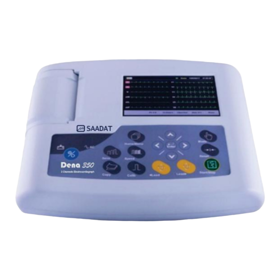
This service manual contains technical information about system for qualified service personnel to troubleshoot, maintain and repair the Electrocardiograph Dena 350. This Electrocardiograph Dena 350 is produced in POOYANDEGAN RAH SAADAT Co. So when you want to service these systems, you should refer to this manual but if you want to know about system settings and get more information about using them, you should refertothe operator’s manual. - Page 5 10kΩ, 3W at least) and do not use other cables 1.3 General information Dena 350 is a small, light-weight and portable Electrocardiograph usable in all areas due to portability and battery function capability. It has a 5 inch TFT color LCD with touch screen and built-in recorder.
- Page 6 Service Manual – Dena 350 Chapter 1. Introduction ▪ LCD Screen Electrocardiograph has a color TFT LCD screen. 12-lead ECG waveform, Heart Rate value, Patient ID, Date and Time, system operating status and error messages are displayed on the screen.
- Page 7 Service Manual – Dena 350 Chapter 1. Introduction ▪ Control Panel and Keys Electrocardiograph is designed so that the operator is able to control it through some keys and a touch LCD screen. 1-On/Off : Press to turn on or off the device.
- Page 8 Service Manual – Dena 350 Chapter 1. Introduction Figure 1-3 Electrocardiograph Control Panel and Keys ▪ Indicators There are two indicators for power and battery on the top panel. The green indicator lights up, when the device is plugged in (17in Figure 1-3). Depending on remaining charge of battery, battery indicator can be green, orange or red when the battery is fully-charged, half-charged or almost empty, respectively.
- Page 9 Service Manual – Dena 350 Chapter 1. Introduction 1.3.2 Bottom Panel Bottom view of device is shown in Figure 1-4. 1- Speaker outlet 2- Battery container Figure 1-4 Bottom Panel 1.3.3 Rear Panel There are the following sockets on the rear panel of the main unit (Figure 1-5).
- Page 10 Service Manual – Dena 350 Chapter 1. Introduction Figure 1-6 Right Side Panel 1.3.5 Left Panel The following parts are on the left side of the main unit: 1- Recorder release button 2- Connector of ECG cable Figure 1-7 Left Side Panel...
- Page 11 Service Manual – Dena 350 Chapter 1. Introduction 1.4 Explanations of the symbols in the Manual and device Symbol Definition Serial number Manufacture date Manufacturer information Consult user manual of the DENA system and pay attention to the warnings and cautions.
- Page 12 Service Manual – Dena 350 Chapter 1. Introduction 1.5 Factory Setting Menu Press Main/menu and enter to Main/menu window. Select the Factory Settings Menu from System Settings Menu and enter it by the means of entering factory code. FACTORY CODE Now you can: - Calibrate Touch.
-
Page 13: Chapter 2.Theory Of Operation
2.1.3 LCD and Touch Screen Display screen used in Dena 350 is a 5 inch TFT LCD with resolution of 800 × 480 pixels. On this LCD, a resistive touch screen is mounted which is one of the system inputs. This part is... - Page 14 Service Manual – Dena 350 Chapter 3. Technical specifications of system 2.1.4 Power board The power board performs AC/DC conversion in order to charge battery andsupply system power. This board has medical label and its input and output are isolated above 4000Vac. This board starts its functionality when connected to power line and continue its function as long as remains connected to power line.
-
Page 15: Chapter 3. Technical Specification Of System
In front panel, LCD, recorder mechanism, analog board andmotherboard are assembled. Also, membrane is mounted on the front panel. Figure 3-1 shows block diagram of device and figure 3-2 shows system diagram of Dena 350. Charger board Power board... - Page 16 Service Manual – Dena 350 Chapter 3. Technical specifications of system Battery USB Device SD Card Power Board Charger board Power Serial Data Analog Touch board Screen Motherboard Parallel Data Display Screen Membrane and LED Indicators Recorder mechanism Figure 3-2 Dena 350 System Diagram...
- Page 17 Service Manual – Dena 350 Chapter 3. Technical specifications of system 3.2 Circuit diagrams & part lists Last revision of circuit diagrams & part lists are available on master document in POOYANDEGAN RAH SAADAT Co. For more information, please contact with following email:...
-
Page 18: Chapter 4. Installation
7. Test the system according to test III procedure and fill out test forms. 8. Fill out the warranty card. 4.2 Trolley installation Open the trolley package and tight the separated parts together. Use only trolley approved by POOYANDEGAN RAH SAADAT Turn off system and unplug it before any installing operation. -
Page 19: Chapter 5. Programming Instruction
Service Manual – Dena 350 Chapter 5. Programming Instruction Chapter 5. Programming Instruction For programming Dena 350 Analog board and motherboard, “ST-Link” programmer is used. For more info, please refer to “ST-Link” programmer section in programming instruction (code: PP-W-05) -
Page 20: Chapter 6. Test,Calibration And Upgrade Procedures
Service Manual – Dena 350 Chapter 6. Test, Calibration and Upgrade Chapter 6. Test, Calibration and Upgrade procedures 6.1 Equipment ECG Simulator 6.2 Performance Test 6.2.1 Power On Test 1- Plug power cord on and press On/Off key so the device turns on. After one second, system will boot and its logo will appear. - Page 21 Service Manual – Dena 350 Chapter 6. Test, Calibration and Upgrade 6.3 Calibration System calibration should be performed every year or as frequent as dictated by hospital policy. If calibration is needed, please contact After Sales Service. 6.3.1 Calibration procedures On completion of each test and/or inspection, Test personnel should record the result of each test and whether it meets specified requirements, the final device will be confirmed.
Need help?
Do you have a question about the Dena 350 and is the answer not in the manual?
Questions and answers