Table of Contents
Advertisement
Quick Links
Advertisement
Table of Contents
Troubleshooting

Related Manuals for Saadat DENA 650


Summary of Contents for Saadat DENA 650
- Page 1 AADAT Co. User Manual Dena Electrocardiograph DENA 650 (Linux) D00912-7...
- Page 2 POOYANDEGAN RAH SAADAT CO. Address: No. 4, 1st East St., Ettehad Blvd., Damavand St., TEHRAN, IRAN Post box: 1658916599 Tel: +98 21 77960719, +98 21 77962181 Fax: +98 21 77964239 Customer Services: Tel: +98 21 73098000, +98 21 77798910 Fax: +98 21 77960761...
-
Page 4: Table Of Contents
Contents Manual Purpose ............................. I Symbols ..............................II Patient’s safety ........................... III Introduction ........................... 1 Device description ..........................2 Intended use ............................2 Features ............................... 2 Get started ............................3 Top panel ............................4 Bottom panel ............................. 11 Rear panel ............................13 Side panel ............................ - Page 5 General information .......................... 48 Archive Menu ........................... 48 Export Menu ............................. 51 Online data transfer to PC ......................... 52 Care and Cleaning ........................53 System check ............................ 54 Maintenance ............................55 Cleaning & Disinfection ........................56 Preventive Maintenance (PM) checklist ................... 59 Troubleshooting and Error messages ..................
-
Page 6: Manual Purpose
Manual Purpose Observance of this manual is a prerequisite for proper operation and ensures patient and operator safety. If you have any question about the device, please contact our customer service. Intended Audience This manual is provided for the clinical medical professionals. Clinical medical professionals are expected to have working knowledge of medical terminology and procedures as required for the device operation. -
Page 7: Symbols
Symbols Symbol Definition Consult user manual of the device and pay attention to the warnings and cautions. The device is IEC60601-1 type CF (Defibrillation proof applied part) equipment. The units displaying this symbol provide an F- type isolated (floating) patient applied part with a high degree of protection against shock and is suitable to use with defibrillator simultaneously. -
Page 8: Patient's Safety
Before use, carefully read this manual and directions for use of any accessories. DENA 650 is intended for use only as an adjunct in patient assessment. It must be used in conjunction with clinical signs and symptoms. ... - Page 9 Appendix 3. To prevent EMC effect on DENA 650, it should not be used adjacent to or stacked with other equipment and that if adjacent or stacked use is necessary, the system should be checked for normal operation in the configuration in which it will be used.
- Page 10 DENA 650 software is designed to minimize the risk of software errors. Due to the frequency band up to 150 Hz and the sampling rate of 1000 sample/s, the accuracy of signal reconstruction in DENA 650 is in accordance with the requirements of IEC 60601-2- 25 standard.
-
Page 12: Introduction
Chapter 1: Introduction 1) Introduction... -
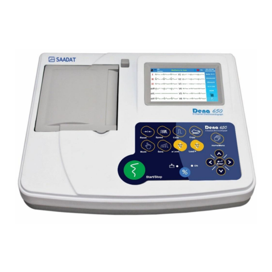
Page 13: Device Description
Intended use DENA 650 can be used for adults, children and infants. This device is intended for trained medical staff in all medical centers that have complied with the requirements of the medical location, for diagnostic purposes. -
Page 14: Get Started
WARNING If any sign or error message is observed in DENA 650 that may be due to its failure, please do not use it on the patient. In the following, the different parts of this device will be explained. -
Page 15: Top Panel
Control panel: to control the system operation. (more information follows). Display screen DENA 650 has a TFT color screen. The 12-wave ECG waveform, HR numerical value, patient name and ID, date and time, device status and system messages are displayed on this screen. The screen can be divided... - Page 16 ECG lead type is displayed in Waveform Area. DENA 650 constantly checks the connection of the electrodes and, if it detects that the electrodes are not properly connected, displays a red message in the waveform area (such as lead II in Figure 1-2-...
- Page 17 Chapter 1: Introduction Control panel DENA 650 is designed in such a way that user can easily perform operations using some keys and touch screen. Figure 1-3 illustrates these keys and indicators. Figure 1-3 Control panel...
- Page 18 Press to enter software menus or select menus options ⑮ Enter WARNING Before using the DENA 650, check function of all keys and make sure that it is in proper working order. Do not use sharp objects to touch the screen.
- Page 19 Chapter 1: Introduction Recorder WARNING Use only the manufacturer recommended record paper, otherwise the recording quality may be poor and the thermal head may be damaged. The thermal head and its surroundings are very hot during and immediately after recording, and touching it can cause injuries such as burns.
- Page 20 Chapter 1: Introduction 3- Place the paper roll inclined in the recorder and push it. 4- Place the other side of the paper roll in the recorder. Open the paper roll to leave some of it out of the recorder. 5- Close the recorder door firmly.
- Page 21 Chapter 1: Introduction WARNING Do not open the recorder door during recording. This can damage it. During the recorder operation the record paper exits steadily. Pulling the paper will damage the recorder. If the paper is jammed, open the recorder door and remove the paper. Do not pull the paper out by force.
-
Page 22: Bottom Panel
If the battery discharges in less than 1 hour, contact after-sales service to replace it. DENA 650 will turn off automatically if the battery power is too low. When the electric power is going out, the message "BATTERY LOW" will be displayed ... - Page 23 Chapter 1: Introduction Table 1-2 Battery status icons Battery stats Icon Battety disconnection Charging (below 20%) Pluged in and fully charged 20-40% charged 40-60% charged 60-80% charged 80-99% charged 20-40% charged, charging 40-60% charged, charging 60-80% charged, charging 80-99% charged, charging نکته...
-
Page 24: Rear Panel
Chapter 1: Introduction Rear panel figure 1-5 shows the rear panel. AC power input Figure 1-5 Rear panel Side panel The following connectors are located at the right side of the device: Figure 1-6 Side panel ECG cable connector USB port for data export and software update... - Page 25 Chapter 1: Introduction...
-
Page 26: System Settings
Chapter 2: System settings 2) System settings... -
Page 27: General
It is recommended that the device is set properly before recording. Figure 2-1 Main menu DENA 650 has a flexible configuration that can be changed through Main Menu. You can access the Main Menu by pressing Menu key on the control panel or touching Menu... -
Page 28: Print Mode Menu
Chapter 2: System settings Print Mode Menu Select Print Mode from the Main Menu to access the below menu: The following items can be set through this menu: Figure 2-2 Print mode menu available options are Auto, Manual and Rhythm. Print Mode: Auto: Automatic modes of recording are 1+1, 3, 3+1 and 6. -
Page 29: Recorder Setting Menu
Chapter 2: System settings Recorder Setting Menu Select Rec Setting from the Main Menu to access the below menu: Figure 2-3 Recorder setting menu The following items can be set through this menu: Rec Time: To set recording duration for different leads in Auto mode. It ranges from 3 to 12 seconds. -
Page 30: Filters Menu
Chapter 2: System settings Filters Menu Select Filters from the Main Menu to access the below menu: Figure 2-4 Filter setting menu The following items can be set through this menu: LowPass Filter: available options are Off and 25, 35, 75, 150 Hz. This filter is used to remove muscle noise and high frequency noise. - Page 31 Chapter 2: System settings WARNING The use of 25, 35, and 75 Hz LowPass filters may reduce the amplitude of the cardiac signal and omit some useful signal details. If you turn on the HUM filter, in proportion to the selected frequency, its third harmonic will also be removed.
- Page 32 Chapter 2: System settings In addition to the above filters, some filters with default settings (F1, F2, F3 and F4) are available in the system. These settings are shown in the below table that only F4 filter settings could be changed by user. Table 2-1 Default filters Filter LowPass...
-
Page 33: User Setting Menu
Save: Enable this item to save patient data and signals in Auto and Rhythm modes. Pace Detect: Available options are Off and On. DENA 650 detects and rejects pacemaker-generated signals from ECG signal, so that they will be ignored in determining heart rate. If you select On for patients with pacemaker, detected pacemaker signals will be marked on the ECG waveform as a white vertical line. -
Page 34: Setting Menu
Chapter 2: System settings Setting Menu Select Setting from the Main Menu to access the below menu: Figure 2-6 Setting menu The below parameters can be set through this menu: Date/Time: Press to open menus shown in figure 2-7 and 2-8. The following parameters can be set in these menus: Available options are Solar and Christian. - Page 35 Chapter 2: System settings Figure 2-8 Time setting menu Hospital/Ward: Select this item from the Setting Menu to open the virtual keyboard (figure 2-9) and enter hospital or ward name in the below window. Figure 2-9 Virtual keyboard (a) numbers and symbols, (b) characters Rec Test: Used to test the recorder function.
- Page 36 Chapter 2: System settings Figure 2-10 Recorder test Default: To load factory default settings. Because of changing all your previous settings, the system will ask you to confirm this setting. Figure 2-11 Default factory Factory: Pressing this key opens the virtual keyboard window (Figure 2-9). Screen calibration settings, hardware settings and Demo mode activation will be done in this menu.
-
Page 37: About
Chapter 2: System settings Touch Sound: To switch ON/OFF the sound of touch or hard keys. Figure 2-12 Touch sound menu Available options are English and فارس ی Language: By selecting any language, all the device menus and entries on the screen change to the same language Figure 2-13 Language menu About Select this item from the Main Menu to view product and manufacturer information in the below... -
Page 38: Patient Information
Chapter 3: Patient information 3) Patient information... -
Page 39: Patient Data Entry
Chapter 3: Patient information Patient Data Entry Select Patient from the Main Menu to access the below menu: Figure 3-1 Patient information menu To enter the patient information, select the Patient option. With each selection, a window corresponding to the desired option will open. ... - Page 40 Chapter 3: Patient information Blood Type: By default, the blood type is set to Unknown. Other options are A+, A-, B+, B-, AB+, AB-, O+ and O-. WARNING Enter patient information correctly. Otherwise, the stored information may be mistaken for other patients' information.
- Page 41 Chapter 3: Patient information...
-
Page 42: Patient Preparation
Chapter 4: Patient preparation 4) Patient preparation... -
Page 43: Actions Before Recording
Chapter 4: Patient preparation Actions Before Recording Before recording the signal, pay attention to the following: Give the patient enough time to relax after lying on the bed. If necessary, shave the hair where the electrodes are placed on the patient's skin. ... - Page 44 Chapter 4: Patient preparation WARNING Use only one type of electrode on the same patient to avoid variations in electrical impedance. It is recommended to use silver/silver chloride electrode. When dissimilar metals are used for different electrodes, the electrodes may cause large offset potentials due to polarization, which may be severe enough to prevent obtaining an ECG trace.
-
Page 45: Detection Of Electrode Disconnection
Figure 4-3 Connection of the Chest Electrodes Detection of electrode disconnection DENA 650 continuously monitors the connection status of the electrodes, and in the event of a disconnection, displays the relevant messages at the location of the signals on the screen (Figure 1-2). -
Page 46: Color Codes And Labels Of Electrodes
Chapter 4: Patient preparation Color codes and Labels of Electrodes There are different labels and color codes for ECG electrodes according to IEC and AHA standards. Select ECG cable with regard to acceptable standard in your hospital. IEC standard: Site for electrodes Symbol for electrodes Color code for electrodes... -
Page 47: Lead Placement Diagram
Chapter 4: Patient preparation Lead Placement Diagram Figure 4-4 Lead placement digram... -
Page 48: Recording Operation
Chapter 5: Recording Operation 5) Recording Operation... -
Page 49: Recording Types
Chapter 5: Recording Operation NTOE See the System settings chapter to view the recording settings. Recording Types Manual Recording Press Mode key on the screen or the control panel to toggle between Manual 1+1, Manual 3, Manual 3+1 and Manual 6. Press the Start/Stop key on the control panel to start recording. - Page 50 Chapter 5: Recording Operation Rhythm Recording Select Rhythm using the Mode key on the screen or control panel to see the ECG waveform of the Rhythm lead in four traces. Press Start/Stop key to record according to “Length of Rhythm Rec”. In this mode, there are always six channels of recording on the paper.
-
Page 51: Periodic Recording
Chapter 5: Recording Operation Periodic Recording To perform periodic recording: 1- Enter the “Recorder setting menu”, and select the desired time interval (5-60 min) for “Periodic Recording”. 2- Select number of recording repetitions. Available options are “infinite” and 1-20. 3- The recording type in this case is similar to other types of recording and is determined using the Print Mode menu. -
Page 52: Ecg Analysis And Measurement
Chapter 6: ECG analysis and measurement 6) ECG analysis and measurement... -
Page 53: General Information
In order to automatically analyze the ECG signal, the analysis and interpretation software of the University of Glasgow (The Glasgow Program) has been added to DENA 650. This software helps in more accurate diagnosis of the disease in two parts: Measurement and Interpretation. The Measurement section measures and reports the important parameters of the ECG signal and the Interpretation section uses the results of the Measurement section to diagnose the disease. - Page 54 Chapter 6: ECG analysis and measurement Heart Axis The cardiac vector (Heart axis) is the average sum of the electrical forces inside the heart, or in other words, the angle of the result of the vector of the heart's electrical activity. The electric vector can be calculated for P, QRS and T waves.
-
Page 55: Reported Parameters In Details Mode
Chapter 6: ECG analysis and measurement Reported parameters in Details mode In this mode, the details of 12 leads are reported in addition to the Global mode. These details are given in table 6-2. Table 6-2 Reported parameters in Details ECG parameters Description P Dur [ms]... - Page 56 Chapter 6: ECG analysis and measurement Measurement Interpretation Figure 6-4 Reported parameters in Global Interpretation Measurement Figure 6-5 Reported parameters in Details Each Interpretation phrase begins with a special letter that indicates the following: {H}: Indicates the title of report and is written in first line. {R}: Corresponds the rhythm interpretation.
- Page 57 Chapter 6: ECG analysis and measurement NOTE The measurement table is printed at the end of recording, only in Automatic and Sync recording. The units for time parameters and amplitude parameters, are millisecond [ms] and microvolt [µV], respectively. ...
-
Page 58: Data Management
Chapter 7: Data management 7) Data management... -
Page 59: General Information
All ECG recorded data in Auto and Rhythm modes, as weel as Periodic recordings, will be stored in the internal memory of DENA 650 for future reference. For this purpose, the Save option in User settings menu should be Enable. In case of disabling the Save option no data is saved in the Archive. - Page 60 Chapter 7: Data management Press to move to the previous or next record Swipe up and down to access the previous and next pages. Search: Enter patient name/ID in on-screen keyboard (figure 7-2) and press Search to view all stored data for the patient.
- Page 61 Chapter 7: Data management Figure 7-4 Review window The following information are displayed in this window: ECG waveforms HR value Speed, Gain and recording mode Filter name Patient name and ID Date and time of recording NOTE ...
-
Page 62: Export Menu
Chapter 7: Data management Export Menu Select Export from the Main Menu to access the below menu. Figure 7-5 Export menu Connect flash memory to the system and select Start to export all saved records in the system. When progress bar reaches 100%, data is exported completely. By selecting Start while the flash memory is not connected to the system, the message “Mass Storage Not Exists”... -
Page 63: Online Data Transfer To Pc
Online data transfer to PC DENA 650 has the ability to transfer the information of the signals being drawn on the screen to a personal computer via a Device USB port. For this purpose, the request to install the said port must be notified to the manufacturer. -
Page 64: Care And Cleaning
Chapter 8: Care and Cleaning 8) Care and Cleaning... -
Page 65: System Check
NOTE To ensure maximum battery life, let the DENA 650 runs on the battery, at least once a month, until it turns itself off and then recharge the battery. If you find any damage in DENA 650, stop using it on patient, and contact the biomedical engineer of the hospital or the manufacturer After Sales Service. -
Page 66: Maintenance
Chapter 8: Care and Cleaning Maintenance NOTE It is recommended that the device be calibrated once a year by the manufacturer, but calibration is mandatory every 2 years. The life of the device is 10 years. The hospital can also request a calibration whenever the accuracy of the device is in doubt. It is recommended that the following be checked daily: ... -
Page 67: Cleaning & Disinfection
Allow the device to dry completely before making connections. Make sure all connections are secure before using the system. NOTE 1- DENA 650 and accessories should be kept away from dust. 2- Do not use detergents that contain ammonia or acetone. 3- Most cleaning agents must be diluted before use. - Page 68 Chapter 8: Care and Cleaning External surfaces of the device In-between patients and as required, wipe gently using a moist cloth and warm soapy water or mild detergent to clean the device and also recommended to use 70% alcohol or Isopropyl alcohol or N- propanol for its disinfection Display screen In-between patients and as required use clean and soft cloth with screen cleaner or mild soapy...
- Page 69 Chapter 8: Care and Cleaning The following table summarizes the methods of cleaning, disinfecting and sterilizing the various parts of the device: Single- Device parts Cleaning Disinfection Sterilization In-between patients and avoid extended In-between patients and as required use damage as required wipe gently ■...
-
Page 70: Preventive Maintenance (Pm) Checklist
It should be noted that PM checklist only is used to perform systematic inspection of the equipment and will not guarantee their correct function. Pooyandegan Rah Saadat Co. Form No. : PL-F-33-V1 PM Form (DENA 650 Electrocardiograph ) State: City: Healthcare center:... - Page 71 Chapter 8: Care and Cleaning...
-
Page 72: Troubleshooting And Error Messages
Chapter 9: Troubleshooting and Error messages 9) Troubleshooting and Error messages... -
Page 73: Troubleshooting
Chapter 9: Troubleshooting and Error messages Troubleshooting Repairing the internal parts of DENA 650 must be only done by trained and authorized personnel of After Sale Service; otherwise the manufacturer will not take any responsibility for any possible hazard to the patient and the device. - Page 74 Chapter 9: Troubleshooting and Error messages ●Use the same electrodes. ● Various electrodes are ●Check connection of electrodes used together to lead wires. ● Loose connection of ● Check proper placement of electrodes to lead wires electrodes. There is irregular up and down ●...
-
Page 75: Error Messages
Chapter 9: Troubleshooting and Error messages ● Electrodes are placed on ● Check electrodes and lead bony site of the patient body. wires connection. ● Unclean sulfated ● Check that lead wires are not electrodes tangled or connected to ground. ●... - Page 76 Chapter 9: Troubleshooting and Error messages Message Cause Solution Remarks Turn the system off and on. If the problem still exists, The message blinks in Rec. Hardware Error Recorder hardware error contact the manufacturer’s yellow color on the screen. After Sales Service. The message blinks in Door Open The recorder door is open.
- Page 77 Chapter 9: Troubleshooting and Error messages...
-
Page 78: Technical Specification
Chapter 10: Technical specification 10) Technical specification... - Page 79 Chapter 10: Technical specification CLASSIFICATION Protection against electroshock Class I, Type CF , defibrillation-proof applied part Mode of operation Continuous operation equipment Harmful Liquid Proof Degree Ordinary equipment, (without Liquid Proof) Method of sterilization and disinfection Refer to Care and cleaning chapter for detail. Not suitable for use in the presence of a flammable anaesthetic Safety in presence of anesthetic mixture mixture with air or with oxygen or nitrous oxide.
- Page 80 Chapter 10: Technical specification ECG Storage Internal Memory Up to 100 Records Recorder Model SAADAT Thermal Printer Print Method Thermal dot line printing Dots per line 832 dots 16 dots/mm (Horizontal) Resolution 8 dots/mm (Vertical) Printing Speed 6.25, 12.5, 25, 50 mm/s...
- Page 81 Chapter 10: Technical specification...
-
Page 82: Appendix 1: Accessories
Appendix 1: Accessories Appendix 1: Accessories... - Page 83 Appendix 1: Accessories WARNING The accessories listed below are specified to be used for DENA 650. Manufacturer does not take responsibility for any possible hazard to the patient or device if other accessories are used. Use only the manufacturer recommended ECG cable. Other ECG cables and leads may cause improper device performance, patient injury and inadequate protection during defibrillation.
-
Page 84: Appendix 2: System Parameters
Appendix 2: System parameters Appendix 2: system parameters... - Page 85 Appendix 2: System parameters ITEM SELECTION DEFAULT Task bar Menu Manual 1+1, Manual 3, Auto 3 Recording Mode Manual 3+1, Manual6, Auto 1+1, Auto 3, Auto 3+1, Auto 6, Rhythm Sensitivity 2.5, 5, 10, 20 mm/mv Paper Speed 6.25, 12.5, 25, 50 mm/s Patient Information Menu Name Blank...
- Page 86 Appendix 2: System parameters ITEM SELECTION DEFAULT ON/ OFF Drift Filter ON/ OFF EMG Filter Low Pass Filter: Off Low Pass Filter, HUM Filter, HUM Filter: 50 Hz Drift Filter, EMG Filter Drift Filter: On EMG Filter: On Low Pass Filter: 25 Hz Low Pass Filter, HUM Filter, HUM Filter: 50 Hz Drift Filter, EMG Filter...
- Page 87 Appendix 2: System parameters...
-
Page 88: Appendix 3: Electro-Magnetic Compliance
Appendix 3: Electromagnetic compliance (EMC) Appendix 3: Electro-magnetic compliance... - Page 89 DENA 650 is used in the electromagnetic environment specified. To prevent EMC effect on DENA 650, the system should not be used adjacent to or stacked with other equipment and that if adjacent or stacked use is necessary, the equipment should be observed to verify normal operation in the configuration in which it will be used.
- Page 90 Guidance and manufacturer's declaration – electromagnetic emissions The DENA 650 is intended for use in the electromagnetic environment specified below. The customer or the user of the DENA 650 should assure that it is used in such an environment. Emissions test...
- Page 91 Guidance and manufacturer's declaration – electromagnetic immunity The DENA 650 electrocardiograph is intended for use in the electromagnetic environment specified below. The customer or the user of the DENA 650 electrocardiograph should assure that it is used in such an environment.
- Page 92 Guidance and manufacturer's declaration – electromagnetic immunity The DENA 650 electrocardiograph is intended for use in the electromagnetic environment specified below. The customer or the user of the DENA 650 electrocardiograph should assures that it is used in such an environment.
- Page 93 Appendix 3: Electromagnetic compliance (EMC)
-
Page 94: Appendix 4: The Glasgow Program
Appendix 4: The GLASGOW program Appendix 4: The GLASGOW program... - Page 95 Appendix 4: The GLASGOW program ATRIAL ABNORMALITIES Possible right atrial abnormality Consider left atrial abnormality Possible right atrial abnormality consistent with pulmonary disease Possible left atrial abnormality Possible biatrial enlargement QRS AXIS DEVIATION Indeterminate axis ...
- Page 96 Appendix 4: The GLASGOW program HYPERTROPHY LEFT VENTRICULAR HYPERTROPHY Left ventricular hypertrophy Possible left ventricular hypertrophy Left ventricular hypertrophy, possible digitalis effect Possible left ventricular hypertrophy, possible digitalis effect Left ventricular hypertrophy by voltage only ...
- Page 97 Appendix 4: The GLASGOW program ANTEROSEPTAL MYOCARDIAL INFARCTION STATEMENTS *** ANTEROSEPTAL INFARCT – POSSIBLY ACUTE *** Anteroseptal infarct – age undetermined Possible anteroseptal infarct – age undetermined Cannot rule out anteroseptal infarct – age undetermined Abnormal Q waves of undetermined cause ...
- Page 98 Appendix 4: The GLASGOW program POSTERIOR MYOCARDIAL INFARCTION Possible posterior infarct – age undetermined Possible posterior extension of infarct Tall R V1/V2 probably reflect the infarct ANTEROLATERAL MYOCARDIAL INFARCTION *** ANTEROLATERAL INFARCT – POSSIBLY ACUTE *** ...
- Page 99 Appendix 4: The GLASGOW program TALL T WAVES Tall T waves – consider acute ischemia or hyperkalemia Tall T waves – consider hyperkalemia CRITICAL VALUES Consider Acute STEMI Acute MI/Ischemia Extreme Tachycardia Extreme Bradycardia ...
- Page 100 Appendix 4: The GLASGOW program SUPPLEMENTARY RHYTHM STATEMENTS with PVC(s) with frequent PVCs with multifocal PVCs with frequent multifocal PVCs with interpolated PVC(s) with multifocal interpolated PVCs with paroxysmal idioventricular rhythm with multifocal PVCs ...
Need help?
Do you have a question about the DENA 650 and is the answer not in the manual?
Questions and answers