Table of Contents
Advertisement
Quick Links
Advertisement
Table of Contents
Troubleshooting

Subscribe to Our Youtube Channel
Related Manuals for Saadat DENA 1210


Summary of Contents for Saadat DENA 1210
- Page 1 SAADAT Co. User Manual Electrocardiograph DENA 1210 D00948-5...
- Page 2 POOYANDEGAN RAH SAADAT Co. Address: No. 4, 1st East St., Ettehad Blvd., Damavand St., TEHRAN, IRAN Post box: 1658916599 Tel: +98 21 77960719, +98 21 77962181 Fax: +98 21 77964239 Customer Services: Tel: +98 21 73098000, +98 21 77798910 Fax: +98 21 77960761...
-
Page 3: Table Of Contents
Contents Manual Purpose ......................... I Symbols............................. II Patient’s safety ......................... III Introduction ........................1 Device description ......................... 2 Intended use ........................... 2 Features ..........................2 Get started ..........................3 Top panel ..........................4 Display screen ........................4 Control panel ........................6 Recorder .......................... - Page 4 Periodic Recording....................... 38 ECG analysis and measurement..................39 General information ......................40 Reported parameters in Global mode .................. 40 Heart Axis ........................41 QTc parameter ......................... 41 Reported parameters in Details mode .................. 42 Data management......................45 General information ......................46 Archive menu ........................
-
Page 5: Manual Purpose
Manual Purpose Observance of this manual is a prerequisite for proper operation and ensures patient and operator safety. If you have any question about the device, please contact our customer service. Intended Audience This manual is provided for the clinical medical professionals. Clinical medical professionals are expected to have working knowledge of medical terminology and procedures as required for the device operation. -
Page 6: Symbols
Symbols Symbol Description Consult user manual of the monitor and pay attention to the warnings and cautions. The device is IEC60601-1 type CF (Defibrillation proof applied part) equipment. The units displaying this symbol provide an F-type isolated (floating) patient applied part with a high degree of protection against shock and is suitable to use with defibrillator simultaneously. -
Page 7: Patient's Safety
To protect the patient and hospital personnel, the electrocardiograph system must be grounded. The DENA 1210 is equipped with a detachable 3-wire cable which grounds the instrument to the power line ground (protective earth) when plugged into an appropriate 3-wire receptacle. - Page 8 Appendix 3 Electromagnetic Compatibility (EMC). • To prevent EMC effect on DENA 1210, it should not be used adjacent to or stacked with other equipment and that if adjacent or stacked use is necessary, the system should be checked for normal operation in the configuration in which it will be used.
- Page 9 Celsius. When the ambient temperature exceeds this range, it adversely affects the measurement accuracy of the device and may damage electrical circuits. • The Dena 1210 electrocardiograph software is designed in such a way that minimize the risk of software errors.
-
Page 11: Introduction
Chapter 1: Introduction 1) Introduction... -
Page 12: Device Description
Intended use DENA 1210 can be used for adults, children and infants. This device is intended for trained medical staff in all medical centers that have complied with the requirements of the medical location, for diagnostic purposes. -
Page 13: Get Started
4- Connect the patient cable. Connect all necessary accessories to patient and the DENA 1210. Warning • If any sign or error message is observed in DENA 1210 that may be due to its failure, please do not use the device on the patient until the sign or error is eliminated. -
Page 14: Top Panel
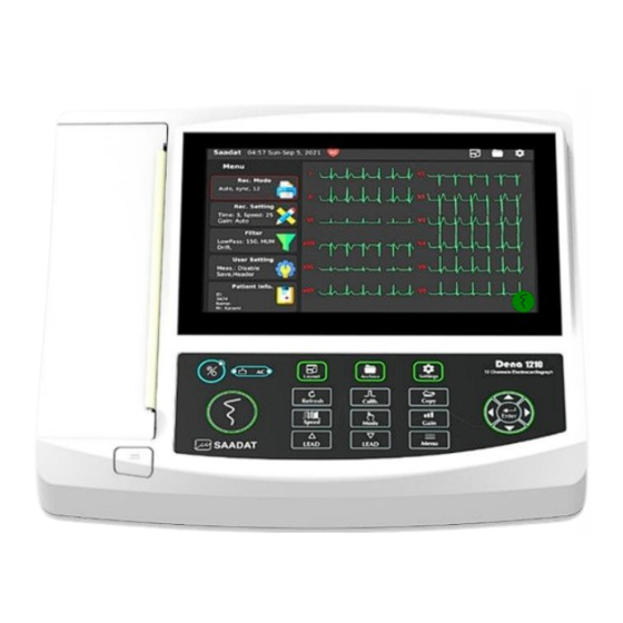
(more information follows). Recorder Release Button: to open the recorder door. Recorder: to load recording paper and record ECG waveforms. Control panel: to control the system operation. (more information follows). Display screen Figure 1-2 DENA 1210 display screen (default) - Page 15 Chapter 1: Introduction DENA 1210 has a TFT color screen. The 12-wave ECG waveform, HR numerical value, patient name and ID, date and time, device status and system messages are displayed on this screen. The screen can be divided into three parts:...
-
Page 16: Control Panel
Device notification and error messages are displayed in yellow box at the bottom of this area. Control panel The Dena 1210 electrocardiograph is designed so that the operator can easily work with it using several keys along with a touch screen. Figure 1-4 shows the functional keys and indicators of the Dena 1210 electrocardiograph. - Page 17 Used to enter menus or select the desired option. Enter Warning • Before starting work with the Dena 1210 electrocardiograph, first check all the keys and make sure that they work correctly. • Do not use sharp objects to touch the screen.
-
Page 18: Recorder
Chapter 1: Introduction Recorder Warning • Use only the record paper recommended by the manufacturer, otherwise the quality of the record may be poor and the thermal head may be damaged. • Only 210 mm heat-sensitive record paper should be used. •... - Page 19 Chapter 1: Introduction 3. Place the other side of the paper roll in its proper place. Open the paper roll to leave some of it out of the recorder. 4. Close the recorder door. Warning • Do not open the recorder while the recorder is operating. This can damage it. •...
- Page 20 Chapter 1: Introduction Note • • If there is paper or foreign object on the sensor, it cannot work properly. Therefore, if you see a foreign object on the sensor, remove it and clean the sensor. • Be careful when loading the paper in the recorder. Avoid damaging the thermosensitive print head.
-
Page 21: Bottom Panel
• If the battery discharge time is less than 1 hour, the battery is defective and contact after-sales service to replace it. • DENA 1210 will turn off automatically if the battery power is too low. When the electric power is going out, the message "BATTERY LOW" will be displayed. -
Page 22: Rear Panel
Chapter 1: Introduction Note • Make sure the battery indicator light is on. If the battery indicator does not light up, check the local power supply and power cord connection. If this problem persists, contact after-sales service. • The battery needs to be charged after transport or storage. If in this case you try to turn on the device without connecting the power cable, the device cannot be turned on due to insufficient charge. -
Page 23: System Settings
Chapter 2: System settings 2) System settings... -
Page 24: General Information
• Before recording, it is better to adjust the device according to your desired conditions. Figure 2-1 Main menu (full screen) The Dena 1210 electrocardiograph has a flexible configuration. By default, the Menu is on the left side of the screen. By changing the display mode to "Full screen" (by touching the option or its key in the control panel), the Menu section is hidden and the waveforms are drawn in full screen. -
Page 25: Recording Mode Menu
Chapter 2: System settings Recording Mode menu By selecting Rec. Mode from the main menu, different recording modes can be set as shown. Figure 2-2 Rec. Mode menu: (a) Auto3+1, (b) Auto 6, (c) Manual 6+2, (d) Manual 12. - Page 26 Chapter 2: System settings Figure 2-3 Rec. Mode menu: Rhythm Based on the option selected in the Rec Type section, the following modes can be selected: • Auto: o Rec. Format: 3+, 6, 6+ and 12 modes can be selected for recording. Selected option is displayed in the Rec.
-
Page 27: Rec. Setting Menu
Chapter 2: System settings Rec. Setting menu By selecting Rec Setting from the main menu, the following window will appear: Figure 2-4 Rec. Setting menu The following settings are applicable in this menu: • Rec Time (Auto mode only): This option is used to set the recording time of leads in Auto mode, the available options are 3-12 seconds. -
Page 28: Filter Menu
Chapter 2: System settings Filter menu By selecting Filter from the main menu, the following window will appear: Figure 2-5 Filter menu The following settings are applicable in this menu: • Low Pass: Available options are Off and 25, 35, 75, 150 Hz. This filter is used to remove muscle noise and high frequency noise. - Page 29 Chapter 2: System settings Warning • The use of 25, 35, and 75 Hz Low Pass filters may reduce the amplitude of the heart signal and omit some useful signal details. • If you turn on the local power noise cancellation filter, in proportion to the selected frequency, its third harmonic will also be removed.
-
Page 30: User Setting Menu
Figure 2-6 User Setting menu The following settings are applicable in this menu: • Pace: Available options are Off and On. DENA 1210 detects and rejects pacemaker- generated signals from ECG signal, so that they will be ignored in determining heart rate. -
Page 31: Patient Information
Chapter 2: System settings Patient Information By selecting Patient Info from the main menu, the following window will appear: Figure 2-7 Patient Information menu Note • To enter textual or numeric information, the appropriate virtual keyboard (Figure 2- 8) opens. •... - Page 32 Chapter 2: System settings Warning • Enter patient information correctly. Otherwise, the stored information may be confused with other patients' information. • Information such as age and gender affect the accuracy of the results of the Measurement feature. Figure 2-8 Virtual keyboard: (a) Letters, (b) Numbers and symbols , (c)Numbers...
-
Page 33: Setting Menu
Chapter 2: System settings Setting menu Selecting Setting from the Header area will open this menu. On the left side of the screen, access to the settings of different sections is provided. By selecting each, the settings for that option are displayed. Date &... - Page 34 Chapter 2: System settings Display: • Brightness: The amount is proportional to the length of the green bar from 5 to 100%. • Theme: It has two choices, Dark and Light. By selecting the Dark option, the color of all menus and the background of the signal display will be dark. By selecting the Light option, the menus and the background of the signal display are displayed in bright color.
- Page 35 Chapter 2: System settings Recording: At the top of this page, you can select the internal thermal recorder or external printer. Touching the green Rec Test key will draw a test signal. The Periodic Recording Interval section is used to enable / disable periodic mode. By setting the Periodic Interval other than off, the intervals of the periodic recordings are determined and the Periodic Repetition option is available to adjust the number of repetitions of the periodic recordings.
- Page 36 Chapter 2: System settings Network: Used to view and apply network settings. Figure 2-12 Network setting menu Update: Update the software, or restore the device settings to the default state, and clear the memory on this page. By default, only the Update section is enabled. By pressing the password keys, the Reset option will also be available.
- Page 37 Chapter 2: System settings General: The name of the hospital can be entered on this page. Sound setting and Smart Record are also done on this page. Smart Record: By activating this option, according to the range of signals in each group of leads, the device will automatically allocate the appropriate space to each lead in the group.
- Page 38 Chapter 2: System settings Language: On this page, you can select the language of the device from the فارس ی English options. By selecting ,فارسیall texts in the device menus are displayed in Persian language. By selecting English, these texts are displayed in English. Figure 2-16 Language setting menu About: Selecting this option will open the following window with the details of the device and the name and contact information of the manufacturer.
-
Page 39: Patient Preparation
Chapter 3: Patient preparation 3) Patient preparation... -
Page 40: Actions Before Recording
Chapter 3: Patient preparation Actions before recording • Give the patient enough time to relax after lying on the bed. • If necessary, shave the hair where the electrodes are placed on the patient's skin. • The connection of the electrodes to the skin should be cleaned with alcohol or a solution of soap and water and then dried. -
Page 41: Connection Of The Limb Electrodes
Chapter 3: Patient preparation • When you connect the cables and electrodes, make sure that no metal part is in contact with the safety ground. • Check that all ECG electrodes are properly attached to the patient's body. • Interference from non-grounded devices near the patient or ESU (Electrosurgical Unit) can cause inaccurate ECG waveforms. -
Page 42: Detection Of Electrode Disconnection
Chapter 3: Patient preparation Detection of electrode disconnection DENA 1210 continuously monitors the connection status of the electrodes, and in the event of a disconnection, displays the relevant messages at the location of the signals on the screen (Figure 1-3). -
Page 43: Color Codes And Labels Of Electrodes
Chapter 3: Patient preparation Color codes and Labels of electrodes There are different labels and color codes for ECG electrodes according to IEC and AHA standards. Select ECG cable with regard to acceptable standard in your hospital. • IEC standard: Site for electrodes Symbol for electrodes Color code for electrodes... -
Page 44: Lead Placement Diagram
Chapter 3: Patient preparation Lead placement diagram Figure 3-4 Lead placement diagram... -
Page 45: Recording Operation
Chapter 4: Recording Operation 4) Recording Operation... -
Page 46: Recording Types
Chapter 4: Recording Operation Note • Refer to System settings chapter to view the recording settings. • Recording starts by pressing the Start/Stop key and during this operation, the color of the key changes on the screen and the lock symbol appears in the background. As long as the screen is in this mode, all keys and menus except the Start/Stop key (and the Lead▼... -
Page 47: Rhythm Recording
Chapter 4: Recording Operation Rhythm Recording By selecting Rhythm from the Rec Mode menu using the keyboard or by touching the screen, the waveform corresponding to the selected rhythm lead(s) (one to three leads) is drawn on the screen. In this mode, according to the number of selected leads, the screen is divided into one to three parts and displays one of the leads in each part. -
Page 48: Periodic Recording
Chapter 4: Recording Operation Periodic Recording This mode is used to generate consecutive records with a time interval and specified repetition. Recording in this mode is always done according to the latest settings of the device and changing the settings does not interfere with this operation. Also, the number and time remaining until the next record is always displayed in the header area. -
Page 49: Ecg Analysis And Measurement
Chapter 5: ECG analysis and measurement 5) ECG analysis and measurement... -
Page 50: General Information
In order to automatically analyze the ECG signal, the analysis and interpretation software of the University of Glasgow (The Glasgow Program) has been added to DENA 1210. This software helps in more accurate diagnosis of the disease in two parts: Measurement and Interpretation. -
Page 51: Heart Axis
Chapter 5: ECG analysis and measurement Heart Axis The cardiac vector (Heart axis) is the average sum of the electrical forces inside the heart, or in other words, the angle of the result of the vector of the heart's electrical activity. The electric vector can be calculated for P, QRS and T waves. -
Page 52: Reported Parameters In Details Mode
Chapter 5: ECG analysis and measurement Reported parameters in Details mode In this mode, the details of 12 leads are reported in addition to the Global mode. These details are given in table 5-2. Table 5-2 Reported parameters in Details ECG parameters Description P Dur [ms]... - Page 53 Chapter 5: ECG analysis and measurement By selecting one of the two modes Global or Detail and recording the results, it will be printed as a table at the end of the record paper. The difference between Global and Detail modes is in the detailed expression of the ECG signal parameters (Measurement section) and the results of the Interpretation section are exactly the same in both cases.
- Page 54 Chapter 5: ECG analysis and measurement Each Interpretation phrase begins with a special letter that indicates the following: {H}: Indicates the title of report and is written in first line. {R}: Corresponds the rhythm interpretation. {D}: Indicates the details of the signal analysis and identifies the diagnostic terms. {S}: Shows a summary of the signal analysis status.
-
Page 55: Data Management
Chapter 6: Data management 6) Data management... -
Page 56: General Information
All ECG recorded data in Auto and Rhythm modes, as well as Periodic recordings, will be stored in the internal memory of DENA 1210 for future reference. For this purpose, the Save option in User settings menu should be Enable. In case of disabling the Save option no data is saved in the Archive. - Page 57 Chapter 6: Data management The following information about each saved record can be seen in the Archive window: • Date and time of recording • Patient ID (if any) • Patient name (if any) • Filter settings at the time of recording •...
-
Page 58: Transfer Menu
Chapter 6: Data management Transfer menu By selecting the "Transfer" section in the Setting menu, this window will appear: Figure 6-2 Transfer setting menu On the right side of the screen, records stored in memory are displayed and the user can select the desired items. -
Page 59: Online Data Transfer To Pc
Chapter 6: Data management Online data transfer to PC The Dena 1210 electrocardiograph has the ability to transfer the information of the signals being drawn on the screen to a personal computer via the USB port of the Device type. After installing the relevant software on the personal computer, by connecting the port to the computer via a USB cable, it is possible to transfer data online. - Page 60 Chapter 6: Data management...
-
Page 61: Care And Cleaning
Chapter 7: Care and Cleaning 7) Care and Cleaning... -
Page 62: System Check
Note • To ensure maximum battery life, let the DENA 1210 runs on the battery, at least once a month, until it turns itself off and then recharge the battery. • If you find any damage in DENA 1210, stop using it on patient, and contact the biomedical engineer of the hospital or the manufacturer After Sales Service. -
Page 63: Maintenance
Chapter 7: Care and Cleaning Maintenance Note • It is recommended that the device be calibrated once a year by the manufacturer, but calibration is mandatory every 2 years. • The life of the device is 10 years. • The hospital can also request a calibration whenever the accuracy of the device is in doubt. -
Page 64: Cleaning & Disinfection
• Allow the device to dry completely before making connections. Make sure all connections are secure before using the system. Note • DENA 1210 and accessories should be kept away from dust. • Do not use detergents that contain ammonia or acetone. • Most cleaning agents must be diluted before use. -
Page 65: Recorder
Chapter 7: Care and Cleaning Recorder Accumulation of paper powder or foreign matter between the thermal head and platen roller deteriorates the print quality. Clean the head elements and platen roller surface using alcohol and a cotton swab. Wait until the alcohol dries then close the recorder door. Warning •... - Page 66 Chapter 7: Care and Cleaning The following table summarizes the methods of cleaning, disinfecting and sterilizing the various parts of the device: Device arts Single-use Cleaning Disinfection Sterilization External surface In-between patients and as In-between patients and To avoid extended required wipe gently using a as required use damage...
-
Page 67: Preventive Maintenance
It should be noted that PM checklist only is used to perform systematic inspection of the equipment and will not guarantee their correct function. Pooyandegan Rah Saadat Co. Form No. : PL-F-33-V1 PM Form (DENA 1210 Electrocardiograph ) State: City: Healthcare center:... - Page 68 Chapter 7: Care and Cleaning...
-
Page 69: Troubleshooting And Error Messages
Chapter 8: Troubleshooting and Error messages 8) Troubleshooting and Error messages... -
Page 70: Troubleshooting
Troubleshooting guide is intended to help users to solve minor problems caused by incorrect use of the DENA 1210 or failure of accessories. When you face any problem, please ensure that you have followed all actions mentioned in Solution column before you contact After- Sales Services. - Page 71 Chapter 8: Troubleshooting and Error messages ● Patient has stress or placed High frequencies and muscle in an uncomfortable condition. ● Relax the patient. ● Patient feels cold and starts artifacts make ECG signal ● Warm the patient with a noisy.
-
Page 72: Error Messages
Chapter 8: Troubleshooting and Error messages Error messages Message Cause Solution Remarks Leads Error Messages Make sure that message Lead R is not properly CHECK R mentioned electrode is displayed white connected to patient. properly connected. color on the screen. Make sure that... - Page 73 Chapter 8: Troubleshooting and Error messages Message Cause Solution Remarks 1- Turn the system off and on. 2- Make sure that the print head battery is sufficiently message voltage is low. Head Low Vol charged. displayed white 2- The battery voltage If the problem still color on the screen.
- Page 74 Chapter 8: Troubleshooting and Error messages...
-
Page 75: Technical Specifications
Chapter 9: Technical specifications 9) Technical specifications... - Page 76 Chapter 9: Technical specifications CLASSIFICATION Protection against electroshock Class I, Type CF , defibrillation-proof applied part Mode of operation Continuous operation equipment Harmful Liquid Proof Degree Ordinary equipment, (without Liquid Proof) Method of sterilization and disinfection Refer to Care and cleaning chapter for detail. Not suitable for use in the presence of a flammable anesthetic Safety in presence of anesthetic mixture mixture with air or with oxygen or nitrous oxide.
- Page 77 Chapter 9: Technical specifications ECG Storage Internal Memory Up to 500 Records Recorder Model SAADAT Thermal Printer Print Method Thermal dot line printing Dots per line 1726 dots 40 dots/mm (Horizontal) @ 25 mm/sec Resolution 8 dots/mm (Vertical) Printing Speed 6.25, 12.5, 25, 50 mm/s...
- Page 78 Chapter 9: Technical specifications...
-
Page 79: Appendix 1: Accessories
Appendix 1: Accessories Appendix 1: Accessories... - Page 80 Appendix 1: Accessories Warning • The accessories listed below are specified to be used for DENA 1210. Manufacturer does not take responsibility for any possible hazard to the patient or device if other accessories are used. • Use only the manufacturer recommended ECG cable. Other ECG cables and leads may cause improper device performance, patient injury and inadequate protection during defibrillation.
-
Page 81: Appendix 2: System Parameters
Appendix 2: System parameters Appendix 2: System parameters... - Page 82 Appendix 2: System parameters ITEM SELECTION DEFAULT Patient Information Menu Name Blank Blank Years/Months Years Gender Male/Female/None None Weight Kg/lb. Height cm/Foot Physician Name Blank A+/A-/B+/B-/AB+/AB-/O+/O-/ Blood Type Unknown Unknown Rec. Mode Rec. Type Auto, Manual, Rhythm Auto Auto / Manual Modes 3+, 6, 6+, 12 I, II, III, aVR, aVL, aVF,...
- Page 83 Appendix 2: System parameters ITEM SELECTION DEFAULT HUM Filter ON/ OFF Drift Filter ON/ OFF EMG Filter ON/ OFF User Setting Menu Save ON/ OFF Pace ON/ OFF Header ON/ OFF Meas. & Interp. Global/Details/OFF Setting Menu Date & Time Date, Time Christian Display...
- Page 84 Appendix 2: System parameters...
-
Page 85: Appendix 3: Electro-Magnetic Compliance
Appendix 3: Electro-magnetic compliance Appendix 3: Electro- magnetic compliance... - Page 86 DENA 1210 is used in the electromagnetic environment specified. • To prevent EMC effect on DENA 1210, the system should not be used adjacent to or stacked with other equipment and that if adjacent or stacked use is necessary, the equipment should be observed to verify normal operation in the configuration in which it will be used.
- Page 87 Guidance and manufacturer's declaration – electromagnetic immunity The DENA 1210 electrocardiograph is intended for use in the electromagnetic environment specified below. The customer or the user of the DENA 1210 electrocardiograph should assure that it is used in such an environment.
- Page 88 Guidance and manufacturer's declaration – electromagnetic immunity The DENA 1210 electrocardiograph is intended for use in the electromagnetic environment specified below. The customer or the user of the DENA 1210 electrocardiograph should assures that it is used in such an environment.
- Page 89 Appendix 3: Electro-magnetic compliance Test specifications for ENCLOSURE PORT IMMUNITY to RF wireless communications equipment Test Distance Service IMMUNITY lation frequency power TEST LEVEL (MHz) (MHz) (V/m) 380- TETRA ulse odul tion 18 Hz 430- GMRS 460, FRS 460 ±5 KHz deviation 1 KHz sine ulse odul...
- Page 90 Appendix 3: Electro-magnetic compliance...
-
Page 91: Appendix 4: The Glasgow Program
Appendix 4: The GLASGOW program Appendix 4: The GLASGOW program... - Page 92 Appendix 4: The GLASGOW program ATRIAL ABNORMALITIES • Possible right atrial abnormality • Consider left atrial abnormality • Possible right atrial abnormality consistent with pulmonary disease • Possible left atrial abnormality • Possible biatrial enlargement QRS AXIS DEVIATION • Indeterminate axis •...
- Page 93 Appendix 4: The GLASGOW program • WPW pattern – probable left posteroseptal accessory pathway • WPW pattern – probable left posterolateral accessory pathway HYPERTROPHY LEFT VENTRICULAR HYPERTROPHY • Left ventricular hypertrophy • Possible left ventricular hypertrophy • Left ventricular hypertrophy, possible digitalis effect •...
- Page 94 Appendix 4: The GLASGOW program • Small lateral Q waves noted: probably normal ECG • Abnormal Q waves of undetermined cause • Lateral Q waves may be due to cardiomyopathy • Q waves may be due to cardiomyopathy ANTEROSEPTAL MYOCARDIAL INFARCTION STATEMENTS •...
- Page 95 Appendix 4: The GLASGOW program • Septal QRS changes may be due to corrected transposition • QRS changes in V2 probably due to LVH but cannot rule out septal infarct • Poor R wave progression – cannot rule out septal infarct •...
- Page 96 Appendix 4: The GLASGOW program MISCELLANEOUS LOW QRS VOLTAGES • Low QRS voltages in limb leads • Low QRS voltages in precordial leads • Generalized low QRS voltages TALL T WAVES • Tall T waves – consider acute ischemia or hyperkalemia •...
- Page 97 Appendix 4: The GLASGOW program • • Probable ventricular tachycardia Possible junctional bradycardia • • Wide QRS tachycardia A-V dissociation • • Accelerated idioventricular rhythm Undetermined rhythm • • Possible idioventricular rhythm Regular supraventricular rhythm • • Possible atrial flutter Irregular supraventricular rhythm •...
Need help?
Do you have a question about the DENA 1210 and is the answer not in the manual?
Questions and answers