Table of Contents
Advertisement
Quick Links
Advertisement
Table of Contents

Subscribe to Our Youtube Channel
Related Manuals for Saadat Dena 350


Summary of Contents for Saadat Dena 350
- Page 1 SAADAT Co. User Manual Dena Electrocardiograph Dena 350 D00718-4.2...
- Page 2 POOYANDEGAN RAH SAADAT CO. No. 4, 1st East St., Ettehad Blvd., Damavand St., TEHRAN, IRAN. Post box: 1658916599 Tel: +98 21 77960719, +98 21 77962181 Fax:+98 21 77964239 Customer Services: Tel: +98 21 73098000, +98 21 77798910 Cell: +98 912 1977157...
-
Page 3: Table Of Contents
Contents Table of Contents Manual Purpose Explanations of the used expressions in this Manual Explanations of the symbols in the Manual and device Section 1 General Warnings…………………………………………………..General Warnings………………………………………………………………... Section 2 System Configuration……………………………………………….. General …………….…………………………………………………………….. System Description……………………………………………………………..ECG Electrodes Connection……………………………………………………. Section 3 Device Setting…………………………………………………………... -
Page 4: Manual Purpose
Manual Purpose Manual Purpose This manual provides the instructions necessary to operate Electrocardiograph device based on its intended use. Observance of this manual is a prerequisite for proper operation and ensures patient and operator safety. If you have any question about the device, please contact our customer service. -
Page 5: Explanations Of The Used Expressions In This Manual
Explanations of the used expressions in this Manual Explanations of the used expressions in this Manual A WARNING symbol advises against certain actions or situations that could result in personal injury or equipment damage. A NOTE symbol provides useful information and recommendations about device function. -
Page 6: Explanations Of The Symbols In The Manual And Device
Explanations of the symbols in the Manual and device Explanations of the symbols in the Manual and device Symbol Definition Consult user manual of the monitor and pay attention to the warnings and cautions. For protection against defibrillator, use only manufacturer recommended accessories. -
Page 7: Section 1 General Warnings
Chapter 1. General Warnings Chapter 1. General Warnings Please refer to this section for overall safety information. -
Page 8: General Warnings
Chapter 1. General Warnings 1-1 General Warnings Electrocardiograph system is intended to be used only by qualified medical staff. Before use, carefully read this manual and directions for use of any accessories. The electrocardiograph is intended for use only as an adjunct in patient assessment. - Page 9 Chapter 1. General Warnings Do not touch the patient, bed or devices nearby during defibrillation. The electrocardiograph and devices connected to it should form an equipotential body to ensure effective grounding. The physician shall consider all well-known side-effects when using the electrocardiograph. To prevent the environment pollution, the device and accessories (e.g.
- Page 10 Chapter 1. General Warnings To prevent EMC effect on the electrocardiograph, it should not be used adjacent to or stacked with other equipment and that if adjacent or stacked use is necessary, the system should be checked for normal operation in the configuration in which it will be used. If any liquid is spilled on the system or accessories, immediately turn off the system and wipe up it by a soft cloth and turn on the system after at least 30 minutes.
-
Page 11: Section 2 System Configuration
Chapter 2. System Configuration Chapter 2. System Configuration Dena350 electrocardiograph system is capable of: _ Displaying 12-lead ECG waveform _ Displaying Rhythm-lead waveform separately on the screen _ 3-channel waveform recording _ Data storage in Internal and External memory _ Displaying and printing stored data... - Page 12 Chapter 2. System Configuration 2- 1 General Information System is equipped with 5 inch color TFT, touch screen, recorder and built-in battery. Dena350 is a small, light-weight and portable Electrocardiograph device and can be used anywhere. Environment: Temperature working 5~40º C Temperature of Transport and -25 ~60º...
-
Page 13: System Description
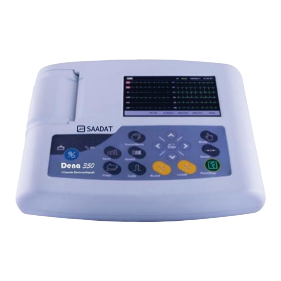
Chapter 2. System Configuration 2- 2 System Description 2-2-1-Top Panel Figure 2-1 Top Panel Display Screen: ECG waveforms, patient information, messages, etc. are displayed on this screen (See Display Screen for details). Recorder: to load recording paper and print ECG waveforms. Control panel: to control the system operation (See Control Panel for details). - Page 14 Chapter 2. System Configuration Display Screen Dena350 is equipped with a TFT color screen. All 12-lead ECG waveform, HR value, Patient ID, Date and Time, system and battery operating status, error and informative messages are displayed on the screen. The screen is divided into three areas: Header area (Figure 2-2) Waveform / Menu area (Figure 2-2), Messages area (Figure 2-2).
- Page 15 Chapter 2. System Configuration All electrodes connection is checked continuously by the system and in case of improper connection, the related message will appear in this area in red. 2- Informative and system error messages area (Figure 2-2). The system messages are displayed in white background and red text. (Refer to Appendix III for the system messages).
- Page 16 Chapter 2. System Configuration Control Panel Dena350 is designed in such a way that user can easily perform operations by using keys and touch screen. 1-On/Off: Press to turn on or off the device. 2-Sens: Use to adjust the amplitude of ECG waveform on the screen and recording paper. 3- Copy: Press to print the last recorded data.
- Page 17 Chapter 2. System Configuration Before using the electrocardiograph, check function of all keys and make sure that it is in proper working order. Indicators The POWER switch (On/Off) is located on the control panel (in Figure 2-3- ). There are two indicators for power and battery on the control panel.
- Page 18 Chapter 2. System Configuration 2-2-2-Bottom Panel Figure 2-4 Bottom Panel Speaker outlet Battery Compartment: For loading the battery. 2-2-3-Peripheral Connectors Figure 2-5 Rear Panel Equipotential grounding terminal. Power Supply jack: 100-240 VAC,2- 0.8 A 50/60 Hz.
- Page 19 Chapter 2. System Configuration The following connectors are located at the left side of the device: Figure 2-6 Side Panel\Left Recorder Release Button: to open the recorder door. Connector of ECG cable The following connectors are located at the right side of the device: Figure 2-7 Side Panel\right USB Device connector: for transferring data to pc software.
- Page 20 Chapter 2. System Configuration 2-2-4-Built-in Battery Electrocardiograph is equipped with a rechargeable battery. The battery will charge automatically once you connect the system to the AC INPUT (whether the device is on or off).When the battery is fully discharged, it takes about 4 hours to charge it again.Afully-charged battery allows an operating time of minimum 8 hours.
- Page 21 Chapter 2. System Configuration 2-2-4-1-Battery placement Put battery in compartment which placed on the bottom plane first,then connect battery 2- wire female connector to the male connector on the charger board.Then fasten 4 fixing screws size3 located on the door to bottom plane. It is recommended to use the same battery with below specification.
-
Page 22: Ecg Electrodes Connection
Chapter 2. System Configuration 2- 3 ECG Electrodes Connection ECG cable consists of two parts: main cable that is connected to the device and lead wires that are connected to the patient Use only one type of electrode on the same patient to avoid variations in electrical impedance. - Page 23 Chapter 2. System Configuration Connection of the Limb Electrodes 4 electrodes of 10 ECG electrodes are attached to the limbs. Reference lead is the electrode connected onto the right leg. Before connecting electrodes: 1- Prepare the patient’s skin. ■The skin is a poor conductor of electricity, therefore preparation of the patient's skin is important to facilitate good electrode contact to skin.
- Page 24 Chapter 2. System Configuration The chest electrodes of 12-lead ECG should be placed in the following sites: ● C1 (V1): Fourth intercostal space at the right margin of the sternum ● C2 (V2): Fourth intercostal space at the left margin of the sternum ●...
- Page 25 Color code for electrodes Right arm White Left arm Black Right leg Green Left leg Brown/Red Brown/ Yellow Brown/ Green Chest Brown/ Blue Brown/ Orange Brown/ Violet For SAADAT ECG cables, labels and color codes according to IEC standard is used.
- Page 26 Chapter 2. System Configuration Lead Placement Diagram Figure 2-10 Lead placement diagram...
-
Page 27: Section 3 Device Setting
Chapter 3. Device Setting Chapter 3. Device Setting 3- 1 General Different software menus of the device will be explained in this section. ■For date and time settings, please refer to Menu/System setting/Time and Date. ■For manufacturer information, please refer to Menu/System setting/About. ■... -
Page 28: Main Menu
Chapter 3. Device Setting 3- 2 Main Menu Dena350 has a flexible configuration which can be changed through Main Menu .You can access the Main Menu by pressing Menu key on the control panel or touching Menu on the screen (Figure 3-1). Figure 3-1 Main Menu The Main menu consists of four options;“User Setting”, “System Setting”, “Patient Info”... - Page 29 Chapter 3. Device Setting The following parameters can be set in this menu: Date/Time To set date and time as shown in the figure below. Figure 3-3 Date/Time Setting Menu Calendar:Available options are Solar and Christian. Date:To set the current date. Time:To set the current time.
- Page 30 Chapter 3. Device Setting Factory Setting: By selecting this option, you can access the following window. Only manufacturer’s authorized personnel have access to this menu. Figure 3-5 Factory Code About:By selecting this option, you can view product and manufacturer information as shown in the figure below Figure 3-6 About Menu ...
-
Page 31: User Setting Menu
Chapter 3. Device Setting 3-4 User Setting Menu By pressing User Setting in the Main menu, you can access User Setting Menu (Figure 3-7). Figure 3-7 User Setting Menu The following parameters can be set in this menu: Rec Mode: Available options are Real Time and Sync in Auto. In the Sync mode, the signals of different leads are recorded simultaneously i.e.recording of all leads starts at the same time. - Page 32 Chapter 3. Device Setting Figure 3-8 Hospital/Ward Beat Volume: Available options are 1, 2, 3 and Off. Select "Off" to mute the heart beat sound. Rhythm Lead: The Rhythm lead can be one of the leads I, II, III,aVL, aVR, aVF, V1, V2, V3,V4, V5 and V6.
- Page 33 Chapter 3. Device Setting Pace Detect: Available options are Off and On. Electrocardiograph system detects and rejects pacemaker-generated signals from ECG signal so that they will be ignored in determining heart rate. If you select On for patients with pacemaker, detected pacemaker signals will be marked on the ECG waveform as a white vertical line.
-
Page 34: Section 4 Patient Information
Chapter 4. Patient Information Chapter 4. Patient Information This section will explain how to manage the patient information. Enter the patient information correctly, otherwise it may be confused with the information of other patients. Touch Patient Info in the Main Menu, or select Patient Info using arrow keys and then press Enter, the Patient Info Menu will appear. - Page 35 Chapter 4. Patient Information Press Cancel to exit from this window and return to the previous menu. Available options are Years and Months. Factory default setting is Years. According to the selected option, year or month of patient age should be entered in this field.
- Page 36 Chapter 4. Patient Information Height Available options are foot and cm. Factory default setting is cm. Enter the patient height and press Save to exit this window. Figure 4-5 Height Press Cancel to exit from this window and return to the previous menu. ...
- Page 37 Chapter 4. Patient Information Figure 4-7 Physician Name Press Cancel to exit from this window and return to the previous menu. Blood Type Press to toggle between A+, A-, B+, B-, AB+, AB-, O+, O- and Unknown. Factory default setting is Unknown. Note: Each time you exit from the Patient Info menu, a message will appear on the screen asking you whether to save changes or not.
-
Page 38: Data Management
Chapter 5. Data Management Chapter 5. Data Management 5- 1 General All ECG recorded data in Auto modes will be automatically stored in the internal memory of the device for future reference. Up to 100 records can be stored in the internal memory. When the memory is full the new data will overwrite the oldest data. - Page 39 Chapter 5. Data Management SD Card: Select to enter the patient ID on SD Card as shown in the figures below. Figure 5-3 SD Card Menu Each record in Show Records Menu contains the following information: Assigned code by the system Patient Name(if any) Patient ID (if any) Date and time of recording...
-
Page 40: Section 6 Recording Operation
1000 samples/s, the signal recovery accuracy of Dena350 Electrocardiograph complies with AAMI EC11 standard requirements. 6- 1 General Dena350 electrocardiograph is equipped with Saadat thermal recorder. Features Optional recording speed (6.25 mm/s, 12.5 mm/s, 25 mm/s, 50 mm/s) ... -
Page 41: Recording Type
Chapter 6. Recording Operation 6- 2 Recording Type 6-2-1- Manual Recording Press Mode key on the screen or the control panel to toggle between Manual 1, Manual 1+1, Manual 2, Manual 2+1and Manual3. Press the Start/Stop key on the control panel to start recording. The recording will continue until you press this key again. - Page 42 Chapter 6. Recording Operation Press Start/Stop key on the control panel to start recording for 3-12 seconds(Refer to section 2 “User Setting Menu”). ■ Auto 1: Select this mode and press the Start/Stop key to start recording. ■ Auto 1+1 :Select this mode and press the Start/Stop key to start recording. In the recording paper the above waveform indicates the waveform of selected lead and the below one is the waveform of Rhythm lead.
-
Page 43: Copy Mode
Chapter 6. Recording Operation You can also perform Automatic and Manual recordings during Periodic recording. For this purpose: 1. Select the recording mode. 2. Press the Start/Stop key. After that recording in the selected mode is finished, Periodic recording will be started automatically. - Page 44 Chapter 6. Recording Operation 6-4-1- Paper loading ■ Press the recorder release button as shown in figure below. Figure 6-1 ■ Place the paper roll in the recorder. Figure 6-2 ■ Place the recorder door. Figure 6-3 ■ Close the recorder door firmly. Figure 6-4...
- Page 45 Chapter 6. Recording Operation Figure 6-5 Do not open the recorder door during recording. This can damage it. The paper detector may not operate properly if covered with foreign object. Therefore, if you find foreign matter on the detector, remove it and clean the detector. During the recorder operation the record paper fed out with constant speed.
-
Page 46: Recorder Cleaning
Chapter 6. Recording Operation If the paper is jammed, open the recorder door and remove the paper. Do not pull the paper out by force. Be careful when loading the paper in the recorder. Avoid damaging the thermal head. Do not touch thermal head. It is recommended to use the paper with colored marks intended to aware user that the paper is near to finish. -
Page 47: Section 7 Patient Safety
Chapter 7. Patient Safety Chapter 7.Patient Safety The electrocardiograph system is designed to comply with the international safety standard requirements for medical electrical equipment. This device has floating inputs (isolated electricity) and is protected against the effects of defibrillation and ESU. If the correct electrodes are used and applied in accordance with the manufacturer instructions, the display screen will recover within 10 seconds after defibrillation. - Page 48 Chapter 7. Patient Safety Grounding the electrocardiograph To protect the patient and hospital personnel, the electrocardiograph system must be grounded. The device is equipped with a detachable 3-wire cable which grounds the instrument to the power line ground (protective earth) when plugged into an appropriate 3-wire receptacle.If a 3- wire receptacle is not available, consult the hospital electricians.
-
Page 49: Section 8 Getting Started
Chapter 8. Getting Started Chapter 8. Getting Started 8-1 Open the package. Open the package and take out the electrocardiograph and accessories carefully. Keep the package for possible future transportation or storage. ■ Check the device for any mechanical damage. ■... -
Page 50: Section 9 Technical Specifications
Chapter 9. Technical Specifications Chapter 9. Technical Specifications CLASSIFICATION Protection against electroshock Class I, Type CF Defibrillation proof (based on IEC 60601-1) Continues operation equipment Mode of operation Ordinary equipment, (without Liquid Proof) Harmful Liquid Proof Degree Refer to chapter 10 for detail Method of disinfection Not suitable for use in the presence of a flammable anaesthetic Safety of anesthetic mixture... - Page 51 Chapter 9. Technical Specifications 16 dots/mm (Horizontal) Resolution 8 dots/mm (Vertical) 6.25, 12.5, 25, 50 mm/s Printing Speed 63 mm Paper Width 56 mm Print Width 12 Lead ECG Waveforms, HR Value, Patient Information, system Printed data model, software version, date and time, paper speed, sensitivity, filter Recording Mode Auto, Manual, Periodic Auto 1, Auto1+1, Auto 2, Auto 2+1, Auto 3, Manual 1, Manual 1+1,...
-
Page 52: Section 10 Care And Cleaning (Pm)
Section 10- Care and Cleaning 10-1 System Check Before using the device, ■ Check if there is any mechanical damage in the system and accessories. ■ Check if the power cable and accessories are firmly connected. ■ Check if all the keys function correctly and are in proper condition. If you find any damage in the electrocardiograph, stop using it on patient, and contact the biomedical engineer of the hospital or the manufacturer After Sales Service. - Page 53 10-2 Cleaning and Disinfection General Points Use only the substances approved by us and methods listed in this chapter to clean or disinfect your equipment. Manufacturer makes no claims regarding the efficacy of the listed chemicals or methods as a means for controlling infection.
- Page 54 External surfaces In-between patients and as required: For cleaning: wipe gently using a moist cloth and warm soapy water or mild detergent and for disinfection use the following recommended agents: ■ Alcohol 70% ■ Isopropyl alcohol ■ N-propanol Display screen In-between patients and as required use clean and soft cloth with neutral detergent and with Isopropyl alcohol may be used for cleaning and disinfection.
-
Page 55: Cleaning
Chapter 10. Care and Cleaning The following table summarizes the methods of cleaning, disinfecting and sterilizing different parts of the device: Single- Device parts Cleaning Disinfection Sterilization In-between patients In-between patients and To avoid extended and as required wipe as required use damage to the External surface of device gently using a moist... - Page 56 Chapter 10. Care and Cleaning 10-3 Preventive Maintenance (PM) To avoid damage to the equipment, disinfection should be performed according to the Hospital Maintenance Schedule. It is recommended that the system is calibrated by manufacturer every year, but it has to be calibrated once every 2 years. In addition, the system lifetime is 10 years.
- Page 57 The preventive maintenance (PM) checklist #PL-F-33 should be completed by responsible individuals of healthcare center. It should be noted that PM checklist only is used to perform systematic inspection of the equipment and will not guarantee their correct function. SAADAT Co. Form No. : PL-F-33 PM Form ( Electrocardiograph )
- Page 58 Chapter 10. Care and Cleaning...
-
Page 59: Section 11 Troubleshooting
Chapter 11. Troubleshooting Chapter11. Troubleshooting Repairing the internal parts of the electrocardiograph must be only done by trained and authorized personnel of After Sale Service; otherwise the manufacturer will not take any responsibility for any possible hazard to the patient and the device. Troubleshooting guide is intended to help users to solve minor problems caused by incorrect use of the electrocardiograph or failure of accessories. - Page 60 Chapter 11. Troubleshooting Problem Possible Cause Solution ● Patient has stress or placed in ● Relax the patient. an uncomfortable condition. ● Check electrodes connection. ● Patient feels cold and starts ●If the problem persists, use High frequencies and muscle artifacts shaking.
- Page 61 Appendix I - Accessory APPENDIX I - Accessory General This section lists the recommended accessories used for the electrocardiograph. The accessories listed below are specified to be used for the electrocardiograph. Manufacturer does not take responsibility for any possible hazard to the patient or device if other accessories are used.
-
Page 62: Appendix I-Accessories
EKG Suction chest electrode, Adult , FIAB, Ref F9009SSC EKG Clamp electrodes, Pediatric, FIAB , Ref F9023SSC P28047 ECG Suction chest electrode, Pediatric-FIAB , Ref F9015SSC P28048 Electrocardiograph Cable,10wires, Banana Ends (SAADAT) P28078 ECG GEL P28045 Recorder Paper, 63 mm , Roll P31017... -
Page 63: Appendix Ii-List Of System Parameters
Appendix II – List of System Parameters APPENDIX II List of System Parameters (Selections and Defaults) Item Selection Default Task bar Menu Manual 1, Manual 1+1, manual1 Manual 2, Manual2+1, Manual3, Recording Mode Auto 1 , Auto1+ 1 , Auto 2 ,Auto 3, Auto 2+1, Auto 3 and Rhythm Sensitivity 2.5, 5, 10, 20 mm/mv... - Page 64 Appendix II – List of System Parameters Item Selection Default System Setting Menu Date/Time 5-60 min-Off Power Off interval:5min Rec Test Factory default About Factory Setting Key Sound On/Off Date/Time Menu Calendar Solar/Christian Christian Date Time About Menu Manufacture Version Website E-mail...
- Page 65 Appendix II – List of System Parameters Item Selection Default Memory Menu Name Search Show Records Menu Page up Page down Cursor up Cursor down Delete Review Review Back Patient Info Menu Name Blank Blank Years/Months Years Gender Male/Female/None None Weight Kg/lb.
-
Page 66: Appendix Iii-Error Messages
Appendix III – Error Messages APPENDIX III Error Messages Message Cause Solution Remarks Leads Error Messages Make sure that Lead RA is not properly The message is displayed in mentioned electrode is CHECK RA connected to patient. red color on the screen. properly connected. - Page 67 Appendix III – Error Messages Message Cause Solution Remarks System Memory Messages The message blinks in red SD Card or inner memory Select record again from load File Error loading problem. the memory page. color on the screen. There is no SD Card in Put a SD Card in the SD The message blinks in red Check SD Card...
-
Page 68: Appendix Iv-Emc
Appendix IV – EMC APPENDIX IV Use only the recommended manufacturer accessory .Using the accessory other than in relevant chapter may cause to increase the EMISSION or decrease the IMMUNITY of system. Measurements can be affected by mobile and RF communications equipment. - Page 69 Appendix IV – EMC Guidance and manufacturer's declaration – electromagnetic immunity The Dena350 Electrocardiograph is intended for use in the electromagnetic environment specified below. The customer or the user of the Dena350 should assure that it is used in such an environment.
- Page 70 Appendix IV – EMC Guidance and manufacturer's declaration – electromagnetic immunity The Dena350 Electrocardiograph is intended for use in the electromagnetic environment specified below. The customer or the user of the Dena350 should assure that it is used in such an environment.
- Page 71 Appendix IV – EMC Recommended separation distances between Portable and mobile RF communications equipment and the Electrocardiograph The Dena350 Electrocardiograph is intended for use in the electromagnetic environment in which radiated RF disturbances are controlled. The customer or the user of the Dena350 can help prevent electromagnetic interference by maintaining a minimum distance between portable and mobile RF communications equipment (transmitters) and the Dena350 as recommended below, according to the maximum output power of the communications equipment.
Need help?
Do you have a question about the Dena 350 and is the answer not in the manual?
Questions and answers