Table of Contents
Advertisement
Quick Links
Advertisement
Table of Contents

Related Manuals for Saadat Dena 640


Summary of Contents for Saadat Dena 640
- Page 1 SAADAT Co. User Manual Dena Electrocardiograph Dena 640 D00850-0...
- Page 2 POOYANDEGAN RAH SAADAT CO. Address: No.4, East First St, Ettehad Blvd. Damavand St, TEHRAN, IRAN Post box: 16765-965 Tel: +98 21 77965038 Fax: +98 21 77964239 Customer Services: Tel: +98 21 77798910 Fax: +98 21 77960761 Cell: +98 912 1977157 Web site: www.saadatco.com...
-
Page 3: Table Of Contents
Table of Contents Explanations of the used expressions in this Manual Explanations of the symbols in the Manual and device Section 1 General Warnings…………………………………………………..General Warnings………………………………………………………………... Section 2 System Configuration……………………………………………….. General …………….…………………………………………………………….. System Description……………………………………………………………..ECG Electrodes Connection……………………………………………………. Section 3 Device Setting………………………………………………………… General …………….…………………………………………………………….. - Page 4 Manual Purpose This manual provides the instructions necessary to operate Electrocardiograph device based on its intended use. Observance of this manual is a prerequisite for proper operation and ensures patient and operator safety. If you have any question about the device, please contact our customer service.
-
Page 5: Explanations Of The Used Expressions In This Manual
Explanations of the used expressions in this Manual A WARNING symbol advises against certain actions or situations that could result in personal injury or equipment damage. A NOTE symbol provides useful information and recommendations about device function. -
Page 6: Explanations Of The Symbols In The Manual And Device
Explanations of the symbols in the Manual and device Symbol Definition Consult user manual of the DENA system and pay attention to the warnings and cautions. The device is IEC60601-1 type CF (Defibrillation proof applied part) equipment. The units displaying this symbol provide an F-type isolated (floating) patient applied part with a high degree of protection against shock and is suitable to use with defibrillator simultaneously. -
Page 7: Section 1 General Warnings
Section 1- General Warnings Please refer to this section for overall safety information. -
Page 8: General Warnings
1-1 General Warnings: Electrocardiograph system is intended to be used only by qualified medical staff. Before use, carefully read this manual and directions for use of any accessories. The electrocardiograph is intended for use only as an adjunct in patient assessment. It must be used in conjunction with clinical signs and symptoms. - Page 9 The operator must check that system and accessories function safely and see that it is in proper working condition before being used (e.g. Date of the last calibration must be valid). Do not use cellular phone in the vicinity of this system. High level of electromagnetic radiation emitted from such devices may result in strong interference with the electrocardiograph performance.
- Page 10 It is possible to increase leakage current when several systems as well as electrocardiograph are connected to the patient. ..simultaneously. Electrocardiograph software is designed in a way that hazards arising from errors in the programmed software are minimized. Do not connect items not specified as parts of the electrocardiograph system.
-
Page 11: Section 2 System Configuration
Section 2- System Configuration Features: Dena is applicable to adult and neonatal patients and capable of: _ Displaying 12-lead ECG waveform _ Displaying Rhythm-lead waveform separately on the screen _ 6-channel waveform recording _ Data storage in internal and external memories _ Displaying and printing stored data Signal recovery accuracy: With regard to maximum frequency bandwidth of 150 Hz and sampling... -
Page 12: General
General Dena is a small, light-weight and portable Electrocardiograph device. It is equipped with a color TFT touch screen, recorder and built-in battery. Environment: Temperature Working 40º C Transport and Storage -25 60º C Humidity 20 90 % Altitude -200 to 3000m Power Supply 100-240VAC, 50/60Hz 60 VA... -
Page 13: System Description
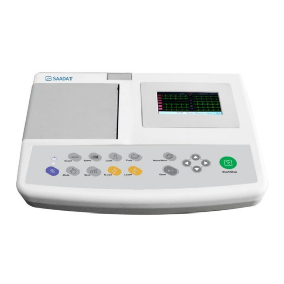
System Description 1. Top Panel Figure 2-1 Top Panel Display Screen: ECG waveforms, patient information, messages and etc. are displayed on the screen (See 2-1 for details). Recorder Release Button: to open the recorder door. Recorder: to load recording paper and print ECG waveforms. Control panel: to control the system operation (See 2-2 for details). - Page 14 2-1 Display Screen Dena is equipped with a TFT color screen. All 12-lead ECG waveform, HR value, Patient name/ID, Date and Time, system operating status, error and informative messages are displayed on the screen. The screen is divided into four areas: Header area (Figure 2-2- ), Waveform / Menu area , Lead error message area (Figure 2-2- ) , informative and system error messages...
- Page 15 Waveform/ Menu Area: Rhythm-lead or 12-lead ECG waveforms are displayed on the screen and their arrangement can not be changed. ECG lead type is displayed in Waveform Area. Message Area: The message area is divided into two parts: 1- Lead error message area: All electrodes connection is checked continuously by the system and in case of improper connection, the related message will appear in this area in red (Figure 2-2- 2- Informative and system error messages area (Figure 2-2-...
- Page 16 2-2 Control Panel Dena is designed in such a way that user can easily perform operations using some keys and touch screen. Press to start/stop ECG recording. Start/Stop Arrow Use to scroll between menus. Keys Press to access Main Menu. Menu Press to print the last recorded data Copy...
- Page 17 Figure 2-3 Control Panel Before using the electrocardiograph, check function of all keys and make sure that it is in proper working order. 2-3 Indicators The POWER switch (On/Off) is located on the control panel ( in Figure 2-3). There are two indicators for power on and batter‟s charge on the control panel.
- Page 18 2. Bottom Panel Figure 2-4 Bottom Panel Handhold: For transporting the device. Battery Compartment: For loading the battery. 3A fast fuse If the device is to be stored for a long period (more than 10 days), the fuse should be removed in order to prevent battery discharge.
- Page 19 The following connectors are located at the right side of the device: Figure 2-6 Side Panel 1-Connector of ECG cable 2-Programmer connector: it should only be used by the manufacturer trained and authorized personnel.
- Page 20 4. Built-in Battery ectrocardiograph is equipped with a rechargeable battery. The battery will charge automatically once you connect the system to the AC INPUT (whether the device is on or off). When the battery is fully discharged, it takes about 5 hours to charge it again. A fully-charged battery allows an operating time of minimum 8 hours.
-
Page 21: Ecg Electrodes Connection
ECG Electrodes Connection ECG cable consists of two parts: main cable that is connected to the device and lead wires that are connected to the patient Use only one type of electrode on the same patient to avoid variations in electrical voltages It is recommended to use silver/silver chloride electrode. - Page 22 When the device is used with electrocautery unit, please note the position of leads. In order to reduce the hazard of burns, the leads should be located away from the electrocautery pen and return electrode. Use intact and clean electrodes only. Electrodes with damaged surface may cause ECG waveform inaccuracy.
- Page 23 Connection of the Limb Electrodes 4 electrodes of 10 ECG electrodes are attached to the limbs. Reference lead is the electrode connected onto the right leg. Before connecting electrodes: 1- Prepare the patient‟s skin. ■ The skin is a poor conductor of electricity, therefore preparation of the patient's skin is important to facilitate good electrode contact to skin.
- Page 24 Connection of the Chest Electrodes Before connecting electrodes: 1- Prepare the patient‟s skin. ■ The skin is a poor conductor of electricity, therefore preparation of the patient's skin is important to facilitate good electrode contact to skin. ■ Shave hair from sites, if necessary. ■...
- Page 25 There are different labels and color codes for ECG electrodes according to IEC and AHA standards. Select ECG cable with regard to acceptable standard in your hospital. IEC Standard: Site for electrodes Symbol for electrodes Color code for electrodes Right arm Left arm Yellow Right leg...
- Page 26 Lead Placement Diagram Figure 2-9 Lead placement diagrams Measurement The purpose of measurement is ECG signal analysis, detection of onset and offset points of P, QRS , T waves and heart axis. They are useful parameters for physician diagnosis to interpret the signal. ECG parameters including QRS and P waves duration and PR, QT and QTc waves interval are measured in millisecond.
- Page 27 Measurable parameters in a heart rate are determined in figure 2-10. Figure 2-10 ECG parameters including duration and intervals The measurement result of ECG signal parameters are recordedon the recorder paper: (Figure 2-11) Figure 2-11 Measurement Table When the signal is saved and the measurement is enabled, the measured parameters table is recordedon the recorder paper while recording the relevant signal.
- Page 28 Time intervals calculation The used method to measure the time intervals is based on analyzing 10-seconds of 12-leads ECG signals. Notch filter (50/60 Hz) is used to remove the artifacts and improve the signal quality and a linear second order band-pass filter with the frequency band (0.8-18 Hz) is used to eliminate the AC interferencece.
- Page 29 Heart Axis calculation Heart axis detection is one of the most important parts of calculating electrocardiography system. This parameter provides the helpful information for medical diagnosis. Heart axis is average of all electrical signals of the heart, in the other word it indicates the consequence vector of heart electrical activities. The electrical axis can be calculated for P, QRS and T waves.
- Page 30 A common method among physician for heart axis calculation is iso-electric method. Iso-electric lead for QRS complex is a lead which the collection of Q, R and S complex amplitudes is near to zero. In this situation, the direction of heart axis will be perpendicular to direction of iso-electric vector. Any combination of 2 limb leads can be used to calculate the electrical axis of heart.
-
Page 31: Section 3 Device Setting
Section 3- Device Settings General Different software menus of the device will be explained in this section. ■ For date and time settings, please refer to System setting/Time and Date. ■ For manufacturer information, please refer to System setting/About. ■ For recording setting, please refer to User Setting. It is recommended that the device is set properly before recording. -
Page 32: Main Menu
Main Menu Dena has a flexible configuration which can be changed through Main Menu. You can access the Main Menu by pressing Menu key on the control panel or touching Menu on the screen (Figure 3-1). Figure 3-1 Main Menu The Main menu consists of four options;... - Page 33 The following parameters can be set in this menu: Date/Time To set date and time as shown in the figure below. Figure 3-3 Date/Time Setting Menu Calendar: Available options are Solar and Christian. Date: To set the current date. Time: To set the current time.
- Page 34 Factory Setting: By selecting this option, you can access the following window. Only manufacturer‟s authorized personnel have access to this menu. Figure 3-5 Factory Code About: By selecting this option, you can view product and manufacturer information as shown in the figure below.
- Page 35 Key/ Touch Sound: To switch ON/OFF the sound of touch or hard keys. Beat Volume: Available options are 1, 2, 3 and Off. Select "Off" to mute the heart beat sound. Hospital/Ward: By selecting this option, you can access the following window and enter hospital or ward name.
-
Page 36: User Setting Menu
User Setting Menu By pressing User Setting in the Main menu, you can access User Setting Menu (Figure 3-9). Figure 3-9 User Setting Menu The following parameters can be set in this menu: Rec Mode: Available options are Real Time and Sync in Auto. In the Sync mode, the signals of different leads are recorded simultaneously i.e. - Page 37 HUM Filter: Press to toggle between 50 Hz, 60 Hz and Off. Select this filter with regard to your local AC frequency. When 50 Hz and 60 Hz are selected, “H50” and “H60” will be displayed respectively on the screen. ...
- Page 38 Measurement option will be used again, you shall refer to User Setting Menu and change the Measurement option to “Enable”. EMG Filter: Press to toggle between On and Off. This filter is used to reject muscular noise. If EMG is set On, “+M” will be displayed on the screen. EMG filter is a low pass filter which varies based on time and the signal slope .The filter bandwidth varies from one sample to another sample proportional to the signal slope.
-
Page 39: Section 4 Patient Information
Section 4-Patient Information This section will explain how to manage the patient information. Enter the patient information correctly, otherwise it may be confused with the information of other patients. Touch Patient Info in the Main Menu, or select Patient Info using arrow keys and then press Enter, the Patient Info Menu will appear. - Page 40 Patient Data Entry Select each item to access the related window. Name Enter the patient name and press Save to exit from this window (Figure 4-2). Up to 14 characters can be input in this field. Figure 4-2 Name Press Cancel to exit from this window and return to the previous menu.
- Page 41 Available options are Years and Months. Factory default setting is Years. According to the selected option, year or month of patient age should be entered in this field. Patient age can be registered in year or month according to the selected option. Enter the patient age and press Save to exit this window.
- Page 42 Press Cancel to exit this window and return to the previous menu. Weight Available options are Kg and 1b. Factory default setting is Kg. Enter the patient weight and press Save to exit this window. Figure 4-5 Weight Press Cancel to exit from this window and return to the previous menu. ...
- Page 43 Press Cancel to exit from this window and return to the previous menu. Physician Name Enter the physician name and press Save to exit this window. Up to 15 characters can be input in this field. Figure 4-7 Physician Name Press Cancel to exit from this window and return to the previous menu.
-
Page 44: Data Management
Section 5- Data Management General After set to Enable of SAVE option in Memory Menu, all ECG recorded data in Auto & Periodic modes will be automatically stored in the internal memory of the device for future reference. This data can be Recall in Memory Menu. Up to 100 records can be stored in the internal memory. -
Page 45: Memory Menu
Memory Menu Select Memory in the Main Menu to access Memory Menu (Figure 5-1). Figure 5-1 Memory Menu ■ Save : When this option is set, all of the recorded signals in Auto & Periodic mode will saved in internal memory of device. The stored data can be recall by Show Records menu. If this option is set to Disable no data recorded. - Page 46 Show All Records: Select to show all saved records in Show Records menu. ID: Select to enter the patient ID as shown in the figures below. Figure 5-3 ID/ Memory Menu Name : Select to enter the patient name as shown in the figures below. Figure 5-4 Name/ Memory Menu ...
- Page 47 If patient name/ID is entered incorrectly, the message “There is no record, change selection” will appear. Figure 5-5 Show Records Menu Each record in Show Records Menu contains the following information: Assigned code by the system Patient Name(if any) Patient ID (if any) Date and time of recording Recording mode: “R”...
- Page 48 Figure 5-6 Review This page contains: ECG waveforms HR value Speed, Gain and recording mode Filter name Patient name and ID Date and time of recording Press Start/Stop key to print the stored ECG signals in the same condition as the recording time.
-
Page 49: Section 6 Recording Operation
With regard to maximum frequency bandwidth of 150 Hz and sampling rate of 1000 samples/s, the signal recovery accuracy of Dena Electrocardiograph complies with IEC 60601-2-25 standard requirements. General Dena electrocardiograph is equipped with Saadat thermal recorder. Features Optional recording speed (6/25 mm/s, 12.5 mm/s, 25 mm/s, 50 mm/s) ... -
Page 50: Recording Type
Recording Type Manual Recording Press Mode key on the screen or the control panel to toggle between Manual 1+1, Manual 3, Manual 3+1 and Manual 6. Press the Start/Stop key on the control panel to start recording. The recording will continue until you press this key again. - Page 51 Automatic Recording Press Mode key on the screen or the control panel to toggle between Auto 1+1, Auto 3, Auto 3+1 and Auto 6. Press Start/Stop key on the control panel to start recording for 3-12 seconds (Refer to section 2 “User Setting Menu”).
-
Page 52: Copy Mode
Rhythm Recording Select Rhythm using the Mode key on the screen or control panel to see ECG waveform of the rhythm lead in four traces. Press Start/Stop key to record according to “Length of Rhythm Rec” (Refer to section 2 “User Setting Menu”). A counter starts from Length of Rhythm Rec and countdown to zero. -
Page 53: Recorder Paper
Recorder Paper Use only heat sensitive recording paper with 110 mm width. Use only the manufacturer recommended record paper, otherwise the recording quality may be poor or the thermosensitive printhead may be damaged. Do not touch the recorder head while recording and immediately after recording because it is so hot and may lead to personal injury including burns. - Page 54 Paper loading ■ Press the recorder release button as shown in figure below. ■ Open the recorder door. ■ Place the paper roll in the recorder awry and push it. ■ Place the other side of the paper roll in the recorder.
- Page 55 ■ Close the recorder door firmly. Do not open the recorder door during recording. This can damage it. The paper detector may not operate properly if covered with foreign matter. Therefore, if you find foreign matter on the sensor, remove it and clean the sensor. During the recorder operation the record paper exits steadily.
- Page 56 It is recommended to use the paper with coloured marks intended to aware user that the paper is near to finish. Otherwise user should ensure that sufficient paper has been fed to the recorder before recording. The following information are printed on the recorder paper: ■...
-
Page 57: Section 7 Patient Safety
Section 7- Patient Safety The electrocardiograph system is designed to comply with the international safety standards requirements for medical electrical equipment. This device has floating input (isolated electricity) and is protected against the effects of defibrillation. If correct electrodes are used in accordance with the manufacturer instructions, the display screen will recover within 10 seconds after defibrillation. - Page 58 Grounding the electrocardiograph To protect the patient and hospital personnel, the electrocardiograph system must be grounded. The device is equipped with a detachable 3-wire cable which grounds the instrument to the power line ground (protective earth) when plugged into an appropriate 3-wire receptacle. If a 3-wire receptacle is not available, consult the hospital electricians.
-
Page 59: Section 8 Getting Started
Section 8- Getting Started 8-1 Open the package. Open the package and take out the electrocardiograph and accessories carefully. Keep the package for possible future transportation or storage. ■ Check the device for any mechanical damage. ■ Check existence of accessories and contents according the following checklist: Electrocardiograph device 1 unit Patient cable... - Page 60 Make sure that the battery indicator lights. If it does not light, check your local power supply and power cable connection. If the problem still exists, contact the After -Sales Services department. The battery needs to be charged after transportation or storage.
-
Page 61: Section 9 Technical Specifications
Section 9- Technical Specifications CLASSIFICATION Protection against electroshock Class I, Type CF , defibrillation-proof applied part Mode of operation Continues operation equipment Harmful Liquid Proof Degree Ordinary equipment, (without Liquid Proof) Method of sterilization and disinfection Refer to chapter 10 for detail. Not suitable for use in the presence of a flammable anaesthetic Safety of anesthetic mixture mixture with air or with oxygen or nitrous oxide. - Page 62 P Duration (ms) QRS Duration (ms) PR Interval (ms) QT Interval (ms) QTc Interval (ms) P/QRS/T Axis (degree) Recorder Model SAADAT Thermal Printer Print Method Thermal dot line printing Dots per line 832 dots 16 dots/mm (Horizontal) Resolution 8 dots/mm (Vertical) Printing Speed 6.25, 12.5, 25, 50 mm/s...
-
Page 63: Section 10 Care And Cleaning (Pm)
Section 10- Care and Cleaning (PM) 10-1 System Check Before using the device, ■ Check if there is any mechanical damage in the system and accessories. ■ Check if the power cable and accessories are firmly connected. ■ Check if all the keys function correctly and are in proper condition. If you find any damage in the electrocardiograph, stop using it on patient, and contact the biomedical engineer of the hospital or the manufacturer After Sales Service. -
Page 64: Cleaning
10 -2 Cleaning Before cleaning the electrocardiograph or the patient cable, make sure that the equipment is switched off and disconnected from the power line. The electrocardiograph system must be kept dust-free. Regular cleaning of the device and the LCD screen is strongly recommended. Please pay special attention to the following items: 1- Don't use strong solvents such as acetone or ammonia. -
Page 65: Disinfection
10-3 Disinfection Examples of disinfectants that can be used for the device are listed below: ■ Hydrogen Peroxide 3% ■ Alcohol 70% ■ Isopropanol ■ Enpropanol To avoid damage to the equipment, disinfection should be performed according to the Hospital Maintenance Schedule. - Page 66 Daily check of the following items is recommended: 1. Accessories intactness (no mechanical damage) 2. Accessories function Weekly check of the following items is recommended: 1. System cleanness 2. System intactness (case, screen, keys, indicators, recorder door and release button) 3.
-
Page 67: Section 11 Troubleshooting
Section 11- Troubleshooting Repairing the internal parts of the electrocardiograph must be only done by trained and authorized personnel of After Sale Service; otherwise the manufacturer will not take any responsibility for any possible hazard to the patient and the device. Troubleshooting guide is intended to help users to solve minor problems caused by incorrect use of the electrocardiograph or failure of accessories. - Page 68 Problem Possible Cause Solution ● Patient has stress or placed in ● Relax the patient. ● Check electrodes connection. an uncomfortable condition. ● Patient feels cold and starts ●If the problem persists, use High frequencies and muscle artifacts shaking. EMG or Lowpass filter. make ECG signal noisy.
-
Page 69: Appendix I-Accessories
Manufacturer does not take responsibility for any possible hazard to the patient or device if other accessories are used. Accessories Table: Accessories Description PRS Part # Man. Part # IEC ECG Cable, 10 wires, Saadat P28041 ECG Clamp electrodes, Adult-FIAB P28042 F9024SSC ... -
Page 70: Appendix Ii-List Of System Parameters
APPENDIX II List of System Parameters (Selections and Defaults) Item Selection Default Task bar Menu Manual 1+1, Manual 3, Auto 3 Recording Mode Manual 3+1, Manual6, Auto 1+1, Auto 3, Auto 3+1, Auto 6, Rhythm Sensitivity 2.5, 5, 10, 20 mm/mV Paper Speed 6.25, 12.5, 25, 50 mm/s User Setting Menu... - Page 71 EMG Filter On/Off Item Selection Default System Setting Menu Date/Time 5-60 min-Off Power Off interval:5min Rec Test Default Factory About Key/Touch Sound On/Off Beat Volume 1, 2, 3, Off Hospital/Ward Blank Date/Time Menu Calendar Solar/Christian Christian Date Time About Menu Manufacture Version Website...
- Page 72 Item Selection Default Memory Menu Save Enable/Disable Disable Show All Record Name Search Show Records Menu Page up Page down Cursor up Cursor down Delete Review Review Back Patient Info Menu Name Blank Blank Years/Months Years Gender Male/Female/None None Weight Kg/lb.
-
Page 73: Appendix Iii- Error Messages
APPENDIX III Error Messages Message Cause Solution Remarks Leads Error Messages Make sure that Lead RA is not properly The message is displayed in red mentioned electrode is CHECK RA connected to patient. color on the screen. properly connected. Make sure that Lead LA is not properly The message is displayed in red mentioned electrode is... - Page 74 Message Cause Solution Remarks System Messages Recorder Error Messages Turn the system off and on. Rec. Software If problem still exists, The message blinks in red color Software error contact the manufacturer„s Error on the screen. After Sales Service. Turn the system off and on. Rec.
- Page 75 Message Cause Solution Remarks If you want to use copy of There’s No There is no copy after The message displays in black last recorded signal, don‟t turning off & on color on the screen. Copy Rec turn off the device Measurement Messages Occurrence of any Find the related error and...
-
Page 76: Appendix Iv-Emc
APPENDIX IV Use only the recommended manufacturer accessory .Using the accessory other than in relevant chapter may cause to increase the EMISSION or decrease the IMMUNITY of system. Measurements can be affected by mobile and RF communications equipment. It should be assured that the Electrocardiograph is used in the electromagnetic environment specified To prevent EMC effect on the Electrocardiograph, the system should not be used adjacent to or stacked with other equipment... - Page 77 Guidance and manufacturer's declaration – electromagnetic immunity The Dena Electrocardiograph is intended for use in the electromagnetic environment specified below. The customer or the user of the Dena should assure that it is used in such an environment. IEC 60601 Compliance Electromagnetic environment - Immunity test...
- Page 78 Guidance and manufacturer's declaration – electromagnetic immunity The Dena Electrocardiograph is intended for use in the electromagnetic environment specified below. The customer or the user of the Dena should assure that it is used in such an environment. Electromagnetic environment – IEC 60601 Compliance Immunity test...
- Page 79 Recommended separation distances between Portable and mobile RF communications equipment and the Electrocardiograph The Dena Electrocardiograph is intended for use in the electromagnetic environment in which radiated RF disturbances are controlled. The customer or the user of the Dena can help prevent electromagnetic interference by maintaining a minimum distance between portable and mobile RF communications equipment (transmitters) and the Dena as recommended below, according to the maximum output power of the communications equipment.
Need help?
Do you have a question about the Dena 640 and is the answer not in the manual?
Questions and answers