Mitsubishi Electric MELSEC-Q Series User Manual
Melsec-q/l anywireaslink master module
Hide thumbs
Also See for MELSEC-Q Series:
- User manual (834 pages) ,
- Reference manual (674 pages) ,
- Programming manual (624 pages)
Table of Contents
Advertisement
Quick Links
Advertisement
Table of Contents
Troubleshooting

Related Manuals for Mitsubishi Electric MELSEC-Q Series


Summary of Contents for Mitsubishi Electric MELSEC-Q Series
- Page 1 MELSEC-Q/L AnyWireASLINK Master Module User's Manual -QJ51AW12AL -LJ51AW12AL...
-
Page 3: Copyright
This document is protected by the law of copyright, whereby all rights established therein remain with the company Mitsubishi Electric Corporation. Reproduction of this document or parts of this document is only permissible within the limits of the legal determination of Copyright Law. Alteration or abridgement of the document is not permitted without the explicit written approval of the company Mitsubishi Electric Corporation. -
Page 4: Safety Precautions
SAFETY PRECAUTIONS (Read these precautions before using this product.) Before using this product, please read this manual and the relevant manuals carefully and pay full attention to safety to handle the product correctly. The precautions given in this manual are concerned with this product only. For the safety precautions of the programmable controller system, refer to the user's manual for the CPU module used. - Page 5 Precautions for using the QJ51AW12AL [Design Precautions] WARNING ● An AnyWireASLINK system has no control function for ensuring safety. ● When connecting a peripheral with the CPU module or connecting a personal computer with an intelligent function module to modify data of a running programmable controller, configure an interlock circuit in the program to ensure that the entire system will always operate safely.
- Page 6 [Installation Precautions] CAUTION ● Use the programmable controller in an environment that meets the general specifications in the user's manual for the CPU module used. Failure to do so may result in electric shock, fire, malfunction, or damage to or deterioration of the product.
- Page 7 [Wiring Precautions] CAUTION ● Individually ground the FG and LG terminals of the programmable controller with a ground resistance of 100 ohms or less. Failure to do so may result in electric shock or malfunction. ● Check the rated voltage and terminal layout before wiring to the module, and connect the cables correctly.
- Page 8 [Startup and Maintenance Precautions] WARNING ● Do not touch any terminal while power is on. Doing so will cause electric shock or malfunction. ● Shut off the external power supply (all phases) used in the system before cleaning the module or retightening the terminal block screws.
- Page 9 Precautions for using the LJ51AW12AL [Design Precautions] WARNING ● An AnyWireASLINK system has no control function for ensuring safety. ● When connecting a peripheral with the CPU module or connecting a personal computer with an intelligent function module to modify data of a running programmable controller, configure an interlock circuit in the program to ensure that the entire system will always operate safely.
- Page 10 [Installation Precautions] CAUTION ● Use the programmable controller in an environment that meets the general specifications in the Safety Guidelines provided with the CPU module or head module. Failure to do so may result in electric shock, fire, malfunction, or damage to or deterioration of the product. ●...
- Page 11 [Wiring Precautions] CAUTION ● Individually ground the FG and LG terminals of the programmable controller with a ground resistance of 100 ohms or less. Failure to do so may result in electric shock or malfunction. ● Check the rated voltage and terminal layout before wiring to the module, and connect the cables correctly.
- Page 12 [Startup and Maintenance Precautions] WARNING ● Do not touch any terminal while power is on. Doing so will cause electric shock or malfunction. ● Shut off the external power supply (all phases) used in the system before cleaning the module or retightening the terminal block screws.
-
Page 13: Conditions Of Use For The Product
CONDITIONS OF USE FOR THE PRODUCT (1) Mitsubishi programmable controller ("the PRODUCT") shall be used in conditions; i) where any problem, fault or failure occurring in the PRODUCT, if any, shall not lead to any major or serious accident; ii) where the backup and fail-safe function are systematically or automatically provided outside of the PRODUCT for the case of any problem, fault or failure occurring in the PRODUCT. -
Page 14: Introduction
INTRODUCTION Thank you for purchasing the Mitsubishi MELSEC-Q or -L series programmable controllers. This manual describes the functions and programming of the QJ51AW12AL AnyWireASLINK master module and LJ51AW12AL AnyWireASLINK master module. Before using this product, please read this manual and the relevant manuals carefully and develop familiarity with the functions and performance of the MELSEC-Q or -L series programmable controller to handle the product correctly. -
Page 15: Relevant Manuals
RELEVANT MANUALS (1) CPU module user's manual Manual name Description <manual number (model code)> QCPU User's Manual (Hardware Design, Maintenance and Inspection) Specifications of the hardware (CPU modules, power supply modules, base units, batteries, and memory cards), system maintenance and inspection, and troubleshooting <SH-080483ENG, 13JR73>... -
Page 16: Table Of Contents
CONTENTS CONTENTS COPYRIGHT ............... 1 PRECAUTIONS REGARDING WARRANTY AND SPECIFICATIONS . - Page 17 Power-on ..............51 Terminating Unit .
- Page 18 APPENDICES Appendix 1 Details of I/O Signals........... 101 Appendix 1.1 Input signals .
-
Page 19: Manual Page Organization
MANUAL PAGE ORGANIZATION In this manual, pages are organized and the symbols are used as shown below. The following illustration is for explanation purpose only, and should not be referred to as an actual documentation. "" is used for screen names and items. The chapter of the current page is shown. -
Page 20: Terms
MELSEC-L series The abbreviation for the Mitsubishi programmable controller MELSEC-L series MELSEC-Q series The abbreviation for the Mitsubishi programmable controller MELSEC-Q series Power cable (24V, 0V) A cable that connects a master module to a 24VDC external power supply Programming tool... -
Page 21: Packing List
PACKING LIST The following items are included in the package of this product. Before use, check that all the items are included. QJ51AW12AL QJ51AW12AL Before Using the Product LJ51AW12AL LJ51AW12AL Before Using the Product... -
Page 22: Chapter 1 Features
CHAPTER 1 FEATURES AnyWireASLINK The AnyWireASLINK is a high-speed and highly reliable system which releases the work site from complicated and incorrect wiring. In this network, sensors at the end of a control system are connected to a programmable controller in the optimum form. -
Page 23: Features
CHAPTER 1 FEATURES Features This section describes the features of the AnyWireASLINK. (1) Flexible wiring The AnyWireASLINK allows flexible connections if the overall cable distance of transmission cables (DP, DN) is within 200m. There is no restriction about, for example, the main line length, station-to-station distance, and number of branches. - Page 24 (4) RAS improvement The system start-up time can be reduced by checking whether a slave module is connected or by detecting an ID setting error.
-
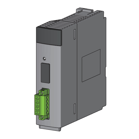
Page 25: Chapter 2 Part Names
CHAPTER 2 PART NAMES CHAPTER 2 PART NAMES This chapter describes the part names of the master module. QJ51AW12AL LJ51AW12AL... - Page 26 Name Description The master module status is indicated by the LEDs. LED name Description Indicates the operating status of the master module. RUN LED (green) ON: Operating normally OFF: Master module error, 5VDC power off, or CPU module stop error Indicates the link status of the master module.
-
Page 27: Chapter 3 Specifications
CHAPTER 3 SPECIFICATIONS CHAPTER 3 SPECIFICATIONS This chapter describes the general specifications and performance specifications and lists the functions, I/O signals, and buffer memory addresses. General Specifications For the general specifications of the master module, refer to the following. "Safety Guidelines" included with the CPU module, base unit, or head module... -
Page 28: Performance Specifications
Performance Specifications 3.2.1 Performance list The following table lists the performance specifications of the master module. Model name Item QJ51AW12AL LJ51AW12AL Transmission clock 27.0kHz Maximum transmission distance (total 200m length) Transmission system DC power supply transmission total frame cyclic system Connection type Bus topology (multidrop system, T-branch system, tree branch system) Transmission protocol... - Page 29 CHAPTER 3 SPECIFICATIONS For slave modules with integrated transmission cables (DP, DN), the length of the transmission cables (DP, DN) is included in the total length. For wiring of 50m or more with 4 wires (DP, DN, 24V, 0V), insert the noise filter for power supply cables between the power supply and cables.
-
Page 30: Number Of Parameters To Set
3.2.2 Number of parameters to set As for the initial settings of a master module and the parameter settings regarding the auto refresh setting, do not set the number of parameters, including those of other intelligent function modules, greater than the number of parameters that can be set in a CPU module. -
Page 31: Communication Performance
CHAPTER 3 SPECIFICATIONS 3.2.3 Communication performance (1) Transmission cycle time The transmission cycle time is the time required for the master module and all the slave modules to update I/O data. The transmission cycle time of the master module is listed in the table below. 64 points (32 input 128 points (64 input Number of... - Page 32 (3) Response delay time The following shows the response delay time of input and output. (a) Input response delay time The figure below shows the time between a signal input to the slave module and the CPU module device turning on/off. The input response delay time is the total of 1) to 5) in the following figure.
- Page 33 CHAPTER 3 SPECIFICATIONS (b) Output response delay time The figure below shows the time between the CPU module device turning on/off and a signal output from the slave module turning on/off. The output response delay time is the total of 1) to 5) in the following figure. Output Output Output...
-
Page 34: Function List
Function List The following table lists the functions of the master module. Item Description Reference item Performs input and output of up to 512 points (256 input points and 256 Bit transmission function Page 62, Section 8.1 output points) between the master module and the slave module. Reads the parameters of a slave module connected to the master module Parameter reading function Page 69, Section 8.8... -
Page 35: List Of I/O Signals
CHAPTER 3 SPECIFICATIONS List of I/O Signals The following table lists the signals input or output between the CPU module and the master module. For details on the I/O signals, refer to Page 101, Appendix 1. Signal direction: Master module to CPU module Signal direction: CPU module to master module Device number Signal name... -
Page 36: List Of Buffer Memory Addresses
List of Buffer Memory Addresses Buffer memory is for data communications between the master module and the CPU module. When the CPU module is reset or the system is powered off and on, the data in the buffer memory are set back to the default (initial values). -
Page 37: Chapter 4 Procedures Before Operation
CHAPTER 4 PROCEDURES BEFORE OPERATION CHAPTER 4 PROCEDURES BEFORE OPERATION This chapter describes the procedure from module mounting/connecting to system operation. Start User's Manual (Hardware Design, Maintenance and Checkbox Inspection) for the CPU Master module mounting/connecting module used Mount or connect the master module. ... - Page 38 Operation mode setting for the master module Page 53, Section 7.1 Set the number of transmission points for the master module. Automatic address detection Page 57, Section 7.3 Save the address of the slave module in the EEPROM of the master module.
-
Page 39: Chapter 5 System Configuration
CHAPTER 5 SYSTEM CONFIGURATION CHAPTER 5 SYSTEM CONFIGURATION This chapter describes the overall configuration, system configuration of the master module, system configuration of AnyWireASLINK, and applicable systems. Overall Configuration 5.1.1 System configuration of the master module This section describes the system configuration of the master module. (1) QJ51AW12AL The following system configuration of the QJ51AW12AL is used for explanation purpose. - Page 40 (b) When connected to the head module Power supply module CPU module Master module END cover...
-
Page 41: System Configuration Of Anywireaslink
CHAPTER 5 SYSTEM CONFIGURATION 5.1.2 System configuration of AnyWireASLINK The following figure shows the system configuration of AnyWireASLINK. QJ51AW12AL LJ51AW12AL General-purpose power supply 24VDC AnyWireASLINK terminating unit ASLINKER ASLINKAMP Cylinder, Sensor head switch, or others 1 Manufactured by Anywire Corporation For the number of connectable slave modules, refer to the following. -
Page 42: Applicable Systems
Applicable Systems This section describes applicable systems. 5.2.1 QJ51AW12AL (1) Applicable modules and base units, and the number of connectable modules (a) Connecting a QJ51AW12AL to a CPU module For the CPU modules, the number of modules, and base units applicable to the QJ51AW12AL, refer to the user's manual for the CPU module used. -
Page 43: Lj51Aw12Al
CHAPTER 5 SYSTEM CONFIGURATION 5.2.2 LJ51AW12AL (1) Number of connectable modules For the number of connectable modules, refer to the following. MELSEC-L CPU Module User's Manual (Hardware Design, Maintenance and Inspection) MELSEC-L CC-Link IE Field Network Head Module User's Manual (2) Precautions for the system configuration (a) Rated output current (5VDC) The total current consumption upon system configuration must not exceed the rated output current (5VDC) of... -
Page 44: Compatible Software Version
Compatible Software Version The system which uses a master module is compatible with the software package as follows. A programming tool is required when a master module is used. Software Version GX Works2 Version 1.98C or later... -
Page 45: Chapter 6 Installation And Wiring
CHAPTER 6 INSTALLATION AND WIRING CHAPTER 6 INSTALLATION AND WIRING This chapter describes the installation and wiring of the master module. Installation Environment and Position of the Master Module For the precautions for the installation environment and position of the master module, refer to the following. ... - Page 46 (2) Transmission cable terminal block Model name Applicable tightening torque 0.2Nm to 0.3Nm MC 1,5/5-STF-3,81 Use the one manufactured by PHOENIX CONTACT GmbH & Co. KG. (For contact, visit www.phoenixcontact.com.) Temperature Classification Name Wire diameter Type Material rating 1.25 UL-listed general-purpose 2-wire cable (VCTF, VCT) 0.75...
-
Page 47: Wiring Precautions
CHAPTER 6 INSTALLATION AND WIRING 6.2.1 Wiring precautions The following shows the wiring precautions in the AnyWireASLINK system. • In the AnyWireASLINK system, signals and power are supplied to a slave module with two types of transmission cables; DP and DN. Therefore, using a stranded wire of 1.25 or larger for the main line is recommended. -
Page 48: Connection Of Slave Modules
6.2.2 Connection of slave modules (1) Connection type Master module Terminating unit Slave module Multidrop Slave module Slave Slave module module Tree-type T-branch • The maximum transmission distance in the AnyWireASLINK stand-alone system is 200m, which is the total cable length including the main line and branch line (branch). (It varies depending on the wire diameter of the transmission cables (DP, DN) or the transmission cable supply current.) •... -
Page 49: Power Supply To The Anywireaslink System
CHAPTER 6 INSTALLATION AND WIRING 6.2.3 Power supply to the AnyWireASLINK system (1) Method of supplying the power to the slave module Connect a 24VDC external power supply to the master module. The power consumed in the internal control circuits of all the slave modules and the external load power connected to non-isolated slave modules are supplied collectively from the 24VDC external power supply connected to the master modules. - Page 50 (a) Description of the condition 1) • Constants related to the non-isolated slave module (Ihin, Iho) For the non-isolated slave module, the current required for the internal control circuit and the connected load is supplied over transmission cables (DP, DN). Ihin(A) = Current consumption of the non-isolated input slave module/I/O combined slave module = Current consumption of the non-isolated input slave module/I/O combined slave module +...
- Page 51 CHAPTER 6 INSTALLATION AND WIRING • Constants related to the isolated slave module (Izdin, Izdo) For the isolated slave module, only the current required for the internal control circuit is supplied over the transmission cables (DP, DN), whereas that for the connected load is supplied from the 24VDC external power supply.
- Page 52 (b) Description of the conditions 2) and 3) • Vm: Supply voltage for the master module Voltage 21.6 to 27.6VDC (24VDC -10% to +15%), ripple voltage 0.5Vp-p or lower Recommended voltage 26.4VDC (24VDC +10%) • V(V): Cable-to-cable voltage drop V(V) = Transmission cable supply current I(A) Cable resistance R() Cable resistance R() = Cable length (m) ...
-
Page 53: Check Before Power-On
CHAPTER 6 INSTALLATION AND WIRING Check before Power-on This section describes the items to be checked before power-on. Check that the master module is mounted or connected correctly. ( User's Manual (Hardware Design, Maintenance and Inspection) for the CPU module used) (... -
Page 54: Terminating Unit
Terminating Unit To ensure more stable transmission quality, connect a terminating unit to the end of a transmission cable (DP, DN). Terminating unit connection Master module Basic Terminating unit The end of a line Main line Important Connect at least one terminating unit for one AnyWireASLINK line. Connect it at the farthest end from the master module. Branch of transmission cables (DP, DN) [Example] Master module... -
Page 55: Chapter 7 Various Settings
CHAPTER 7 VARIOUS SETTINGS CHAPTER 7 VARIOUS SETTINGS Master Module Operation Mode Setting Set the number of transmission points of the master module. ● Making switch settings in Page 54, Section 7.1.2 enables the number of transmission points to be changed and allows the transmission cycle time to be shorten in comparison with that of the default setting. -
Page 56: Switch Setting
7.1.2 Switch setting (1) Setting method Open the "Switch Setting" window to make the setting. Project window [Intelligent Function Module] Module name [Switch Setting] Item Setting value Description 64 Points (input: 32 points, output: 32 points) Set the number of transmission points. Number of 128 Points (input: 64 points, output: 64 points) One transmission cycle time is determined by... -
Page 57: Slave Module Address Setting
CHAPTER 7 VARIOUS SETTINGS Slave Module Address Setting Setting the start number of the addresses assigned for data communications is required for slave modules. An address can be written to a slave module or the address assigned to a slave module can be read through infrared communications using an address writer (manufactured by Anywire Corporation). - Page 58 ● A slave module address is not deleted even when the power supply of a programmable controller or a 24VDC external power supply is turned off. The address is retained until a new address is set when a system is configured. ●...
-
Page 59: Automatic Address Detection Function
CHAPTER 7 VARIOUS SETTINGS Automatic Address Detection Function Automatic address detection is a function to store the IDs (addresses) of the connected slave modules in the EEPROM of the master module. The parameters of the connected devices are automatically updated after storage in EEPROM of the master module followed by detection of IDs (addresses) not set and the same IDs (addresses). - Page 60 (3) Precautions (a) The automatic address detection cannot be performed in the following cases. • Upon an error in the AnyWireASLINK system (Example: Short-circuit, 24VDC external power supply voltage drop) • Within approximately five seconds after the AnyWireASLINK system is powered on or system reset recovery •...
-
Page 61: Interlock Program
CHAPTER 7 VARIOUS SETTINGS 7.3.2 Interlock program The interlock program described here prevents Automatic address detection command (Yn1) from being turned on while parameter access is being executed or the automatic address detection is in progress , allowing proper automatic address detection. The following shows an interlock program in which the start I/O number of the master module is assigned to X/Y00 to X/Y1F. -
Page 62: Automatic Address Detection Execution Timing
7.3.3 Automatic address detection execution timing The following is automatic address detection execution timing. Turn on Automatic address detection command (Yn1) or press and hold the SET switch. Automatic address detection Automatic being executed Automatic address detection flag (X(n+1)4) The LED The LED flashing SET LED... -
Page 63: Automatic Reading Of The System Configuration
CHAPTER 7 VARIOUS SETTINGS Automatic Reading of the System Configuration Man-hours for the parameter setting can be reduced by automatically reading the information of the slave modules connected in the AnyWireASLINK system. Project window [Intelligent Function Module] Module name [AnyWireASLINK Configuration] For the AnyWireASLINK configuration window, refer to the following. -
Page 64: Chapter 8 Functions
CHAPTER 8 FUNCTIONS This chapter describes the details of the functions that can be used in the master module. Bit Transmission Function I/O data for up to 512 points (input 256 points, output 256 points) can be exchanged between the master module and a slave module. -
Page 65: Disconnected Transmission Cable Location Detection Function
CHAPTER 8 FUNCTIONS Disconnected Transmission Cable Location Detection Function This function notifies the ID of the slave module that has been disconnected from the master module because of disconnection in the transmission cables (DP, DN) between the master module and the slave module, to locate the disconnection in the transmission cables(DP, DN) from the upper system. -
Page 66: Transmission Cable Voltage Drop Detection Function
Transmission Cable Voltage Drop Detection Function This function detects a voltage drop in the 24VDC external power supply, enabling the master module to detect a failure in the 24VDC external power supply or a wiring error from the upper system. For the specifications of the 24VDC external power supply to the master module, refer to Page 26, Section 3.2.1. -
Page 67: Parameter Access Error Detection Function
CHAPTER 8 FUNCTIONS Parameter Access Error Detection Function This function allows the following parameter access errors to be detected. • Slave module hardware error (error code: 012C , 012D • Parameter access target module ID error (error code: 012E • Parameter value error (error code: 012F •... - Page 68 (2) How to recover from the parameter access error status How to recover from the parameter access error status is as follows. (a) Slave module hardware error Eliminate the error cause by taking measures such as noise prevention. Then power off and on the AnyWireASLINK system or turn on and off Error flag clear command (Yn0).
-
Page 69: Same Id Used Detection Function
CHAPTER 8 FUNCTIONS Same ID Used Detection Function This function allows the master module to check whether the same ID is used for all the slave modules with the addresses that have been automatically detected. ● IDs are detected with automatic address detection. If the CPU module is reset or the system is powered off after ID duplication detection, the ID duplication status cannot be checked until the automatic address detection is performed again. -
Page 70: Module With No Id Setting Detection Function
Module with No ID Setting Detection Function This function detects slave modules with no ID (factory default ID) by performing the automatic address detection. Module Factory default ID Input slave module, I/O combined slave module Output slave module ● ID unset detection is performed with automatic address detection. If the CPU module is reset or the system is powered off after the ID unset detection, the ID unset status cannot be checked until automatic address detection is performed again. -
Page 71: Reading And Writing Parameters
CHAPTER 8 FUNCTIONS Reading and Writing Parameters In the AnyWireASLINK system, the parameter information of a slave module and the AnyWireASLINK system in addition to I/O information are sent and received between the master module and a slave module. Use this function to check or change parameter information of a slave module. For details on the parameter information to be sent and received, refer to the following. - Page 72 (2) Automatic update No special operation is required because data are automatically updated. To check the parameter information, refer to the corresponding buffer memory address. (3) Parameter access The procedure for parameter access is as follows. (a) To read parameters Set the access method.
- Page 73 CHAPTER 8 FUNCTIONS (4) Parameter batch read The procedure for parameter batch read is as follows. Turn on and off Parameter batch read command for the slave module (Y(n+1)1). At this time, Parameter access completion flag (X(n+1)1) turns off. When the parameter access is completed, Parameter access completion flag (X(n+1)1) automatically turns on.
- Page 74 (6) Parameter access timing The parameter access timing is as follows. Executed in the program Executed by the master module Parameter access request command for the slave module (Y(n+1)0), Parameter batch read command for the slave module (Y(n+1)1), Parameter batch write command for the slave module (Y(n+1)2) Parameter access in progress Parameter access completion flag (X(n+1)1)
- Page 75 CHAPTER 8 FUNCTIONS (7) Precautions (a) Parameter setting Parameters cannot be set in the following cases. • Upon an error in the AnyWireASLINK system (Example: Short-circuit, 24VDC external power supply voltage drop) • Within approximately five seconds after the AnyWireASLINK system is powered on or the system is reset •...
-
Page 76: Backup/Restoring Function
Backup/Restoring Function The backup/restoring function is a function which backs up slave module information into an SD memory card in the programmable controller and restores the backed up information in the SD memory card to the slave module. For details about the function, refer to the following. ... -
Page 77: Chapter 9 Programming
CHAPTER 9 PROGRAMMING CHAPTER 9 PROGRAMMING This chapter describes the programming of the master module. Correlations Between Devices Using the system configuration in Page 76, Section 9.2 as an example, the correlations between devices are shown below. CPU module Master module Input ASLINKER Buffer memory (input area) Device (X) -
Page 78: System Using The Qj51Aw12Al
System Using the QJ51AW12AL 9.2.1 When using a module in the ordinary system configuration This section provides a program example with the following system configuration and conditions. (1) System configuration QCPU QJ51AW12AL (X/Y00 to X/Y1F) AnyWireASLINK terminating unit LED1 LED2 Output ASLINKER (address: 0) Sensor switch 1... - Page 79 CHAPTER 9 PROGRAMMING (4) Devices used by users Device Description Module READY DP/DN short error Transmission cable voltage drop error DP/DN disconnection error X100 to X1FF Input data Y100 to Y1FF Output data Program starting contact Timer contact after module READY U0\G0 Input information area U0\G4096...
-
Page 80: When Connecting A Module In A Remote I/O Station
9.2.2 When connecting a module in a remote I/O station This section describes a system configuration and a program example for when connecting the QJ51AW12AL in a remote I/O station. For the MELSECNET/H remote I/O network, refer to the following. ... - Page 81 CHAPTER 9 PROGRAMMING (3) QJ51AW12AL operation setting (a) Settings on the remote master station Create a project in GX Works2. For "Series", select "QCPU (Q mode)". For "Type", select the CPU module to use. [Project] [New] Open the network parameter setting window, and make settings as below. Project window ...
- Page 82 Open the refresh parameter setting window, and make settings as below. Project window [Parameter] [Network Parameter] [Ethernet/CC IE/MELSECNET] button Write the set parameters into the CPU module of the master station, and reset the CPU module or power off and on the programmable controller.
- Page 83 CHAPTER 9 PROGRAMMING Add QJ51AW12AL to a project in GX Works2. Project window [Intelligent Function Module] Right click [New Module] Open the QJ51AW12AL switch setting window, and set the number of transmission points. Project window [Intelligent Function Module] QJ51AW12AL [Switch Setting] Write the set parameters into the remote I/O module, and reset the remote I/O module.
- Page 84 (4) Devices used by users Device Description X1000 Module READY X1001 DP/DN short error X1003 Transmission cable voltage drop error X1004 DP/DN disconnection error X100 to X1FF Input data Y100 to Y1FF Output data D500 to D515 Input information area D100 to D115 Output information area Program starting contact...
- Page 85 CHAPTER 9 PROGRAMMING (5) Program example Write a program to the CPU module of the master station. • Operation status check program of the remote I/O station Check the baton pass status of the master station. Check the data link status of the master station.
- Page 86 • Master module operation program Input access Output access Z.REMTO instruction abnormal Z.REMFR instruction abnormal...
-
Page 87: System Using The Lj51Aw12Al
CHAPTER 9 PROGRAMMING System Using the LJ51AW12AL 9.3.1 When using a module in the ordinary system configuration In an ordinary system configuration using the LJ51AW12AL, programs of the QJ51AW12AL can be used. Make settings as instructed in this section and follow the program example in Page 77, Section 9.2.1 (5). (1) LJ51AW12AL operation setting (a) PLC parameter setting Following the program example of the QJ51AW12AL, change the setting for I/O assignment of the built-in I/O... - Page 88 Open the LJ51AW12AL switch setting window, and set the number of transmission points. Project window [Intelligent Function Module] LJ51AW12AL [Switch Setting] (2) Program example Refer to Page 77, Section 9.2.1 (4) and Page 77, Section 9.2.1 (5), and follow the program example of the QJ51AW12AL .
-
Page 89: When Connecting A Module To A Head Module
CHAPTER 9 PROGRAMMING 9.3.2 When connecting a module to a head module This section describes a system configuration and a program example for when connecting the LJ51AW12AL to a head module. For the head module, refer to the following. MELSEC-L CC-Link IE Field Network Head Module User's Manual (1) System configuration Master station (station No.0) Intelligent device station (station No.1) - Page 90 Open the network parameter setting window, and make settings as below. Project window [Parameter] [Network Parameter] [Ethernet/CC IE/MELSECNET] Open the network configuration setting window, and make settings as below. Project window [Parameter] [Network Parameter] [Ethernet/CC IE/MELSECNET] button Open the refresh parameter setting window, and make settings as below.
- Page 91 CHAPTER 9 PROGRAMMING Write the set parameters into the CPU module of the master station, and reset the CPU module or power off and on the programmable controller. [Online] [Write to PLC] RESET or Power OFF (b) Settings on the intelligent device station Create a project in GX Works2.
- Page 92 Add LJ51AW12AL to a project in GX Works2. Project window [Intelligent Function Module] Right click [New Module] Open the LJ51AW12AL switch setting window, and set the number of transmission points. Project window [Intelligent Function Module] LJ51AW12AL [Switch Setting] Write the set parameters to the head module, and reset the head module or power off and on the programmable controller.
- Page 93 CHAPTER 9 PROGRAMMING Device Description ZP.REMFR instruction completion device ZP.REMFR instruction abnormal end device M155 ZP.REMTO instruction starting device (from the second time) SM62 Annunciator detection SB49 Data link status of own station SWB0.0 Data link status of each station (station No.1) Timer contact after module READY ZP.REMTO instruction error ZP.REMFR instruction error...
-
Page 94: Chapter 10 Troubleshooting
CHAPTER 10 TROUBLESHOOTING This chapter describes how to identify and eliminate the error cause in the master module. 10.1 Before Troubleshooting Check that the POWER LED of the power supply module and the MODE LED of the CPU module are on. If they are off, perform the troubleshooting of the CPU module. -
Page 95: Checking With Module's Detailed Information
CHAPTER 10 TROUBLESHOOTING 10.3 Checking with Module's Detailed Information The method for checking in the module's detailed information window is described below. [Diagnostics] [System Monitor] From "Main Base", select the master module, and click the button. (For the MELSEC-L series, select the master module from "Main Block".) ... -
Page 96: Checking With Buffer Memory
10.4 Checking with Buffer Memory This section describes the check method using the buffer memory of the programming tool. [Online] [Monitor] [Device/Buffer Memory Batch Monitor] For details on the buffer memory, refer to Page 104, Appendix 2. (1) Check of the error details The error code of the master module is stored in Latest error code storage area (Un\G10256). -
Page 97: Error Code List
CHAPTER 10 TROUBLESHOOTING 10.5 Error Code List The following table lists the error codes of the master module. Error code Error description Corrective action A malfunction has been detected in the master module hardware. Reset the CPU module, or power off and on the system. 0064 to 0067 Master module hardware error... - Page 98 Error code Error description Corrective action The transmission cables (DP, DN) may be disconnected, or there may be no response from the slave module. The slave module may be in failure or the system configuration may have been changed after the automatic address detection. Check Number of the error IDs (Un\G8192) and Error ID information storage area (Un\G8193 to Un\G8320), find out the disconnected area, and perform the following:...
- Page 99 CHAPTER 10 TROUBLESHOOTING Error code Error description Corrective action The parameter access signal sent by the master module is corrupt. Check that none of the following errors have occurred. ( Page 66, Section 8.5 (2) (c)) • Slave module hardware error 0130 Parameter access error •...
-
Page 100: Troubleshooting Of The Master Module
10.6 Troubleshooting of the Master Module This section describes the troubleshooting of the master module. (1) When the RUN LED does not turn on even when the power supply is turned on. Check item Action Check the installation or connection of the master module. Remove the master module. - Page 101 CHAPTER 10 TROUBLESHOOTING (4) When the ALM LED on the master module is flashing at one second intervals Check item Action • Check that the transmission cables (DP, DN) are not short- Check that the transmission cables (DP, DN) are not short- circuited.
-
Page 102: Troubleshooting Of The Slave Module
10.7 Troubleshooting of the Slave Module This section describes the troubleshooting of the slave module. (1) When I/O data and parameter data of the slave module cannot be checked Check item Action Check the following buffer memory addresses in the Check that information regarding the slave module has been program. -
Page 103: Appendices
APPENDICES APPENDICES Appendix 1 Details of I/O Signals The details of the I/O signals of the master module for the CPU module are described. Appendix 1.1 Input signals (1) Module READY (Xn0) When the CPU module is reset or the system is powered on, this signal turns on as soon as the master module is completely ready to be processed. - Page 104 (4) DP/DN disconnection error (Xn4) This signal turns on when disconnection occurs in the transmission cables (DP, DN) or the slave module is disconnected. (a) Turning off DP/DN disconnection error (Xn4) After eliminating the disconnection in the transmission cables (DP, DN) or that of the slave module, perform either of the following operations.
-
Page 105: Appendix 1.2 Output Signals
APPENDICES Appendix 1.2 Output signals (1) Error flag clear command (Yn0) This signal is turned on to turn off the following input signals that are on. • DP/DN short error (Xn1) • Transmission cable voltage drop error (Xn3) • DP/DN disconnection error (Xn4) •... -
Page 106: Appendix 2 Details Of Buffer Memory
Appendix 2 Details of Buffer Memory (1) Input information area (Un\G0 to Un\G15) The ON/OFF status of the input signal of the slave module is automatically stored. For a two-point input slave module (address: 10): The two bits from Un\G0.A are occupied for the input signal because the setting address is 10. (ON: 1, OFF: 0) Area with the setting address of 10... - Page 107 APPENDICES (3) Number of the error IDs (Un\G8192) Among the IDs of the connected modules, the number of error IDs that send no response due to disconnection of the transmission cables (DP, DN) or a failure in the slave module alone is stored. (Up to 128 IDs) The stored values are retained until the power is turned off and on or Error flag clear command (Yn0) is turned off and on after the error is solved.
- Page 108 (8) Number of the alarm IDs (Un\G9984) When a status error occurs on the slave module or an ID or parameter setting error regarding a slave module occurs, the number of IDs relevant to alarm occurrence is stored. (Up to 128 IDs) The stored values are retained until the power is turned off and on or Error flag clear command (Yn0) is turned on and off after the error is eliminated.
- Page 109 APPENDICES (12)Parameter access setting (Un\G10320) Specify the parameter access method. When a value other than those below is stored, the parameter is read. : Read (slave module master module CPU module) • 0000 : Write (CPU module master module slave module) •...
- Page 110 (14)Parameter storage location memory number (Un\G10496 to Un\G10751, Un\G11008 to Un\G11263) This buffer memory area stores the start addresses of the buffer memory areas of the parameter storage areas for each slave modules. Buffer memory Description Details address Output slave module ID 0000 buffer memory start address Un\G10496 Output slave module ID 0001...
- Page 111 APPENDICES (15)Parameter storage areas (Un\G12288 to Un\G18431) The parameter of each ID is stored. Buffer memory Description Details address Un\G12288 to Parameter storage area 1 (48 words) Un\G12335 • The parameter storage area of each ID has 48 words. Un\G12336 to •...
- Page 112 (a) 48-word structure (details on the parameter storage area) Parameter storage area 1 (Un\G12288 to Un\G12335) is given as an example of the 48-word structure below. Bit number Buffer memory Read/write Parameter name address F E D C B A 9 Read (Slave module AnyWireASLINK Un\G12288...
- Page 113 APPENDICES (b) Parameters Each slave module has the following types of parameters: • Device parameter (19 types) These parameters are unique to each slave module. The contents of the parameters vary depending on the types of slave module. For details, refer to the specifications of the slave module. •...
-
Page 114: Appendix 3 Checking The Serial Number And Function Version
Appendix 3 Checking the Serial Number and Function Version For how to check the serial number and the function version, refer to the following. User's Manual (Hardware Design, Maintenance and Inspection) for the CPU module used MELSEC-L CC-Link IE Field Network Head Module User's Manual... -
Page 115: Appendix 4 Emc And Low Voltage Directives
To prove the compliance, manufactures must issue an EC Declaration of Conformity and the products must bear a CE marking. (1) Sales representative in EU member states The authorized representative in EU member states will be: Company name: MITSUBISHI ELECTRIC EUROPE B.V. Address: Mitsubishi-Electric-Platz 1, 40882 Ratingen, Germany Appendix 4.1 Measures to comply with the EMC Directive... - Page 116 (1) Installation in a control panel Programmable controller is an open-type device intended to be placed in a conductive control panel or similar type of enclosure. This ensures safety as well as effective shielding of programmable controller-emitted electromagnetic noise. Modules on the remote station in each network must be also installed inside the control panel. However, the waterproof type remote station can be installed outside the control panel.
-
Page 117: Appendix 4.2 Requirements For Compliance With The Low Voltage Directive
APPENDICES (2) Cables (a) Cable connected to the transmission cable terminal block For the cable connected to the transmission cable terminal block, attach a ferrite core having the attenuation characteristics equivalent to that of ZCAT3035-1330 made by TDK Corporation within 20cm from the transmission cable terminal block of this product. -
Page 118: Appendix 5 When Using Gx Developer
Appendix 5 When Using GX Developer This section describes how to set parameters with GX Developer. Appendix 5.1 Operating GX Developer When using GX Developer, configure settings in the windows below: Window name Application Reference page Set the type of the module to connect and the range of I/O Page 116, Appendix I/O assignment signals. - Page 119 APPENDICES (2) Intelligent function module switch setting Select "Switch setting" from "PLC parameter". Project window [Parameter] [PLC parameter] "I/O assignment" tab button In the above window, set any value from 0 to 3 in "Switch 1". When no switch setting is configured or a value other than 0 to 3 is entered in "Switch 1", 0003 is set.
-
Page 120: Appendix 6 Precautions For Creating Program For Slave Module Parameter Access
Appendix 6 Precautions for Creating Program for Slave Module Parameter Access The parameter of the slave module is moved over in order of ID and stored in Parameter storage areas (Un\G12288 to Un\G18431) after executing the automatic address detection function. Because of this, the address of the parameter storage area for the slave module later than the ID where the slave module is added or deleted in the AnyWireASLINK system is changed. - Page 121 APPENDICES (a) Change of Parameter storage areas (Un\G12288 to Un\G18431) Parameter storage area of the ASLINKER M12 connector type (mixed type) of address 20 (ID 214 ) moves from Parameter storage area 5 to Parameter storage area 6 by entering the ASLINKER M12 connector type (input type) of address 10 (ID 20A Parameter storage Before the slave module (address...
- Page 122 (b) Stored value for Parameter storage location memory number (Un\G10496 to Un\G10751, Un\G11008 to Un\G11263) A stored value for Parameter storage location memory number (Un\G10496 to Un\G10751, Un\G11008 to Un\G11263) is changed as below by executing the automatic address detection after the ASLINKER M12 connector type (input type) of address 10 (ID 20A ) is added.
- Page 123 APPENDICES (2) Program examples This section provides examples of programs that read the status details and sensing level information. Parameter of a threshold value can be written in the same way as parameter read. (a) Example of a program that reads the status details (I/O disconnection) The following shows an example of a program that reads the status details of the slave module (address 20) when the start I/O number of the master module is assigned to X/Y00 to X/Y1F.
- Page 124 (b) Example of a program that reads the sensing level information The sensing level is a device parameter for the ASLINKAMP or ASLINKSENSOR only. The slave module of address 20 is the system configuration which replaces the ASLINKER M12 connector type (mixed type) with the ASLINKAMP or ASLINKSENSOR.
-
Page 125: Appendix 7 Functions Added And Modified With Version Upgrade
APPENDICES Appendix 7 Functions Added and Modified with Version Upgrade The master module has some new functions added and specifications modified as a result of a version upgrade. Available functions and specifications vary depending on the function version and the serial number. (1) QJ51AW12AL Added function Function version... -
Page 126: Appendix 8 External Dimensions
Appendix 8 External Dimensions The following figures show the external dimensions of the master modules. (1) QJ51AW12AL 27.4 (Unit: mm) (2) LJ51AW12AL DIN rail center 28.5 104.5 (Unit: mm) - Page 127 APPENDICES Memo...
-
Page 128: Index
INDEX ......18 Master module ....53 Master module addition . - Page 129 ... . . 44 Transmission cable terminal block ..101 Transmission cable voltage drop error (Xn3) ..... 18 Transmission cycle time .
-
Page 130: Revisions
Japanese manual version SH-081086-F This manual confers no industrial property rights or any rights of any other kind, nor does it confer any patent licenses. Mitsubishi Electric Corporation cannot be held responsible for any problems involving industrial property rights which may occur as a result of using the contents noted in this manual. -
Page 131: Warranty
WARRANTY Please confirm the following product warranty details before using this product. 1. Gratis Warranty Term and Gratis Warranty Range If any faults or defects (hereinafter "Failure") found to be the responsibility of Mitsubishi occurs during use of the product within the gratis warranty term, the product shall be repaired at no cost via the sales representative or Mitsubishi Service Company. -
Page 132: Trademarks
TRADEMARKS Anywire and AnyWireASLINK are either registered trademarks or trademarks of Anywire Corporation. Ethernet is a registered trademark of Fuji Xerox Co., Ltd. in Japan. The company names, system names and product names mentioned in this manual are either registered trademarks or trademarks of their respective companies. - Page 134 Anywire Corporation www.anywire.jp SH(NA)-081094ENG-E(1611)MEE MODEL: Q/LJ51AW12AL-U-E MODEL CODE: 13JZ70 HEAD OFFICE : TOKYO BUILDING, 2-7-3 MARUNOUCHI, CHIYODA-KU, TOKYO 100-8310, JAPAN NAGOYA WORKS : 1-14 , YADA-MINAMI 5-CHOME , HIGASHI-KU, NAGOYA , JAPAN When exported from Japan, this manual does not require application to the Ministry of Economy, Trade and Industry for service transaction permission.
Need help?
Do you have a question about the MELSEC-Q Series and is the answer not in the manual?
Questions and answers