Mitsubishi Electric MELSEC Q Series Reference Manual
Q corresponding melsecnet/h network system
Hide thumbs
Also See for MELSEC Q Series:
- User manual (834 pages) ,
- Reference manual (674 pages) ,
- Programming manual (624 pages)

Related Manuals for Mitsubishi Electric MELSEC Q Series


Summary of Contents for Mitsubishi Electric MELSEC Q Series
- Page 1 Q Corresponding MELSECNET/H Network System Reference Manual (Remote I/O network) -QJ71LP21 -QJ71LP21-25 -QJ71LP21S-25 -QJ71LP21G -QJ71LP21GE -QJ71BR11 -QJ72LP25-25 -QJ72LP25G -QJ72LP25GE -QJ72BR15...
-
Page 3: Safety Precautions
• SAFETY PRECAUTIONS • (Read these precautions before using this product.) Before using this product, please read this manual and the relevant manuals carefully and pay full attention to safety to handle the product correctly. The precautions given in this manual are concerned with this product only. For the safety precautions of the programmable controller system, refer to the user’s manual for the CPU module used. - Page 4 [Design Precautions] WARNING • When connecting a peripheral with the programmable controller CPU or connecting a personal computer with an intelligent function module to modify data of a running programmable controller, configure an interlock circuit in the sequence program to ensure that the entire system will always operate safely.
- Page 5 Do not remove the film during wiring. Remove it for heat dissipation before system operation. • Mitsubishi Electric programmable controllers must be installed in control panels. Connect the main power supply to the power supply module in the control panel through a relay terminal block.
- Page 6 [Setup and Maintenance Precautions] WARNING • Do not touch any terminal while power is on. Doing so will cause electric shock or malfunction. • Shut off the external power supply (all phases) used in the system before cleaning the module or retightening the terminal screws or module fixing screws.
-
Page 7: Conditions Of Use For The Product
• CONDITIONS OF USE FOR THE PRODUCT • (1) Mitsubishi programmable controller ("the PRODUCT") shall be used in conditions; i) where any problem, fault or failure occurring in the PRODUCT, if any, shall not lead to any major or serious accident; and ii) where the backup and fail-safe function are systematically or automatically provided outside of the PRODUCT for the case of any problem, fault or failure occurring in the PRODUCT. -
Page 8: Revisions
REVISIONS The manual number is given on the bottom left of the back cover. Print Date Manual Number Revision Oct., 2000 SH (NA) -080124-A First printing May., 2001 SH (NA) -080124-B Model addition QJ71LP21G, QJ72LP25G, QJ71LP21GE, QJ72LP25GE Correction Product Components, About The Generic Terms And Abbreviations, Chapter 1, Section 1.2, 2.4, 3.1.1, 3.1.2, 3.2.1, 3.2.2, 3.3.2, 4.2.1, 4.2.2, 4.8.2, Chapter 5, Section 5.1.5, 5.2.1, 6.1.2, 6.2.1, 6.3, 6.4, 7.1.1, 7.8, 8.1, 8.1.1, 8.1.4, 8.3.1, 8.3.2, Appendix 2, 3, 4, 5, Index... - Page 9 The manual number is given on the bottom left of the back cover. Print Date Manual Number Revision Jun., 2004 SH (NA) -080124-F Correction SAFETY PRECAUTIONS, Manuals, Generic Terms And Abbreviations, Section 1.2, 2.1.2, 2.2.2, 2.3.2, 2.4.2, 2.5, 3.1.1, 3.1.2, 3.1.3, 3.1.4, 3.2, 3.2.2, 4.2.2, 4.9.1, 4.10, 4.10.1, 4.10.2, 4.10.3, Chapter 5, Section 5.1.1, 5.2, 5.2.1, 6.4, 6.5, Chapter 7, Section 8.1, 8.1.1, 8.1.2, 8.1.3, 8.1.4, 8.2.1, 8.2.3, 8.2.5, 8.2.7, 8.3.1, 8.3.2, Appendix 2, 3...
- Page 10 The manual number is given on the bottom left of the back cover. Print Date Manual Number Revision Nov., 2006 SH (NA) -080124-K Addition SAFETY PRECAUTIONS Correction Section 2.5.2, 3.2.2, 4.2.1, 4.2.2, 4.3, 4.8.1, 4.8.2, 5.1.5, 8.1.2, 8.2, 8.2.4, 8.3.2, Appendix 2, 3, 5 Sections added Section 8.2.8, 8.4, 8.5 Changed section No.
- Page 11 The manual number is given on the bottom left of the back cover. Print Date Manual Number Revision Aug., 2009 SH (NA) -080124-O Correction Generic Terms And Abbreviations, Section 1.3, 2.5.1, 2.7, 3.3.2, 6.4.2, Chapter 8 Sections added Section 8.3.1 Changed section No.
- Page 12 This manual confers no industrial property rights or any rights of any other kind, nor does it confer any patent licenses. Mitsubishi Electric Corporation cannot be held responsible for any problems involving industrial property rights which may occur as a result of using the contents noted in this manual.
-
Page 13: Table Of Contents
INTRODUCTION Thank you for purchasing the Mitsubishi Electric MELSEC-Q series programmable controllers. Before using this product, please read this manual carefully and develop familiarity with the functions and performance of the MELSEC-Q series programmable controller to handle the product correctly. - Page 14 3 SPECIFICATIONS 3- 1 to 3-64 3.1 Performance Specifications ........................ 3- 1 3.1.1 Optical loop system performance specifications ................. 3- 1 3.1.2 Coaxial cable system performance specifications ..............3- 3 3.1.3 Optical fiber cable specifications ....................3- 4 3.1.4 Coaxial cable specifications ......................3- 5 3.2 Function Specifications .........................
- Page 15 4.8.2 Coaxial bus system ........................4-23 4.9 Offline Tests from GX Developer ......................4-28 4.9.1 Forward loop/reverse loop test (Remote master station only) ............4-28 4.10 Network Diagnostics from GX Developer (Online Tests) ..............4-32 4.10.1 Loop test (optical loop system only) .................... 4-33 4.10.2 Setup confirmation test.........................
- Page 16 7 APPLICATION FUNCTIONS 7- 1 to 7-44 7.1 Transient Transmission Function (Non-Periodical Communication) ..........7- 2 7.1.1 Link dedicated instruction ......................7- 3 (1) Reading/writing remote I/O station intelligent function module buffer memory (Z(P).REMFR/ Z(P).REMTO) ....................7- 3 7.2 Remote I/O Station System Monitor ....................7- 9 7.3 Device Test for Remote I/O Station ......................
- Page 17 8.4.2 Canceling errors of all remote I/O stations ..................8-55 8.5 Procedure for Replacing a Normally Operating Redundant Power Supply Module ......8-60 8.6 H/W Information ............................. 8-61 APPENDICES App- 1 to App-53 Appendix 1 Precautions for Replacing MELSECNET/10 Remote I/O Network with MELSECNET/H Remote I/O Network.
-
Page 18: Manuals
COMPLIANCE WITH THE EMC AND LOW VOLTAGE DIRECTIVES (1) For programmable controller system To ensure that Mitsubishi Electric programmable controllers maintain EMC and Low Voltage Directives when incorporated into other machinery or equipment, certain measures may be necessary. Please refer to one of the following manuals. -
Page 19: Generic Terms And Abbreviations
GENERIC TERMS AND ABBREVIATIONS Generic term/abbreviation Description An abbreviation for the QJ71LP21, QJ71LP21-25, QJ71LP21S-25, QJ71LP21G, and QJ71LP21GE MELSECNET/H network module. QJ71LP21 However, especially in cases to show different models, the QJ71LP21, QJ71LP21-25, QJ71LP21S-25, QJ71LP21G and QJ71LP21GE are printed. QJ71BR11 An abbreviation for the QJ71BR11 MELSECNET/H network module An abbreviation for the QJ72LP25-25, QJ72LP25G, and QJ72LP25GE MELSECNET/H network modules. - Page 20 Generic term/abbreviation Description A generic term for the C Controller modules: Q06CCPU-V-H01, Q06CCPU-V, C Controller module Q06CCPU-V-B, Q12DCCPU-V, and Q24DHCCPU-V QnACPU A generic term for MELSEC-QnA series CPU modules ACPU A generic term for MELSEC-A series CPU modules A generic term for the MELSEC-A series CPU modules: A2UCPU, A2UCPU-S1, AnUCPU A3UCPU, A4UCPU, A2USCPU, A2USCPU-S1, and A2USHCPU-S1 Q3 B...
-
Page 21: Definitions Of Terminology
DEFINITIONS OF TERMINOLOGY Term Description Function by which data communications are performed periodically between a remote master Cyclic transmission station and remote I/O stations using link devices (LB/LW/LX/LY) of network modules. This function allows communication with another station's programmable controller when a Transient transmission request is made with a link dedicated instruction or from GX Developer. -
Page 22: Packing List
PACKING LIST Model name Part name Quantity QJ71LP21 QJ71LP21 MELSECNET/H Network Module (optical loop type) QJ71LP21-25 QJ71LP21-25 MELSECNET/H Network Module (optical loop type) QJ71LP21S-25 MELSECNET/H Network Module (optical loop type, with QJ71LP21S-25 external power supply function) QJ71LP21G QJ71LP21G MELSECNET/H Network Module (optical loop type) QJ71LP21GE QJ71LP21GE MELSECNET/H Network Module (optical loop type) QJ71BR11 MELSECNET/H Network Module (coaxial bus type) -
Page 23: Overview
1 OVERVIEW MELSEC-Q 1 OVERVIEW The MELSECNET/H system includes the following 2 types of networks: 1) PLC to PLC network for communications between a control station and normal stations 2) Remote I/O network for communications between a remote master station and remote I/O stations This is the manual to read when building a remote I/O network for MELSECNET/H systems (hereinafter referred to as MELSECNET/H). - Page 24 1 OVERVIEW MELSEC-Q 1.1 Overview The MELSECNET/H remote I/O network system has more functionality and capacity than the former network system, MELSECNET/10 network system (hereafter referred to as MELSECNET/10). As the MELSECNET/H remote I/O network adopts the same module mounting method as the usual one (mounting I/O modules and intelligent function modules onto the main and extension base units), each module mounted on the remote I/O stations can be handled in the similar way as the basic one.
-
Page 25: Features
1 OVERVIEW MELSEC-Q The following table shows the types of networks the CPU modules can be connected to. Network to be connected Type of networks CPU module that can be used MELSECNET/10 MELSECNET/H with CPU PLC to PLC network Remote I/O network PLC to PLC network Remote I/O network MELSECNET/H (10 Mbps) (MELSECNET/10 mode) - Page 26 1 OVERVIEW MELSEC-Q The following functions facilitate network connection: 1) Any station to be connected in the future can be specified as a reserved station. Specifying a station not actually connected as a reserved station prevents a communication error. (Refer to Section 5.1.3 "Common parameter.") 2) It is not necessary to connect stations in order of the station Nos.
- Page 27 1 OVERVIEW MELSEC-Q The redundant system uses the multiplex remote master function to control I/O modules and intelligent function modules. (The Redundant CPU should be used in the redundant system.) If the multiplexed master station (control system) fails, the multiplex remote master function will switch the master station from "control system"...
- Page 28 1 OVERVIEW MELSEC-Q (3) Providing versatile communication services Reading data from and writing data to intelligent function modules mounted on remote I/O stations are easy. There are four methods available for reading and writing. Use GX Configurator to make the initial settings and automatic refresh settings with intelligent function module parameters, and write them into the remote I/O module in the remote I/O station.
- Page 29 1 OVERVIEW MELSEC-Q By refreshing the intelligent function module data into the remote I/O module's data register D by the automatic refresh setting of the intelligent function module parameters, the remote master station can read/write data from/to the data register D with READ or WRITE instruction.
- Page 30 1 OVERVIEW MELSEC-Q (4) Enhanced RAS functions (Refer to Section 3.2.2 "RAS functions") When a faulty station recovers and can resume normal operation, it automatically returns to the network to resume the data communication using the automatic return function. By using the loopback function (in the optical loop system), it is possible to continue data transmission among operational stations by disconnecting faulty areas such as a part of the network where there is a cable disconnection, a faulty station, etc.
- Page 31 1 OVERVIEW MELSEC-Q (6) Improved network functions Intelligent function modules mounted to remote I/O stations can be diagnosed using the GX Developer system monitor. Intelligent function modules mounted to remote I/O stations can be diagnosed using the system monitor of GX Developer, which is connected to a remote master station or directly connected to a remote I/O station.
-
Page 32: Abbreviations Used In The Text, Tables And Diagrams Of This Manual
1 OVERVIEW MELSEC-Q 1.3 Abbreviations Used in the Text, Tables and Diagrams of This Manual (1) Abbreviations Abbreviation Name Remote master station Remote I/O station Multiplexed remote master Multiplexed remote sub-master (2) Marking format Station number (1 to 64) Abbreviation Network No. -
Page 33: Functions Added/Changed With Upgrade To Function Version D
1 OVERVIEW MELSEC-Q 1.4 Functions Added/Changed with Upgrade to Function Version D The following table lists the additional/altered functions for network modules of function version D. Function Function version Description Reference Multiplexed remote I/O Allows construction of a multiplexed remote I/O network network for redundant Function version D Section 7.11... -
Page 34: System Configuration
2 SYSTEM CONFIGURATION MELSEC-Q 2 SYSTEM CONFIGURATION This introduces a system comprised of remote I/O networks. POINT (1) Remote I/O networks and PLC to PLC networks cannot be mixed on the same MELSECNET/H network. Always build separate networks. (2) Only MELSECNET/H network modules can be connected to a MELSECNET/H remote I/O network. -
Page 35: Setting Items
2 SYSTEM CONFIGURATION MELSEC-Q 2.1.2 Setting items Table 2.1 lists the setting items on the master module of the remote master station (MR) and the parameter setting items on GX Developer. Table 2.1 Remote master station setting items Setting items Remote master station (M Reference Network module switch... -
Page 36: Available Device Ranges
2 SYSTEM CONFIGURATION MELSEC-Q Table 2.2 lists the setting items on the remote I/O module of the remote I/O station (R) and the parameter setting items on GX Developer. Table 2.2 Remote I/O station setting items Setting items Remote I/O station (R) Reference Network module switch STATION NO. -
Page 37: Multiple Remote I/O Network (Process Cpu)
2 SYSTEM CONFIGURATION MELSEC-Q 2.2 Multiple Remote I/O Network (Process CPU) 2.2.1 Configuration A multiplexed remote I/O network system includes a multiplexed remote master station and a multiplexed remote sub-master station. The multiplexed remote sub-master station takes control of remote I/O stations when the multiplexed remote master station fails. -
Page 38: Setting Items
2 SYSTEM CONFIGURATION MELSEC-Q 2.2.2 Setting items Table 2.3 lists the parameter setting items of the multiplexed remote master station (DM ) and multiplexed remote sub-master station (DSM Table 2.3 Setting Items of Multiplexed Remote Master Station and Multiplexed Remote Sub-Master Station Multiplexed remote Multiplexed remote Setting item... -
Page 39: Available Device Ranges
2 SYSTEM CONFIGURATION MELSEC-Q Table 2.4 lists the setting items that can be set on a remote I/O module operating as a remote I/O station (R) and the parameter setting items that can be set from GX Developer. Table 2.4 Setting Items of a Remote I/O Station Reference Setting item Remote I/O station (R) -
Page 40: Multiplexed Remote I/O Network For Redundant System (Redundant Cpu)
2 SYSTEM CONFIGURATION MELSEC-Q 2.3 Multiplexed Remote I/O Network for Redundant System (Redundant CPU) 2.3.1 Configuration The redundant system including the Redundant CPU utilizes the multiplexed remote I/O network system in order to control I/O modules and intelligent function modules. In the multiplexed remote I/O network system for the redundant system, the master module on the side of the control Redundant CPU (started up as a control system) acts as a multiplexed remote master station and controls remote I/O stations, while the... -
Page 41: Setting Items
2 SYSTEM CONFIGURATION MELSEC-Q 2.3.2 Setting items Table 2.5 lists the parameter setting items of the multiplexed remote master station (DM ) and multiplexed remote sub-master station (DSM In the redundant system, the same network parameters are set to both the control and standby systems. -
Page 42: Available Device Ranges
2 SYSTEM CONFIGURATION MELSEC-Q Table 2.6 lists the setting items on the remote I/O module, parameter setting items on GX Developer and intelligent function module parameter setting items on GX Configurator. Table 2.6 Setting Items of a Remote I/O Station Reference Setting item Remote I/O station (R) -
Page 43: Multiple Remote I/O Network
2 SYSTEM CONFIGURATION MELSEC-Q 2.4 Multiple Remote I/O Network 2.4.1 Configuration A multiple remote I/O network system is a network system with many networks connected to it. Set a unique number. The numbers can be set within a range from 1 to 239. Up to four master modules can be mounted on the remote master station. -
Page 44: Setting Items
2 SYSTEM CONFIGURATION MELSEC-Q 2.4.2 Setting items Table 2.7 lists the setting items for the master module main module for a remote master station (MR) and the parameter settings from the GX Developer. Table 2.7 Remote master station setting items Setting items Remote master station (M Reference... -
Page 45: Available Device Ranges
2 SYSTEM CONFIGURATION MELSEC-Q Table 2.8 lists the setting items for the remote I/O module main module for the remote I/O station (R) and the parameter setting items from the GX Developer. Table 2.8 Remote I/O station setting items Setting items Remote I/O station (R) Reference Network module main module switch... -
Page 46: Applicable Systems
2 SYSTEM CONFIGURATION MELSEC-Q 2.5 Applicable Systems 2.5.1 Applicable systems for remote master stations This section describes applicable systems of remote master stations. No. of mountable modules is the maximum number of mountable network modules with CC-Link IE Controller Network. (1) Applicable modules and base units, and No. - Page 47 2 SYSTEM CONFIGURATION MELSEC-Q (3) Network type The available network type varies depending on the CPU module type, the function version of the master module, and the version of GX Developer/GX Works2. Network type CPU module Master module GX Developer GX Works2 Multiplexed remote Function version D or...
-
Page 48: Applicable Systems For Remote I/O Stations
2 SYSTEM CONFIGURATION MELSEC-Q 2.5.2 Applicable systems for remote I/O stations This section explains application systems of remote I/O stations. Mount a remote I/O module to a CPU slot of any of the main base units. (1) Applicable main base units, power supply modules and No. of modules Number of mountable Main base unit... - Page 49 2 SYSTEM CONFIGURATION MELSEC-Q (2) Applicable extension base units A system with a remote I/O module can be connected with extension base units. Extension cable Number of model Extension base unit extension base (Maximum distance: units 13.2m or less) Q63B, Q65B, Q68B, Q612B (Extension base unit (type requiring power supply module)) Q53B, Q55B...
- Page 50 2 SYSTEM CONFIGURATION MELSEC-Q (4) Applicable modules The Q series modules can be used on remote I/O stations. Note that some modules have restrictions. Functional restrictions The use of interrupt pointers and dedicated instructions for intelligent function modules are not supported. For the restrictions of functions for each module, refer to the user's manual for the module used.
- Page 51 2 SYSTEM CONFIGURATION MELSEC-Q (7) Online module change In the following cases, the online module change cannot be performed. When an extension base unit (type requiring no power supply module) (Q52B, Q55B, Q55BL, Q55BLS, or Q55BLS-D) is used (No module mounted on any extension base unit can be changed online.) When a slim type power supply module (Q61SP) is used (8) MELSECNET/10 mode...
-
Page 52: When Using A Multiple Cpu System
2 SYSTEM CONFIGURATION MELSEC-Q 2.6 When Using a Multiple CPU System Take the following points into consideration when configuring a remote I/O network by utilizing multiple CPU system. Use the master module of function version B or later. Set the network parameters to the control CPU controlling the master module. It is possible to set up to four master modules per control CPU. - Page 53 2 SYSTEM CONFIGURATION MELSEC-Q By connecting to a remote I/O station for access to other stations, GX Developer can access stations in the other network system, whether the relay stations in the multiple CPU system are controlled by the same or different CPUs. Also, GX Developer can access either the control CPU or non-control CPU in the multiple CPU system.
- Page 54 2 SYSTEM CONFIGURATION MELSEC-Q When all of the following conditions from a) to d) are met, use a MELSECNET/H module whose serial No. (first five digits) is "10042" or later. (a) A multiple CPU system containing a Built-in Ethernet port QCPU is configured.
-
Page 55: Checking Function Version And Serial No
2 SYSTEM CONFIGURATION MELSEC-Q 2.7 Checking Function Version and Serial No. The serial No. and function version of the network module can be confirmed on the rating plate and GX Developer's system monitor. (1) Checking the serial No. on the rating plate The rating plate is situated on the side face of the network module. - Page 56 2 SYSTEM CONFIGURATION MELSEC-Q (3) Checking the serial No. on the system monitor (Product Information List) To display the system monitor, select [Diagnostics] [System monitor] Product Inf. List button of GX Developer. (a) Production number display Since the network module does not support the production number display, "-"...
-
Page 57: Performance Specifications
SPECIFICATIONS MELSEC-Q 3 SPECIFICATIONS The following describes the network system specifications, performance specifications and the specifications for sending and receiving link data. For general specifications, refer to the user's manual of the CPU module to be used on the network system. 3.1 Performance Specifications 3.1.1 Optical loop system performance specifications Table 3.1 lists the performance of the optical loop system. - Page 58 SPECIFICATIONS MELSEC-Q Remote master station Remote I/O station Item QJ71LP21 QJ71LP21G QJ71LP21GE QJ71LP21-25 QJ71LP21S-25 QJ72LP25-25 QJ72LP25G QJ72LP25GE 48 points (I/O Assignment: Number of occupied I/O points 32 points (Intelligent function module: 32 points) empty; first 16, — intelli.; second 20.4 to 31.2 V Voltage —...
-
Page 59: Coaxial Cable System Performance Specifications
SPECIFICATIONS MELSEC-Q 3.1.2 Coaxial cable system performance specifications Table 3.2 lists the performance of the coaxial bus system. Table 3.2 Coaxial cable system performance specifications Remote master station Remote I/O station Item QJ71BR11 QJ72BR15 LX/LY 8192 points Maximum 16384 points (Remote master station remote sub-master station, remote I/O station: 8192 points, remote sub-master number of links station, remote I/O station... -
Page 60: Optical Fiber Cable Specifications
Total cable loss = 7.5 dB or less Optical module 1: Conversion cable Conversion Type Cable CA type FC type AGE-1P-CA/FC1.5M-A CA type ST type AGE-1P-CA/ST1.5M-A CA type SMA type AGE-1P-CA/SMA1.5M-A Purchased from: Mitsubishi Electric Europe GmbH 3 - 4 3 - 4... -
Page 61: Coaxial Cable Specifications
SPECIFICATIONS MELSEC-Q 3.1.4 Coaxial cable specifications The following table lists the specifications of the coaxial cables used for the coaxial bus system. Use the following high frequency coaxial cables: • 3C-2V (JIS C 3501 compliant) • 5C-2V (JIS C 3501 compliant) •... - Page 62 SPECIFICATIONS MELSEC-Q (2) Connecting the coaxial cable connectors The following section explains how to connect the BNC connector (the connector plug for the coaxial cable) to the cable. Using a BNC connector manufactured by DDK Ltd. The following explains how to connect the BNC-P-3-NiCAu or BNC-P-5- NiCAu to the cable.
- Page 63 SPECIFICATIONS MELSEC-Q 4) Solder the contact to the internal conductor. Insert the connector assembly shown in 4) into the plug shell and screw the nut into the plug shell. POINT The following precautions should be observed when soldering the internal conductor and contact: •...
- Page 64 SPECIFICATIONS MELSEC-Q Using a BNC connector manufactured by Canare Electric Co., Ltd. The following explains how to connect the BCP-C3B, BCP-C5B, or BCP- C5FA to the cable. • Structure of the BNC connector and coaxial cable • How to connect the BNC connector and the coaxial cable Thread a coaxial cable through a crimping sleeve as shown in the figure below.
- Page 65 SPECIFICATIONS MELSEC-Q After the crimp, check the crimp height of the crimp part. When the crimp height at the measurement position is between 1.4mm and 1.5mm, the pin is properly crimped. If the crimp height is not between 1.4mm and 1.5mm, adjust the crimp tool and crimp the center contact pin again.
-
Page 66: Function Specifications
SPECIFICATIONS MELSEC-Q 3.2 Function Specifications The following introduces the MELSECNET/H remote I/O network functions. The functions are listed below. 3 - 10 3 - 10... -
Page 67: Cyclic Transmission Function (Periodic Communication)
SPECIFICATIONS MELSEC-Q 3.2.1 Cyclic transmission function (periodic communication) The cyclic transmission function periodically exchanges data between the remote master station and remote I/O station using link device (LX/LY/LB/LW) The following explains the differences between when the module connected to the remote I/O station is an I/O module and when it is an intelligent module connected to it. -
Page 68: Communicating With Intelligent Function Modules
SPECIFICATIONS MELSEC-Q (2) Communicating with intelligent function modules The remote master station can communicate with the intelligent function module mounted to the remote I/O station in the following four ways. Methods for communicating with the intelligent module Features When the intelligent function module is mounted to a By cyclic transmission (common parameters) + nearby slot of the CPU module, the same kind of intelligent function module parameters... - Page 69 SPECIFICATIONS MELSEC-Q The CPU module reads and writes intelligent function module data at fixed intervals, using the following devices and setting. • X/Y (LX/LY) and B/W (LB/LW) devices that are set with common parameters • Intelligent function module parameters (auto refresh setting) written to the remote I/O module The intelligent function module parameters are created by GX Configurator.
- Page 70 SPECIFICATIONS MELSEC-Q QCPU follows the refresh parameters and refreshes link register W between QCPU and the master module. [Input/output] X/Y(LX/LY) is the same as communication with I/O module. The CPU module reads or writes data using a link dedicated instruction (REMFR/REMTO).
- Page 71 SPECIFICATIONS MELSEC-Q The CPU module reads and writes intelligent function module data at fixed intervals, using the following devices and setting. • X/Y (LX/LY) and B/W (LB/LW) devices that are set with common parameters • Intelligent function module parameters (auto refresh setting) written to the remote I/O module The difference between this and (a) is that with the automatic refresh settings for the intelligent function module parameters, the automatic...
- Page 72 SPECIFICATIONS MELSEC-Q Link register W, follows the common parameters set in the remote master station for communication between the remote master station and the remote I/O station. Link register W between the master module and QCPU are refreshed. [Input/output] X/Y(LX/LY) is the same as communication with I/O module. The CPU module reads or writes data register D of the remote I/O module with a link dedicated instruction (READ/WRITE).
-
Page 73: Ras Functions
SPECIFICATIONS MELSEC-Q 3.2.2 RAS functions RAS stands for "Reliability", "Availability" and "Serviceability" and is an automated facility for overall ease of use. (1) Output reset function for communication errors Remote I/O net will set all output of remote I/O stations to off when there is a data link error. -
Page 74: Automatic Return Function
SPECIFICATIONS MELSEC-Q (3) Automatic return function When a station disconnected from a network due to a data link error recovers from the error, the station is automatically reconnected to the network and restarts data link. When a remote I/O station restarts data link (the "D.LINK" LED is lit.) The remote I/O station resets all of the modules mounted on the station. -
Page 75: Loopback Function (Optical Loop System)
SPECIFICATIONS MELSEC-Q (4) Loopback function (optical loop system) In the optical loop system, the transmission path is dual-structured. When an error occurs in a transmission path, the faulty area is disconnected by switching the transmission path from the forward loop to the reverse loop or from the reverse loop to the forward loop, or performing a loopback. - Page 76 SPECIFICATIONS MELSEC-Q Precautions in using the optical loop system When the cable is inserted or removed, the line (forward loop/reverse loop) may be switched, but the data link will be performed normally. When the loopback is being executed due to a cable disconnection, both the forward and reverse loops may be recognized as normal depending on the condition of the cable disconnection.
-
Page 77: Station Detach Function (Coaxial Bus System)
SPECIFICATIONS MELSEC-Q REMARKS If the network module has become faulty, a loopback may not be made depending on the fault. In that case, the network may stop. Identify the faulty network module in the following method. Check the indicator LEDs (RUN LED off, ERR. LED on) of all network modules for a faulty station. -
Page 78: Transient Transmission Enabled Even At Cpu Module Error
SPECIFICATIONS MELSEC-Q (6) Transient transmission enabled even at CPU module error By using this function, the network module can continue the transient transmission even if an error that stops the CPU module occurs while the system is operating. The description of the error of the corresponding station can be checked from other stations using GX Developer. -
Page 79: Abnormal Detection Time
SPECIFICATIONS MELSEC-Q (7) Abnormal detection time By using this function, the "Time," "Abnormal detection network number," and "Abnormal detection station number" can be checked when a transient transmission (READ, WRITE and other instructions) ends abnormally. The time log can be used to identify the network problems and to determine how the network can be improved. -
Page 80: Diagnostic Function
SPECIFICATIONS MELSEC-Q (8) Diagnostic function The diagnostic function is used to check the network's line status and the module setting status. The diagnostic function consists mainly of following two types of tests: • Offline tests • Online tests POINT Execute the online tests when the network module is communicating (T.PASS LED is on). -
Page 81: Redundant Power Supply On A Remote I/O Station
SPECIFICATIONS MELSEC-Q (9) Redundant power supply on a remote I/O station A redundant power supply can be configured on a remote I/O station by mounting a pair of power supply modules onto the dedicated base unit. A redundant power supply offers the following advantages. The remote I/O station can continue the operation after either power supply module stops power supply The remote I/O station with a redundant power supply can continue... - Page 82 SPECIFICATIONS MELSEC-Q POINT For the specifications of Q3 RB/Q6 RB Redundant power supply base unit and Q6 RP redundant power supply module, refer to QCPU User's Manual (Hardware Design, Maintenance and Inspection). Modules needed to configure a redundant power supply in a remote I/O station To configure a redundant power supply in a remote I/O station, use the modules shown below.
- Page 83 SPECIFICATIONS MELSEC-Q Precautions on configuring a redundant power supply If either of the power supply modules fails and it needs to be replaced in a remote I/O station including redundant power supply, replace the other power supply module as well, in order to prevent the potential accidents Also, it is recommended to replace power supply modules five years after the remote I/O station starts to run.
-
Page 84: Online Module Change On A Remote I/O Station
SPECIFICATIONS MELSEC-Q (10) Online module change on a remote I/O station Online module change is the function for replacing a Q series module mounted on the main base unit or extension base unit of a remote I/O station while the station is operating. - Page 85 SPECIFICATIONS MELSEC-Q GX Developer versions required for online module change on a remote I/O station To perform online module change, GX Developer Version 8.18U or later is required. In addition, online module change can also be performed from GX Developer via a network. Remote I/O station configuration for online module change Online module change can be performed for Q3 B or Q3 RB main base unit and the modules mounted on the Q6 B or Q6 RB...
- Page 86 SPECIFICATIONS MELSEC-Q Restrictions online module change operation The following operations cannot be performed while online module change is performed. Issue an online module change request from more than one GX Developer to a remote I/O module. Write parameters in the remote I/O module being replaced online. POINT If an online module change request is issued from other GX Developer to a remote I/O module being replaced online, the message below is displayed.
- Page 87 SPECIFICATIONS MELSEC-Q If an error has occurred on the target remote I/O module, the module holds the error even after online module change is completed. Therefore, it is necessary to clear the error by clearing the error using SM50 and SD50 on the programmable controller CPUs of the remote I/O station and master station.
- Page 88 SPECIFICATIONS MELSEC-Q Double-click the module to be replaced online to display the Online module change screen. (The table below indicates the communication status of the module to be replaced online when the screen below is displayed.) Target modules and items Execute/not execute Input module refreshing Execute...
- Page 89 SPECIFICATIONS MELSEC-Q 11) Connect between the external device and module (I/O signal) by the switch and so on. 12) Mount the module, and then click the "Execution" button. (The table below lists the communication status of the new module when the screen below is displayed.) Target modules and items Execute/not execute Not execute...
-
Page 90: Link Data Send/Receive Processing Time Specifications
SPECIFICATIONS MELSEC-Q 3.3 Link Data Send/Receive Processing Time Specifications The following introduces the method of calculating link data send/receive and transmission delay time in the remote I/O network. 3.3.1 Link data send/receive processing (1) Summary of send/receive processing Cyclic transmission of the remote I/O network communicates by network module LX/LY/LB/LW. - Page 91 SPECIFICATIONS MELSEC-Q For intelligent function module The following provides an example of how the link device (W) on the CPU module side is sent to an intelligent function module. Data is sent to the remote master station W0. W0 data is stored in the master module refresh data storage area (LW) by link refresh.
- Page 92 SPECIFICATIONS MELSEC-Q (2) Link refresh, link scan, I/O refresh and automatic refresh (a) Link refresh of the remote master station Link refresh of the remote master station is performed in the END processing of the CPU module. Remote master station sequence scan Link refresh Link refresh...
- Page 93 SPECIFICATIONS MELSEC-Q (b) Link scan Link scans can be performed synchronously with sequence scans of the CPU module (END synchronization) or asynchronously with them (END asynchronization). Select END synchronization or END asynchronization, referring to the following. POINT To set the END asynchronization, use the following master module and GX Developer.
- Page 94 SPECIFICATIONS MELSEC-Q (3) Link data when communication error station/communication stop station has occurred If a data link communication error or communication stop occurs on a remote I/O station, the master station holds the data (X, B, W) received from the remote I/O station immediately before the error.
- Page 95 SPECIFICATIONS MELSEC-Q (4) SB/SW when a communication error station/communication stop station occurs on the network The status of whether there are any communication error/communication stop stations on the network can be checked with the link special relay/register (SB/SW). Use them as interlocks for programs. Link special relays and registers Signal status Link special...
-
Page 96: Transmission Delay Time
SPECIFICATIONS MELSEC-Q 3.3.2 Transmission delay time The names of items (1), (2) on the following pages indicate those between the following stations. Multiplexed remote Multiplexed remote Remote master station master station sub-master station Remote I/O station Remote I/O station Item Name (1) Remote master station remote I/O station (2) Multiplexed remote master station... - Page 97 SPECIFICATIONS MELSEC-Q (1) Remote master station remote I/O station Cyclic transmission (X/Y/W periodic communication) Transmission delay time of X/Y/W is the sum of the following. • Remote master station scan time (Except for the link refreshing time) • Remote master station link refresh time •...
- Page 98 SPECIFICATIONS MELSEC-Q [Y transmission delay time (T )] (END synchronization) [Remote master station scan time (Sm) > link scan time (LS)] = (Sm + m) + LS + T [ms] RIOR The remote master station sets Y 0: 0 step to on near 0 step.
- Page 99 SPECIFICATIONS MELSEC-Q [W input transmission delay time (T )] (END synchronization) [Remote master station scan time (Sm) > link scan time (LS)] = (Sm + m) 2 + Sm + T [ms] MOV W0 D0 m m m m m Remote master station Link scan time 0: 0 step...
- Page 100 SPECIFICATIONS MELSEC-Q [W output transmission delay time (T )] (END synchronization) [Remote master station scan time (Sm) > link scan time (LS)] = (Sm + m) + LS + T [ms] 0: 0 step MOV D100 W100 E: END step m m m...
- Page 101 SPECIFICATIONS MELSEC-Q In the case of END asynchronization [X transmission delay time (T )] (END asynchronization) [Remote master station scan time (Sm) > link scan time (LS)] = Sm + m + Sm + T [ms] RIOR The master station confirms the X attached near the end step m...
- Page 102 SPECIFICATIONS MELSEC-Q [Y transmission delay time (T )] (END asynchronization) [Remote master station scan time (Sm) > link scan time (LS)] = (Sm + m) + LS 2 + T [ms] RIOR Remote station sets Y 0: 0 step to on near 0 step. E: END step m m...
- Page 103 SPECIFICATIONS MELSEC-Q [W input transmission delay time (T )] (END asynchronization) [Remote master station scan time (Sm) > link scan time (LS)] = Sm + m + Sm + T [ms] MOV W0 D0 m m m m m Remote master station Link scan time 0: 0 step Remote I/O station...
- Page 104 SPECIFICATIONS MELSEC-Q [W output transmission delay time (T )] (END asynchronization) [Remote master station scan time (Sm) > link scan time (LS)] = (Sm + m) + LS 2 + T [ms] 0: 0 step MOV D100 W100 E: END step m m m...
- Page 105 SPECIFICATIONS MELSEC-Q REMFR/REMTO/READ/WRITE instructions REMFR/REMTO/READ/WRITE instructions transmission delay time is the sum of the following. • Remote master station scan time (Except for the link refreshing time) • Remote master station refresh time • Link scan time Calculate the sum as shown below: [Instruction transmission delay time (M [Remote master station scan time (Sm) >...
- Page 106 SPECIFICATIONS MELSEC-Q (2) Multiplexed remote master station multiplexed remote sub- master station Cyclic transmission (LB/LW/LX/LY periodic communication) The transmission delay time of B/W/Y communication is the sum of the following: • Scan times of a multiplexed remote master station and a multiplexed remote sub-master station (Except for the link refreshing time) •...
- Page 107 SPECIFICATIONS MELSEC-Q POINT When the Block send/receive data assurance per station setting is enabled, the following formulas are used. 1) Formula for Transmission delay time (T [Multiplexed remote master station side scan time (Sm) > Link scan time (LS)] = (Sm + m) + LS + (Ss 2 + ...
- Page 108 SPECIFICATIONS MELSEC-Q In the case of END asynchronization [Transmission delay time of B/W/Y communication] (END asynchronization) 1) Multiplexed remote master station Multiplexed remote sub-master station: Transmission delay time (T [Multiplexed remote master station side scan time (Sm) > Link scan time (LS)] = Sm + m + LS + (Ss + s) 2 [ms] [Multiplexed remote master station side scan time (Sm) <...
- Page 109 SPECIFICATIONS MELSEC-Q SEND/RECV/RECVS/READ/WRITE/REQ/ZNRD/ZNWR instruction communication The transmission delay time of instruction communication is the sum of the following: • Scan times of a multiplexed remote master station and a multiplexed remote sub-master station (Except for the link refreshing time) • Link refresh times of a multiplexed remote master station and a multiplexed remote sub-master station •...
- Page 110 SPECIFICATIONS MELSEC-Q (3) Link refresh time The link refresh time (CPU module end processing time extension) is calculated as shown below. • Link device assignment points • Type of CPU used [Remote master station link refresh time ( m)] LB+LX+LY+SB = KM1+KM2 +LW+SW [ms]...
- Page 111 SPECIFICATIONS MELSEC-Q When a master module is connected to extension base unit Constant –3 –3 CPU type Q02CPU 0.30 1.20 0.47 High Performance model QCPU Other than above 0.13 0.97 0.53 Process CPU 0.13 0.97 0.53 Redundant CPU Q00UJ/Q00U/Q01UCPU 0.16 1.06 —...
- Page 112 SPECIFICATIONS MELSEC-Q (4) Link scan time Link scan time is based on a calculation of the following factors. • Link device assignment points • Number of stations connected [Link scan time] [Communication speed: 10 Mbps] LS = KB + (0.45 total number of stations) + {LX + LY + LB + (LW 16)} /8 0.001 + KR...
- Page 113 SPECIFICATIONS MELSEC-Q (5) Refresh time with the remote I/O module, I/O module and intelligent function module Refresh time with the remote I/O module, I/O module and intelligent function module is according to the formula shown below. [I/O module and refresh time] 0.0016 + X 0.0024 + Y 0.0014 + Y...
- Page 114 SPECIFICATIONS MELSEC-Q (6) Transmission delay time formula The transmission delay time is calculated based on the following system design and conditions. (System design, conditions) CPU module: Q06HCPU Total number of remote I/O stations: 8 Number of link devices: LX = LY = 1024 points, LB = LW = 0 point, SB = SW = 512 points Remote master station CPU module scan time: 1 ms Communication speed: 10 Mbps...
-
Page 115: Switching Time From The Multiplexed Remote Master Station To The Multiplexed Remote Sub-Master Station In A Multiplexed Remote I/O Network
SPECIFICATIONS MELSEC-Q Cyclic transmission delay Since Sm = 1 [ms],LS = 11.8 [ms], the Sm < LS formula is used. Input transmission delay time (T = (Sm + m) round up [LS/(Sm + m)] 2 + Sm + T RIOR = (1 + 0.41) [11.8/(1 + 0.41)] 2 + 1 + 0.024... -
Page 116: Output Holding Time During System Switching In The Multiplexed Remote I/O Network For Redundant System
SPECIFICATIONS MELSEC-Q 3.3.4 Output holding time during system switching in the multiplexed remote I/O network for redundant system In the multiplexed remote I/O network for redundant system, if an error occurs in the multiplexed remote master station of the control system, the multiplexed remote sub- master station of the standby system takes over the control of remote I/O stations. - Page 117 SPECIFICATIONS MELSEC-Q CPU system switching time > Switching time from the multiplexed remote master station to the multiplexed remote sub-master station A power down has occurred on the control system Control system standby system CPU Standby system control system CPU Output holding time of remote I/O station [Output holding time (Toh)] Toh = Tsw + (SS...
- Page 118 SPECIFICATIONS MELSEC-Q (2) System switching when a system switching dedicated instruction is executed, a system switching request is issued by GX Developer, or the link cable is disconnected on other network module Multiplexed remote master station (DM Multiplexed remote sub-master station (DSM Control system standby system Standby system...
- Page 119 SPECIFICATIONS MELSEC-Q CPU system switching time > Switching time from the multiplexed remote master station to the multiplexed remote sub-master station System switching request from GX Developer Control system standby system CPU Standby system control system CPU Output holding time of remote I/O station [Output holding time (Toh)] Toh = Tsw + SS [ms] Tsw: Redundant CPU system switching time [ms]...
- Page 120 SPECIFICATIONS MELSEC-Q (3) System switching when the link cable disconnection occurs in the host network module If a communication error occurs due to link cable disconnection on the host network module, it will considerably increase "data link monitoring time + switching monitoring time".
-
Page 121: Setting And Procedure Before Operation
SETTING AND PROCEDURE BEFORE OPERATION MELSEC-Q 4 SETTING AND PROCEDURE BEFORE OPERATION This chapter explains the procedures, settings, connections and testing that are required to start the data link operation. 4.1 Procedure Before Operation The following is the procedure for performing the data link operation. S ta rt ·... -
Page 122: Part Names And Settings
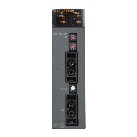
SETTING AND PROCEDURE BEFORE OPERATION MELSEC-Q 4.2 Part Names and Settings 4.2.1 QJ71LP21, QJ71LP21-25, QJ71LP21S-25, QJ71LP21G, QJ71LP21GE, QJ71BR11 (Remote master station) QJ71LP21, QJ71LP21-25, QJ71LP21S-25, QJ71LP21G, QJ71LP21GE LED indications Description Name LED status Normal operation ON (green) Watchdog timer error (hardware failure) Operating as a remote master station ON (green) Not operating as a remote master station... - Page 123 SETTING AND PROCEDURE BEFORE OPERATION MELSEC-Q Name LED status Description ERR. ON (red) • Station number setting error (other than 0 to 64.), mode setting error (set to disabled), operating condition setting error (in parameter), or mounted CPU type error (setting outside the range used, incorrect CPU type) •...
- Page 124 SETTING AND PROCEDURE BEFORE OPERATION MELSEC-Q Mode setting switch This switch sets the operation mode. (Factory default: 0) Set the mode setting switches in the same position on all network modules. QJ71LP21, QJ71LP21G, QJ71LP21GE Setting Description Online (The mode selected by the parameter will be enabled.) Self-loopback test Internal self-loopback test Hardware test...
- Page 125 SETTING AND PROCEDURE BEFORE OPERATION MELSEC-Q (2) QJ71BR11 LED indications Same as the optical loop system. (Refer to Section 4.2.1 (1).) Station number setting switches These switches set the station number of the network module in the network. (Factory default: 1) Setting Description Remote master station setting...
-
Page 126: Qj72Lp25-25, Qj72Lp25G, Qj72Lp25Ge, Qj72Br15
SETTING AND PROCEDURE BEFORE OPERATION MELSEC-Q 4.2.2 QJ72LP25-25, QJ72LP25G, QJ72LP25GE, QJ72BR15 (1) QJ72LP25-25, QJ72LP25G, QJ72LP25GE LED indications Name LED status Description ON (green) Normal operation Watchdog timer error (hardware failure) REM. ON (green) Normal operation Flashing Parameters being written to the flash ROM or in device test mode (green) Being initialized remotely or error (watchdog timer error, fuse blown error, I/O module verify error, or other errors) - Page 127 SETTING AND PROCEDURE BEFORE OPERATION MELSEC-Q Name LED status Description ERR. ON (red) • Station number setting error (other than 1 to 64), mode setting error (set to disabled), or operating condition setting error (in parameter) • A station with the same station number exists in the network. •...
- Page 128 SETTING AND PROCEDURE BEFORE OPERATION MELSEC-Q RS-232 connector A RS-232 cable for a peripheral is connected. Station number setting switches These switches set the station number of the network module in the network. (Factory default: 1) Setting Description Setting error (The ERR. LED turns on (red).) Available setting range (When the QJ72BR15 is used, setting any of 33 1 to 64 to 64 will result in a setting error.
- Page 129 SETTING AND PROCEDURE BEFORE OPERATION MELSEC-Q IN/OUT connectors An optical fiber cable connector is connected. (Refer to Section 4.8.1.) Name IN: Reverse loop sending IN: Forward loop receiving OUT: Forward loop sending OUT: Reverse loop receiving RESET switch This switch resets the modules on the remote I/O station. Press the switch for one second or longer to reset.
- Page 130 SETTING AND PROCEDURE BEFORE OPERATION MELSEC-Q (2) QJ72BR15 Indicator LEDs Same as the optical loop system. (Refer to Section 4.2.2 (1).) RS-232 connector Same as the optical loop system. (Refer to Section 4.2.2 (1).) Station number setting switch Same as the optical loop system. (Refer to Section 4.2.2 (1).) Mode setting switch This switch sets the operation mode.
-
Page 131: Installing And Uninstalling The Module
SETTING AND PROCEDURE BEFORE OPERATION MELSEC-Q 4.3 Installing and Uninstalling the Module (1) Installing the module Base unit Fully insert the module fixing latch into the module fixing hole in the base unit (exercise care not to allow the module fixing latch to separate from Base unit Module fixing... - Page 132 SETTING AND PROCEDURE BEFORE OPERATION MELSEC-Q [Module handling precautions] • Since the module case is made of resin, do not drop it or subject it to strong impacts. • The module can be easily fixed onto the base unit using the hook at the top of the module.
-
Page 133: Stopping The Cpu (Unintentional Output Prevention)
SETTING AND PROCEDURE BEFORE OPERATION MELSEC-Q 4.4 Stopping the CPU (Unintentional Output Prevention) Set the CPU module's RUN/STOP switch to the STOP side. STOP 4.5 Checking the Input Power Supply Voltage Check that the supply power voltage to the power supply module is within the specifications. -
Page 134: Unit Tests Of The Network Module (Offline Test)
SETTING AND PROCEDURE BEFORE OPERATION MELSEC-Q 4.7 Unit Tests of the Network Module (Offline Test) The network module and the connected cable shall be tested before executing the data link operation. Select the test item with the mode setting switch on the front of the network module. -
Page 135: Self-Loopback Test
SETTING AND PROCEDURE BEFORE OPERATION MELSEC-Q 4.7.1 Self-loopback test This test checks the internal circuits including the send/receive circuits of the network module together with the connected cable. POINT Always connect a cable or terminating resistors when performing the self-loopback test. - Page 136 SETTING AND PROCEDURE BEFORE OPERATION MELSEC-Q REMARKS Check the test condition and error details with the following link special register areas. • Baton pass status (host) (SW0047) → 1FH: Offline test • Cause of baton pass interruption (SW0048) → 2H: Offline test •...
-
Page 137: Internal Self-Loopback Test
SETTING AND PROCEDURE BEFORE OPERATION MELSEC-Q 4.7.2 Internal self-loopback test This test checks the internal circuits including the send/receive circuits of the network module. Do not connect an optical fiber cable for the QJ71LP21/QJ72LP25 network module (for the optical loop system). Prevent ambient light from entering the connector. - Page 138 SETTING AND PROCEDURE BEFORE OPERATION MELSEC-Q REMARKS Check the test condition and error details with the following link special register areas. • Baton pass status (host) (SW0047) → 1FH: Offline test • Cause of baton pass interruption (SW0048) → 2H: Offline test •...
-
Page 139: Hardware Test
SETTING AND PROCEDURE BEFORE OPERATION MELSEC-Q 4.7.3 Hardware test This test checks the internal components of the network module. For the QJ71LP21/QJ72LP25 network module (for the optical loop system), connect the IN connector and OUT connector with an optical fiber cable. Do not connect cables or terminating resistors if the QJ71BR11/ QJ72BR15 network module (for the coaxial bus system) is used. - Page 140 SETTING AND PROCEDURE BEFORE OPERATION MELSEC-Q REMARKS Check the test condition and error details with the following link special register areas. • Baton pass status (host) (SW0047) → 1FH: Offline test • Cause of baton pass interruption (SW0048) → 2H: Offline test •...
-
Page 141: Cable Connections
Maintain the bending radius of the optical fiber cable within the allowable range using a tool for securing the optical fiber cable bending radius. This tool may be purchased from Mitsubishi Electric System Service, Inc, or your nearest dealer. Please inquire for more information. - Page 142 SETTING AND PROCEDURE BEFORE OPERATION MELSEC-Q (2) Cable connection How to connect the cable Note that there is no need to connect the cables in the order of station numbers. Set the station number of the remote master station to 0. a - 1) QJ71LP21-25 - QJ72LP25-25, QJ71LP21G - QJ72LP25G Remote master station Remote I/O station...
-
Page 143: Coaxial Bus System
SETTING AND PROCEDURE BEFORE OPERATION MELSEC-Q Removing the optical fiber cable The following are how to remove the optical fiber cable: Removal Plug Turn OFF the power. Press the fixed sections of the plug in Cover the directions of the arrows and pull out the plug. - Page 144 SETTING AND PROCEDURE BEFORE OPERATION MELSEC-Q Cable installation precautions Install the coaxial cables at least 100 mm away from other power cables and control cables. Consider to use double shield coaxial cables in locations where there is excessive noise. To configure a multiplexed remote I/O network for redundant system, use a double shield coaxial cable.
- Page 145 SETTING AND PROCEDURE BEFORE OPERATION MELSEC-Q (2) Cable connection Connection method Connect the coaxial cable as shown below. Always install a terminating resistor (sold separately: A6RCON-R75) to the stations connected at both ends. The F-type connector (A6RCON-F) comes with the module. Without a repeater module Remote I/O station Remote I/O station...
- Page 146 SETTING AND PROCEDURE BEFORE OPERATION MELSEC-Q With a repeater module (branch connection) Remote I/O station Remote I/O station Remote master station Station No. 0 Station No. 1 Station No. 2 QJ71BR11 QJ72BR15 QJ72BR15 F-type connector F-type connector F-type connector A6RCON-F A6RCON-F A6RCON-F T-type connector...
- Page 147 SETTING AND PROCEDURE BEFORE OPERATION MELSEC-Q Installing the coaxial cable The following are how to install the coaxial cable: Network module Installation Jack Turn OFF the power. Plug Projection Insert the plug by aligning the groove of Groove the plug with the projection of the jack. Rotate the plug in the direction of the arrow (clockwise) securely to the position shown in the second figure from above.
-
Page 148: Offline Tests From Gx Developer
SETTING AND PROCEDURE BEFORE OPERATION MELSEC-Q 4.9 Offline Tests from GX Developer The offline tests check the cable connection status using the network parameters of GX Developer. 4.9.1 Forward loop/reverse loop test (Remote master station only) The forward loop/reverse loop test checks the hardware of the network modules and cables after all stations are connected with optical fiber cables. - Page 149 SETTING AND PROCEDURE BEFORE OPERATION MELSEC-Q Setting the mode when performing the forward loop/reverse loop test on the redundant system When conducting the forward loop/reverse loop test on the redundant system, set the operation mode of the redundant CPU to the backup mode in advance.
- Page 150 SETTING AND PROCEDURE BEFORE OPERATION MELSEC-Q (2) Starting the test High Performance model QCPU, Process CPU, and Redundant CPU Set the RUN/STOP switch of the CPU module to the STOP position. When resetting the CPU module, use the RESET/L.CLR switch. Center RESET Center...
- Page 151 SETTING AND PROCEDURE BEFORE OPERATION MELSEC-Q (3) Checking the test result The T.PASS LED of the network module flashes at approximately 0.5 s intervals. When the T.PASS LED flashes 20 times (approx. 10s) or more and if the ERR.LED does not flash, this condition indicates normal completion. When the test has failed, the ERR.
-
Page 152: Network Diagnostics From Gx Developer (Online Tests)
SETTING AND PROCEDURE BEFORE OPERATION MELSEC-Q 4.10 Network Diagnostics from GX Developer (Online Tests) With the network diagnostic function of GX Developer, the line status can easily be checked and diagnosed. Conduct network diagnostics by connecting GX Developer with a remote master station. -
Page 153: Loop Test (Optical Loop System Only)
SETTING AND PROCEDURE BEFORE OPERATION MELSEC-Q 4.10.1 Loop test (optical loop system only) This test checks the line status (forward loop or reverse loop) after all stations are connected to the optical loop system. GX Developer Remote Reserved station master station Loopback Station Station... -
Page 154: Setup Confirmation Test
SETTING AND PROCEDURE BEFORE OPERATION MELSEC-Q 4.10.2 Setup confirmation test This test checks the switch setting of a network module. The following items can be checked. Control station overlap status (This check is not performed on remote I/O network.) Station number duplication status Network No. -
Page 155: Station Order Check Test (Optical Loop System Only)
SETTING AND PROCEDURE BEFORE OPERATION MELSEC-Q 4.10.3 Station order check test (optical loop system only) This test checks the order of connected stations in the optical loop system. The following table lists the correspondence between the loop status and the order of stations that can be checked in the test. -
Page 156: Communication Test
SETTING AND PROCEDURE BEFORE OPERATION MELSEC-Q 4.10.4 Communication test This test checks whether communications is normally performed between the host station and a communication-target station (specified with the network number and station number). If the communication-target station is in another network, the relay network number and station number are displayed and the routing parameter settings can be checked. - Page 157 SETTING AND PROCEDURE BEFORE OPERATION MELSEC-Q MEMO 4 - 37 4 - 37...
-
Page 158: Parameter Settings
PARAMETER SETTINGS MELSEC-Q 5 PARAMETER SETTINGS To operate a remote I/O network, parameters must be set up for the CPU module on the remote master station and remote I/O modules on remote I/O stations accordingly. Settings ranging from MELSECNET/H type selection to application function details can be configured with parameters. - Page 159 PARAMETER SETTINGS MELSEC-Q (2) Parameter settings for a remote I/O station Set the following functions as necessary. Required PLC Parameters · · · · Section 5.2.1 (1) PLC system (2) PLC RAS (3) Operational settings (4) I/O assignment Not required Intelligent function module parameter settings Set the following functions as necessary.
- Page 160 PARAMETER SETTINGS MELSEC-Q Table 5.1 Remote master station network parameter setting items Network station type Reference Remote master station Parameter setting item section — Settings with the network module Section 4.3 Station number (STATION No.) Section 4.3.1 Mode (MODE) Section 4.3.2 —...
- Page 161 PARAMETER SETTINGS MELSEC-Q Table 5.2 Remote I/O station PLC parameter setting items Network station type Reference Remote I/O station Parameter setting item section — PLC system Points occupied by empty slot Section 5.2.1 Module synchronization — PLC RAS Operating mode when there is an error Section 5.2.1 Error check —...
-
Page 162: Remote Master Station Parameter Setting
PARAMETER SETTINGS MELSEC-Q 5.1 Remote Master Station Parameter Setting The remote master station sets the network parameters to the CPU module. 5.1.1 Setting the number of modules (Network type) Set the network type and the station type for each module. No. -
Page 163: Network Settings
PARAMETER SETTINGS MELSEC-Q 5.1.2 Network settings These parameters are used to configure the MELSECNET/H network. Set the starting I/O No., network No., total number of (slave) stations, group No. and mode for each of the module model names set in the number of modules settings. (1) Starting I/O No. -
Page 164: Group No. (Available For Multiplexed Remote Master/Sub-Master Station Only)
PARAMETER SETTINGS MELSEC-Q (4) Group No. (available for multiplexed remote master/sub-master station only) Set the group No. to send data simultaneously to other stations in transient transmission. (a) Valid setting range : No group specification (default) 1 to 32 : Group No. (5) Mode Set the operation mode of the network module. -
Page 165: Parameter Setting Example
PARAMETER SETTINGS MELSEC-Q (6) Parameter setting example The following is an example for system parameter settings including remote master station (remote I/O network) and controlling station (PLC to PLC network). (System configuration) Remote master station Control station QCPU QJ71 QJ71 LP21 BR11 Valid module during other... -
Page 166: Common Parameter
PARAMETER SETTINGS MELSEC-Q 5.1.3 Common parameter The common parameters set the LB, LW, LX and LY cyclic transmission ranges that allows sending and receiving between a remote master station and remote I/O stations in a network. Common parameters only need to be set for the remote master station. (1) LX/LY setting I/O signals (X, Y) of each remote I/O station are transferred to the CPU module via link devices (LX, LY) of the remote master station for control in the CPU... - Page 167 PARAMETER SETTINGS MELSEC-Q REMARKS The link device (LX, LY) data of the remote master station are refreshed to the internal user devices (e.g. X, Y) of the CPU module to be used in sequence programs. To refresh these data to the CPU module's input (X) or output (Y) area, assign them to the area after the actual I/O.
- Page 168 PARAMETER SETTINGS MELSEC-Q POINT (1) Set the setting for the remote master station side to the input/output number of the remote I/O station module that is mounted. Remote master station Remote I/O station Actual I/O 1FFF 1FFF If there is an error in the mounting condition, malfunctioning will occur. Remote master station Remote I/O station Actual I/O...
-
Page 169: Lb/Lw Setting
PARAMETER SETTINGS MELSEC-Q (2) LB/LW setting The LB/LW data on each remote I/O station are transferred to the CPU module via LB/LW of the remote master station for control in the CPU module. In the LB/LW setting, set the area ranges for sending data from the remote master station to each remote I/O station and for receiving data from each remote I/O station to the remote master station. -
Page 170: Reserved Station Specification
PARAMETER SETTINGS MELSEC-Q POINT (1) Set so that the M station R station and M station R station do not overlap. Good example Bad example M station R station M station R station M station M station R station R station (2) When the MELSECNET/H remote I/O network uses the link dedicated instructions (REMFR, REMTO, READ, WRITE), there is no need for LB/LW for handshake that was required for MELSECNET/10. - Page 171 PARAMETER SETTINGS MELSEC-Q POINT In the case of the multiplexed remote I/O network for redundant system, set the link devices in the tracking settings in the redundant parameters to update the link devices between the multiplexed remote master station and multiplexed remote sub-master station.
-
Page 172: Supplementary Settings
PARAMETER SETTINGS MELSEC-Q 5.1.4 Supplementary settings The supplemental settings are included in common parameter settings to provide more precise usage. Keep the default settings for normal use. Common parameters supplemental are only for remote master stations. [Setting items] Constant scan The constant link scan function is used to maintain the link scan time constant. - Page 173 PARAMETER SETTINGS MELSEC-Q Maximum No. of returns to system stations in 1 scan (refer to Section 3.2.2) Set the number of faulty stations that can return to the network in one link scan. : 1 to 64 stations • Valid number of stations : 2 stations •...
- Page 174 PARAMETER SETTINGS MELSEC-Q Transient setting Set the execution conditions for the transient transmission. "Maximum No. of transients in 1 scan" Set the number of transients (total for one entire network) that a single network can execute in one link scan. •...
- Page 175 PARAMETER SETTINGS MELSEC-Q POINT (1) Transient request processing may be prolonged in a system where transient requests are made frequently (e.g. a system including a remote I/O station to which a GOT is mounted). In such a case, make the following setting. (a) Parameter setting for the remote master station Increase the value set in No.
-
Page 176: Refresh Parameters
PARAMETER SETTINGS MELSEC-Q 5.1.5 Refresh parameters The refresh parameters are used to transfer the link device data (LB, LW, LX, LY) of the network module to the devices (X, Y, M, L, T, B, C, ST, D, W, R, ZR) of the CPU module for operation of the sequence programs. - Page 177 PARAMETER SETTINGS MELSEC-Q (Refresh parameter setting screen) POINT The assignment image diagram can display schematic images of CC-Link IE Controller Network, CC-Link IE Field Network and MELSECNET/H (network modules on controller networks, PLC to PLC networks, and remote I/O networks). Avoid any duplicate settings of the programmable-controller-side devices that are used for the following.
- Page 178 PARAMETER SETTINGS MELSEC-Q End button Click this button to return to the network setting screen after completing the data settings. REMARKS [Random cyclic] is for future use. An error will not occur even if it is selected, but no processing will be performed. 5 - 21 5 - 21...
- Page 179 PARAMETER SETTINGS MELSEC-Q POINT Either of the following settings must be made to use the entire device range (16K points) of LB/LW. Change the number of B/W device points. (Refer to the following example.) Make the refresh parameter settings so that B/W and other devices will be assigned as the refresh destination devices of LB/LW.
- Page 180 PARAMETER SETTINGS MELSEC-Q (1) Concept of the link refreshing (a) Link refresh ranges The ranges that are set in Refresh parameters and that are set with common parameters are refreshed. (b) Devices for which link refreshing can be executed 64 transfer settings (LX, LY, LB, LW), one SB transfer setting and one SW transfer setting can be performed for each master module.
- Page 181 PARAMETER SETTINGS MELSEC-Q (2) How to set the refresh parameters (a) Automatic setting with the Default button When B/W points set in [Device] under [PLC parameter] are 8K points or more (6K points or more when three modules are mounted) Link devices are assigned as shown below.
- Page 182 PARAMETER SETTINGS MELSEC-Q When B/W points set in [Device] under [PLC parameter] are less than 8K points (less than 6K points when three modules are mounted) Link devices equivalent to the B/W points set in [Device] are assigned, up to the following points for each module. No.
- Page 183 PARAMETER SETTINGS MELSEC-Q (b) Manual setting by direct input Select "Assignment method". Select "Points/Start" when entering link device points and start addresses. Select "Start/End" when entering start and end addresses of link devices. Configure the settings for the link side and CPU side devices. Example: When "Start/End"...
- Page 184 PARAMETER SETTINGS MELSEC-Q (3) When no refresh parameters are set (High Performance model QCPU, Process CPU, and Redundant CPU) Link devices are assigned as shown below. Installation location Module 1 Module 2 Module 3 Module 4 Number of installation LB/LW 8192 points 1 Module...
- Page 185 PARAMETER SETTINGS MELSEC-Q POINT When B/W points less than the following are set in [Device] under [PLC parameter], set refresh parameters accordingly. Or, increase the B/W points to the following value or more in [Device]. Device points in [Device] No. of modules 8K points 8K points 8K points...
- Page 186 PARAMETER SETTINGS MELSEC-Q (4) Setting example The following shows an example of the refresh parameters settings: [System configuration] QCPU QJ71 QJ71 LP21 BR11 Network No.2 Network No.1 [Parameter assignments] CPU module Master module (1M Master module (2M 1000 to 107F 1000 to 107F 1100 to 117F 1100 to 117F...
- Page 187 PARAMETER SETTINGS MELSEC-Q [Setting screen] The following shows the settings of the refresh parameters for each module that are displayed on the screen. Settings of module 1 (1M Settings of module 2 (2M ) (transfer SB, transfer SW, transfers 1 and 2) 5 - 30 5 - 30...
-
Page 188: Valid Module During Other Station Access
PARAMETER SETTINGS MELSEC-Q 5.1.6 Valid module during other station access This parameter is used to specify any of the following modules to be relayed when a data communication request for which the network No. of the access target programmable controller station cannot be specified from the host (access from the serial communication module (A compatible 1C frame), Ethernet module (A compatible 1E frame), etc. -
Page 189: Redundant Settings
PARAMETER SETTINGS MELSEC-Q 5.1.7 Redundant settings For the multiplexed remote master station for redundant system, it is necessary to set the same mode as the mode applied to the multiplexed remote master station (system A) to the multiplexed remote sub-master station (system B). Set the mode of system B in the redundant settings. -
Page 190: Remote I/O Station Parameter Settings
PARAMETER SETTINGS MELSEC-Q 5.2 Remote I/O Station Parameter Settings For remote I/O stations, set up the PLC parameters, network parameters, and remote password on the remote I/O module as needed. POINT After writing the parameters to the remote I/O module, reset it to enable the parameters that have been set. - Page 191 PARAMETER SETTINGS MELSEC-Q 1: The operation mode of a remote I/O station under the error status can be set differently from the parameters of the remote master station (CPU module). When an error (fuse blowout or I/O verification error) occurs on the remote master station (CPU module) and remote I/O station, the data link and output of the remote I/O station are determined based on the combination of the parameter settings of remote I/O stations and remote master station (CPU...
- Page 192 PARAMETER SETTINGS MELSEC-Q Operational settings Remote I/O switch setting For future expansion. Cannot be set at present time. Assignment method Select the assignment method for sending parameters between devices: "Points/Start" or "Start/End". • Assign the bit device (B, M) points in increments of 16 and the start/end addresses with the number in multiples of 16.
- Page 193 PARAMETER SETTINGS MELSEC-Q POINT When the intelligent function module buffer memory is located in several different areas, the forwarding parameter between devices are convenient when combining them for access. Intelligent function Master module CPU module Remote I/O module module Buffer Buffer Link register W memory...
- Page 194 PARAMETER SETTINGS MELSEC-Q (2) Network parameters The remote I/O module can set network parameters in the same way as the CPU module. Major Items Description Ethernet settings Sets the Ethernet network parameters. CC-Link settings Sets the CC-Link settings network parameters. For details on Ethernet settings, refer to "Q Corresponding Ethernet Interface Module User's Manual (Basic) (SH-080009).
- Page 195 PARAMETER SETTINGS MELSEC-Q (4) Intelligent function module parameters The parameters of a connected intelligent function module and the auto refresh setting can be set in remote I/O modules. Major Items Description Initial setting Set the parameters of an intelligent function module. Up to 512 items can be set for the initial setting.
-
Page 196: Programming
PROGRAMMING MELSEC-Q 6 PROGRAMMING When diverting the program example introduced in this chapter to the actual system, fully check that there are no problems in the controllability of the system. 6.1 Programming Precautions This section explains the precautions in creating programs using data on the network. 6.1.1 Interlock related signals A list of the interlock signal devices used in the sequence programs is provided below. - Page 197 PROGRAMMING MELSEC-Q List of Interlock Devices Use permitted/prohibited Remote Control Normal Remote I/O Name Description master station station station station Optical Coaxial Optical Coaxial Optical Coaxial Optical Coaxial Indicates the communication status between the network module SB0020 and the CPU module. Module status (32) Off: Normal...
- Page 198 PROGRAMMING MELSEC-Q Use permitted/prohibited Remote Control Normal Remote I/O Name Description master station station station station Optical Coaxial Optical Coaxial Optical Coaxial Optical Coaxial Stores the baton pass status of each station (Including the host). <Online> 0: Normal (including the stations with the maximum station number and smaller numbers as well as reserved stations) 1: Abnormal SW0070...
-
Page 199: Program Example
PROGRAMMING MELSEC-Q 6.1.2 Program example Interlocks should be applied to the programs according to the link status of the host and other stations. The following example shows an interlock in the communication program that uses the link status of the host (SB0047, SB0049) and the link status of station number 2 (bit 1 of SW0070 and bit 1 of SW0074). - Page 200 PROGRAMMING MELSEC-Q If the initial settings for the buffer memory of the intelligent function module on a remote I/O station are set by a link dedicated instruction (REMTO instruction), write the program so that when only that remote I/O module is reset (by turning the remote I/O module power supply off or by using the remote I/O module reset switch), the remote master station will detect that condition and will once again execute the initial settings in the intelligent function module.
- Page 201 PROGRAMMING MELSEC-Q The following cases may occur when performing the initial settings to the intelligent function module. Analog-digital conversion module Q64AD A/D conversion permit/prohibit setting. Digital-analog conversion module Q62DA D/A conversion permit/prohibit. The operating status of the remote I/O station can be confirmed by the special register for the links for each station baton pass status (SW0070 to SW0073).
-
Page 202: Cyclic Transmission
PROGRAMMING MELSEC-Q 6.2 Cyclic Transmission Depending on the timing of the link refresh, 32-bit (2-word) type link data may be broken up into new and old data in units of 16 bits (one word). • Current values of analog-digital converter module •... -
Page 203: Block Data Assurance Per Station Of Cyclic Data
PROGRAMMING MELSEC-Q 6.2.2 Block data assurance per station of cyclic data Since link refresh is performed by handshaking between the CPU and network modules, cyclic data integrity is assured in units of stations. The Block data assurance per station of cyclic data is a function that prevents link data consisting of two words (32 bits), such as a current value of a positioning module, from being divided into new and old data in units of one word (16 bits). -
Page 204: Communications With I/O Modules
PROGRAMMING MELSEC-Q 6.3 Communications with I/O Modules This section describes the setting and programming that are required for a CPU to communicate with I/O modules on a remote I/O station by cyclic transmission. (1) System configuration example Remote I/O station (station No. 1) Remote master station QJ72 QX40 QY40P... -
Page 205: Communications With Intelligent Function Modules
PROGRAMMING MELSEC-Q 6.4 Communications with Intelligent Function Modules This section describes the setting and programming that are required for a CPU module to communicate with intelligent function modules on a remote I/O station by cyclic transmission. (1) System configuration example Remote I/O station (station No. -
Page 206: Program Example When Using Gx Configurator
PROGRAMMING MELSEC-Q 6.4.1 Program example when using GX Configurator (1) Setting for the CPU module on the remote master station Set network parameters in GX Developer. (a) Setting network parameters • Network type : MNET/H (Remote master) • Starting I/O No. : 0000 •... - Page 207 PROGRAMMING MELSEC-Q (2) Setting for the remote I/O module In GX Developer, set the intelligent function module switches. (Refer to Section 6.4 (1).) Also, set intelligent function module parameters in GX Configurator. Configure the following settings. • Start I/O No. : 20 •...
- Page 208 PROGRAMMING MELSEC-Q (b) Auto refresh setting CH1 Digital output value ········ "W11" CH2 Digital output value ········ "W12" CH3 Digital output value ········ "W13" Error code ·························· "W14" 1: Note that the number of intelligent function module parameters that may be set for automatic refresh setting is limited. The number of parameters that may be set for automatic refresh setting is as follows.
- Page 209 PROGRAMMING MELSEC-Q (3) Program example * Digital output value read Read the CH1 digital output value Read the CH2 digital output value Read the CH3 digital output value * Error code display and reset Output the error code in BCD Turn ON the error clear request (YF) Turn OFF the error clear...
-
Page 210: Program Example When Not Using Gx Configurator
PROGRAMMING MELSEC-Q 6.4.2 Program example when not using GX Configurator POINT Execution of the REMFR/REMTO instruction needs several scans. Therefore, the execution result of the REMFR/REMTO instruction cannot be synchronized with operations of the I/O signals. When reading a digital output value on a Q64AD after changing the operating condition during operation, be sure to read the A/D conversion completed flag (buffer memory address 10) at the same time. - Page 211 PROGRAMMING MELSEC-Q (3) Program example * Remote I/O station operating status checking Master station baton pass status checking Master station data link status checking Remote I/O station baton pass status checking Remote I/O station data link status checking Remote I/O parameter communication status checking Master module status checking...
- Page 212 PROGRAMMING MELSEC-Q 6 - 17 6 - 17...
-
Page 213: Link Dedicated Instruction List
PROGRAMMING MELSEC-Q 6.5 Link Dedicated Instruction List The following table outlines the instructions that can be used for the MELSECNET/H. For details on the format and program examples of each instruction, refer to the applicable section listed in the Reference section column. List of link dedicated instructions : Can be used : Cannot be used... - Page 214 PROGRAMMING MELSEC-Q Target station Execution station Multiplexed Multiplexed Reference Redundant Name Description Instruction Process remote remote section master sub-master station station SEND: Writes data to the target station (network module) of the target network No. RECV: Reads the data sent by SEND to the CPU device. Data SEND send...
- Page 215 PROGRAMMING MELSEC-Q Target station Execution station Multiplexed Multiplexed Reference Redundant Name Description Instruction Process remote remote section master sub-master station station [A-compatible instruction] Reads the CPU device data of the target station of the target network Other Network module Network module station Word device Channel 1...
- Page 216 PROGRAMMING MELSEC-Q Target station Execution station Multiplexed Multiplexed Reference Process Redundant Name Description Instruction remote remote section master sub-master station station Performs "Write clock data" to the CPU module of the other station. Network module Network module Write Channel 1 clock Channel 2 Channel 3...
- Page 217 PROGRAMMING MELSEC-Q REMARKS If the SREAD or SWRITE instruction is erroneously executed to a remote I/O station, the notification device to the target station is ignored and it is processed in the same manner as the READ or WRITE instruction. 6 - 22 6 - 22...
-
Page 218: Using The Link Special Relays (Sb)/ Link Special Registers (Sw)
PROGRAMMING MELSEC-Q 6.6 Using the Link Special Relays (SB)/ Link Special Registers (SW) The data linking information is stored in the link special relays (SB)/link special registers (SW). They can be used by the sequence programs, or used for investigating faulty areas and the causes of errors by monitoring them. - Page 219 PROGRAMMING MELSEC-Q (Cyclic transmission restart) 8) In the following link special register (SW), specify a station for restarting cyclic transmission • Specification of target station Link stop/startup direction content (SW0000) • Specification of station No. Link stop/startup direction content (SW0001 to SW0004) Turn System link startup (SB0002) ON.
- Page 220 PROGRAMMING MELSEC-Q (b) Cyclic transmission stop/restart of the host (Cyclic transmission stop) Turn Link stop (host) (SB0001) ON. When the network module accepts a request, Cyclic transmission stop acknowledgment status (host) (SB004E) is turned ON. When the cyclic transmission stop is completed, Cyclic transmission stop completion status (host) (SB004F) is turned ON.
- Page 221 PROGRAMMING MELSEC-Q (2) Checking data link The data link status is checked through the GX Developer network diagnostics, but it also can be checked with link special relay (SB) and link special register (SW). (Refer to Sections 8.1.1 and 8.1.2.) (a) Check the data link status of other stations Link scan time etc., can be checked in SW005A to SW005B and SW006B to SW006D.
- Page 222 PROGRAMMING MELSEC-Q (b) Checking data link status of the host Link scan time etc., can be checked in SW005A to SW005B and SW006B to SW006D. If an error occurs to data link, either of the following link special relays (SB) will be turned ON. •...
- Page 223 PROGRAMMING MELSEC-Q (3) Checking transient transmission errors Transient transmission errors are checked through the GX Developer network diagnostics, but they also can be checked with link special relays (SB) and link special registers (SW). (Refer to Section 8.1.4) When a transient transmission error occurs, Transient error (SB00EE) is turned ON.
- Page 224 PROGRAMMING MELSEC-Q (4) Checking cables for faults The cable condition can be checked not only in the network diagnostics of GX Developer but also with link special relays (SB) and link special registers (SW). (Refer to Section 8.1.4.) When a communication error occurs due to a cable fault, the error count is stored in any of the link special registers (SW) in the table below.
- Page 225 PROGRAMMING MELSEC-Q (5) Checking the forward/reverse loop in the optical loop system The forward/reverse loop in the optical loop system can be checked not only in the network diagnostics of GX Developer but also with link special relays (SB) and link special registers (SW). (Refer to Sections 8.1.1 and 8.1.2.) (a) Checking the forward/reverse loop of another station When an error occurs on the forward or reverse loop, the following link special relay (SB) is turned ON.
- Page 226 PROGRAMMING MELSEC-Q (b) Checking the forward/reverse loop of the host When an error occurs on the forward or reverse loop, Host loop status (SB0090) turns ON. If loopback occurs, the cause of the loopback is stored in Loop switch data (SW00D0 to SW00DF). The position of the loop switch data storage can be checked with Loop switch data pointer (SW00CF).
- Page 227 PROGRAMMING MELSEC-Q (6) Checking the offline test status The test status is checked through the LEDs on the network module, but it also can be checked with link special relays (SB) and link special registers (SW). (Refer to Section 4.7.) (a) Requesting side When the offline test is instructed, Offline test instruction (SB00AC) is turned ON.
- Page 228 PROGRAMMING MELSEC-Q (7) Checking the online test status The test status is checked through LED of the network module main frame, but it also can be checked with link special relay (SB) and link special register (SW). (Refer to Section 4.10.) (a) Requesting side When the online test is instructed, Online test instruction (SB00A8) is turned ON.
- Page 229 PROGRAMMING MELSEC-Q (8) Checking parameter status The reflection status and setting contents of parameters can be checked with link special relay (SB) and link special register (SW). (a) Checking parameter status of other stations Check the following link special relay (SB) and link special register (SW) with the remote master station.
- Page 230 PROGRAMMING MELSEC-Q (b) Checking the parameter status of the host (including the switch setting on the network module) Upon completion of receiving parameters, Parameter receive status (SB0054) is turned OFF. If any error is found in the parameters, the following link special relays (SB) are turned ON.
- Page 231 PROGRAMMING MELSEC-Q (9) Checking the remote master station's CPU module and remote I/O station statuses (Error detection of remote I/O stations) The status check can be performed not only with the network diagnostics in GX Developer but also with link special relays (SB) and link special registers (SW). (Refer to Sections 8.1.2 and 8.1.3.) (a) Checking the remote I/O station status (Error detection of remote I/O stations)
- Page 232 PROGRAMMING MELSEC-Q (b) Checking the remote master station's CPU module status Whether the CPU module is in the RUN or STOP status can be checked in CPU RUN status of the remote master station (SB0085). (SB0086 for the multiplexed remote sub-master station) When a continuation error occurs with the CPU module, Host CPU status (1) (SB004A) is turned ON.
- Page 233 PROGRAMMING MELSEC-Q (11) Operation status check and operation switching of the multiplexed remote master function The operation of the multiplexed remote master function can be checked or switched with link special relays (SB) and link special registers (SW). (a) Checking the operation status of the multiplexed remote master station If an error occurs in data link, any of the following link special relays (SB) is turned ON.
- Page 234 PROGRAMMING MELSEC-Q (c) Checking device ranges of the multiplexed remote master and sub-master stations When Send LY/Receive LX device numbers of the multiplexed remote master and sub-master stations (SW01C8 to SW01CF) become valid, Send/receive device number valid/invalid status (SB01C8) is turned ON. The send/receive device numbers of the multiplexed remote master and sub-master stations can be checked in SW01C8 to SW01CF.
- Page 235 PROGRAMMING MELSEC-Q (13) Setting a link dedicated instruction and checking the processing result With link special relays (SB) and link special registers (SW), link dedicated instructions can be set and the processing results can be checked. Link dedicated instructions can be set with the following link special registers (SW).
- Page 236 PROGRAMMING MELSEC-Q (14) Checking the communication status between the network module and the CPU module The communication status between the network module and the CPU module can be checked with the link special relay (SB) and the link special register (SW). (a) Checking the error details When an error occurs in the communication between the network module and the CPU module, Module status (SB0020) turns ON.
-
Page 237: Application Functions
APPLICATION FUNCTIONS MELSEC-Q 7 APPLICATION FUNCTIONS When applying the program examples introduced in this chapter to the actual system, make sure to examine the applicability and confirm that it will not cause system control problems. : In the application functions, there are executable functions that can be used by setting the parameters to either the remote master station or remote I/O station. -
Page 238: Transient Transmission Function (Non-Periodical Communication)
APPLICATION FUNCTIONS MELSEC-Q 7.1 Transient Transmission Function (Non-Periodical Communication) The transient transmission function performs data communication only when it is requested between stations. The transient transmission function can be requested with the link dedicated instructions (REMFR, REMTO, READ and WRITE) GX Developer, the intelligent function module, etc. -
Page 239: Link Dedicated Instruction
APPLICATION FUNCTIONS MELSEC-Q 7.1.1 Link dedicated instruction (1) Reading/writing remote I/O station intelligent function module buffer memory (Z(P).REMFR/ Z(P).REMTO) This section describes the REMFR/REMTO instruction format. For a program example using the REMFR/REMTO instruction, refer to Section 6.4.2. The REMFR instruction reads the data from the buffer memory of the intelligent function module mounted to the remote I/O station. - Page 240 APPLICATION FUNCTIONS MELSEC-Q Z(P).REMTO (Network No. designation) Write command Z: Executed when on Z.REMTO "Jn" Write command ZP: Executed when rising ZP.REMTO "Jn" : If the originating station is a Universal model QCPU, " "(double quotation) for the first argument can be omitted. Description of setting Setting range Target network No.
- Page 241 APPLICATION FUNCTIONS MELSEC-Q Instruction execution timing Normal completion (REMFR instruction) REMFR Sequence scan Read command Read completion device (Device 1 scan designated in (D2)) Host CPU Read completion device ((D2) + 1 device) Set data (Devices designated in (n3), (n4),(n5)) Read data storage device (Device W (M...
- Page 242 APPLICATION FUNCTIONS MELSEC-Q (REMTO instruction) REMTO Sequence scan Write command Write completion device (Device designated in (D2)) 1 scan Host CPU Write completion device ((D2) + 1 device) Set data (Devices designated in (n3), (n4), (n5)) Write data storage device (Device W (M designated in (D1)) Master module...
- Page 243 APPLICATION FUNCTIONS MELSEC-Q Abnormal completion (REMFR instruction) REMFR Sequence scan Read command Read completion device (Device designated in (D2)) Host CPU Read completion device ((D2) + 1 device) 1 scan Set data (Devices designated in (n3), (n4), (n5)) Send/receive instruction processing result Error code (SW0031 to SW003F)
- Page 244 APPLICATION FUNCTIONS MELSEC-Q (REMTO instruction) REMTO Sequence scan Write command Write completion device (Device designated in (D2)) Write completion Host CPU device ((D2) + 1 device) 1 scan Set data (Devices designated in (n3), (n4), (n5)) Write data storage device (Device Error code W (M designated in (D1))
-
Page 245: Remote I/O Station System Monitor
APPLICATION FUNCTIONS MELSEC-Q 7.2 Remote I/O Station System Monitor With the remote I/O network, the intelligent function module mounted to a remote I/O station can be monitored on the system monitor of GX Developer. By using this, it is possible to easily diagnose the intelligent function module on the remote I/O station. -
Page 246: Device Test For Remote I/O Station
APPLICATION FUNCTIONS MELSEC-Q 7.3 Device Test for Remote I/O Station The remote I/O network can use operations of GX Developer connected to the remote I/O station to test the input/output devices of the sequence program without affecting the online system. To conduct a test without affecting the system, register the device to be tested in "Forced input output registration/cancellation"... - Page 247 APPLICATION FUNCTIONS MELSEC-Q (2) The remote I/O module stops the X input from the input module At this time, the remote I/O station is performing X/Y communication with the remote master station. The remote master station uses GX Developer which is connected directly to the remote I/O module to perform make an X input from GX Developer to the remote I/O station and perform an X input test.
-
Page 248: Multiplex Transmission Function (Optical Loop System)
APPLICATION FUNCTIONS MELSEC-Q 7.4 Multiplex Transmission Function (Optical Loop System) Master Remote The multiplex transmission function allows high-speed communications using duplex transmission paths (both the forward and reverse loops) in the optical loop system. In order to execute the multiplex transmission function, setting for the "Supplementary settings"... -
Page 249: Return Sequence Station Number Setting Function
APPLICATION FUNCTIONS MELSEC-Q 7.5 Return Sequence Station Number Setting Function Master Remote The remote I/O net can set the number of stations for which stations with communication errors during one link scan can perform return sequence. If the number of stations set is large, a large number of communication stations with errors can perform return sequence. -
Page 250: Interrupt Settings
APPLICATION FUNCTIONS MELSEC-Q 7.7 Interrupt Settings Master Remote The remote master station uses the host interrupt setting parameters to check interrupt conditions at the time data is being received from the remote I/O station. When the interrupt conditions are matched, it issues an interrupt request to CPU module from the master module and starts the interrupt sequence program of the CPU module. -
Page 251: I/O Assignment Function
APPLICATION FUNCTIONS MELSEC-Q 7.8 I/O Assignment Function Master Remote The I/O assignment function is used for the following: 1) Reserving points when changing to a module other than 16-point modules 2) Preventing I/O number change after module replacement 3) Changing I/O numbers to those used in the program 4) Setting input response time (I/O response time) 5) Setting an output mode for a data link error (Error time output mode setting) 6) Setting a remote I/O station operation mode for a hardware error in an intelligent... -
Page 252: Stopping/Restarting The Cyclic Transmission And Stopping Link Refreshing (Network Test)
APPLICATION FUNCTIONS MELSEC-Q 7.9 Stopping/Restarting the Cyclic Transmission and Stopping Link Refreshing (Network Test) The remote I/O network can use the "network test" of GX Developer to stop and restart cyclic data. This function is useful when other station's data should not be received or when the host's data should not be sent at system startup (when debugging), etc. -
Page 253: Multiplexed Remote Master Function (Process Cpu)
APPLICATION FUNCTIONS MELSEC-Q 7.10 Multiplexed Remote Master Function (Process CPU) The multiplex remote master function allows the multiplexed remote sub-master station to take control of the remote I/O stations when the multiplexed remote master station fails. Multiplexed remote Multiplexed remote master station sub-master station Remote I/O station Remote I/O station... - Page 254 APPLICATION FUNCTIONS MELSEC-Q The following describes each item. (1) Continuation of controlling remote I/O stations when multiplexed remote master station fails By mounting the master modules of the multiplexed remote master station and multiplexed remote sub-master station to different programmable controller CPUs, the multiplexed remote sub-master station automatically controls the remote I/O stations if the multiplexed remote master station fails (switching of master operation).
- Page 255 APPLICATION FUNCTIONS MELSEC-Q The intelligent function modules such as serial communication module, Ethernet module which are mounted to the remote I/O stations can access the station that is currently performing master operation in the MELSEC communication protocol. Access Destination Target Station Number to Be Set Multiplexed remote master station (Station No.
- Page 256 APPLICATION FUNCTIONS MELSEC-Q Select the multiplexed remote master station or multiplexed remote sub- master station from "Network type" on the "Module count setting screen" of the GX Developer parameters. • Multiplexed remote master station: • Multiplexed remote sub-master station: Since the multiplexed remote master station needs to recognize the station number of the multiplexed remote sub-master station, set the station number of the multiplexed remote sub-master station on the network range assignment screen of the multiplexed remote master station.
- Page 257 APPLICATION FUNCTIONS MELSEC-Q (2) Selection of operating station status when multiplexed remote master station returns to system It is possible to set the parameter of the multiplexed remote master station to select whether the remote I/O stations will be controlled by the multiplexed remote master station or by the multiplexed remote sub-master station when the multiplexed remote master station returns to system while the remote I/O stations are being controlled by the multiplexed remote sub-master station.
- Page 258 APPLICATION FUNCTIONS MELSEC-Q Return to system as standby station: The multiplexed remote master station returns to the system as the sub- master operating station (standby station). The multiplexed remote sub-master station continues the control of the remote I/O stations. Multiplexed remote Multiplexed remote master station sub-master station...
- Page 259 APPLICATION FUNCTIONS MELSEC-Q Switching of multiplexed remote master station operation When the multiplexed remote master station has returned to system, it can be switched to master operation in the following procedure. The multiplexed remote sub-master confirms that the multiplexed remote master station has returned to the system by checking the link special relay (SB) status.
- Page 260 APPLICATION FUNCTIONS MELSEC-Q The link special relays used to switch multiplexed remote sub-master station operation Number Name Description SB0014 Remote sub-master station switching Forcibly directs the remote sub-master station that is performing command master operation to shift to sub-master operation (invalid for redundant systems).
- Page 261 APPLICATION FUNCTIONS MELSEC-Q (3) Startup of a multiplexed remote sub-master station only By setting the same parameters as the multiplexed remote master station, the multiplexed remote sub-master station continues the control of the remote I/O stations if it is powered on and off while controlling the remote I/O stations.
- Page 262 APPLICATION FUNCTIONS MELSEC-Q (4) Communication among multiplexed remote master station, multiplexed remote sub-master station and remote I/O stations The input (X) data of the remote I/O station and the link relay (B) and link register (W) data sent by the remote I/O station are transferred to both the multiplexed remote master station and multiplexed remote sub-master station.
- Page 263 APPLICATION FUNCTIONS MELSEC-Q • LB/LW data flow between stations Multiplexed remote master station Multiplexed remote sub-master station (master operation) (sub-master operation) LB/LW LB/LW (c) Data transfer (c) Data transfer 1FFF 1FFF LB/LW 1FFF Remote I/O station Multiplexed remote master station fails Multiplexed remote sub-master station Multiplexed remote master station (master operation)
- Page 264 APPLICATION FUNCTIONS MELSEC-Q (6) Program example to transfer data between a multiplexed remote master station and a multiplexed remote sub-master station The following program example assumes that the same program is used on the multiplexed remote master station and multiplexed remote sub-master station to transfer data between the multiplexed remote master station and multiplexed remote sub-master station.
- Page 265 APPLICATION FUNCTIONS MELSEC-Q Link special relay and link special registers used to make the programs identical The following link special relay and link special registers can be used to check the send/receive device ranges of the multiplexed remote master station and multiplexed remote sub-master station. Number Name Description...
- Page 266 APPLICATION FUNCTIONS MELSEC-Q Program example: For multiplexed remote master station Host baton pass status Host data link status Module status SB0075 for multi R sub-master R sub-master cyclic transmission Send LB device No. Receive LB device No. Send LW device No. Receive LW device No.
- Page 267 APPLICATION FUNCTIONS MELSEC-Q R master cyclic trans control Continuation processing program used when multiplexed remote master station fails Station 2 baton path status Station 2 cyclic transmission Program for communication with remote I/O station No. 2 In the timer constant K , set the following value.
-
Page 268: Multiplexed Remote Master Function For The Redundant System (Redundant Cpu)
APPLICATION FUNCTIONS MELSEC-Q 7.11 Multiplexed Remote Master Function for the Redundant System (Redundant CPU) The redundant system uses the multiplexed remote master function to control I/O modules and intelligent function modules. The multiplexed remote master function for the redundant system continues the control of remote I/O stations when the multiplexed remote master station (control system) fails by switching the multiplexed remote master station from the control system to the standby system and switching the multiplexed remote sub-master station (standby... - Page 269 APPLICATION FUNCTIONS MELSEC-Q (2) Station No. settings For the master module mounted on the station (multiplexed remote master station) to which the system A connector of tracking cable is connected, set the station No.0. If the station No. other than 0 is set, the programmable controller CPU will detect the LINK PARA.
-
Page 270: Backup Function Of Master Operation On System Switching Between Control System And Standby System
APPLICATION FUNCTIONS MELSEC-Q 7.11.1 Backup function of master operation on system switching between control system and standby system The redundant system consists of a control system (multiplexed remote master station) and standby system (multiplexed remote sub-master station) of the same system configuration. If a power supply error or CPU error occurs in the control system, the Redundant system switches the standby system to the control system to continue the operation of the redundant system. -
Page 271: Master Operation By The Station That Has Started Up As The Control System
APPLICATION FUNCTIONS MELSEC-Q The output of the remote I/O station is held while master operation is switched from the multiplexed remote master station to the multiplexed remote sub-master station. Multiplexed remote master station Multiplexed remote sub-master station Output is held during system switching. Remote I/O station Remote I/O station Remote I/O station If the multiplexed remote master station returns to the normal status while the multiplexed remote sub-master station controls remote I/O stations, the... -
Page 272: System Switching Request Function Of Control System
APPLICATION FUNCTIONS MELSEC-Q 7.11.3 System switching request function of control system The control system includes the system switching request function, i.e., the master module mounted in the control system CPU issues the system switching request to the control system CPU when it detects the data link error such as link cable disconnection or communication error. - Page 273 APPLICATION FUNCTIONS MELSEC-Q POINT The following must be performed before operating the system • Powering ON/OFF of other stations (including those on the standby system) If the above operation is performed during system operation, a MELSECNET/H module on the control system may detect a communication error and a system- switching request may be issued.
- Page 274 APPLICATION FUNCTIONS MELSEC-Q The master module issues a system switching request when the status of data link is changed from "under data link" to "data link halted" (when the D.LINK LED of the master module turns off). Although the time interval from when the data link is stopped to when the system switching request is issued to the control system CPU is set to two seconds, the interval can be changed using the link special relay (SB) and link special register (SW).
-
Page 275: Access Function By Specifying The Control System Or Standby System
APPLICATION FUNCTIONS MELSEC-Q 7.11.4 Access function by specifying the control system or standby system This function is for making access to the Redundant system by specifying the control system or standby system using GX Developer or other methods. By using this function, access to the control system is enabled even after system switching occurs due to error. -
Page 276: Remote Password
APPLICATION FUNCTIONS MELSEC-Q 7.12 Remote password The remote password function is the function for preventing a remote user from illegally connecting to a remote I/O module and programmable controller CPU. The remote password function can be used by setting a remote password for a remote I/O module. - Page 277 APPLICATION FUNCTIONS MELSEC-Q (2) Unlocking and locking the remote password The remote password is unlocked (connection is allowed) via the modem by the serial communication module or via Ethernet by the Ethernet module. When the remote password is matched, connection to the remote I/O module is allowed.
- Page 278 APPLICATION FUNCTIONS MELSEC-Q (4) Setting procedure of remote password "GX Developer" "Remote pass" "Remote password settings" screen "Remote password detail settings" screen (a) Setting screen (b) Setting items Item Setting Setting range/option Password settings Enter a remote password 4 characters, ASCII code Model name Select a model QJ71E71/QJ71C24/QJ71CMO...
- Page 279 APPLICATION FUNCTIONS MELSEC-Q (5) Error codes detected by remote I/O module Error code Error message LED status Description Measures 3400 REMOTE ERR. LED: The head I/O number of the target Change the head I/O number of the PASS. ERR. module in the remote password file is target module to within the 0 to 0FF0 set to other than 0...
- Page 280 APPLICATION FUNCTIONS MELSEC-Q MEMO 7 - 44 7 - 44...
-
Page 281: Troubleshooting
TROUBLESHOOTING MELSEC-Q 8 TROUBLESHOOTING In order to ensure high system reliability, it is important to take precautions before the system is operated and to quickly and effectively correct problems if they do occur. This is why it is important to perform off-line testing of the network and checking of the cables when first starting the system. -
Page 282: Network Diagnostics (Network Monitor)
TROUBLESHOOTING MELSEC-Q 8.1 Network Diagnostics (Network Monitor) The status of the remote I/O network can be checked using the network diagnostic function of GX Developer. When an error occurs, the faulty station can be identified using the host station information, another station information, and error history monitor functions of the network. - Page 283 TROUBLESHOOTING MELSEC-Q From previous page [Status of self station] • Parameter setting • Reserved station setting • Transmission mode • Duplex transmission setting • Duplex transmission status Error history monitor [Network information] • Network Type • Module No. • Network No. •...
- Page 284 TROUBLESHOOTING MELSEC-Q POINT (1) The target of the network diagnostics is the host's network designated as the connection destination. (2) If the connection target is specified as another station or the redundant CPU is specified as a control system, standby system, system A, or system B, the network monitor can check only the information of the host and other stations.
-
Page 285: Host Information
TROUBLESHOOTING MELSEC-Q 8.1.1 Host information The information of the entire network and the status of the host station can be checked. [Network info.] Network type (SB0040, SB0044, SB0057, SW0046) The network used and the type of the host station are displayed. •... - Page 286 TROUBLESHOOTING MELSEC-Q [Link information] Mode (SW0043) The operation mode of the host station is displayed. • Online • Offline • Forward loop test • Reverse loop test • Station-to-station test (Station that executes tests) • Station-to-station test (Station to be tested) F loop status (SB0091), Loopback station (SB0099) The status on the forward loop side is displayed.
-
Page 287: Other Station Information
TROUBLESHOOTING MELSEC-Q 8.1.2 Other station information The status of communications, data link, parameters, CPU modules, and loops of other stations (including reserved stations) can be checked. The buttons 3) and 7) can be clicked only when the diagnostics is executed from the remote master station. - Page 288 TROUBLESHOOTING MELSEC-Q Data-Link status of each station (SW0074 to SW0077) The cyclic transmission status is displayed. • Light blue : Normal station or reserved station • Red : Error station (data link not being performed) Parameter status of each station The parameter communication status of each station is displayed (SW0078 to SW007B).
-
Page 289: Network Monitor Details
TROUBLESHOOTING MELSEC-Q 8.1.3 Network monitor details The remote master station information, data link information, and parameter status of the host station can be checked. Displayed as shown below when diagnosis is executed from the remote I/O station. [Network info.] The information same as "Host information" in Section 8.1.1 is displayed. [Remote Master Station Information] Assign Remote Master Station (SW0057) The station number (0) of the remote master station is displayed. - Page 290 TROUBLESHOOTING MELSEC-Q [Data Link Information] Total Number of Linked Stations The number of stations (the total number of link stations set in network parameter for the remote master station + 1 (remote master station)) is displayed. Station of Maximum Normal Transmission (SW005A) The greatest station number of the station where the baton pass (transient transmission) is normally performed is displayed.
- Page 291 TROUBLESHOOTING MELSEC-Q 10) Reason for Transmission Stop (SW0049) The cause of the data link (cyclic transmission) failure of the host station is displayed. Item Description Normal Communications being executed normally Cyclic transmission to all stations is stopped There is a stop instruction (All) from the host or other stations.
-
Page 292: Error History Monitor
TROUBLESHOOTING MELSEC-Q 8.1.4 Error history monitor The history of forward/reverse loop errors, communication errors, and transient transmission errors can be checked. The details of the error history can be displayed and the error history can be cleared. (1) Error history monitor [Network info.] The information same as "Host information"... -
Page 293: Troubleshooting
TROUBLESHOOTING MELSEC-Q UNDER (SW00B8, SW00C0) The number of UNDER errors is displayed. <Error Cause> Such as power-ON/OFF of the adjacent station and a cable error <Corrective Action> Refer to the following POINT. CRC (SW00B9, SW00C1) The number of CRC errors is displayed. <Error Cause>... - Page 294 TROUBLESHOOTING MELSEC-Q (2) Error history detail monitoring The cause of loop switching and history of the transient transmission error are displayed. [Loop switching] Station No. (SW00E0 to 00E7) The station number which requested loop switching or loopback is displayed. (The station is not always the adjacent one.) Factor (SW00D0 to 00DF) The factor for the loop switching or loopback is displayed.
- Page 295 TROUBLESHOOTING MELSEC-Q 8.2 Troubleshooting Check the programmable controller CPU for an error before starting the troubleshooting of the network module and network. If the RUN LED of the programmable controller CPU is off/flickering or the ERR. LED is on, identify the error that has occurred in the programmable controller CPU, and take corrective action.
- Page 296 TROUBLESHOOTING MELSEC-Q For the remote I/O module POINT If the status of the "T. PASS" LED is unstable, refer to the following. <Cause> The line status may be unstable. <Troubleshooting> 1) Check the connector for loose connection and the cable for a break. 2) Check that the cable used conforms to the specifications.
- Page 297 TROUBLESHOOTING MELSEC-Q (2) From monitoring the network status to troubleshooting of a faulty station The following flowchart illustrates the procedure for monitoring the status of the entire network, detecting a faulty station, and then performing troubleshooting for the applicable station. The status of the entire network is monitored with GX Developer.
- Page 298 TROUBLESHOOTING MELSEC-Q 8 - 18 8 - 18...
- Page 299 TROUBLESHOOTING MELSEC-Q Is the send and receive data within the system specifications? Is the send/ receive data according to system specifications? Value 0: The host Value of SW0047 transmitting normally <Corrective action> Value 3: No host send area Normal communication Check the contents of each Value 4: Abnormal parameters detected parameter that has been set...
- Page 300 TROUBLESHOOTING MELSEC-Q <Cause 1> M/S error or SW error is assumed. <Corrective action 1> 1) Check for duplicate station number, remote master station duplication or switch setting error. 2) Take corrective action according to the contents of SW0047 and the error code stored in SW0048.
-
Page 301: Items Checked First
TROUBLESHOOTING MELSEC-Q 8.2.1 Items checked first Check item Checking procedure Monitor the transmission status of each station Check the CPU module status of the faulty station, the status of the network modules, with GX Developer 's network diagnostics. the loop status of each station to search for the location where the error has occurred. Read the error code using GX Developer, and take proper measures against the error. -
Page 302: Items Checked When Data Link Is Disabled By Resetting Or Powering Off A Station
TROUBLESHOOTING MELSEC-Q 8.2.3 Items checked when data link is disabled by resetting or powering off a station Check item Checking procedure Check the wiring status with GX Developer's network diagnostic loop test. (Refer to Section 4.10.1.) Is the cable wired properly? In the case of the coaxial bus system, check the coaxial connector connection on each station and connections between the coaxial cables and coaxial connectors. -
Page 303: Items Checked When Data Link Cannot Be Performed On A Certain Station
TROUBLESHOOTING MELSEC-Q 8.2.5 Items checked when data link cannot be performed on a certain station Check item Checking procedure Perform network monitoring of the network diagnostics of GX Developer, check for any abnormally communicating station and check the loop status. Also, check whether or Monitor the transmission status of each station. -
Page 304: Items Checked When An Communication Data Error Is Detected
TROUBLESHOOTING MELSEC-Q 8.2.6 Items checked when an communication data error is detected (1) Cyclic transmission Check item Checking procedure Stop the CPU modules of both the remote master station and turn the link device of the sending station on and off by GX Developer's test operation to check whether or not data is sent to the receiving station. -
Page 305: Items Checked When Multiplexed Remote I/O Network For Redundant System Does Not Operate Normally
TROUBLESHOOTING MELSEC-Q 8.2.8 Items checked when multiplexed remote I/O network for redundant system does not operate normally (1) Redundant CPU does not perform system switching even when the data link cable is disconnected. Check item Checking procedure Isn't the power supply module of the standby Confirm the status of the external power supply of the standby system. -
Page 306: Checking Incorrect Optical Fiber Cable Connection During Online
TROUBLESHOOTING MELSEC-Q 8.2.10 Checking incorrect optical fiber cable connection during online This section explains the checking procedure for incorrect optical fiber cable connection (IN-IN, OUT-OUT) during online and the link special registers (SW009C to SW009F) used for the check. Unlike the loop test, the checking procedure given in this section allows a check without stopping a data link. - Page 307 TROUBLESHOOTING MELSEC-Q (1) Checking procedure Follow the procedure given below to check for incorrect optical fiber cable connection (IN-IN, OUT-OUT) during online. 8 - 27 8 - 27...
- Page 308 TROUBLESHOOTING MELSEC-Q (2) Example of checking SW009C to SW009F (a) When cables are connected incorrectly at a remote I/O station (Station No.2) 1) Wiring diagram Cables are connected to wrong connectors at Station No. 2 (connected OUT-OUT with Station No. 1 and IN-IN with Station No. 3). Station No.
-
Page 309: Error Codes
TROUBLESHOOTING MELSEC-Q 8.3 Error Codes When a trouble such as data link failure has occurred, the error cause can be identified by using an error code. 8.3.1 How to check error codes To check error codes for all network modules, follow either procedure (1) or (2) described in this section. - Page 310 TROUBLESHOOTING MELSEC-Q For the remote master station, check the error code, error history, description, and corrective action on the "Module's Detailed Information" screen. "Module's Detailed Information" screen for a remote master station Check the codes, history, description, and action of an error of the master module For remote I/O stations, check the present error and its history on the "PLC diagnostics"...
- Page 311 TROUBLESHOOTING MELSEC-Q (2) Checking with GX Works2 The error codes corresponding to the errors that have occurred in network modules can be checked by following either procedure (a) or (b) described below. Checking on the "Module's Detailed Information" screen Error code, error contents, and corrective action are displayed. On GX Works2, select [Diagnostics] [System Monitor], and then click Detailed Information button.
- Page 312 TROUBLESHOOTING MELSEC-Q Checking on the "Error History" screen (remote master station only) On this screen, errors including those that have occurred in other modules are displayed, and the data can be output in a CSV file. The error code and date and time of error occurrence can be checked even after powering off and then on the programmable controller or after resetting the programmable controller CPU.
- Page 313 TROUBLESHOOTING MELSEC-Q Error and Solution, Intelligent Module Information • Error and Solution The error detail and corrective action for the error currently selected under "Error History List" are displayed. • Intelligent Module Information The error description and corrective action for the error, which is currently selected under "Error History List", are displayed.
- Page 314 TROUBLESHOOTING MELSEC-Q (3) Checking error codes with devices To monitor the error code from an Ethernet module and so on using the MELSEC communication protocol, check the link special register below. SW0020: Module status SW0048: Cause of baton pass interruption SW0049: Cause of data link stop SW004B: Host CPU status SW004D: Data linking start status (host)
-
Page 315: Melsecnet/H Error Code List
TROUBLESHOOTING MELSEC-Q 8.3.2 MELSECNET/H error code list Table 8.1 Error code list Error code Description Corrective action (Error detected by the programmable Take measures referring to the QCPU User's Manual (Hardware Design, 4000 to 4FFF controller CPU) Maintenance and Inspection). (Error detected by the serial Take measures referring to the troubleshooting section of the Serial 7000 to 7FFF... - Page 316 TROUBLESHOOTING MELSEC-Q Table 8.1 Error code list (Continued) Error code Description Corrective action Review the status of the corresponding station and the parameter and switch settings (to see if there is a parameter error and the corresponding station is the control station and properly set).
- Page 317 TROUBLESHOOTING MELSEC-Q Table 8.1 Error code list (Continued) Error code Description Corrective action Check for the operation status of the control/sub-control station, faulty cables, incorrect cable wiring, and absence of terminating resistor (in the case of the bus). In addition, check whether the same station number has been set for two F11F Initial status (no baton addressed to host) or more stations or whether two or more control stations or remote master...
- Page 318 TROUBLESHOOTING MELSEC-Q Table 8.1 Error code list (Continued) Error code Description Corrective action Wait until SB0047 (baton pass status) and SB0049 (data link status) are F70B Response wait timeout recovered. The cable is faulty, or the hardware of the network module is faulty. F70C System error If a communication error has occurred, review the cable.
- Page 319 TROUBLESHOOTING MELSEC-Q Table 8.1 Error code list (Continued) Error code Description Corrective action The hardware of the network module is faulty. F7CD System error Please consult your local Mitsubishi representative. Confirm the set values (mode, etc.) in the control data of a dedicated F7E1 Control data error instruction.
- Page 320 TROUBLESHOOTING MELSEC-Q Table 8.1 Error code list (Continued) Error code Description Corrective action Replace the network module of the normal station with the one compatible with the MELSECNET/H Extended mode. Change the network type of the normal station to that of the control station. F820 Link parameter error Create new network parameters and perform Write to PLC.
- Page 321 TROUBLESHOOTING MELSEC-Q Table 8.1 Error code list (Continued) Error code Description Corrective action Check if the following conditions are met: The system is a multiplexed remote I/O network system. Check if "Return as a standby station" is set as the parameter for the master F83B Forced switching impossible error station.
- Page 322 TROUBLESHOOTING MELSEC-Q Table 8.1 Error code list (Continued) Error code Description Corrective action There is no need to take corrective measures because the system retries the Interruption error due to loop switching FD1C operation (do not switch the loop in the middle of the operation). during test If the error frequently occurs, check the line and the wiring status.
- Page 323 TROUBLESHOOTING MELSEC-Q Table 8.1 Error code list (Continued) Error code Description Corrective action Confirm the power supply status (insufficient voltage, instantaneous interruption, overvoltage, etc.) of the target station for transient transmission FE25 System error and the relay station. Alternatively, change the CPU module concerned. Confirm the operation status (WDT error, etc.) of the target station and relay FE26 System error...
-
Page 324: Error Codes Detected On Remote I/O Stations And Equivalent To Cpu Module Error Codes
TROUBLESHOOTING MELSEC-Q 8.3.3 Error codes detected on remote I/O stations and equivalent to CPU module error codes The remote I/O station performs some of the same processes as the CPU module. Accordingly, the remote I/O station detects the same error codes as in the CPU module. - Page 325 TROUBLESHOOTING MELSEC-Q (1) Error code list The following table lists the error codes, error messages, error causes, and corrective actions. Error LED status, code Error contents and cause Corrective action Remote I/O (SD0) operation status [MAIN CPU DOWN] Runaway or failure of the remote I/O module •...
- Page 326 TROUBLESHOOTING MELSEC-Q Error LED status, code Error contents and cause Corrective action Remote I/O (SD0) operation status [SP.UNIT DOWN] • There was no response from the intelligent function module in the initial processing. • The size of the buffer memory of the intelligent If an unsupported module is mounted, REM: Off function module is invalid.
- Page 327 TROUBLESHOOTING MELSEC-Q Error LED status, code Error contents and cause Corrective action Remote I/O (SD0) operation status [SINGLE PS. DOWN] The power supply voltage of either of redundant power supply modules on the redundant base unit dropped. REM: Off Collateral information Check the power supplied to the redundant ERR: On 1510...
- Page 328 TROUBLESHOOTING MELSEC-Q Error LED status, code Error contents and cause Corrective action Remote I/O (SD0) operation status [SP. UNIT LAY ERR.] • In the I/O Assignment tab of the PLC parameter dialog box, "Intelligent" (intelligent function module) is set for the slot where an I/O module is mounted, and vice versa.
- Page 329 TROUBLESHOOTING MELSEC-Q Error LED status, code Error contents and cause Corrective action Remote I/O (SD0) operation status [SP.UNIT LAY ERR.] The start X/Y set in the PLC parameter's I/O assignment settings is overlapped with the one for REM: Off Configure the I/O assignment setting of the another module.
- Page 330 TROUBLESHOOTING MELSEC-Q Error LED status, code Error contents and cause Corrective action Remote I/O (SD0) operation status [PARAMETER ERROR] • Read the individual information of the error • The PLC parameter setting for "Points occupied by using GX Works2 or GX Developer to empty slot"...
- Page 331 TROUBLESHOOTING MELSEC-Q Error LED status, code Error contents and cause Corrective action Remote I/O (SD0) operation status [LINK PARA. ERROR] • Although one or more CC-Link modules were configured in the Network Parameter dialog box, no CC-Link module is mounted in the system. •...
- Page 332 TROUBLESHOOTING MELSEC-Q Error LED status, code Error contents and cause Corrective action Remote I/O (SD0) operation status [SP. PARA. ERROR] The intelligent function module's refresh parameter setting is outside the available range. REM: Off Collateral information ERR: On 3301 • Common Information (SD5 to SD15): File name Check the parameter setting.
-
Page 333: Canceling A Minor Error (Continue Error) On A Remote I/O Station
TROUBLESHOOTING MELSEC-Q 8.4 Canceling a Minor Error (Continue Error) on a Remote I/O Station An error of a remote I/O module can be canceled if it is a type of errors that allows the module operation to continue, as in the case of CPU modules. The following explains errors that can be canceled and how to cancel them. -
Page 334: Canceling A Specific Remote I/O Station Error
TROUBLESHOOTING MELSEC-Q 8.4.1 Canceling a specific remote I/O station error This section explains how to cancel an error of a specific remote I/O station by manipulating the remote master station and the remote I/O station. (1) Procedures for error cancellation Use GX Developer and perform the following steps 1) to 7). -
Page 335: Canceling Errors Of All Remote I/O Stations
TROUBLESHOOTING MELSEC-Q 8.4.2 Canceling errors of all remote I/O stations This section explains how to manipulate the remote master station to cancel errors of all remote I/O stations. POINT (1) For canceling errors of all remote I/O stations, use a master module and remote I/O modules whose serial No. - Page 336 TROUBLESHOOTING MELSEC-Q (2) Precautions for error cancellation SB000F after error cancellation Always turn OFF SB000F after canceling an error. Even if a minor error (continue error) occurs on a remote I/O station while SB000F is ON, the error will not be detected. Status after error cancellation When the error is cancelled, the related special relay, special register and LEDs return to the status before the error occurrence.
- Page 337 TROUBLESHOOTING MELSEC-Q (3) Sample programs For a remote I/O network Operation for error cancellation Turns OFF SB000F after confirming error cancellation. Cancels Blown fuse error. Cancels I/O module verification error. 8 - 57 8 - 57...
- Page 338 TROUBLESHOOTING MELSEC-Q For a multiplexed remote I/O network The following is a program example used in common to remote master and remote sub-master stations. Write it to both remote master and remote sub-master stations. Monitor the operating status of the remote I/O station for which error cancellation is performed.
- Page 339 TROUBLESHOOTING MELSEC-Q For a multiplexed remote I/O network that supports redundant systems Monitor the operating status of the remote I/O station for which error cancellation is performed. (In this program, station No. 2 to 5 are monitored.) Operation for error cancellation Turns OFF SB000F after confirming error cancellation.
-
Page 340: Procedure For Replacing A Normally Operating Redundant Power Supply Module
TROUBLESHOOTING MELSEC-Q 8.5 Procedure for Replacing a Normally Operating Redundant Power Supply Module This section explains the procedure for replacing a redundant power supply module that is normally operating. The replacement is available on a remote I/O station without SINGLE PS.DOWN (error code 1510) being detected. -
Page 341: H/W Information
TROUBLESHOOTING MELSEC-Q 8.6 H/W Information H/W information screen displays details of the LED and switch information of the network modules. To display the H/W information screen, click the H/W information button on the system monitor window of GX Developer. (1) H/W information on the master module 2) -b 1) -a 2) -a... - Page 342 TROUBLESHOOTING MELSEC-Q (2) H/W switch information The following tables list the switch setting data for the master module. 2)-a: The switch settings for the hardware mounted to the master module Item Description STx10 10 position of station number setting switch. STx 1 1 position of station number setting switch.
-
Page 343: Appendices
APPENDICES MELSEC-Q APPENDICES Appendix 1 Precautions for Replacing MELSECNET/10 Remote I/O Network with MELSECNET/H Remote I/O Network This section describes the precautions for replacing MELSECNET/10 remote I/O network for the AnUCPU and QnACPU with MELSECNET/H remote I/O network for the QCPU. (1) Use of only one type of network module MELSECNET/H network modules and MELSECNET/10 network modules cannot be used together in a system. - Page 344 APPENDICES MELSEC-Q (5) Correcting the sequence program There is no need to change sequence programs such as the interlock program that used link special relays and link special resistors and the remote access program that used data link commands. However, the data link instructions (ZNFR/ZNTO instructions) used for accessing the buffer memory of the intelligent function module of the remote I/O station and the data link instructions (ZNRD/ZNWR instructions) used for reading/writing of the remote station word device cannot be used on the MELSECNET/H remote...
-
Page 345: Appendix 2 Link Special Relay (Sb)
APPENDICES MELSEC-Q Appendix 2 Link Special Relay (SB) The link special relay (SB) turns on/off by various factors that occur during data linking. Thus, by monitoring or using it in the sequence program, the abnormal status of the data link can be checked. Moreover, the link special relays (SB) that stores the link status are used for the detailed information of the network diagnostics of GX Developer. - Page 346 APPENDICES MELSEC-Q (3) List of link special relay (SB) areas The following lists the link special relay (SB) areas (SB0000 to SB01FF). POINT (1) Do not turn ON the area which does not exist in the list. Doing so may cause malfunction of the programmable controller system. (2) For how to use the link special relay (SB), refer to Section 6.6.
- Page 347 APPENDICES MELSEC-Q Table 2 Link special relay (SB) list (Continued) Availability Remote Control Normal Remote I/O Name Description master station station station station Optical Coaxial Optical Coaxial Optical Coaxial Optical Coaxial Clears the line abnormal detection (SW00CC) of the forward loop SB0007 Clear forward loop side to 0.
- Page 348 APPENDICES MELSEC-Q Table 2 Link special relay (SB) list (Continued) Availability Remote Control Normal Remote I/O Name Description master station station station station Optical Coaxial Optical Coaxial Optical Coaxial Optical Coaxial When PLC to PLC network Indicates the station type set with the parameter of the host's network module.
- Page 349 APPENDICES MELSEC-Q Table 2 Link special relay (SB) list (Continued) Availability Remote Control Normal Remote I/O Name Description master station station station station Optical Coaxial Optical Coaxial Optical Coaxial Optical Coaxial Indicates the startup acknowledgment status of the cyclic Cyclic transmission start transmission.
- Page 350 APPENDICES MELSEC-Q Table 2 Link special relay (SB) list (Continued) Availability Remote Control Normal Remote I/O Name Description master station station station station Optical Coaxial Optical Coaxial Optical Coaxial Optical Coaxial Indicates whether or not the station is reserved. (Valid when the SB0049 is off.) Off: No reserved station On: Reserved station exists...
- Page 351 APPENDICES MELSEC-Q Table 2 Link special relay (SB) list (Continued) Availability Remote Control Normal Remote I/O Name Description master station station station station Optical Coaxial Optical Coaxial Optical Coaxial Optical Coaxial Indicates the cyclic transmission status of the remote sub-master Remote sub-master station.
- Page 352 APPENDICES MELSEC-Q Table 2 Link special relay (SB) list (Continued) Availability Remote Control Normal Remote I/O Name Description master station station station station Optical Coaxial Optical Coaxial Optical Coaxial Optical Coaxial Indicates the CPU RUN status of each station. Off: All stations are in the RUN or STEP RUN status On: Stations in the STOP or PAUSE status exist (including the host) CPU RUN status of each...
- Page 353 APPENDICES MELSEC-Q Table 2 Link special relay (SB) list (Continued) Availability Remote Control Normal Remote I/O Name Description master station station station station Optical Coaxial Optical Coaxial Optical Coaxial Optical Coaxial Indicates the status of stations connected to the reverse loop. Off: All stations normal On: Faulty stations exist When any faulty station exists, the status of each station can be...
- Page 354 APPENDICES MELSEC-Q Table 2 Link special relay (SB) list (Continued) Availability Remote Control Normal Remote I/O Name Description master station station station station Optical Coaxial Optical Coaxial Optical Coaxial Optical Coaxial Indicates the online test completion status. Off: Not completed On: Completed SB00A9 Online test completion...
- Page 355 APPENDICES MELSEC-Q Table 2 Link special relay (SB) list (Continued) Availability Remote Control Normal Remote I/O Name Description master station station station station Optical Coaxial Optical Coaxial Optical Coaxial Optical Coaxial Indicates whether there is a mismatch between the network types of the control station and normal stations on the network.
-
Page 356: Appendix 3 Link Special Register (Sw)
APPENDICES MELSEC-Q Appendix 3 Link Special Register (SW) In the link special register (SW), the data linking information is stored as numeric values. Thus, faulty areas and causes of errors can be checked using or monitoring the link special registers in the sequence programs. Moreover, the link special register (SW) that stores the link status is used for the detailed information of the network diagnostics of GX Developer. - Page 357 APPENDICES MELSEC-Q (3) List of link special register (SW) areas The following lists the link special register (SW) areas (SW0000 to SW01FF). POINT (1) Do not turn ON the area which does not exist in the list. Doing so may cause malfunction of the programmable controller system. (2) For how to use the link special register (SW), refer to Section 6.6.
- Page 358 APPENDICES MELSEC-Q Table 3 Link special register (SW) list (Continued) Availability Remote Control Normal Remote I/O Name Description master station station station station Optical Coaxial Optical Coaxial Optical Coaxial Optical Coaxial Sets the logical channel number for physical channel number 4. (Valid only for channels on the receiving side) SW000B Logical channel setting...
- Page 359 APPENDICES MELSEC-Q Table 3 Link special register (SW) list (Continued) Availability Remote Control Normal Remote I/O master Name Description station station station station Optical Coaxial Optical Coaxial Optical Coaxial Optical Coaxial Indicates the processing result of the ZNWR instruction. ZNWR instruction : Normal completion processing result Other than 0 : Abnormal completion (refer to the error codes...
- Page 360 APPENDICES MELSEC-Q Table 3 Link special register (SW) list (Continued) Availability Remote Control Normal Remote I/O Name Description master station station station station Optical Coaxial Optical Coaxial Optical Coaxial Optical Coaxial On PLC to PLC network: Stores the condition setting switch status of the host.
- Page 361 APPENDICES MELSEC-Q Table 3 Link special register (SW) list (Continued) Availability Remote Control Normal Remote I/O Name Description master station station station station Optical Coaxial Optical Coaxial Optical Coaxial Optical Coaxial Stores the station that stopped the host data linking. (Valid when the SW0049 is 1.) b15 b14 to b7 b6 b5 b4 b3...
- Page 362 APPENDICES MELSEC-Q Table 3 Link special register (SW) list (Continued) Availability Remote Control Normal Remote I/O Name Description master station station station station Optical Coaxial Optical Coaxial Optical Coaxial Optical Coaxial At the PLC to PLC network. Stores the status of the parameters. SW0055 Parameter setting status : Normal parameter...
- Page 363 APPENDICES MELSEC-Q Table 3 Link special register (SW) list (Continued) Availability Remote Control Normal Remote I/O Name Description master station station station station Optical Coaxial Optical Coaxial Optical Coaxial Optical Coaxial Stores the maximum/minimum/current values of the link scan SW006B Maximum link scan time time (unit (ms)).
- Page 364 APPENDICES MELSEC-Q Table 3 Link special register (SW) list (Continued) Availability Remote Control Normal Remote I/O Name Description master station station station station Optical Coaxial Optical Coaxial Optical Coaxial Optical Coaxial Stores the cyclic transmission status of each station (including the host).
- Page 365 APPENDICES MELSEC-Q Table 3 Link special register (SW) list (Continued) Availability Remote Control Normal Remote I/O Name Description master station station station station Optical Coaxial Optical Coaxial Optical Coaxial Optical Coaxial Stores the CPU RUN status of each station (including the host). The standby-system Q4ARCPU stores the key switch status at normal state.
- Page 366 APPENDICES MELSEC-Q Table 3 Link special register (SW) list (Continued) Availability Remote Name Description Control Normal Remote I/O master station station station station Indicates whether external power supply is available to each station (For QJ71LP21-25, 0 is ON.) Valid only for stations registered as normal in the SW0070 to SW0073.
- Page 367 APPENDICES MELSEC-Q Table 3 Link special register (SW) list (Continued) Availability Remote Control Normal Remote I/O Name Description master station station station station Optical Coaxial Optical Coaxial Optical Coaxial Optical Coaxial Stores the reverse loop status of each station (including the host).
- Page 368 APPENDICES MELSEC-Q Table 3 Link special register (SW) list (Continued) Availability Remote Control Normal Remote I/O Name Description master station station station station Optical Coaxial Optical Coaxial Optical Coaxial Optical Coaxial Stores the online test items on the responding side. (Valid when the SB00AB is on.) Stations disconnected from the network are not included among the faulty stations because there is no response.
- Page 369 APPENDICES MELSEC-Q Table 3 Link special register (SW) list (Continued) Availability Remote Control Normal Remote I/O Name Description master station station station station Optical Coaxial Optical Coaxial Optical Coaxial Optical Coaxial Stores each station’s forward loop usage status during multiplex transmission.
- Page 370 APPENDICES MELSEC-Q Table 3 Link special register (SW) list (Continued) Availability Remote Control Normal Remote I/O Name Description master station station station station Optical Coaxial Optical Coaxial Optical Coaxial Optical Coaxial Accumulates and stores the number of "TIME" errors on the forward loop side for the optical loop, or the number of "TIME"...
- Page 371 APPENDICES MELSEC-Q Table 3 Link special register (SW) list (Continued) Availability Remote Control Normal Remote I/O Name Description master station station station station Optical Coaxial Optical Coaxial Optical Coaxial Optical Coaxial Accumulates and stores the number of retries on the forward Number of retries on the loop side for the optical loop, or the number of retries of the SW00C8...
- Page 372 APPENDICES MELSEC-Q Table 3 Link special register (SW) list (Continued) Availability Remote Control Normal Remote I/O Name Description master station station station station Optical Coaxial Optical Coaxial Optical Coaxial Optical Coaxial Stores the cause and status of the loop switch. Whether the data should be overwritten or retained is set in the common parameters.
- Page 373 APPENDICES MELSEC-Q Table 3 Link special register (SW) list (Continued) Availability Remote Control Normal Remote I/O Name Description master station station station station Optical Coaxial Optical Coaxial Optical Coaxial Optical Coaxial Accumulates and stores the number of transient transmission errors. Transient transmission SW00EE Other than 0: Number of errors...
- Page 374 APPENDICES MELSEC-Q Table 3 Link special register (SW) list (Continued) Availability Remote Control Normal Remote I/O Name Description master station station station station Optical Coaxial Optical Coaxial Optical Coaxial Optical Coaxial Indicates whether there is a mismatch between the network types of the control station and normal stations on the network.
-
Page 375: Appendix 4 Special Relay (Sm) For Remote I/O Stations
APPENDICES MELSEC-Q Appendix 4 Special Relay (SM) for Remote I/O Stations The special relay (SM) is an internal relay whose specification is fixed in the programmable controller. For this reason, the special relay cannot be used in the same way as other internal relays used in sequence programs. However, the bit of the special relay can be turned ON or OFF as needed to control the CPU module or the remote I/O module. - Page 376 APPENDICES MELSEC-Q Diagnostic information Special Relay List Corresponding Set by Corresponding Number Name Meaning Explanation ACPU (When Set) • This relay turns on if an error is detected by diagnostics. (Also turns on if an error is detected by an annunciator or Qn(H) the CHK instruction.) S (Error)
- Page 377 APPENDICES MELSEC-Q Scan information Special Relay List Corresponding Set by Corresponding Number Name Meaning Explanation ACPU (When Set) • When this relay is turned on, the service interval of the Qn(H) Reads module OFF : Ignored SM551 module specified by SD550 is read to SD551 and QnPH service interval ON : Read...
-
Page 378: Appendix 5 Special Register (Sd) For Remote I/O Module
APPENDICES MELSEC-Q Appendix 5 Special Register (SD) for Remote I/O Module The special register (SD) is an internal register whose application is fixed in the programmable controller. For this reason, the special register cannot be used in the same way as other internal registers used in sequence programs. However, data can be written to the special register to control the CPU module or the remote I/O module as needed. - Page 379 APPENDICES MELSEC-Q Diagnostic information Special Register List Set by Corresponding Corresponding Number Name Meaning Explanation (When ACPU set) • This register stores the error code of an error detected by Diagnostic Diagnostic D9008 format diagnostics. S (Error) errors error code change •...
- Page 380 APPENDICES MELSEC-Q Special Register List (Continued) Set by Corresponding Corresponding Number Name Meaning Explanation (When ACPU set) • This register stores common information corresponding to the error code stored in SD0. • The following five types of information are stored here. •...
- Page 381 APPENDICES MELSEC-Q 6: The extension names are listed below. SDn+1 Extension File type Higher 8 bits Lower 8 bits Higher 8 bits Parameters • Sequence program • SFC program Device comment Initial device value File register Simulation data (for the QnACPU) Local device (except the Basic model QCPU) Sampling trace data...
- Page 382 APPENDICES MELSEC-Q Special Register List (Continued) Set by Corresponding Corresponding Number Name Meaning Explanation (When ACPU set) Time (value set) Meaning Number Time : 1 s units (0 to 999 s) Time : 1 ms units (0 to 65535 ms) SD10 SD10 SD11...
- Page 383 APPENDICES MELSEC-Q Special Register List (Continued) Set by Corresponding Corresponding Number Name Meaning Explanation (When ACPU set) • This register stores individual information corresponding to the error code stored in SD0. SD16 • The following six types of information are stored here. •...
- Page 384 APPENDICES MELSEC-Q Special Register List (Continued) Corresponding Set by Corresponding Number Name Meaning Explanation ACPU (When set) Error code where • This register stores the error code where the error reset is the error reset is SD50 Error reset performed. performed •...
- Page 385 APPENDICES MELSEC-Q System information Special Register List Corresponding Set by Corresponding Number Name Meaning Explanation ACPU (When set) • This register stores the status of the remote I/O module switch in the following bit pattern. B4 B3 S (Always) Empty Remote I/O module switch status Always 1: STOP •...
- Page 386 APPENDICES MELSEC-Q Special Register List (Continued) Corresponding Set by Corresponding ACPU Number Name Meaning Explanation (When set) • This register stores the operating status of the remote I/O module in the following bit pattern. B4 B3 S (Always) Remote Empty Operating status of remote I/O module Always 2: STOP •...
- Page 387 APPENDICES MELSEC-Q Special Register List (Continued) Corresponding Set by Corresponding Number Name Meaning Explanation ACPU (When set) 0: Automatic mode SD240 Base mode • This register stores the base mode. S (Initial) 1: Detail mode 0: Main base only Extension 1 to 7: Number of SD241 •...
- Page 388 APPENDICES MELSEC-Q Special Register List (Continued) Corresponding Set by Corresponding Number Name Meaning Explanation ACPU (When set) When Xn0 of a mounted CC-Link module turns on, the corresponding bit is set to 1 (on). When either Xn1 or XnF of a mounted CC-Link module turns off, the corresponding bit is set to 1 (on).
- Page 389 APPENDICES MELSEC-Q Special Register List (Continued) Corresponding Set by Corresponding Number Name Meaning Explanation ACPU (When set) No. of modules SD340 • Indicates the number of mounted Ethernet modules. mounted SD341 I/O No. • Indicates I/O No. of mounted Ethernet module. Network QCPU SD342...
- Page 390 APPENDICES MELSEC-Q Fuse blown module Special Register List Corresponding Set by Corresponding Number Name Meaning Explanation ACPU (When set) SD1300 • The number of an output module whose fuse has blown is stored D9100 in the following bit pattern (in units of 16 points). SD1301 D9101 (If the module numbers are set by parameter, the parameter-set...
- Page 391 APPENDICES MELSEC-Q Redundant power supply module information The special register (SD1780 to SD1789) is valid only for redundant power supply systems. All bits are set to "0" for single power supply systems. Special Register List Corresponding Set by Corresponding Number Name Meaning Explanation...
-
Page 392: Appendix 6 External Dimensions
APPENDICES MELSEC-Q Appendix 6 External Dimensions (1) QJ71LP21-25, QJ71LP21G Unit: mm *1: Please contact your nearest Mitsubishi Electric System & Service Co., Ltd. for details. App - 50 App - 50... - Page 393 APPENDICES MELSEC-Q (2) QJ71LP21S-25 Unit: mm *1: Please contact your nearest Mitsubishi Electric System & Service Co., Ltd. for details. (3) QJ71BR11 Unit: mm App - 51 App - 51...
- Page 394 APPENDICES MELSEC-Q (4) QJ72LP25-25, QJ72LP25G Unit: mm *1: Please contact your nearest Mitsubishi Electric System & Service Co., Ltd. for details. (5) QJ72BR15 Unit: mm App - 52 App - 52...
- Page 395 INDEX Link special relay (SB) ......6-23,App-3 Applicable systems ........2-13 Master module ..........A-17 Module error history ........8-33 Block data assurance per station ....6-8 Multiple CPU system ........2-19 Multiplex transmission ........7-12 Coaxial cable ........... 3-5 Common parameter Network diagnosis LX/LY setting ..........
- Page 396 Loopback function ........3-19 READ instruction ........6-18,6-19 RECV instruction ........... 6-19 RECVS instruction ........6-19 Redundant power supply ......3-25 Refresh parameter ........5-19 REMFR instruction ........6-18,7-3 Remote I/O module ........A-17 REMTO instruction ........6-18,7-4 REQ instruction ..........6-19 Routing function ..........
- Page 397 WARRANTY...
- Page 398 The company names, system names and product names mentioned in this manual are either registered trademarks or trademarks of their respective companies. In some cases, trademark symbols such as '™' or '®' are not specified in this manual. SH(NA)-080124-U...
- Page 400 SH(NA)-080124-U(1909)MEE MODEL: Q-NET/H-R-I/O-E MODEL CODE: 13JF96 HEAD OFFICE : TOKYO BUILDING, 2-7-3 MARUNOUCHI, CHIYODA-KU, TOKYO 100-8310, JAPAN NAGOYA WORKS : 1-14 , YADA-MINAMI 5-CHOME , HIGASHI-KU, NAGOYA , JAPAN When exported from Japan, this manual does not require application to the Ministry of Economy, Trade and Industry for service transaction permission.
Need help?
Do you have a question about the MELSEC Q Series and is the answer not in the manual?
Questions and answers