Mitsubishi Electric Melsec Q Series User Manual
Profibus-dp master module
Hide thumbs
Also See for Melsec Q Series:
- User manual (834 pages) ,
- Reference manual (674 pages) ,
- Programming manual (624 pages)
Table of Contents
Advertisement
Quick Links
Advertisement
Table of Contents
Troubleshooting

Related Manuals for Mitsubishi Electric Melsec Q Series


Summary of Contents for Mitsubishi Electric Melsec Q Series
- Page 1 PROFIBUS-DP Master Module User's Manual -QJ71PB92V...
-
Page 3: Safety Precautions
SAFETY PRECAUTIONS (Read these precautions before using this product.) Before using this product, please read this manual and the relevant manuals carefully and pay full attention to safety to handle the product correctly. The precautions given in this manual are concerned with this product only. For the safety precautions of the programmable controller system, refer to the user’s manual for the CPU module used. - Page 4 [Design Precautions] WARNING When a stop error has occurred to the CPU module, the communication status varies depending on the error time output mode setting of GX Works2 as shown below. Set the communication status for when a stop error has occurred to the CPU module according to the system specifications.
- Page 5 [Installation Precautions] CAUTION Use the programmable controller in an environment that meets the general specifications in the user's manual for the CPU module used. Failure to do so may result in electric shock, fire, malfunction, or damage to or deterioration of the product.
- Page 6 [Wiring Precautions] WARNING Be sure to shut off all phases of the external power supply used by the system before wiring PROFIBUS cables. Failure to do so may cause the module to fail or malfunction. CAUTION Prevent foreign matter such as dust or wire chips from entering the module. Such foreign matter can cause a fire, failure, or malfunction.
- Page 7 [Startup and Maintenance Precautions] WARNING Shut off the external power supply (all phases) used in the system before cleaning the module or retightening the connector screws or module fixing screws. Failure to do so may result in electric shock or cause the module to fail or malfunction. Undertightening can cause drop of the screw, short circuit or malfunction.
-
Page 8: Conditions Of Use For The Product
CONDITIONS OF USE FOR THE PRODUCT (1) Mitsubishi programmable controller ("the PRODUCT") shall be used in conditions; i) where any problem, fault or failure occurring in the PRODUCT, if any, shall not lead to any major or serious accident; ii) where the backup and fail-safe function are systematically or automatically provided outside of the PRODUCT for the case of any problem, fault or failure occurring in the PRODUCT. -
Page 9: Revisions
REVISIONS * The manual number is given on the bottom left of the back cover. Print Date * Manual Number Revision Aug., 2005 SH (NA)-080572ENG-A First edition Jun., 2006 SH (NA)-080572ENG-B Modifications SAFETY PRECAUTIONS, GLOSSARY, Section 1.1, 2.1, 2.2.1, 2.4, 3.1 to 3.5, Chapter 4, Section 4.1.1, 4.1.3, 4.2.1 to 4.2.3, 4.5, 4.6, 5.3, 5.4, 6.1 to 6.3, 6.5, 6.6.4, Chapter 7 to Section 7.1.3, 9.4, Appendix 2 Additions... - Page 10 This manual confers no industrial property rights or any rights of any other kind, nor does it confer any patent licenses. Mitsubishi Electric Corporation cannot be held responsible for any problems involving industrial property rights which may occur as a result of using the contents noted in this manual.
-
Page 11: Table Of Contents
INTRODUCTION Thank you for purchasing the Mitsubishi Electric programmable controller, MELSEC-Q series. Please read this manual carefully before use to develop familiarity with the functions and performance, and use it correctly. CONTENTS SAFETY PRECAUTIONS ..........................A - 1 CONDITIONS OF USE FOR THE PRODUCT....................A - 6 REVISIONS...............................A - 7... - Page 12 3.4.1 Buffer memory list........................3 - 17 3.4.2 Local station information area....................3 - 21 3.4.3 Operation mode change area ....................3 - 23 3.4.4 I/O data exchange area ......................3 - 24 3.4.5 Slave status area ........................3 - 29 3.4.6 Diagnostic information area ....................
- Page 13 Wiring............................... 5 - 9 5.5.1 PROFIBUS cable wiring ......................5 - 9 5.5.2 Wiring precautions........................5 - 12 CHAPTER6 PARAMETER SETTING 6 - 1 to 6 - 24 Parameter Setting Procedure ......................6 - 1 Operation Mode Setting........................6 - 4 Master Parameters ..........................
- Page 14 7.8.2 Other precautions ........................7 - 66 Program Examples for Use in the Redundant System ..............7 - 67 7.9.1 I/O Data Exchange Program Examples.................. 7 - 71 7.9.2 Program example for acquisition of extended diagnostic error information......7 - 81 7.9.3 Program example for global control function ................
-
Page 15: Manuals
COMPLIANCE WITH EMC AND LOW VOLTAGE DIRECTIVES (1) Method of ensuring compliance To ensure that Mitsubishi Electric programmable controllers maintain EMC and Low Voltage Directives when incorporated into other machinery or equipment, certain measures may be necessary. Please refer to one of the following manuals •... -
Page 16: Manual Organization
MANUAL ORGANIZATION In this manual, pages are organized and the symbols are used as shown below. The following illustration is for explanation purpose only, and should not be referred to as an actual documentation. Chapter index The chapter of the current page is highlighted. -
Page 17: About The Generic Terms And Abbreviations
ABOUT THE GENERIC TERMS AND ABBREVIATIONS Unless otherwise specified, this manual uses the following generic terms and abbreviations to describe the Type QJ71PB92V PROFIBUS-DP Master Module. General term/Abbreviation Description QJ71PB92V Abbreviation for the QJ71PB92V PROFIBUS-DP Master module PROFIBUS-DP Abbreviation of PROFIBUS-DP network MELSECNET/H Abbreviation of MELSECNET/H network system Generic term for the Q00JCPU, Q00CPU, Q00UJCPU, Q00UCPU, Q01CPU, Q01UCPU,... -
Page 18: Glossary
GLOSSARY This part explains the glossary used in this manual. Term Description A basic version of PROFIBUS-DP. The following functions are executable: PROFIBUS-DPV0 • I/O data exchange • Diagnostic information notification etc. A PROFIBUS-DP version for which the following functions have been added to the basic functionality of PROFIBUS-DPV0. -
Page 19: Packing List
Term Description PROFIBUS-DP processing time for the DP-Master to perform cyclic communication with each Bus cycle time DP-Slave A specific number for each module that is connected to PROFIBUS-DP Ident No. Ident No. is described in a GSD file of each module. The UTC is based on the UTC, which stands for Coordinated Universal Time. -
Page 20: Chapter1 Overview
OVERVIEW CHAPTER1 OVERVIEW This manual explains the specifications, functions, procedures before system operation, and troubleshooting for the QJ71PB92V PROFIBUS-DP master module (hereinafter referred to as "QJ71PB92V"). The QJ71PB92V is used for connecting MELSEC-Q Series programmable controllers to PROFIBUS-DP. The QJ71PB92V operates as a DP-Master (Class 1) on PROFIBUS-DP networks. Single CPU system DP-Master (Class 1)(QJ71PB92V) DP-Slave (QJ71PB93D) - Page 21 OVERVIEW MELSECNET/H remote I/O network Remote master station (QJ71LP21-25 ) MELSECNET/H Remote I/O network ( QJ72LP25-25 ) Remote I/O station DP-Master (Class 1)(QJ71PB92V) DP-Slave (QJ71PB93D) DP-Slave (MELSEC-ST System) DP-Slave S T 1 P S D S T 1 P D D Bus terminator S T1 H- P B R U N...
-
Page 22: Features
OVERVIEW 1.1 Features The following describes the features of the QJ71PB92V. (1) DP-Master (Class 1) on PROFIBUS-DP The QJ71PB92V complies with IEC 61158, and operates as a DP-Master (Class 1) on PROFIBUS-DP systems. (a) Up to 125 DP-Slaves are connectable Up to 125 DP-Slaves can be connected to a single QJ71PB92V, enabling exchange of I/O data up to 8192 bytes. - Page 23 OVERVIEW (2) I/O data consistency Using the automatic refresh setting in GX Configurator-DP or dedicated instructions (BBLKRD/BBLKWR) ensures data consistency when reading/writing I/O data from the QJ71PB92V buffer memory. ( Section 4.5) (3) Easy parameter setup Use of GX Configurator-DP enables bus parameters, master parameters, slave parameters, and various other parameters to be easily set up.
- Page 24 OVERVIEW (8) Redundant system can be constructed (a) Redundancy is available for the QJ71PB92V. By mounting the QJ71PB92V together with a redundant CPU, a redundant system can be constructed. Even if the QJ71PB92V detects an error, the control and standby systems are switched each other continuing communications.
-
Page 25: Chapter2 System Configuration
SYSTEM CONFIGURATION CHAPTER2 SYSTEM CONFIGURATION This chapter explains the system configuration of the QJ71PB92V. 2.1 Applicable System This section describes applicable systems. (1) Mountable modules, No. of mountable modules, and mountable base unit (a) When mounting to CPU module For the mountable CPU modules, No. of mountable modules, and mountable base unit of the QJ71PB92V, refer to the following manual. - Page 26 SYSTEM CONFIGURATION (b) When mounting to remote I/O station of MELSECNET/H The following shows the mountable network modules, No. of mountable modules, and mountable base unit of the QJ71PB92V module. Power shortage may occur depending on the combination with other mounted modules or the number of mounted modules.
- Page 27 SYSTEM CONFIGURATION (2) Supported software packages The following shows the compatibility between software packages and the system using the QJ71PB92V. GX Developer or GX Works2: For setting QCPU parameters and creating sequence programs (required) GX Configurator-DP: Configuration software for the QJ71PB92V (required) Table2.2 Supported software packages Software version System...
-
Page 28: Precautions For Use On Melsecnet/H Remote I/O Stations
SYSTEM CONFIGURATION 2.1.1 Precautions for use on MELSECNET/H remote I/O stations The following are the precautions when using the QJ71PB92V on MELSECNET/H remote I/O stations. (1) Automatic refresh Automatic refresh is not available when the QJ71PB92V is mounted on a MELSECNET/H remote I/O station. -
Page 29: Profibus-Dp Network Configuration
SYSTEM CONFIGURATION 2.2 PROFIBUS-DP Network Configuration 2.2.1 Basic configuration of the PROFIBUS-DP network This section explains the basic PROFIBUS-DP configuration for using the QJ71PB92V as a DP-Master (Class 1). (1) System equipment The following table shows the equipment required for the PROFIBUS-DP system. Table2.3 System Equipment System Equipment Description... -
Page 30: Profibus-Dp Network Configuration Examples
SYSTEM CONFIGURATION 2.2.2 PROFIBUS-DP network configuration examples (1) Maximum configuration with no repeater connected DP-Master (QJ71PB92V): 1 DP-Slaves: 31 DP-Master (Class 1) (FDL address 0) : Connection points counted as number of modules Power *1 QJ71 QCPU supply PB92V module Segment 1 Bus terminator Bus terminator... - Page 31 SYSTEM CONFIGURATION (3) When 125 DP-Slaves are connected DP-Master (QJ71PB92V): 1 DP-Slaves: 125 Repeaters: 4 DP-Master(Class 1)(FDL address 0) : Connection points counted as number of modules Power QJ71 QCPU supply PB92V module Segment 1 Bus terminator Bus terminator DP-Slave DP-Slave DP-Slave (FDL address 1)
-
Page 32: Redundant System Configuration (Redundant Cpus Only)
SYSTEM CONFIGURATION 2.3 Redundant System Configuration (Redundant CPUs Only) 2.3.1 PROFIBUS-DP network configuration This section explains configuration of a redundant PROFIBUS-DP system in which the QJ71PB92Vs are mounted. For the redundant system using the QJ71PB92V, refer to Section 4.8. (1) System equipment The following table shows the equipment required for the redundant PROFIBUS-DP system. - Page 33 SYSTEM CONFIGURATION (2) Network configuration To use the QJ71PB92V in a redundant PROFIBUS-DP system configuration, the following conditions must be met: (a) Mounting the QJ71PB92V on a main base unit 1) Number of connectable modules in an entire network (When repeaters are used) Control system QJ71PB92V + Standby system QJ71PB92V + DP-Slaves * 1 * 2...
-
Page 34: Profibus-Dp Network Configuration Examples (Qj71Pb92Vs Mounted On Main Base Units)
SYSTEM CONFIGURATION 2.3.2 PROFIBUS-DP network configuration examples (QJ71PB92Vs mounted on main base units) (1) When using only non-redundant DP-Slaves (a) Maximum Configuration With No Repeater Connected DP-Master (QJ71PB92V): 2 DP-Slave: 30 : Connection points counted as number of modules DP-Master (Class 1) DP-Master (Class 1) Control system Standby system... - Page 35 SYSTEM CONFIGURATION (b) Maximum configuration with a repeater connected DP-Master (QJ71PB92V): 2 DP-Slave: 60 Repeater: 1 : Connection points counted as number of modules DP-Master (Class 1) DP-Master (Class 1) Control system Standby system (FDL address 0) (FDL address 1) Power Power Redundant...
- Page 36 SYSTEM CONFIGURATION (c) When connecting 124 DP-Slaves DP-Master (QJ71PB92V): 2 DP-Slave: 124 Repeater: 4 : Connection points counted as number of modules DP-Master (Class 1) DP-Master (Class 1) Control system Standby system (FDL address 0) (FDL address 1) Power Power Redundant QJ71 Redundant...
- Page 37 SYSTEM CONFIGURATION (2) When using only redundant DP-Slaves DP-Master (QJ71PB92V): 2 DP-Slave: 30 : Connection points counted as number of modules DP-Master (Class 1) DP-Master (Class 1) Control system Standby system (FDL address 0) (FDL address 1) Power Power Redundant QJ71 Redundant QJ71...
- Page 38 SYSTEM CONFIGURATION (3) When using redundant and non-redundant DP-Slaves DP-Master (QJ71PB92V): 2 Redundant DP-Slave: 29 Non-redundant DP-Slave: 30 Repeater: 2 : Connection points counted as number of modules : Redundant DP-Slave : Non-redundant DP-Slave DP-Master (Class 1) DP-Master (Class 1) Control system Standby system (FDL address 0)
-
Page 39: Profibus-Dp Network Configuration Examples (Qj71Pb92Vs Mounted On Extension Base Units)
SYSTEM CONFIGURATION 2.3.3 PROFIBUS-DP network configuration examples (QJ71PB92Vs mounted on extension base units) The network configuration examples of when the QJ71PB92V is mounted on an extension base unit are the same as those of when the module is used in a single CPU system or multiple CPU system. -
Page 40: Checking The Function Version And Serial No
SYSTEM CONFIGURATION 2.4 Checking the Function Version and Serial No. This section explains how to check the function version and serial No. of the QJ71PB92V. (1) Checking the "Rating plate" on the side of the module The serial No. and function version of the module are printed in the SERIAL section of the rating plate. - Page 41 SYSTEM CONFIGURATION [Serial No., Ver., Product No.] • The serial No. of the module is displayed in the "Serial No." column. • The function version of the module is displayed in the "Ver." column. • The serial No. (Product No.) shown on the rating plate is displayed in the "Product No."...
-
Page 42: Chapter3 Specifications
SPECIFICATIONS CHAPTER3 SPECIFICATIONS This chapter explains the performance and transmission specifications of the QJ71PB92V. For general specifications, refer to the user's manual (hardware design, maintenance and inspection) for the CPU module used. 3.1 Performance Specifications The performance specifications of the QJ71PB92V are given below. Table3.1 Performance Specifications Item Specifications... - Page 43 SPECIFICATIONS (1) Transmission distance Table3.2 Transmission Distance Max. Transmission Distance when Transmission Speed Transmission Distance Repeater is Used 9.6 kbps 19.2 kbps 1200 m (3937 ft.)/segment 4800 m (15748 ft.)/network 93.75 kbps 187.5 kbps 1000 m (3281 ft.)/segment 4000 m (13123 ft.)/network 500 kbps 400 m (1312 ft.)/segment 1600 m (5249 ft.)/network...
-
Page 44: Function List
SPECIFICATIONS 3.2 Function List The following table summarizes a list of QJ71PB92V functions. Table3.3 Function List Reference Function Description Section PROFIBUS-DPV0 Up to 125 DP-Slaves can be connected to a single QJ71PB92V, enabling the I/O data exchange of max. 8192 bytes. I/O data exchange Section 4.1.1 Note that when QJ71PB92Vs are mounted on main base units in a redundant system,... -
Page 45: Input/Output Signals To/From Programmable Controller Cpu
SPECIFICATIONS 3.3 Input/Output Signals to/from Programmable Controller CPU This section explains the input/output signals of the QJ71PB92V. 3.3.1 List of I/O signals The following I/O signal assignment is based on the case where the start I/O No. of the QJ71PB92V is "0000" (installed to slot 0 of the main base unit). Device X represents input signals from the QJ71PB92V to the QCPU. - Page 46 SPECIFICATIONS Table3.4 List of I/O Signals (Continued) Signal Direction: QJ71PB92V QCPU Signal Direction: QCPU QJ71PB92V Device No. Signal Name Device No. Signal Name Use prohibited Communication READY signal Use prohibited Use prohibited Module READY signal Use prohibited Watchdog timer error signal POINT Among the I/O signals for the QCPU, do not output (turn ON) the signals indicated as "Use prohibited."...
-
Page 47: Details Of I/O Signals
SPECIFICATIONS 3.3.2 Details of I/O signals (1) Data exchange start request signal (Y00), data exchange start completed signal (X00) (a) Turn ON the Data exchange start request signal (Y00) to start I/O data exchange. (b) When I/O data exchange is started after turning ON the Data exchange start request signal (Y00), the Data exchange start completed signal (X00) turns ON. - Page 48 SPECIFICATIONS (2) Diagnostic information detection reset request signal (Y01), Diagnostic information detection signal (X01) (a) The Diagnostic information detection signal (X01) turns ON when a communication error is detected after the time preset in Diagnostic information non-notification time setting area (Un\G2084) has elapsed. The following processing is performed at the same time that the Diagnostic information detection signal (X01) turns ON: •...
- Page 49 SPECIFICATIONS (e) After the Diagnostic information detection signal (X01) is turned OFF, the QJ71PB92V checks for diagnostic information again. If any diagnostic information has been generated, the Diagnostic information detection signal (X01) turns ON, and processing at (a) is performed. Diagnostic information detection reset Diagnostic information detection...
- Page 50 SPECIFICATIONS (3) Diagnostic information area clear request signal (Y02), Diagnostic information area cleared signal (X02) (a) Turn ON the Diagnostic information area clear request signal (Y02) when clearing the following information: • Diagnostic information area (for mode 3) (Un\G23072 to Un\G23321) •...
- Page 51 SPECIFICATIONS (4) Global control request signal (Y04), Global control completed signal (X04) (a) Turn ON the Global control request signal (Y04) when executing the global control. (b) When the Global control request signal (Y04) is turned ON, and global control processing is completed, the Global control completed signal (X04) turns ON.
- Page 52 SPECIFICATIONS (5) Global control failed signal (X05) (a) If the Global control request signal (Y04) is turned ON while the Data exchange start completed signal (X00) is OFF, both the Global control completed signal (X04) and Global control failed signal (X05) turn ON. (b) The ON status of the Global control failed signal (X05) means that the global control has failed.
- Page 53 SPECIFICATIONS (6) Extended diagnostic information read request signal (Y06), Extended diagnostic information read response signal (X06) (a) Turn ON the Extended diagnostic information read request signal (Y06) when reading the extended diagnostic information of the FDL address specified in the Extended diagnostic information read request area (Un\G23456).
- Page 54 SPECIFICATIONS (7) Data consistency start request signal (Y0C), Data consistency requesting signal (X0C) (a) The Data consistency start request signal (Y0C) is used to enable the data consistency function for dedicated instructions. Table3.5 Data Consistency Start Request Signal (Y0C) ON/OFF Status Description Enables read/write executed by dedicated instructions.
- Page 55 SPECIFICATIONS (10) Operation mode change request signal (Y11), Operation mode change completed signal (X11) (a) Turn ON the Operation mode change request signal (Y11) when changing the operation mode to the one set in the Operation mode change request area (Un\G2255).
- Page 56 SPECIFICATIONS (11) Alarm read request signal (Y18), Alarm read response signal (X18) (a) Turn ON the Alarm read request signal (Y18) when reading alarms on the specified DP-Slave according to the information set in the Alarm request area (Un\G26432 to Un\G26434). (b) Turning ON the Alarm read request signal (Y18) clears the information in the Alarm response area (Un\G26446 to Un\G26768).
- Page 57 SPECIFICATIONS (12) Time control start request signal (Y19), Time control start response signal (X19) (a) Turn ON the Time control start request signal (Y19) when executing the time control over DP-Slaves according to the information set in the Time control setting request area (Un\G26784 to Un\G26792).
-
Page 58: Buffer Memory
SPECIFICATIONS 3.4 Buffer Memory This section explains the buffer memories of the QJ71PB92V. 3.4.1 Buffer memory list The following shows a list of the buffer memories that are used for transferring data between the QJ71PB92V and the QCPU. Table3.8 Buffer Memory List Address Read/ Initial... - Page 59 SPECIFICATIONS Table3.8 Buffer Memory List (Continued) Address Read/ Initial Reference Name Description DEC (HEX) value Section Write* 2265 to 2271 System area (Use prohibited) (8D9 to 8DF 2272 Section Current bus cycle time This area stores the current bus cycle time. (8E0 3.4.8 2273...
- Page 60 SPECIFICATIONS Table3.8 Buffer Memory List (Continued) Address Read/ Initial Reference Name Description DEC (HEX) value Section Write 23322 to 23327 System area (Use prohibited) (5B1A to 5B1F In Communication mode (mode 3), this area is 23328 to 23454 Extended diagnostic information used to store the extended diagnostic Section (5B20...
- Page 61 SPECIFICATIONS Table3.8 Buffer Memory List (Continued) Address Read/ Initial Reference Name Description DEC (HEX) value Section Write 26145 to 26415 System area (Use prohibited) (6621 to 672F 26416 to 26424 Slave status area This area stores the alarm status of each DP- Section (6730 to 6738...
-
Page 62: Local Station Information Area
SPECIFICATIONS 3.4.2 Local station information area The information of the local station (QJ71PB92V) is stored in this area. (1) Local station error information area (Un\G23071) This area stores the error information of the local station (QJ71PB92V). Table3.9 Local Station Error Information Area (Un\G23071) Stored Value Description 0000... - Page 63 SPECIFICATIONS (4) Local FDL address display area (Un\G2257) The FDL address of the local station is stored. Table3.12 Local FDL Address Display Area (Un\G2257) Stored Value Description 0000 to 007D The FDL address of the local station (0 to 125) FFFF Parameter not set * 1 When the QJ71PB92V is mounted on a redundant system, the following address is stored.
-
Page 64: Operation Mode Change Area
SPECIFICATIONS 3.4.3 Operation mode change area This area is used to change the operation mode of the local station (QJ71PB92V). For changing the operation mode, refer to Section 6.2. (1) Operation mode change request area (Un\G2255) For execution of the operation mode change request, set a desired operation mode. (Initial value: FFFE The initial value (FFFE ) is used for malfunction prevention. -
Page 65: I/O Data Exchange Area
SPECIFICATIONS 3.4.4 I/O data exchange area This area is used for the I/O data exchange function. POINT (1) Data are assigned to the I/O data exchange area in the order of parameters set in GX Configurator-DP (in the order of FDL addresses). The actual order of assignment can be checked in Address information area (for mode 3) (Un\G22528 to Un\G22777) or in "Documentation of I/O- Mapping"... - Page 66 SPECIFICATIONS (1) Input data area (for mode 3) (Un\G6144 to Un\G10239) When the operation mode is Communication mode (mode 3), input data from DP- Slaves are stored in this area. (a) Data length setting The data length (unit: byte) for each station is variable and assigned based on the slave parameter ("Slave Modules"...
- Page 67 SPECIFICATIONS (2) Output data area (for mode 3) (Un\G14336 to Un\G18431) When the operation mode is Communication mode (mode 3), output data to DP- Slaves are set. (a) Data length setting The data length (unit: byte) for each station is variable and assigned based on the slave parameter ("Slave Modules"...
- Page 68 SPECIFICATIONS (3) Address information area (for mode 3) (Un\G22528 to Un\G22777) When the operation mode is Communication mode (mode 3), the FDL address and I/O data length of each DP-Slave are stored in this area. Information of 125 modules is stored in the Address information area (for mode 3) in the same order for each module.
- Page 69 SPECIFICATIONS (4) Input data start address area (for mode 3) (Un\G22784 to Un\G22908) When the operation mode is Communication mode (mode 3), the start address (buffer memory address) for each DP-Slave's input data is stored in this area. Creating a sequence program utilizing the Input data start address area (for mode 3) (Un\G22784 to Un\G22908) allows address specification of the Input data area without consideration of the input points for each DP-Slave.
-
Page 70: Slave Status Area
SPECIFICATIONS 3.4.5 Slave status area This area stores the operation status of each DP-Slave. POINT (1) The corresponding bits of the Slave status area are assigned in order of the parameters set in GX Configurator-DP (in order of the FDL address). The actual order of assignment can be checked in Address information area (for mode 3) (Un\G22528 to Un\G22777) or in "Documentation of I/O- Mapping"... - Page 71 SPECIFICATIONS (1) Slave status area (Normal communication detection) (Un\G23040 to Un\G23047) The communication status of each DP-Slave is stored in this area. (Initial value: 0000 When the Data exchange start request signal (Y00) is turned OFF, all the information of the Slave status area (Normal communication detection) (Un\G23040 to Un\G23047) is cleared.
- Page 72 SPECIFICATIONS (2) Slave status area (Reserved station setting status) (Un\G23048 to Un\G23055) This area stores the reserved or temporary slave reservation setting of each DP- Slave. (Initial value: 0000 0: Normal DP-Slave or not-configured station 1: Reserved or temporary slave reservation Address b15 b14 b13 b12 b11 b10 b9 b8 b7 b6 b5 b4 b3 b2...
- Page 73 SPECIFICATIONS (3) Slave status area (Diagnostic information detection) (Un\G23056 to Un\G23064) The information on diagnostic status of each DP-Slave is stored in this area. When the Data exchange start request signal (Y00) is turned OFF, all the information of the Slave status area (Diagnostic information detection) (Un\G23056 to Un\G23064) is cleared.
- Page 74 SPECIFICATIONS (4) Parameter setting status area (Active station) (Un\G23584 to Un\G23591) This area stores data of the DP-Slaves that are set to Normal DP-Slave by the slave parameters. (Initial value: 0000 The set data are stored when the Communication READY signal (X1B) turns ON. 0: Reserved or not-configured station 1: Normal DP-Slave Address...
- Page 75 SPECIFICATIONS (6) Temporary slave reservation status area (Un\G23600 to Un\G23607) This area stores data of the DP-Slaves that are set to temporary slave reservation by the temporary slave reservation function. (Initial value: 0000 The setting is stored when the Data exchange start completed signal (X00) turns ON. Section 3.4.13) 0: Normal DP-Slave, reserved or not-configured station 1: Temporary slave reservation...
- Page 76 SPECIFICATIONS (7) Slave status area (Alarm detection) (Un\G26416 to Un\G26424) The information on alarm status of each DP-Slave is stored in this area. (a) All stations' alarm status (Un\G26416) This area stores the alarm detection status of all DP-Slaves. (Initial value: 0000 If an alarm is detected in any one of the stations in Each station's alarm status (Un\G26417 to Un\G26424), 1 is stored in All stations' alarm status (Un\G26416).
-
Page 77: Diagnostic Information Area
SPECIFICATIONS 3.4.6 Diagnostic information area This area stores diagnostic information settings and actual diagnostic information. (1) Diagnostic information non-notification time setting area (Un\G2084) The time during which no diagnostic information is notified after communication start (after Data exchange start completed signal (X00) turns ON) is set in this area. (Initial value: 20 seconds) Table3.15 Diagnostic Information Non-notification Time Setting Area (Un\G2084) Set Value... - Page 78 SPECIFICATIONS (2) Current diagnostic information non-notification time area (Un\G2085) This area stores the remaining time during which no diagnostic information is notified after communication start (after Data exchange start completed signal (X00) turns ON). (initial value: 0 seconds) The non-notification time is set in the Diagnostic information non-notification time setting area (Un\G2084).
- Page 79 SPECIFICATIONS (3) Diagnostic information invalid setting area (Un\G2080) Setting some values to this area can mask (invalidate) any data of the diagnostic information that is sent from a DP-Slave during communication. (Initial value: 02B9 0: Validates the diagnostic information. 1: Invalidates the diagnostic information. Address DEC (HEX) 2080(820...
- Page 80 SPECIFICATIONS (4) Diagnostic information area (for mode 3) (Un\G23072 to Un\G23321) (a) This area stores the diagnostic information generated on DP-Slaves during communication. Information of 125 modules is stored in Diagnostic information area (for mode 3) in the same order for each module. Address DEC(HEX) 23072(5A20...
- Page 81 SPECIFICATIONS POINT (1) Data are assigned to the Diagnostic information area (for mode 3) in the order of the parameters set in GX Configurator-DP (in the order of FDL addresses). The actual order of assignment can be checked in Address information area (for mode 3) (Un\G22528 to Un\G22777) or in "Documentation of I/O- Mapping"...
- Page 82 SPECIFICATIONS (b) Information of status 1 and 2 The diagnostic information generated on DP-Slaves is stored to status 1 and 2, and corresponding bits turn ON (1). I/O data exchange between a DP-Master and DP-Slaves is continued even if any of the following errors occurs.
- Page 83 SPECIFICATIONS (5) Extended diagnostic information area (for mode 3) (Un\G23328 to Un\G23454) This area stores the latest extended diagnostic information occurred during communication. Address DEC(HEX) The FDL address of the DP-Slave that notified of the latest extended diagnostic information in addresses 23329 to 23454 (5B21 to 5B9E ), is stored.
-
Page 84: Extended Diagnostic Information Read Area
SPECIFICATIONS 3.4.7 Extended diagnostic information read area This area is used to read the extended diagnostic information from DP-Slaves. (1) Extended diagnostic information read request area (Un\G23456) Set the FDL address of the DP-Slave whose extended diagnostic information is to be read. -
Page 85: Bus Cycle Time Area
SPECIFICATIONS 3.4.8 Bus cycle time area This area stores the bus cycle time. (1) Current bus cycle time (Un\G2272) The current bus cycle time is stored in this area. (Unit: 1ms) (2) Min. bus cycle time (Un\G2273) The minimum value of the bus cycle time is stored in this area. (Unit: 1ms) (3) Max. -
Page 86: Global Control Area
SPECIFICATIONS 3.4.9 Global control area This area is used for the global control function. (1) Global control area (Un\G2081) (a) Set the global control function to be executed. Specify the global control service to be sent by bits b5 to b2 in the Global control area, and set the target group No. - Page 87 SPECIFICATIONS (b) Setting global control services (b5 to b2) The following service combinations are not executable at the same time. • SYNC and UNSYNC (If both services are attempted concurrently, UNSYNC only is enabled.) • FREEZE and UNFREEZE (If both services are attempted concurrently, UNFREEZE only is enabled.) The following shows the services and their set values for b5 to b2.
-
Page 88: Acyclic Communication Area
SPECIFICATIONS 3.4.10 Acyclic communication area The area is used for acyclic communications. (1) Acyclic communication request area (Un\G23809 to Un\G24832) Set the request instruction of acyclic communication in this area. (Initial value: 0000 Up to eight request instructions can be set. For the format for request instructions, refer to Section 7.4. - Page 89 SPECIFICATIONS (2) Acyclic communication request execution instruction area (Un\G23808) Set the execution instruction for acyclic communication in this area. When a bit is turned ON (1), the request instruction corresponding to the bit is executed. (Initial value: 0000 0: Not execute 1: Execute Address DEC (HEX)
- Page 90 SPECIFICATIONS (3) Acyclic communication request result area (Un\G25120) This area stores the request acceptance status and request execution completion status of acyclic communication. AddressDEC (HEX) b8 b7 See 1) below. See 2) below. 25120(6220 1) The request acceptance status is stored. 0: Not accepted 1: Acceptance completed Description...
- Page 91 SPECIFICATIONS (4) Acyclic communication response area (Un\G25121 to Un\G26144) The execution result of acyclic communication is stored in this area. (Initial value: 0000 For the response format for the execution result, refer to Section 7.4. Address DEC(HEX) 25121(6221 Response area for request instruction No.1 (Data size: 128 words) 25248(62A0 25249(62A1...
-
Page 92: Alarm Area
SPECIFICATIONS 3.4.11 Alarm area This area is used for the alarm acquisition. (1) Alarm request area (Un\G26432 to Un\G26434) Set request data for alarm acquisition in this area. (Initial value: 0000 For the request format, refer to Section 7.5. (2) Alarm response area (Un\G26446 to Un\G26768) The execution result of alarm acquisition is stored in this area. -
Page 93: Temporary Slave Reservation Area
SPECIFICATIONS 3.4.13 Temporary slave reservation area This area is used for the temporary slave reservation function. POINT (1) The corresponding bits of the Temporary slave reservation area are assigned in order of the parameters set in GX Configurator-DP (in order of the FDL address). - Page 94 SPECIFICATIONS When the Data exchange start request signal (Y00) is turned ON, the DP-Slaves specified in the Temporary slave reservation request area (Un\G23608 to Un\G23615) become temporary slave reservation. Temporary slave reservation Specifies temporary slave reservation(s) request area (Un\G23608 to Un\G23615) Data exchange start request signal (Y00) Data exchange start completed signal (X00) Executes...
-
Page 95: Redundant System Area
SPECIFICATIONS 3.4.14 Redundant system area This area is used for the redundant system support function. For details on the redundant system support function, refer to Section 4.8. POINT (1) The corresponding bits of the Redundant system area are assigned in order of the parameters set in GX Configurator-DP (in order of the FDL address). - Page 96 SPECIFICATIONS (1) Control master FDL address display area (Un\G2263) This area stores the FDL address of the control system QJ71PB92V when it is used in a redundant system. The FDL address is stored when the Communication READY signal (X1B) turns ON. The FDL addresses for the control system are set in GX Configurator-DP.
- Page 97 SPECIFICATIONS (3) System switching condition setting area (Disconnected station detection) (Un\G23648 to Un\G23656) When the QJ71PB92V is mounted on a redundant system, this area is used to set the switching target DP-Slaves. (Initial value: 0000 (a) System switching condition (Un\G23648) Set AND or OR as a condition for the setting in the System switching DP-Slave specification (Un\G23649 to Un\G23656).
- Page 98 SPECIFICATIONS System switching is performed when an error occurs in communication with a DP- Slave, which is specified in the System switching condition setting area (Disconnected station detection) (Un\G23648 to Un\G23656). POINT (1) Set values into the System switching condition setting area (Disconnected station detection) (Un\G23648 to Un\G23656) when the Data exchange start request signal (Y00) is OFF.
- Page 99 SPECIFICATIONS (4) System switching condition setting result area (Disconnected station detection) (Un\G23664 to Un\G23672) (a) System switching condition setting result (Un\G23664) The results of the setting in the System switching condition (Un\G23648) are stored. 0: OR condition 1: AND condition (b) System switching DP-Slave specification result (Un\G23665 to Un\G23672) The results of the setting in the System switching DP-Slave specification (Un\G23649 to Un\G23656) are stored.
-
Page 100: Processing Time
SPECIFICATIONS 3.5 Processing Time This section explains the bus cycle time and transmission delay time. 3.5.1 Bus cycle time (1) When a single DP-Master is used Time QJ71PB92V Buffer memory Internal buffer DP-Slave 1 DP-Slave 2 DP-Slave 3 Treq(1) Tres(1) Treq(2) Tres(2) Treq(3) - Page 101 SPECIFICATIONS (a) Bus cycle time (Bc) calculation formula The bus cycle time (Bc) of the DP-Master can be obtained from the following calculation formula. The symbols within the brackets [] indicate units. Bc[ms] Max (MSI, n=number of DP-Slaves Max (A, B) = A or B, whichever is greater Table3.23 Items in the bus cycle time (Bc) calculation formula Item Description...
- Page 102 SPECIFICATIONS (b) Bus cycle time calculation example The following shows a calculation example of the bus cycle time: Transmission speed : 1.5Mbps DP-Master (FDL address 0) No. of DP-Slave : 3 modules QJ71PB92V Bus terminator Bus terminator PROFIBUS-DP DP-Slave (FDL address 1) DP-Slave (FDL address 2) DP-Slave (FDL address 3) AJ95TB2-16T...
- Page 103 SPECIFICATIONS (2) When multiple DP-Masters are used The bus cycle time (Bc) can be obtained by the following calculation formula when there are multiple DP-Masters on the same network: TBc[ms] Number of DP-Masters (1) in this section) Bus cycle time of each DP-Master The following shows an example where two DP-Masters exist on the same network.
-
Page 104: Transmission Delay Time
SPECIFICATIONS 3.5.2 Transmission delay time The transmission delay times of the input data and output data vary depending on the data consistency setting. The calculation formulas for the transmission delay time are shown in (1) and (2) below. Note that the following symbols are used in calculation formulas (1) and (2): Bc: Bus cycle time Scan: Scan time * 1 When multiple DP-Masters exist on the same network, replace Bc with TBc. - Page 105 SPECIFICATIONS (2) When the data consistency function is enabled The reading/writing I/O data by automatic refresh is set (data consistency function enabled) or dedicated instructions, the transmission delay time is as shown below. (a) Output data delay time Table3.28 Output Data Delay Time (Data consistency function enabled) Item Condition Transmission Delay Time...
-
Page 106: System Switching Time In Redundant System
SPECIFICATIONS 3.5.3 System switching time in redundant system This is the time taken from when the control system QJ71PB92V sends a system switching request to the redundant CPU until control is started with another QJ71PB92V in a new control system. System A System A System B... - Page 107 SPECIFICATIONS Table3.30 Items in TIcs and TIsc Calculation Formulas Item Description The time taken until the redundant CPU in system A receives a system switching request from the QJ71PB92V in system A and then sends a system switching request to the other redundant CPU in TcpuA [ms] system B.
- Page 108 SPECIFICATIONS (b) Redundant system switching time calculation example Shown below is a calculation example for the system switching time in the redundant system. The calculation is based on the following conditions: • Scan time is 5 [ms]. • AND is set in System switching condition (Un\G23648) •...
- Page 109 SPECIFICATIONS 3) Tp [ms] value Tp = {(2 + 2 + 4 + 2) 0.01} + (3 1.0) + 35 = 38.1 [ms] 4) Scan [ms] value Scan = 5 [ms] 5) Nand value Nand = 3 From the above 1) to 4), Tscu [ms] is: Tscu = TcpuA + Tsw + Tp + Scan = 8 + 21.567 + 38.1 + 5 = 77.667 [ms]...
-
Page 110: Chapter4 Functions
FUNCTIONS CHAPTER4 FUNCTIONS This chapter explains the functions of the QJ71PB92V. Table4.1 Function List Reference Function Description Section PROFIBUS-DPV0 Up to 125 DP-Slaves can be connected to a single QJ71PB92V, enabling the I/O data exchange of max. 8192 bytes. I/O data exchange Section 4.1.1 Note that when QJ71PB92Vs are mounted on main base units in a redundant system, up to 124 DP-Slaves can be connected. -
Page 111: Profibus-Dpv0 Functions
FUNCTIONS 4.1 PROFIBUS-DPV0 Functions 4.1.1 I/O data exchange The QJ71PB92V can operate as a DP-Master (Class 1) on the PROFIBUS-DP system and perform I/O data exchange with DP-Slaves. Up to 125 DP-Slaves can be connected to a single QJ71PB92V, enabling the exchange of I/O data up to 8192 bytes. - Page 112 FUNCTIONS (2) Starting and stopping I/O data exchange (a) Write the initial value of the output data to the Output data area (for mode 3) (Un\G14336 to Un\G18431). (b) Turn ON the Data exchange start request signal (Y00). (c) When I/O data exchange is started after turning ON the Data exchange start request signal (Y00), the Data exchange start completed signal (X00) turns ON.
-
Page 113: Acquisition Of Diagnostic And/Or Extended Diagnostic Information
FUNCTIONS 4.1.2 Acquisition of diagnostic and/or extended diagnostic information Diagnostic and/or extended diagnostic information of an error occurred on DP-Slaves during I/O data exchange can be easily acquired using buffer memory and I/O signals. The cause of errors occurring on DP-Slaves can be checked on the QJ71PB92V from the diagnostic and/or extended diagnostic information. - Page 114 FUNCTIONS (2) Checking the station generating diagnostic information The data showing where diagnostic information of each DP-Slave is occurring are stored in the Slave status area (Diagnostic information detection) (Un\G23056 to Un\G23064). The bit corresponding to the station that sent the diagnostic information turns ON in the Each station's diagnostic status area (Un\G23057 to Un\G23064).
- Page 115 FUNCTIONS (4) Acquiring extended diagnostic information (a) Checking the station generating extended diagnostic information For whether extended diagnostic information is stored in any of DP-Slaves or not, check each DP-Slave’s Status 1 information that is stored in the Diagnostic information area (for mode 3) (Un\G23072 to Un\G23321). In the case of the 1st DP-Slave, check b11 of buffer memory address 23073 (5A21 (b) Acquiring extended diagnostic information from DP-Slaves...
-
Page 116: Global Control Function
FUNCTIONS 4.1.3 Global control function By multicasting (broadcasting) data, the QJ71PB92V can simultaneously control I/O data of each DP-Slave in a specified group. DP-Master (Class 1) Power QJ71 QCPU supply PB92V module Sent to group 1 DP-Slave DP-Slave DP-Slave DP-Slave DP-Slave Group 1 Group 2... - Page 117 FUNCTIONS (1) Global control services (a) SYNC, UNSYNC 1) SYNC This service starts the SYNC (output synchronization) mode. In the SYNC mode, the output status is refreshed every time a DP-Slave receives the SYNC service. If no SYNC service is received, the output status is held. 2) UNSYNC This service ends the SYNC (output synchronization) mode.
- Page 118 FUNCTIONS (b) FREEZE, UNFREEZE 1) FREEZE This service starts the FREEZE (input synchronization) mode. In the FREEZE mode, the input status is refreshed every time a DP-Slave receives the FREEZE service. If no FREEZE service is received, the input status is held. 2) UNFREEZE This service ends the FREEZE (input synchronization) mode.
- Page 119 FUNCTIONS (2) Group setting Set groups using the slave parameter ("Slave Settings" window in GX Configurator- DP). Up to eight groups, groups 1 to 8, can be set. Multiple groups can also be assigned to a single DP-Slave. Figure 4.8 Group Setting (GX Configurator-DP) (3) Executing the global control function Execute the global control function by the following procedure: (a) Write the service to be sent and the target group to the Global control area...
-
Page 120: Profibus-Dpv1 Functions
FUNCTIONS 4.2 PROFIBUS-DPV1 Functions POINT (1) To utilize PROFIBUS-DPV1 functions, use a DP-Slave that supports the PROFIBUS-DPV1. For details, refer to the manual for the DP-Slave. (2) When using the PROFIBUS DPV1 function, set a "Min. slave interval" value greater than the bus cycle time calculated from Pt, Tsdi and Lr. ( Section 3.5.1) If the "Min. - Page 121 FUNCTIONS (a) Class1 services When executing a Class1 service, verify in advance that the bit corresponding to the target DP-Slave is ON in the Slave status area (Normal communication detection) (Un\G23040 to Un\G23047). Table4.4 Available Services (Class1 services) Service Name Description READ(Class1_SERVICE) Reads data from any specified DP-Slave.
- Page 122 FUNCTIONS (2) Executing acyclic communication Execute the acyclic communication by the following procedure: (a) Write the request instruction to be executed to the Acyclic communication request area (Un\G23809 to Un\G24832). (b) Turn ON (1) the bit corresponding to the request instruction No. in the Acyclic communication request execution instruction area (Un\G23808).
-
Page 123: Alarm Acquisition
FUNCTIONS 4.2.2 Alarm acquisition This function enables acquisition of up to 8 alarms or status information data that have been generated on any DP-Slave. DP-Master (Class 1) Power QJ71 QCPU supply PB92V module Alarm generation DP-Slave DP-Slave DP-Slave Alarm 1 Alarm 2 Alarm 8 Figure 4.10 Alarm Acquisition... - Page 124 FUNCTIONS (b) Alarm read request (with ACK) This request automatically sends ACK after reading an alarm. ACK is returned in response to all read-out alarms. Alarm generation The alarm is read from the DP-Slave..Alarm read request (with ACK) ACK is returned to the alarm for which processing is complete.
-
Page 125: Profibus-Dpv2 Functions
FUNCTIONS 4.3 PROFIBUS-DPV2 Functions POINT (1) To utilize PROFIBUS-DPV2 functions, use a DP-Slave that supports the PROFIBUS-DPV2. For details, refer to the manual for the DP-Slave. (2) When using the PROFIBUS-DP2 function, set a "Min. slave interval" value greater than the bus cycle time calculated from Pt, Tsdi and Lr. ( Section 3.5.1) If the "Min. - Page 126 FUNCTIONS (b) Request for reading time data The time data read request is used to read the time data written to a DP-Slave by another time master out to the QJ71PB92V. This request can be used when two or more time masters exist on the same network.
-
Page 127: Data Swap Function
FUNCTIONS 4.4 Data Swap Function This function swaps the upper and lower bytes in word units when I/O data is sent and received. Use this function for DP-Slaves whose word structure is different (upper and lower bytes are reversed) from that of the QJ71PB92V. This function enables you to swap upper and lower bytes to exchange I/O data without the need to create a special sequence program for the swapping. - Page 128 FUNCTIONS (2) Invalidating or validating data swap setting For DP-Slaves that handle data whose word structure is the same as that of the QJ71PB92V, invalidate the data swap setting. QJ71PB92V DP-Slave Input data Input area Data 1 Data 1 Data 1 Data 1 Data 1 Data 1...
-
Page 129: Data Consistency Function
FUNCTIONS 4.5 Data Consistency Function When I/O data from DP-Slaves are read from or written to buffer memory, this function prevents the I/O data from being separated and incorrectly mixed. (1) I/O data consistency function (a) The PROFIBUS-DP bus cycle and QCPU sequence scan are performed asynchronously. - Page 130 FUNCTIONS (2) How to prevent data inconsistency The data consistency function can be used by either of the following methods. (a) Data consistency function by automatic refresh To set automatic refresh, click the button in the "Master Settings" window Next of GX Configurator-DP.
- Page 131 FUNCTIONS (b) Data consistency function by dedicated instructions Use the BBLKRD (read) and BBLKWR (write) instructions as dedicated instructions for reading/writing QJ71PB92V buffer memory to execute the data consistency function. For details on dedicated instructions, refer to Chapter 8. Remark For program examples on the I/O data exchange using dedicated instructions, refer to the following: •...
-
Page 132: Output Status Setting For The Case Of A Cpu Stop Error
FUNCTIONS 4.6 Output Status Setting for the Case of a CPU Stop Error This function sets whether to stop or continue I/O data exchange with DP-Slaves when a CPU stop error occurs on a QCPU or remote I/O station where the QJ71PB92V is mounted. - Page 133 FUNCTIONS (a) I/O assignment setting 1) Startup procedure [Parameters] [PLC parameter] <<I/O assignment>> Figure 4.22 I/O Assignment Setting (GX Works2) (b) Intelligent function module detailed settings 1) Startup procedure [Parameters] [PLC parameter] <<I/O assignment>> button Detailed setting Figure 4.23 Output Status Setting for the Case of a CPU Stop Error (GX Works2) 4.6 Output Status Setting for the Case of a CPU Stop Error - 24...
- Page 134 FUNCTIONS (2) Output status for the case of a CPU stop error (a) When "Error time output mode " is set to "Clear " The QJ71PB92V stops I/O data exchange when a CPU stop error occurs. Due to stop of I/O data exchange, no output data is sent to DP-Slaves. Input data received from a DP-Slave before stop of I/O data exchange are held in the buffer memory of the QJ71PB92V.
-
Page 135: Temporary Slave Reservation Function
FUNCTIONS 4.7 Temporary slave reservation function Without modifying the slave parameter in GX Configurator-DP, this function allows the DP- Slave type to be changed to "Reserved station" temporarily. Since there is no need to change slave parameters, changing a DP-Slave setting to a reserved station is easy. - Page 136 FUNCTIONS (2) Temporary slave reservation specification and cancellation Use the temporary slave reservation function by the following procedures: (a) Specification method 1) Set Normal DP-Slaves, which are to be changed to Temporary slave reservations, in the temporary slave reservation request area (Un\G23608 to Un\G23615).
-
Page 137: Redundant System Support Function
FUNCTIONS 4.8 Redundant system support function When the control system CPU or the QJ71PB92V detects an error, the control and standby systems are switched each other to continue communications. (1) Redundant system operation overview When the CPU or QJ71PB92V in the control system detects an error, system switching is performed to continue communications. - Page 138 FUNCTIONS (a) Operation of the QJ71PB92V in system switching 1) The control system CPU or QJ71PB92V performs system switching when it detects a system switching error. For errors that cause system switching (system switching methods), refer to (2) in this section. 2) When system switching occurs, the FDL address of the QJ71PB92V is changed as shown below.
- Page 139 FUNCTIONS (2) System switching error (System switching methods) There are the following cases where system switching occurs by an error. Table4.8 System Switching Methods Method Reference Switching by system switching request from QJ71PB92V (2)(a) and (2)(b) in this section Switching by system switching request from other network module than QJ71PB92V System switching when a fault occurs in the control User's manual for the redundant system...
- Page 140 FUNCTIONS The following lists the QJ71PB92V errors that may cause system switching. Table4.9 Errors by Which System Switching Request is Automatically Generated Error Code Error Description E4E2 Hardware failure E5A1 F101 No DP-Slaves are set to perform I/O data exchange in the parameter settings. F10E Hardware failure Hardware failure or parameter error...
- Page 141 FUNCTIONS (b) System switching due to a DP-Slave error The QJ71PB92V performs system switching when it detects a error in communication with a DP-Slave. Control system Standby system Continues communication New standby system New control system Executes system switching Tracking cable Bus terminator Bus terminator Communication...
- Page 142 FUNCTIONS POINT (1) With a communication error identified in a system switching target DP-Slave after system switching, no system switching is performed even if a communication error occurs in another DP-Slave. To perform system switching again, restore all of the switching target DP- Slaves to normal condition.
- Page 143 FUNCTIONS (3) Functions available for redundant systems The following shows the functions available for the case where the QJ71PB92V is mounted on a redundant system. Table4.10 Functions available for redundant systems Function Availability Reference PROFIBUS-DPV0 I/O data exchange Section 4.1.1 Acquisition of diagnostic and extended diagnostic Section 4.1.2 information...
- Page 144 FUNCTIONS (5) Precautions for using the QJ71PB92V in the redundant system This section explains precautions for the case where the QJ71PB92Vs are mounted to a redundant PROFIBUS-DP system. (a) Precautions on the QJ71PB92V side 1) Function version of the QJ71PB92V Use the QJ71PB92V of function version D or later.
- Page 145 FUNCTIONS (b) Precautions on the DP-Slave side 1) Watchdog timer setting value Set a watchdog timer value so that it satisfies the following formula. If the formula is not satisfied, a watchdog timer error occurs in DP-Slaves during system switching. Table4.13 Watchdog timer setting value System Configuration Description...
- Page 146 FUNCTIONS 3) DP-Slave output status when the CPUs in the control and standby systems are stopped Communication of the QJ71PB92V is stopped. Since the communication is stopped, a watchdog timer error may occur in the DP-Slaves for which a watchdog timer is set, and their outputs may be turned OFF.
-
Page 147: Qj71Pb92D-Compatible Function
FUNCTIONS 4.9 QJ71PB92D-Compatible Function This function is used to replace the QJ71PB92D with the QJ71PB92V. When the QJ71PB92D has failed, replace it with the QJ71PB92V using the QJ71PB92D- compatible function. Since the existing network configuration or sequence programs for the QJ71PB92D can be utilized, a faulty QJ71PB92D can be smoothly replaced with the QJ71PB92V. - Page 148 FUNCTIONS (1) System configuration for using the QJ71PB92D-compatible function Same as that of the QJ71PB92D, except for the supported software packages Table4.15 Supported software packages Software version System GX Developer GX Configurator-DP GX Works2 Single CPU system Version 7 or later Version 5 to 6, Q00J/Q00/Q01CPU Version 1.15R or later...
- Page 149 FUNCTIONS POINT GX Configurator-DP Version 7.00A cannot be used. For GX Configurator-DP Version 7.00A, upgrade it to Version 7.01B or later. For version upgrades, please consult your local Mitsubishi representative. (2) Wiring for using the QJ71PB92D-compatible function Except for the PROFIBUS interface connector position and no terminating resistor, the wiring is the same as the QJ71PB92D.
- Page 150 FUNCTIONS (3) Procedures before system operation In the Intelligent function module switch setting, enable the QJ71PB92D-compatible function. The following shows how to enable the QJ71PB92D-compatible function. Steps shown in are the same as those for the QJ71PB92D. Start ¢PROFIBUS-DP Interface Module User's Manual Replace the QJ71PB92D mounted on the base unit with the (5.1 Procedures before Operation) QJ71PB92V.
- Page 151 FUNCTIONS Connect a PROFIBUS cable to the QJ71PB92V. Connect the PROFIBUS cable to a slave station, and start up the slave station. Change the operation mode of the QJ71PB92D to a mode Section 6.2 that allows communications with slave station. Start the I/O data exchange.
- Page 152 FUNCTIONS (4) Checking if the QJ71PB92D-compatible function is enabled The model name displayed in Module's Detailed Information of GX Works2 is changed to "QJ71PB92D (92V)". QJ71PB92D (92V) Figure 4.35 Checking if QJ71PB92D-Compatible Function is Enabled (5) Precautions (a) Serial No. of the QJ71PB92V Select the QJ71PB92V whose serial No.
- Page 153 FUNCTIONS (c) When no matching module is identified in GX Configurator-DP The following dialog box is displayed in GX Configurator-DP. Figure 4.38 When No Matching Module is Identified in GX Configurator-DP If the above dialog box appears, check if: • The module selected in the GX Configurator-DP project is QJ71PB92D. •...
-
Page 154: Chapter5 Settings And Procedures Before System Operation
SETTINGS AND PROCEDURES BEFORE SYSTEM OPERATION CHAPTER5 SETTINGS AND PROCEDURES BEFORE SYSTEM OPERATION This chapter explains the procedures for connecting the QJ71PB92V to PROFIBUS-DP, wiring and other information. 5.1 Implementation and Installation This section provides the handling precautions, from unpacking to installation of the QJ71PB92V. -
Page 155: Procedures Before System Operation
SETTINGS AND PROCEDURES BEFORE SYSTEM OPERATION 5.2 Procedures Before System Operation The following diagram illustrates the procedure before system operation. 5.2.1 In the case of the single CPU system Start Mount the QJ71PB92V on the base unit. Turn ON the power. Perform self-diagnostics of the QJ71PB92V. -
Page 156: In The Case Of The Redundant System
SETTINGS AND PROCEDURES BEFORE SYSTEM OPERATION 5.2.2 In the case of the redundant system Start Mount the QJ71PB92V on the base unit. Set the RUN/STOP switches of the redundant CPUs in system A and B to STOP, and turn ON the power supply to systems A and B. Set the operation mode of the redundant CPU to Debug mode. - Page 157 SETTINGS AND PROCEDURES BEFORE SYSTEM OPERATION Section 5.3 Check the LEDs of the QJ71PB92Vs in systems A and B for an error. Start I/O data exchange. Did I/O data exchange No (Check the parameter settings.) start successfully? Section 5.3 (Check the LED status. (To the previous page) Completed *1 Start I/O data exchange by either of the following methods:...
-
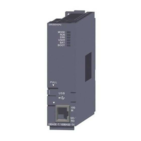
Page 158: Part Names And Settings
SETTINGS AND PROCEDURES BEFORE SYSTEM OPERATION 5.3 Part Names and Settings This section explains the names and settings of each part of the QJ71PB92V. Figure 5.3 QJ71PB92V Appearance Table5.2 Names of Parts Name Description These LEDs indicate the operation status of the QJ71PB92V. Indicator LEDs For details, refer to (1) in this section. - Page 159 SETTINGS AND PROCEDURES BEFORE SYSTEM OPERATION (1) Indicator LEDs Figure 5.4 Indicator LEDs Table5.3 Indicator LEDs Status Description Reference Normally operating Hardware error (watchdog timer error) or power failure Section 9.1 Section 4.1.1 Exchanging I/O data * or during acyclic communication * Flashing Section 4.2.1 SD/RD...
-
Page 160: Self-Diagnostics
SETTINGS AND PROCEDURES BEFORE SYSTEM OPERATION 5.4 Self-diagnostics The self-diagnostics of the QJ71PB92V performs a unit test on the QJ71PB92V. It takes about 15 seconds to complete the self-diagnostics. (1) Self-diagnostics execution procedure The following shows how to execute the self-diagnostics. (a) When the QJ71PB92V is mounted on a redundant system, set the operation mode of the redundant CPU to the Separate or Debug mode. - Page 161 SETTINGS AND PROCEDURES BEFORE SYSTEM OPERATION (2) Execution result of self-diagnostics (a) TEST LED OFF (When normally completed) When the TEST LED turns OFF after execution of self-diagnostics, this indicates a normal completion. (b) TEST and FAULT LEDs ON (When failed) If the TEST and FAULT LEDs are ON after execution of self-diagnostics, this indicates that the diagnostics failed.
-
Page 162: Wiring
SETTINGS AND PROCEDURES BEFORE SYSTEM OPERATION 5.5 Wiring This section explains PROFIBUS cable wiring and relevant precautions. 5.5.1 PROFIBUS cable wiring The following describes the pin assignments of the PROFIBUS interface connector on the QJ71PB92V, the PROFIBUS cable wiring specifications, bus terminator and other information. - Page 163 SETTINGS AND PROCEDURES BEFORE SYSTEM OPERATION (2) PROFIBUS cable The following shows the PROFIBUS cable and wiring specifications. (a) PROFIBUS cable Use a PROFIBUS cable that meets the following specifications (Type A (IEC 61158-2) compliant). Table5.7 PROFIBUS Cable Item Transmission line Applicable cable Shielded twisted pair cable Impedance...
- Page 164 SETTINGS AND PROCEDURES BEFORE SYSTEM OPERATION (4) Wiring specifications for bus terminator When the QJ71PB92V is a terminal station, use a connector with built-in bus terminator that meets the following wiring specifications. VP (6) , min1/4W RxD/TxD-P (3) , min1/4W RxD/TxD-N (8) , min1/4W DGND (5)
-
Page 165: Wiring Precautions
SETTINGS AND PROCEDURES BEFORE SYSTEM OPERATION 5.5.2 Wiring precautions As one of the requirements to give full play to the functions of the QJ71PB92V and make up the system with high reliability, it is necessary to have an external wiring unsusceptible to an influence of noise. -
Page 166: Chapter6 Parameter Setting
PARAMETER SETTING CHAPTER6 PARAMETER SETTING This chapter describes the procedure for setting QJ71PB92V parameters and details of the parameters. In this chapter, parameter settings when programs are created using GX Works2 are described. 6.1 Parameter Setting Procedure The following describes the QJ71PB92V parameter setting procedure. (1) Setting procedure Start Install GX Configurator-DP on the personal computer. - Page 167 PARAMETER SETTING Is the QJ71PB92V mounted to a redundant system? Section 6.7 Set the standby master FDL address in GX Works2. £ Write the parameters set on GX Works2 to a redundant CPU. GX Works2 Version 1 Operating Manual (Common) £...
- Page 168 PARAMETER SETTING Table6.1 Parameter Writing from GX Configurator-DP (Continued) Target for parameter writing Item Description Both systems A and B One system Debug mode When clicking the button, parameters are written to the system of the redundant CPU where cables (including RS-232 cable or USB cable) are connected.
-
Page 169: Operation Mode Setting
PARAMETER SETTING 6.2 Operation Mode Setting This section describes QJ71PB92V operation modes and the procedure for setting the operation mode. The operation mode of the QJ71PB92V can be changed using Operation mode change request area (Un\G2255). POINT When parameters are written to the QJ71PB92V using GX Configurator-DP, the operation mode will be changed as follows: •... - Page 170 PARAMETER SETTING (3) Error codes for the operation mode change failure If the operation mode change is unsuccessfully completed, an error code is stored in the Operation mode change result area (Un\G2256) on the QJ71PB92V. For error codes, refer to Section 9.5.2. (4) Precautions when changing the operation mode (a) When the operation mode change is attempted during I/O data exchange When the operation mode change is attempted during I/O data exchange, the...
-
Page 171: Master Parameters
PARAMETER SETTING 6.3 Master Parameters Set transmission speed for the QJ71PB92V, FDL address and other parameters. (1) Start procedure (a) Right-click the QJ71PB92V icon in the "PROFIBUS Network" window [Master Settings]. Right-click the QJ71PB92V. Figure 6.2 Master Settings window start procedure (2) Setting items Figure 6.3 Master Settings window Table6.3 Master Parameter Setting Items... - Page 172 PARAMETER SETTING Table6.3 Master Parameter Setting Items (Continued) Item Description Set the start I/O number of the QJ71PB92V in three digits. Starting I/O number Setting range: 000 to FE0 (Default: 000 Check this checkbox when sending a clear request to all DP-Slaves from the DP-Master. When a communication error occurs even in one DP-Slave, the clear request is sent to all DP-Slaves Error action flag (Default: not selected).
-
Page 173: Bus Parameters
PARAMETER SETTING 6.4 Bus Parameters Set the PROFIBUS-DP parameters. Normally, the bus parameters are used as default values. When changing some of the bus parameters, make sure of the PROFIBUS-DP standard in advance. (1) Start procedure Click the button in the "Master Settings" window. Bus Parameters (2) Setting items Figure 6.4 Bus Parameter Settings window... - Page 174 PARAMETER SETTING Remark ] (Bit Time) is a unit that expresses the time required for 1-bit data transmission as "1". The actual processing time differs as shown below depending on the transmission speed. • In the case of 1.5 Mbps, 1[T ]=1 / (1.5 )=0.667 •...
-
Page 175: Slave Parameters
PARAMETER SETTING 6.5 Slave Parameters Set parameters for each DP-Slave. (1) Start procedure Right-click the DP-Slave icon in the "PROFIBUS Network" window [Slave Settings]. Right-click the DP-Slave. Figure 6.5 Slave Settings window start procedure (2) Setting items (a) Slave Settings window Figure 6.6 Slave Settings window Table6.6 Slave Parameter Setting Items Item... - Page 176 PARAMETER SETTING Table6.6 Slave Parameter Setting Items (Continued) Item Description Set the minimum response time required for a DP-Slave to send a response frame to the QJ71PB92V. Normally, use the default value. min T_sdr Setting range: 1 to 255 (Unit: , Default: 11 Set the group No.
- Page 177 PARAMETER SETTING (b) DP V1/V2 Slave Parameters window The following window opens when the DP-Slave supports the PROFIBUS-DPV1/ V2 function. • Start procedure Click the button in the "Slave Settings" window until the "DP V1/V2 Next Slave Parameters" window will open. •...
- Page 178 PARAMETER SETTING Table6.7 DP V1/V2 Slave Parameters Setting Items (Continued) Item Description Check this checkbox to enable transmission of the Update Alarm. This setting is available when the DP-Slave supports this function. Update Alarm This item is fixed to be selected depending on the DP-Slave status. Not checked: Disables transmission of the Update Alarm Checked: Enables transmission of the Update Alarm Check this checkbox to enable transmission of the Status Alarm.
-
Page 179: Automatic Refresh Parameters
PARAMETER SETTING 6.6 Automatic Refresh Parameters Set the automatic refresh parameters by which data in the QJ71PB92V buffer memory are automatically transferred to QCPU devices. 6.6.1 Automatic refresh parameter setup procedure The following describes the automatic refresh parameter setup procedure. Start Are the I/O data of all DP-Slaves to be refreshed to the... - Page 180 PARAMETER SETTING Is the auto refresh to be set for an intelligent function module other than the QJ71PB92V using GX Developer or GX Works2? • When using GX Developer Specify a GX Developer project in the "Project Properties" window. • When using GX Works2 GX Configurator-DP Version7 ...
-
Page 181: Automatic Refresh Settings
PARAMETER SETTING 6.6.2 Automatic Refresh Settings (1) CPU Device Access window Set the automatic refresh setting. (a) Start procedure Click the button in the "Master Settings" window. Next (b) Setting items Figure 6.9 CPU Device Access window Table6.8 Automatic refresh setting items Item Description Buffer Devices... - Page 182 PARAMETER SETTING Table6.8 Automatic refresh setting items (Continued) Item Description Buffer Devices Select this radio button to set the same automatic refresh device for all DP-Slaves. Devices are set in the following "Input" or "Output". Input: Device used for the communication of input data is set. (Default: D1000) For a bit device, setting must be made in units of 16 points.
- Page 183 PARAMETER SETTING (2) Slave Specific Buffer Devices window Set the devices used for the communication in units of DP-Slaves. (a) Operation procedure Click the button in the "CPU Device Access" window. Edit Devices (b) Setting items Figure 6.10 Slave Specific Buffer Devices window Table6.9 Automatic refresh setting items for each DP-Slave Item Description...
-
Page 184: Writing Automatic Refresh Parameters
PARAMETER SETTING 6.6.3 Writing Automatic Refresh Parameters Write the automatic refresh parameters to the QCPU. Reset the QCPU after writing the automatic refresh parameters. (1) Start procedure 1) Select "Download to Module" in "Task Panel". 2) Check that the "Update Autorefresh settings" checkbox is selected in the "Select Items for Download"... -
Page 185: Number Of Set Automatic Refresh Parameters
PARAMETER SETTING 6.6.4 Number of set automatic refresh parameters There are restrictions on the number of automatic refresh parameters that can be set for QCPUs. This section describes the number of automatic refresh parameters that can be set for QCPUs and the QJ71PB92V. (1) Number of automatic refresh parameter settings for QCPUs When multiple intelligent function modules are mounted, the number of automatic refresh parameter settings must not exceed the following limit. - Page 186 PARAMETER SETTING (2) Number of automatic refresh parameter settings for the QJ71PB92V The number of automatic refresh parameter settings for the QJ71PB92V varies depending on the automatic refreshing setting method for I/O data. (a) When "Block Transfer" is used When the automatic refresh of I/O data is set by "Block Transfer" (i.e. I/O data of all DP-Slaves are refreshed into the same kind of device), up to five automatic refresh parameters can be set per QJ71PB92V.
- Page 187 PARAMETER SETTING (b) When "Slave Specific Transfer" is used When the automatic refresh of I/O data is set by "Slave Specific Transfer" (i.e. when changing the refresh target device on a per-DP-Slave basis), the following number of automatic refresh parameters can be set per QJ71PB92V. Max.
-
Page 188: Parameter Setting By Gx Works2
PARAMETER SETTING 6.7 Parameter Setting by GX Works2 Set output status at the time of CPU stop error, redundant system support function, and QJ71PB92D-compatible function. (1) Output status setting for the case of a CPU stop error (a) For the QJ71PB92V For the setting method, refer to Section 4.6. - Page 189 PARAMETER SETTING 1) For the redundant system support function Table6.11 Intelligent Function Module Switch Setting Items (For the redundant system support function) Item Description Set the standby master FDL address when the QJ71PB92V is mounted in a redundant system. If the standby master FDL address setting is failed, an error code is stored in the Local station error information area (Un\G23071).
-
Page 190: Chapter7 Programming
PROGRAMMING CHAPTER7 PROGRAMMING When applying the following program examples to the actual system, make sure to examine the applicability of the program and confirm that it will not cause system control problems. POINT When QJ71PB92Vs are mounted on extension base units in a redundant system, dedicated instructions for the QJ71PB92V cannot be used. - Page 191 PROGRAMMING <Redundant system configuration (QJ71PB92V mounted on extension base unit)> Power Power Redundant Redundant supply supply Main base unit module module Tracking cable Power Power QJ71 Extension base unit supply supply PB92V module module Figure 7.1 Installation Positions of the QJ71PB92V and Corresponding Program Examples in This Chapter (Continued) Table7.1 Installation Positions of the QJ71PB92V and Corresponding Program Examples in This Chapter Installation...
-
Page 192: I/O Data Exchange Program Examples
PROGRAMMING 7.1 I/O Data Exchange Program Examples This section explains the examples of I/O data exchange programs. The following system configuration is used as an example for explanations in Sections 7.1.1 to 7.1.3. (1) System configuration example Q25HCPU QJ71PB92V (DP-Master (Class 1)) QX41 DP-Slave DP-Slave... - Page 193 PROGRAMMING (2) Settings (a) QJ71PB92V settings Table7.3 QJ71PB92V Settings Item Description FDL address FDL address 0 Transmission speed 1.5 Mbps Operation mode Communication mode (mode 3) Input data area (for mode 3) 6144 (1800 ) to 6239 (185F I/O data area for FDL address 1 14336 (3800 ) to (Buffer memory)
- Page 194 PROGRAMMING (c) Parameter settings on GX Configurator-DP <Master parameters> The transmission speed is set. Set the FDL address of the QJ71PB92V. Set the I/O No. of the QJ71PB92V. (In 3 digits) <Slave parameters> Set the FDL address of the DP-Slave. Set this for normal DP-Slave.
- Page 195 PROGRAMMING (3) Assignment of devices in program examples The program examples given in Sections 7.1.1 to 7.1.3 use the following device assignments. (a) Devices used by the QJ71PB92V Table7.6 List of Devices for the QJ71PB92V Device Description Device Description Data exchange start completed signal Data exchange start request signal Diagnostic information detection signal Diagnostic information detection reset request signal...
-
Page 196: Program Examples Using Automatic Refresh
PROGRAMMING 7.1.1 Program examples using automatic refresh This section explains a program for the case where the QJ71PB92V communicates with DP-Slaves using automatic refresh. Program examples in this section are based on the system configuration example shown in Section 7.1. (1) Setting automatic refresh parameters Enable the automatic refresh parameters and the data consistency function. - Page 197 PROGRAMMING (2) Program example Not needed when the initial setting is not changed. Turn ON the initial setting execution command Initializes Diagnostic info. invalid setting area Initializes Diagnostic info. non- notification time setting area. Specifies the 2nd temporary slave reservation Turn OFF the initial setting execution command Writes the initial...
- Page 198 PROGRAMMING (a) Program example for control of DP-Slaves Input processing of input data (1st word (b0)) Input processing of input data (1st word (b1)) Writing to output data (1st word) Writing to output data (2nd word) Figure 7.7 Program Example for Control of DP-Slaves (b) Program example for diagnostic information read Reading the diagnostic information...
-
Page 199: Program Example Using Dedicated Instructions
PROGRAMMING 7.1.2 Program example using dedicated instructions This section explains a program in which the QJ71PB92V communicates with DP-Slaves using dedicated instructions. This program example is based on the system configuration example shown in Section 7.1. Not needed when the initial setting is not changed. Turn ON the initial setting execution command Initializes Diagnostic info. - Page 200 PROGRAMMING POINT Confirm that Consistency is disabled with Autom. Refresh enabled. Section 6.3) When the automatic refresh and data consistency functions are enabled, dedicated instructions are not processed. Make sure the checkbox is unchecked. - 11 7.1 I/O Data Exchange Program Examples 7.1.2 Program example using dedicated instructions...
-
Page 201: Program Example Using The Mov Instruction
PROGRAMMING 7.1.3 Program example using the MOV instruction This section explains a program in which the QJ71PB92V communicates with a DP-Slave using the MOV instruction. This program example is based on the system configuration example shown in Section 7.1. Not needed when the initial setting is not changed. Turn ON the initial setting execution command Initializes Diagnostic info. -
Page 202: Program Example For Acquisition Of Extended Diagnostic Error Information
PROGRAMMING 7.2 Program Example for Acquisition of Extended Diagnostic Error Information (1) Assignment of devices in program examples The program example in this section uses the following device assignments. (a) Devices used by the QJ71PB92V Table7.9 List of Devices for the QJ71PB92V Device Description Device... -
Page 203: Program Example For Global Control Function
PROGRAMMING 7.3 Program Example for Global Control Function (1) Assignment of devices in program examples The program example in this section uses the following device assignments. (a) Devices used by the QJ71PB92V Table7.12 List of Devices for the QJ71PB92V Device Description Device Description... -
Page 204: Program Example For Acyclic Communication With Dp-Slaves
PROGRAMMING 7.4 Program Example for Acyclic Communication with DP-Slaves The following explains the request and response formats in acyclic communications, providing a program example. The request and response formats in this section employ offset addresses (in word units). The "offset address" refers to the n-th data in word units starting from the start address of the request instruction No. - Page 205 PROGRAMMING (1) Making a sequence program The following example program is created for executing request instruction No.1. For details on the program example, refer to Section 7.4.5. I/O data exchange normal Reads the execution result and completion status. ( Un\G 25120) DP-Slave I/O data Acceptance...
- Page 206 PROGRAMMING 7.4.1 READ services (Class1_SERVICE, Class2_SERVICE) This section explains the request and response formats of the READ services (Class1_SERVICE, Class2_SERVICE). (1) Request format Table7.15 Request Format Offset Address Description/Set Value Set a request code. (1) In READ service (Class1_SERVICE) + 0 (+ 0 Set value: 1400 (2) In READ service (Class2_SERVICE) Set value: 1410...
- Page 207 PROGRAMMING (2) Response format (a) When normally completed Table7.16 Response Format (When Normally Completed) Offset Address Result A response code is stored. (1) In READ service (Class1_SERVICE) + 0 (+ 0 Stored value: A400 (2) In READ service (Class2_SERVICE) Stored value: A410 (1) In READ service (Class1_SERVICE) 1) The FDL address of the DP-Slave is stored.
- Page 208 PROGRAMMING (b) When failed Table7.17 Response Format (When Failed) Offset Address Result + 0 (+ 0 An error code is stored. ( Section 9.5.3) (1) In READ service (Class1_SERVICE) 1) The FDL address of the DP-Slave is stored. Stored value : 00 to 7D (0 to 125) (2) In READ service (Class2_SERVICE)
- Page 209 PROGRAMMING 7.4.2 WRITE services (Class1_SERVICE, Class2_SERVICE) This section explains the request and response formats of the WRITE services (Class1_SERVICE, Class2_SERVICE). (1) Request format Table7.18 Request Format Offset Address Description/Set Value Set a request code. (1) In WRITE service (Class1_SERVICE) + 0 (+ 0 Set value: 1401 (2) In WRITE service (Class2_SERVICE) Set value: 1411...
- Page 210 PROGRAMMING (2) Response format (a) When normally completed Table7.19 Response Format (When Normally Completed) Offset Address Result A response code is stored. (1) In WRITE service (Class1_SERVICE) + 0 (+ 0 Stored value: A401 (2) In WRITE service (Class2_SERVICE) Stored value: A411 (1) In WRITE service (Class1_SERVICE) 1) The FDL address of the DP-Slave is stored.
- Page 211 PROGRAMMING (b) When failed Table7.20 Response Format (When Failed) Offset Address Result + 0 (+ 0 An error code is stored. ( Section 9.5.3) (1) In WRITE service (Class1_SERVICE) 1) The FDL address of the DP-Slave is stored. Stored value : 00 to 7D (0 to 125) (2) In WRITE service (Class2_SERVICE)
-
Page 212: Initiate Service (Class2_Service)
PROGRAMMING 7.4.3 INITIATE service (Class2_SERVICE) This section explains the request and response formats of the INITIATE service (Class2_SERVICE). (1) Request format Table7.21 Request format Offset Address Description/Set Value Set a request code. + 0 (+ 0 Set value: 1412 Set the FDL address of the DP-Slave to which the network line is connected. + 1 (+ 1 Set value: 0000 to 007D... - Page 213 PROGRAMMING Table7.21 Request format (Continued) Offset Address Description/Set Value 1) Sets D_Type. + 8 (+ 8 The setting range differs depending on the DP-Slave specifications. Check the DP-Slave specifications. 2) Set D_Len. The setting range differs depending on the DP-Slave specifications. Check the DP-Slave specifications.
- Page 214 PROGRAMMING (2) Response format (a) When normally completed Table7.22 Response Format (When Normally Completed) Offset Address Result A response code is stored. + 0 (+ 0 Stored value: A412 + 1 (+ 1 1) The FDL address of the DP-Slave connected to the network is stored. Stored value : 00 to 7D (0 to 125)
- Page 215 PROGRAMMING (b) When failed Table7.23 Response Format (When Failed) Offset Address Result + 0 (+ 0 An error code is stored. ( Section 9.5.3) + 1 (+ 1 1) The FDL address of the DP-Slave connected to the network is stored. Stored value : 00 to 7D (0 to 125)
-
Page 216: Abort Service (Class2_Service)
PROGRAMMING 7.4.4 ABORT service (Class2_SERVICE) This section explains the request and response formats of the ABORT service (Class2_SERVICE). (1) Request format Table7.24 Request Format Offset Address Description/Set Value Set a request code. + 0 (+ 0 Set value: 1413 + 1 (+ 1 1) The FDL address of the DP-Slave to be connected to network is stored. - Page 217 PROGRAMMING (2) Response format (a) When normally completed Table7.25 Response Format (When Normally Completed) Offset Address Result A response code is stored. + 0 (+ 0 Stored value: A413 + 1 (+ 1 1) The FDL address of the DP-Slave connected to the network is stored. Stored value : 00 to 7D (0 to 125)
-
Page 218: Program Example
PROGRAMMING 7.4.5 Program example (1) Settings The example program in this section uses the following example requests. Table7.27 Details of Program Example Item Description Request instruction No. Request instruction No.1 Service name READ service (Class1_SERVICE) DP-Slave FDL address FDL address 2 Data length 16 bytes Slot No. - Page 219 PROGRAMMING (3) Program example Reads the acceptance status and completion status Request code is set. (1400 The FDL address of the target DP-Slave is set (FDL address 2). Data length is set. (16 bytes). Slot No. is set. (0) Index is set. (1) Empty area (0) Executes Acyclic communication...
-
Page 220: Program Example For Alarm Acquisition
PROGRAMMING 7.5 Program Example for Alarm Acquisition The following explains the request and response formats in alarm acquisition, providing a program example. (1) Making a sequence program For details on the program example, refer to Section 7.5.4. I/O data exchange normal Reads alarm status of each station. -
Page 221: Alarm Read Request (Without Ack)
PROGRAMMING 7.5.1 Alarm read request (without ACK) This section explains the request and response formats of the alarm read request (without ACK). (1) Request format Table7.30 Request Format Buffer memory address Description/Set value Set a request code. 26432(6740 Set value: 1500 Set the FDL address of the DP-Slave whose alarm is to be read. - Page 222 PROGRAMMING (2) Response format (a) When normally completed Table7.31 Response Format (When Normally Completed) Buffer memory address Result A response code is stored. 26446(674E Stored value: A500 The FDL address of the DP-Slave from which alarm was read is stored. 26447(674F Stored value: 0000 to 007D...
- Page 223 PROGRAMMING Table7.31 Response Format (When Normally Completed) (Continued) Buffer memory address Result The alarm status and sequence No. are stored. b3 b2 b1 1) Alarm details category is stored. 00 : No additional information 01 : Error detected, and alarm notified from the corresponding slot 26452(6754 10 : No error occurred after alarm notification from the corresponding slot 11 : Error occurred after alarm notification from the corresponding slot...
- Page 224 PROGRAMMING (b) When failed Table7.32 Response Format (When Failed) Buffer memory address Result 26446(674E An error code is stored. ( Section 9.5.4) The FDL address of the DP-Slave from which the alarm was read is stored. 26447(674F Stored value: 0000 to 007D (0 to 125) The read completion status of the alarm data is stored.
-
Page 225: Alarm Ack Request
PROGRAMMING 7.5.2 Alarm ACK request This section explains the request and response formats of the alarm ACK request. The alarm ACK request is used for returning ACK to the DP-Slave after execution of the alarm read request (without ACK) and deleting alarms in the DP-Slave. ACK can be returned for each alarm that was read. - Page 226 PROGRAMMING (2) Response format (a) When normally completed Table7.34 Response Format (When Normally Completed) Buffer memory address Result A response code is stored. 26446(674E Stored value: A501 The FDL address of the DP-Slave that returned ACK is stored. 26447(674F Stored value: 0000 to 007D (0 to 125) The alarm data read completion status and the ACK response completion status are stored.
- Page 227 PROGRAMMING Table7.34 Response Format (When Normally Completed) (Continued) Buffer memory address Result The alarm data that was read by the alarm read request (without ACK) is stored. 26449(6751 ) to 26484(6774 Section 7.5.1 (2)(a)) A response code is stored. 26485(6775 Stored value: A501 The alarm type is stored.
- Page 228 PROGRAMMING (b) When failed Table7.35 Response Format (When Failed) Buffer memory address Result 26446(674E An error code is stored. ( Section 9.5.4) The FDL address of the DP-Slave that returned ACK is stored. 26447(674F Stored value: 0000 to 007D (0 to 125) The alarm data read completion status and the ACK response completion status are stored.
- Page 229 PROGRAMMING Table7.35 Response Format (When Failed) (Continued) Buffer memory address Result The alarm data that was read by the alarm read request (without ACK) is stored. 26449(6751 ) to 26484(6774 Section 7.5.1 (2)(a)) 26485(6775 An error code is stored. Section 9.5.4) (1) When E508 is currently stored in buffer memory address 26485 (6775 Detailed error code 1 is stored.
-
Page 230: Alarm Read Request (With Ack)
PROGRAMMING 7.5.3 Alarm read request (with ACK) This section explains the request and response formats of the alarm read request (with ACK). (1) Request format Table7.36 Request Format Buffer memory address Description/Set value Set a request code. 26432(6740 Set value: 1502 Set the FDL address of the DP-Slave whose alarm is to be read. - Page 231 PROGRAMMING (2) Response format (a) When normally completed Table7.37 Response Format (When Normally Completed) Buffer memory address Result A response code is stored. 26446(674E Stored value: A502 The FDL address of the DP-Slave whose alarm was read is stored. 26447(674F Stored value: 0000 to 007D (0 to 125)
- Page 232 PROGRAMMING Table7.37 Response Format (When Normally Completed) (Continued) Buffer memory address Result The length of the alarm data is stored. (Unit: byte) 26449(6751 Stored value: 1 to 64 The alarm type is stored. Stored Alarm type value A510 Diagnosis alarm A511 Process alarm 26450(6752...
- Page 233 PROGRAMMING Table7.37 Response Format (When Normally Completed) (Continued) Buffer memory address Result A response code is stored. 26485(6775 Stored value: A501 The alarm type is stored. Stored Alarm type value A510 Diagnosis alarm A511 Process alarm 26486(6776 A512 Pull alarm A513 Plug alarm A514...
- Page 234 PROGRAMMING (b) When failed Table7.38 Response Format (When Failed) Buffer memory address Result 26446 (674E An error code is stored. ( Section 9.5.4) The FDL address of the DP-Slave whose alarm was read is stored. 26447 (674F Stored value: 0000 to 007D (0 to 125) The alarm data read completion status and the ACK response completion status are stored.
- Page 235 PROGRAMMING Table7.38 Response Format (When Failed) (Continued) Buffer memory address Result (1) When E506 is currently stored in buffer memory address 26446 (674E Detailed error code 1 is stored. ( Section 9.5.4) 26449(6751 (2) When a value other than E506 is currently stored in buffer memory address 26446 (674E Stored value: FFFF...
-
Page 236: Program Example
PROGRAMMING 7.5.4 Program example (1) Settings The example program in this section uses the following example requests. Table7.39 Details of Program Example Item Description Service name Alarm read request (with ACK) DP-Slave FDL address FDL address 1 (2) Assignment of devices in program example The program examples in this section use the following device assignments. - Page 237 PROGRAMMING (3) Program example Reads the alarm status of each station. Request code is set. (1502 The FDL address of the target DP-Slave is set (FDL address 1). Empty area (0) Executes alarm read. Reads the response code and error code Reads the execution result Alarm read completion processing...
-
Page 238: Program Example For Time Control Over Dp-Slaves
PROGRAMMING 7.6 Program Example for Time Control over DP-Slaves This section explains the request and response formats in the time control function, providing a program example. (1) Making a sequence program For details on the program example, refer to Section 7.6.4. I/O data exchange normal... -
Page 239: Time Data Read Request
PROGRAMMING 7.6.1 Time data read request This section explains the request and response formats of the time data read request. (1) Request format Table7.43 Request Format Buffer memory address Description/Set value Set a request code. 26784(68A0 Set value: 1600 26785(68A1 ) to Empty area (Write 0000 26792(68A8... - Page 240 PROGRAMMING (2) Response format (a) When normally completed Table7.44 Response Format (When Normally Completed) Buffer memory address Result A response code is stored. 26800(68B0 Stored value: A600 The year is stored. 26801(68B1 Stored value: 1984 to 2036 The month is stored. 26802(68B2 Stored value: 1 to 12 The day is stored.
-
Page 241: Time Data Write Request (Utc Format)
PROGRAMMING 7.6.2 Time data write request (UTC format) This section explains the request and response formats of the time data write request (UTC format). (1) Request format Table7.46 Request Format Buffer memory address Description/Set value Set a request code. 26784(68A0 Set value: 1601 Set the UTC second (year + month + day + hour + minute + second). - Page 242 PROGRAMMING (2) Response format (a) When normally completed Table7.47 Response Format (When Normally Completed) Buffer memory address Result A response code is stored. 26800(68B0 Stored value: A601 26801(68B1 ) to Empty area 26812(68BC Stored value: 0000 (b) When failed Table7.48 Response Format (When Failed) Buffer memory address Result 26800(68B0...
-
Page 243: Time Data Write Request
PROGRAMMING 7.6.3 Time data write request This section explains the request and response formats of the time data write request. (1) Request format Table7.49 Request Format Buffer memory address Description/Set value Set a request code. 26784(68A0 Set value: 1602 Set the year. 26785(68A1 Set value: 1984 to 2036 Set the month. - Page 244 PROGRAMMING (2) Response format (a) When normally completed Table7.50 Response Format (When Normally Completed) Buffer memory address Result A response code is stored. 26800(68B0 Stored value: A602 26801(68B1 ) to Empty area 26812(68BC Stored value: 0000 (b) When failed Table7.51 Response Format (When Failed) Buffer memory address Result 26800(68B0...
-
Page 245: Program Example
PROGRAMMING 7.6.4 Program example (1) Settings The example program in this section uses the following example requests. Table7.52 Details of Program Example Item Description Service name Time data write request (2) Assignment of devices in program example The program example in this section uses the following device assignments. (a) Devices used by the QJ71PB92V Table7.53 List of Devices for the QJ71PB92V Device... - Page 246 PROGRAMMING (3) Program example Request code is set (1602 Year is set. (2005) Month is set. (July) Day is set (1st). Hour is set. (10 o'clock). Minute is set. (0 minutes). Second is set. (0 seconds) 1/000 second value is set. (0) Clock status is set.
-
Page 247: Program Example For Temporary Slave Reservation
PROGRAMMING 7.7 Program Example for Temporary Slave Reservation Program example for temporary slave reservation, refer to section 7.1.1 to 7.1.3. POINT The program for the temporary slave reservation must be executed before turning ON the Data exchange start request signal (Y00). ( Section 7.1.1 to 7.1.3) 7.7 Program Example for Temporary Slave Reservation - 58... -
Page 248: Program Example When Mounting The Qj71Pb92V On A Melsecnet/H Remote I/O Network
PROGRAMMING 7.8 Program Example When Mounting the QJ71PB92V on a MELSECNET/H Remote I/O Network This section presents a program example for the case where the QJ71PB92V is mounted and used on a MELSECNET/H remote I/O station. 7.8.1 Program example for the I/O data exchange function (When mounted on a remote I/O station) This section explains a program example for the I/O data exchange function when the QJ71PB92V is mounted and used on a MELSECNET/H remote I/O station. -
Page 249: Program Example For The I/O Data Exchange Function (When Mounted On A Remote I/O Station)
PROGRAMMING * 1 Modules are installed in order from slot 0 as shown in the figure, and the following start I/O Nos. are to be set. Figure 7.21 I/O Assignment in Program Example (Remote Master Station) Table7.56 Assignment of Input and Output Signals (Remote Master Station) Module Input signal Output signal... - Page 250 PROGRAMMING (2) MELSECNET/H (remote I/O network) settings (a) Remote master station (QJ71LP21-25) settings Table7.58 Remote Master Station Settings Item Description Station No. Station No. : 0 Transmission speed 25 Mbps (MODE 4) Operation mode Online (b) Remote I/O station (QJ72LP25-25) settings Table7.59 Remote I/O Station Settings Item Description...
- Page 251 PROGRAMMING (4) Assignment of devices in program example The program examples in this section use the following device assignments. (a) Devices used by the QJ71PB92V Table7.60 List of Devices for the QJ71PB92V Device Description Device Description X1000 Data exchange start completed signal Y1000 Data exchange start request signal X101B...
- Page 252 PROGRAMMING (5) Program example (a) Interlock program example for remote master station and remote I/O station Provide interlocks depending on the link status of the remote master station (host station) and remote I/O station (other station). The following example shows a communication program interlock using the link status (SB47, SB49) of the remote master station and the link status (SW70 b0, SW74 b0, SW78 b0) of the remote I/O station (station No.
- Page 253 PROGRAMMING (b) I/O data exchange program example POINT After execution of the REMFR/REMTO instruction, it requires several scans until read/write of actual data is completed. Not required when initial settings are not changed Initializing Diagnostic information invalid setting area Processing for failed initialization Initializing Diagnostic information non-...
- Page 254 PROGRAMMING Reading input data Processing for failure of input data reading Reading Slave status area Processing for failure of Slave status area reading Section 7.1.1 (2)(a) Program for control of DP-Slaves ( Writing output data Processing for failure of output data writing Not required when initial settings are not changed Figure 7.25 Program Example for the I/O Data Exchange Function (When Mounted on a Remote I/O Station) (Continued) - 65...
-
Page 255: Other Precautions
PROGRAMMING 7.8.2 Other precautions When programming for the QJ71PB92V on a MELSECNET/H remote I/O station, pay attention to the following. (1) QJ71PB92V I/O signals I/O signals of the QJ71PB92V are refreshed into link devices (LX/LY) on the remote I/ O station and then transferred to the remote master station. Make the link devices (LX/LY) of the remote master station refreshed into the devices (X/Y) of the QCPU and use them in sequence programs. -
Page 256: Program Examples For Use In The Redundant System
PROGRAMMING 7.9 Program Examples for Use in the Redundant System This section explains program examples for the case where the QJ71PB92V is mounted in a redundant system. (1) Making a sequence program The following explains the sequence program creation for the case where the QJ71PB92V is mounted in a redundant system. - Page 257 PROGRAMMING (b) When keeping the I/O data exchange function enabled after system switching 1) Initial setting The initial setting is performed in the timing of "ON for 1 scan only after switching system from standby to control" (SM1518). Initial setting for QJ71PB92V startup Initializes Diagnostic info.
- Page 258 PROGRAMMING 2) Keeping output data To keep output data after system switching, perform the following. • Processing of the QJ71PB92V in the control system (Before system switching) Write the output data to the Output data area (Un\G14336 to Un\G18431) using devices. Tracking-transfer the output data stored in the devices.
- Page 259 PROGRAMMING (2) Precautions (a) Operation mode change To change the operation mode of the QJ71PB92V, set the redundant CPU in Separate or Debug mode and refer to the program example in Section 7.1.1 (2) (c). For precautions for changing the operation mode of the QJ71PB92V, refer to Section 6.2.
-
Page 260: I/O Data Exchange Program Examples
PROGRAMMING 7.9.1 I/O Data Exchange Program Examples I/O data exchange can be continued after system switching. This section explains program examples for continuing I/O data exchange in the case of system switching. The following system configuration is used as an example for explanations in Sections 7.9.1 to 7.9.7. - Page 261 PROGRAMMING (2) Settings (a) QJ71PB92V settings Table7.65 QJ71PB92V Settings Item Description FDL address 0 Control master FDL address FDL address FDL address 1 Standby master FDL address Transmission speed 1.5Mbps Operation mode Communication mode (mode 3) Input data area (for mode 3) 6144 (1800 ) to 6239 (185F I/O data area for FDL address 2...
- Page 262 PROGRAMMING (c) Parameter settings in GX Configurator-DP <Master parameters> Set the transmission speed. Set the control master FDL address. Set the I/O No. of the QJ71PB92V. (In 3 digits) Set a Slave Watchdog timer value that meets the calculation formula shown in Section 4.8 (5).
- Page 263 PROGRAMMING (d) Parameter settings in GX Works2 <Intelligent function module switch setting> Set a standby master FDL address. <Tracking settings> Select "Device detail settings". Set tracking devices. Figure 7.34 I/O Data Exchange Parameter Setting Example (GX Works2) * 1 For tracking devices used for continuing respective functions of the QJ71PB92V, refer to (4) in this section and sections 7.9.2 to 7.9.7.
- Page 264 PROGRAMMING (3) Device assignments in program example The program examples in this section use the following device assignments. (a) Devices used by the QJ71PB92V Table7.68 List of Devices for the QJ71PB92V Device Description Device Description Data exchange start completed signal Data exchange start request signal Diagnostic information detection signal Diagnostic information detection reset request signal...
- Page 265 PROGRAMMING (4) Tracking devices for continuously using the functions in the case of system switching In the I/O data exchange program example, data in the following devices are tracking- transferred. (a) Devices whose data are tracking-transferred by I/O data exchange programs Data in the following devices are tracking-transferred: •...
- Page 266 PROGRAMMING (5) Program examples (a) When using automatic refresh This section explains a program for the case where the QJ71PB92V communicates with DP-Slaves using automatic refresh. 1) Setting automatic refresh parameters The setting is the same as in Section 7.1.1 (1). 2) I/O data exchange program example (Automatic refresh) Not needed when the initial setting is not changed.
- Page 267 PROGRAMMING (b) When using dedicated instructions This section explains a program in which the QJ71PB92V communicates with DP- Slaves using dedicated instructions. Not needed when the initial setting is not changed. Turn ON the initial setting execution command Initializes Diagnostic info. invalid setting area Initializes Diagnostic info.
- Page 268 PROGRAMMING POINT Confirm that Consistency is disabled with Autom. Refresh enabled. Section 6.3) When the automatic refresh and data consistency functions are enabled, dedicated instructions are not processed. Make sure the checkbox is unchecked. - 79 7.9 Program Examples for Use in the Redundant System 7.9.1 I/O Data Exchange Program Examples...
- Page 269 PROGRAMMING (c) When using the MOV instruction This section explains a program in which the QJ71PB92V communicates with a DP-Slave using the MOV instruction. Not needed when the initial setting is not changed. Turn ON the initial setting execution command Initializes Diagnostic info.
-
Page 270: Program Example For Acquisition Of Extended Diagnostic Error Information
PROGRAMMING 7.9.2 Program example for acquisition of extended diagnostic error information If a system switching occurs, acquisition of the extended diagnostic error information is disabled. After the system switching, only the extended diagnostic error information that is newly generated after the switching can be obtained. For a program example for acquisition of extended diagnostic information, refer to section 7.2. -
Page 271: Program Example For Global Control Function
PROGRAMMING 7.9.3 Program example for global control function If a system switching occurs during execution of the global control function, the processing cannot be continued. This section explains a program example for reexecuting the global control function in the case of system switching. (1) Device assignments in program example (a) Devices used by the QJ71PB92V The devices are the same as those in Section 7.3 (1) (a). -
Page 272: Program Example For Acyclic Communication With Dp-Slaves
PROGRAMMING 7.9.4 Program example for acyclic communication with DP-Slaves If a system switching occurs, the function of the acyclic communication with DP-Slaves cannot be continued. In redundant systems, do not use the acyclic communication with DP-Slaves. To use the function, pay attention to the descriptions given below and fully examine the possible operations in advance. -
Page 273: Program Example For Alarm Acquisition
PROGRAMMING 7.9.5 Program example for alarm acquisition If a system switching occurs, the function of the alarm acquisition cannot be continued. In redundant systems, do not use the alarm acquisition. To use the function, pay attention to the this section and fully examine the possible operations in advance. - Page 274 PROGRAMMING (c) Tracking devices for reexecuting the function in the case of system switching In the program for the time control over DP-Slaves, data in the following devices are tracking-transferred. • Start command device by which the Time control start request signal (Y19) is turned ON •...
-
Page 275: Program Example For Temporary Slave Reservation
PROGRAMMING 7.9.7 Program example for temporary slave reservation If a system switching occurs during execution of the temporary slave reservation function, the processing cannot be continued. The following explains a program example for reexecuting temporary slave reservation function after system switching. (1) Device assignments in program example The devices assignment are the same as those in Section 7.9.1. -
Page 276: Chapter8 Dedicated Instructions
DEDICATED INSTRUCTIONS CHAPTER8 DEDICATED INSTRUCTIONS A "dedicated instruction" is defined as an instruction designed to make programming easy for use of the intelligent function module functionality. This chapter describes the dedicated functions available for the QJ71PB92V. (1) List of dedicated functions The following list shows the dedicated instructions available for the QJ71PB92V. -
Page 277: Precautions For Dedicated Instructions
DEDICATED INSTRUCTIONS 8.1 Precautions for Dedicated Instructions (1) Before executing a dedicated instruction Before executing a dedicated instruction, be sure to confirm the following. (a) Turn ON the Data consistency start request signal (Y0C) Before executing a dedicated instruction, turn ON the Data consistency start request signal (Y0C). - Page 278 DEDICATED INSTRUCTIONS (3) Execution timing Execute the BBLKRD and BBLKWR instructions all the time. While the QJ71PB92V is implementing the data consistency function, the dedicated instruction is not processed (not executed). ( Section 4.5) Therefore, I/O data may not be read or written in a program where either of the instructions is executed only once at the rising or falling edge of the pulse.
-
Page 279: Bblkrd
DEDICATED INSTRUCTIONS 8.2 G. BBLKRD Table8.3 Device Usable in the BBLKRD Instruction Usable device Link direct device Intelligent Internal device Index function Set data (System, user) File Constant register Other module device register K, H Word Word [Instruction [Execution symbol] condition] Command G. - Page 280 DEDICATED INSTRUCTIONS Program example At the timing of M10 = ON, data of 960 points are read to D0 to D959 from address 6144 (1800 ) of the Input data area (for mode 3) of the QJ71PB92V (module start I/O No.0) with data consistency ensured.
-
Page 281: Bblkwr
DEDICATED INSTRUCTIONS 8.3 G. BBLKWR Table8.5 Device Usable in the BBLKWR Instruction Usable device Link direct device Intelligent Internal device Index function Set data (System, user) File Constant register Other module device register K, H Word Word [Instruction [Execution symbol] condition] Command G. - Page 282 DEDICATED INSTRUCTIONS Program example At the timing of M 10 = 10, data of 960 points in D0 to D959 are written to the Output data area (for mode 3) of the QJ71PB92V (module start I/O No.0) with data consistency ensured, starting from address 14336 (3800 Figure 8.6 BBLKWR Instruction Program Example 8.3 G.
-
Page 283: Chapter9 Troubleshooting
TROUBLESHOOTING CHAPTER9 TROUBLESHOOTING This chapter explains the troubleshooting and error codes of the QJ71PB92V. Before troubleshooting the QJ71PB92V, check that no errors have occurred on the QCPU or MELSECNET/H remote I/O network. If any error is identified, check the error details and take corrective actions. For the troubleshooting in Section 9.1 to 9.4, refer to the following flowchart. -
Page 284: Error Check Using The Leds And Corrective Actions
TROUBLESHOOTING 9.1 Error Check Using the LEDs and Corrective Actions This section explains how to check errors by the LEDs or by checking the LED status on GX Works2. (1) Causes and actions The following table summarizes causes that can be thought from the LED status of the QJ71PB92V and corrective actions to be taken. - Page 285 TROUBLESHOOTING (2) Checking the LED status on GX Works2 The status of the LEDs for the QJ71PB92V can be also checked on the H/W Information window (H/W LED information) of GX Works2. [Diagnostics] [System monitor] button Module's Detailed Information button H/W Information Figure 9.2 H/W Information window Table9.2 Values Displayed at H/W LED Information...
-
Page 286: When Parameters Cannot Be Written From Gx Configurator-Dp
TROUBLESHOOTING 9.2 When Parameters cannot be Written from GX Configurator-DP The following shows the troubleshooting procedures to be taken when parameters cannot be written to the QJ71PB92V from GX Configurator-DP. (1) When the QJ71PB92D-compatible function is disabled Parameters cannot be written. Is the DP-Master set to "QJ71PB92V"... - Page 287 TROUBLESHOOTING (2) When the QJ71PB92D-compatible function is enabled Parameters cannot be written. GX Configurator-DP Version 7.00A cannot be used. Is any other than Upgrade the GX Configurator-DP Version 7.00A to Version GX Configurator-DP Version 7.00A 7.01B or later. (Please consult your local Mitsubishi being used? representative.) Is the DP-Master set to...
-
Page 288: When Communication With Dp-Slaves Is Not Possible
TROUBLESHOOTING 9.3 When Communication with DP-Slaves Is Not Possible The following shows the troubleshooting procedures when communications between the QJ71PB92V and DP-Slaves are not possible. Communication with DP-Slave is not possible. Check the PROFIBUS cable connections. Are PROFIBUS cables wired Section 5.5 correctly? Is a bus... - Page 289 TROUBLESHOOTING Are the parameter settings consistent Correct the parameters and write them again. with actual slave configurations? Is the QJ71PB92V's Data exchange start Turn ON the Data exchange start request signal (Y00). request signal (Y00) ON? Check the diagnostic information of the faulty DP-Slave, and take corrective actions.
-
Page 290: Troubleshooting In The Redundant System
TROUBLESHOOTING 9.4 Troubleshooting in the Redundant System This section explains the troubleshooting procedures for the case where the QJ71PB92V is mounted in a redundant system. 9.4.1 When output data turn OFF or momentarily OFF in system switching The following shows the troubleshooting steps for the case where output data turn OFF or momentarily OFF in system switching. -
Page 291: When The Fault Led Of The Qj71Pb92V In The New Control System Is On
TROUBLESHOOTING 9.4.2 When the FAULT LED of the QJ71PB92V in the new control system is The following shows how to recover the QJ71PB92V in the new control system when its FAULT LED is ON. Start While the redundant system is operating in Backup mode, check that the QJ71PB92V is running in the following status. -
Page 292: Maintenance Of The Qj71Pb92V In The Standby System
TROUBLESHOOTING 9.4.3 Maintenance of the QJ71PB92V in the standby system The following shows how to perform maintenance in the standby system during Backup mode operation and to restart the redundant system operation. Maintenance Maintenance • Sequence program modification • Parameter change in GX Configurator-DP or GX Works2 •... - Page 293 TROUBLESHOOTING Start Connect GX Works2 to the control system CPU. On the Redundant operation screen of GX Works2, select Separate mode for Operation mode of the redundant CPU. Stop the system for which maintenance is to be performed (standby system CPU). Disconnect the PROFIBUS cable connected to the QJ71PB92V in the standby system.
- Page 294 TROUBLESHOOTING Turn the maintenance-completed system (standby system CPU) to RUN. Connect the PROFIBUS cable to the standby system QJ71PB92V. (To the previous page) Connect GX Works2 to the control system CPU. Execute system switching from GX Works2. 1. Turn ON the manual switching enable flag (SM1592) of the control system CPU.
-
Page 295: Error Codes
TROUBLESHOOTING 9.5 Error Codes This section explains the error codes that are output on the QJ71PB92V. The QJ71PB92V error codes are classified by groups with error No. The following table lists the groups of the error codes and the areas where they are stored. Table9.3 Error Code Classifications Storage Location Reference... -
Page 296: Error Codes E200H To E2Ffh (Error Codes Generated When Reading Extended Diagnostic Information)
TROUBLESHOOTING Error codes E200 to E205 9.5.1 Error codes E200 to E2FF (Error codes generated when reading extended diagnostic information) Table9.4 Error codes E200 to E2FF Error Code Error Description Action E200 The specified FDL address is out of the range. E201 No FDL address has been specified. -
Page 297: Error Codes E300H To E3Ffh (Error Codes Generated When Switching Operation Mode)
TROUBLESHOOTING Error codes E300 to E3A3 9.5.2 Error codes E300 to E3FF (Error codes generated when switching operation mode) Table9.5 Error codes E300 to E3FF Error Code Error Description Action Check if the operation mode set in Operation mode E300 The specified operation mode is invalid. -
Page 298: Error Codes E400H To E4Ffh (Error Codes Generated During Acyclic Communication)
TROUBLESHOOTING Error codes E400 to E430 9.5.3 Error codes E400 to E4FF (Error codes generated during acyclic communication) Table9.6 Error codes E400 to E4FF Error Code Error Description Action E400 The FDL address of the target DP-Slave is out of the range. The FDL address specified for the target DP-Slave belongs Check if the specified FDL address is correct, and retry. - Page 299 TROUBLESHOOTING Error codes E431 to E468 Table9.6 Error codes E400H to E4FFH (Continued) Error Code Error Description Action Resource error was detected during read processing on the E431 DP-Slave side. Resource error was detected during write processing on the E432 DP-Slave side.
- Page 300 TROUBLESHOOTING Error codes E469 to E4A9 Table9.6 Error codes E400H to E4FFH (Continued) Error Code Error Description Action E469 Incorrect data type was detected on the DP-Slave side. Access to an access-disabled area was attempted from E46A the DP-Slave side. E46B Access is not available on the DP-Slave side.
- Page 301 TROUBLESHOOTING Error codes E4AA to E4DE Table9.6 Error codes E400H to E4FFH (Continued) Error Code Error Description Action Access to an access-disabled area was attempted from E4AA the DP-Slave side. E4AB Access is not available on the DP-Slave side. E4AC The access was rejected on the DP-Slave side.
- Page 302 TROUBLESHOOTING Error codes E4DF to E4E3 Table9.6 Error codes E400H to E4FFH (Continued) Error Code Error Description Action (1) Check the PROFIBUS cable wiring status and start completion status of the DP-Slave, and then retry. For the start completion status of the DP-Slave, refer to the manual for the DP-Slave.
-
Page 303: Error Codes E500H To E5Ffh (Error Codes Generated When Reading Alarms)
TROUBLESHOOTING Error codes E500 to E563 9.5.4 Error codes E500 to E5FF (Error codes generated when reading alarms) Table9.7 Error codes E500 to E5FF Error Code Error Description Action E500 The FDL address of the target DP-Slave is out of the range. The FDL address specified for the target DP-Slave belongs E501 to a non-configured station. - Page 304 TROUBLESHOOTING Error codes E564 to E59D Table9.7 Error codes E500H to E5FFH (Continued) Error Code Error Description Action E564 Application error was detected on the DP-Slave side. Request-not-supported error was detected on the DP-Slave E565 side. E566 Incorrect index was detected on the DP-Slave side E567 Incorrect data length was detected on the DP-Slave side.
- Page 305 TROUBLESHOOTING Error codes E59E to E5A2 Table9.7 Error codes E500H to E5FFH (Continued) Error Code Error Description Action Check the PROFIBUS cable wiring status and start completion status of the DP-Slave, and then retry. When Acyclic communications have been continuously The DP-Slave is not able to respond.
-
Page 306: Error Codes E600H To E6Ffh (Error Codes Generated When Executing Time Control)
TROUBLESHOOTING Error codes E600 to E62D 9.5.5 Error codes E600 to E6FF (Error codes generated when executing time control) Table9.8 Error codes E600 to E6FF Error Code Error Description Action E600 The request code is incorrect. Check if the request code is correct, and retry. After writing clock data from another time master, execute E601 No clock data have been written from another time master. -
Page 307: Error Codes F100H To Fbffh (Local Diagnostic Information Of The Qj71Pb92V)
TROUBLESHOOTING Error codes F100 to F10F 9.5.6 Error codes F100 to FBFF (Local diagnostic information of the QJ71PB92V) Table9.9 Error codes F100 to FBFF Error Code LED Status Error Description Action FDL address No. of a DP-Slave is Check the FDL addresses of the DP-Master and F100 FAULT LED ON duplicated with that of the DP-Master in the... - Page 308 TROUBLESHOOTING Error codes F110 to FB01 Table9.9 Error codes F100 to FBFF (Continued) Error Code LED Status Error Description Action Although Data consistency start request Modify the sequence program so that the BBLKRD F110 signal (Y0C) is ON, the BBLKRD instruction is executed when Data consistency start instruction is not executed.
- Page 309 TROUBLESHOOTING Error codes FB02 to FB04 Table9.9 Error codes F100 to FBFF (Continued) Error Code LED Status Error Description Action Reset the following items: "FDL address" in the master parameter setting of The FDL address of the control master is FB01 FAULT LED ON GX Configurator-DP (...
-
Page 310: How To Return The Qj71Pb92V To Its Factory-Set Conditions
TROUBLESHOOTING 9.6 How to Return the QJ71PB92V to Its Factory-set Conditions This section explains how to return the QJ71PB92V to its factory-set condition. This procedure initializes the flash ROM of the QJ71PB92V. Perform the following procedure, for example, when parameters in the flash ROM are corrupted (The PRM SET LED is flashing). - Page 311 TROUBLESHOOTING (3) Reapply power to or reset the QCPU The PRM SET LED on the QJ71PB92V turns ON, and the QJ71PB92V starts in the Parameter setting mode (mode 1). Write the QJ71PB92V parameters on GX Configurator-DP. 9.6 How to Return the QJ71PB92V to Its Factory-set Conditions - 29...
- Page 312 TROUBLESHOOTING Memo - 30 9.6 How to Return the QJ71PB92V to Its Factory-set Conditions...
-
Page 313: Appendices
APPENDICES APPENDICES Appendix 1 External Dimensions 27.4 Unit : mm Figure APPX.1 External Dimensions APPX Appendix 1 External Dimensions... - Page 314 APPENDICES Memo Appendix 1 External Dimensions...
- Page 315 INDEX Diagnostic information area (for mode 3) ..3-39 Diagnostic information detection reset request signal ABORT service (Class2_SERVICE) ..7-27 (Y01) ........3-7 Acquisition of diagnostic and/or extended diagnostic Diagnostic information detection signal (X01) .
- Page 316 Local FDL address display area ... . . 3-22 Slave status area (Normal communication detection) Local station error information area ..3-21 .
- Page 317 WARRANTY Please confirm the following product warranty details before using this product. 1. Gratis Warranty Term and Gratis Warranty Range If any faults or defects (hereinafter "Failure") found to be the responsibility of Mitsubishi occurs during use of the product within the gratis warranty term, the product shall be repaired at no cost via the sales representative or Mitsubishi Service Company.
- Page 318 PROFIBUS is a trademark of PROFIBUS Nutzerorganisation e.V. The company names, system names and product names mentioned in this manual are either registered trademarks or trademarks of their respective companies. In some cases, trademark symbols such as '™' or '®' are not specified in this manual. SH(NA)-080572ENG-F...
- Page 320 SH(NA)-080572ENG-F(1809)MEE MODEL: QJ71PB92V-U-SY-E MODEL CODE: 13JR84 HEAD OFFICE : TOKYO BUILDING, 2-7-3 MARUNOUCHI, CHIYODA-KU, TOKYO 100-8310, JAPAN NAGOYA WORKS : 1-14 , YADA-MINAMI 5-CHOME , HIGASHI-KU, NAGOYA , JAPAN When exported from Japan, this manual does not require application to the Ministry of Economy, Trade and Industry for service transaction permission.
Need help?
Do you have a question about the Melsec Q Series and is the answer not in the manual?
Questions and answers