Table of Contents
Advertisement
Quick Links
Advertisement
Table of Contents
Troubleshooting

Related Manuals for Mitsubishi NZ2GFCF-D62PD2


Summary of Contents for Mitsubishi NZ2GFCF-D62PD2
-
Page 3: Safety Precautions
SAFETY PRECAUTIONS (Read these precautions before using this product.) Before using this product, please read this manual and the relevant manuals carefully and pay full attention to safety to handle the product correctly. The precautions given in this manual are concerned with this product only. For the safety precautions of the programmable controller system, refer to the user's manual for the CPU module used. - Page 4 [Design Precautions] CAUTION ● Do not install the communication cables together with the main circuit lines or power cables. Keep a distance of 100mm or more between them. Failure to do so may result in malfunction due to noise. ● Do not install the control lines together with the main circuit lines or power cables. Keep a distance of 150mm or more between them.
- Page 5 ● Connectors for external devices must be crimped with the tool specified by the manufacturer, or must be correctly soldered. Securely connect the connector to the module. ● Mitsubishi programmable controllers must be installed in control panels. Wiring and replacement of a module must be performed by qualified maintenance personnel with knowledge of protection against...
- Page 6 [Startup and Maintenance Precautions] WARNING ● Do not touch any terminal while power is on. Doing so will cause electric shock or malfunction. ● Shut off the external power supply (all phases) used in the system before cleaning the module or retightening the terminal block screws or connector screws.
-
Page 7: Conditions Of Use For The Product
PRODUCT in one or more of the Prohibited Applications, provided that the usage of the PRODUCT is limited only for the specific applications agreed to by Mitsubishi and provided further that no special quality assurance or fail-safe, redundant or other safety features which exceed the general specifications of the PRODUCTs are required. -
Page 8: Introduction
When applying the program examples introduced in this manual to an actual system, ensure the applicability and confirm that it will not cause system control problems. Target module: NZ2GFCF-D62PD2 Remark Unless otherwise specified, this manual describes the program examples in which the remote I/O signals and remote registers are assigned for a high-speed counter module as follows. -
Page 9: Relevant Manuals
RELEVANT MANUALS (1) CC-Link IE Field Network (relevant) manuals When using the CC-Link IE Field Network for the first time, refer to CC-Link IE Field Network Master/Local Module User's Manual first. The following shows the structure of the CC-Link IE Field Network manuals. Manual name Description <manual number (model code)>... -
Page 10: Table Of Contents
CONTENTS CONTENTS SAFETY PRECAUTIONS ............. 1 CONDITIONS OF USE FOR THE PRODUCT . - Page 11 6.6.2 Connectors for external devices..........6.6.3 I/O interfaces with external devices .
- Page 12 CHAPTER 9 PROGRAMMING Precautions for Programming ..........Procedure for Programming .
-
Page 13: Manual Page Organization
MANUAL PAGE ORGANIZATION In this manual, pages are organized and the symbols are used as shown below. The following illustration is for explanation purpose only, and should not be referred to as an actual documentation "" is used for screen names and items. The chapter of the current page is shown. -
Page 14: Term
TERM Unless otherwise specified, this manual uses the following terms. Term Description CC-Link IE Field Network A high-speed and large-capacity open field network that is based on Ethernet (1000BASE-T) GX Works2 The product name of the software package for the MELSEC programmable controllers The abbreviation for ZP.REMFR. - Page 15 Term Description Bit data that indicates the operating status and data link status of a module on CC-Link IE Field Link special relay (SB) Network Bit data that indicates the operating status and data link status of a module on CC-Link IE Field Link special register (SW) Network A process of selecting paths for communication with other networks.
-
Page 16: Packing List
PACKING LIST The following items are included in the package of this product. Before use, check that all the items are included. High-speed counter module Module Before Using the Product... -
Page 17: Chapter 1 High-Speed Counter Module
CHAPTER 1 HIGH-SPEED COUNTER MODULE CHAPTER 1 HIGH-SPEED COUNTER MODULE This chapter describes the operation, the application, and the features of the high-speed counter module. The high-speed counter module is a remote device station of the CC-Link IE Field Network whose maximum counting speed of input pulse is 8Mpps (with differential input and 4 multiples of 2 phases). -
Page 18: Application
Application This module performs controls which are applicable to various applications by executing various functions according to count values of pulses input from the external device. The following describes an application example. Temporarily stops the inverter. (Coincidence output) Inverter Inverter Encoder Encoder (pulse generator) -
Page 19: Features
CHAPTER 1 HIGH-SPEED COUNTER MODULE Features (1) Available flexible system configuration Adopting the connection block type enables the combination of the main module and extension module. Because various extension modules can be connected, a flexible configuration can be achieved. In addition, a poor contact of the extension module can be found promptly because the main module always monitors the connection status of the extension module. - Page 20 Programming is reduced since the parameter can be configured on the window with the CC IE Field configuration of GX Works2. In addition, setting status and operation status of modules can be checked easily. Parameters for the NZ2GFCF-D62PD2 NZ2GFCF-D62PD2 Select...
- Page 21 CHAPTER 1 HIGH-SPEED COUNTER MODULE (5) Pulse measurement function Pulses can be measured with 100ns measurement resolution. The pulse width (ON width/OFF width) can be precisely measured. Various pulse measurement applications such as the workpiece length measurement or the transport/processing speed management of various types of transport equipment and processing equipment are available.
- Page 22 (7) Cam switch function According to the input count present value, the ON/OFF status of output can be set for every preset point without any program. More precise ON/OFF control is available without scan time effect. An extension output module is required for using this function. Output 1 Output 2 Output 3...
-
Page 23: Chapter 2 Part Names
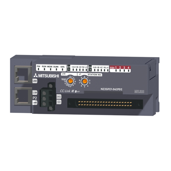
CHAPTER 2 PART NAMES CHAPTER 2 PART NAMES This chapter describes the part names of the high-speed counter module. *1 Do not remove this seal because it is used for a maintenance purpose. - Page 24 Name Description A rotary switch for the following setting and test • Station Number Setting ( Page 55, Section 6.1) Station number setting • Unit Test ( Page 227, Section 11.4) switch When operating the station number setting switch, use a slotted screwdriver with 3.5mm or less width of the tip.
- Page 25 CHAPTER 2 PART NAMES Name Description PORT1 connector for CC-Link IE Field Network (RJ45 connector) Connect an Ethernet cable. ( Page 65, Section 6.5) There are no restrictions on the connection order of the cables for the "P1" connector and "P2" connector.
- Page 26 (1) Module status and LED status The following table lists the correspondence between the module status and the LED status. LED status Module status Data link status PW LED RUN LED MODE LED D LINK LED ERR. LED Disconnecting Disconnection Data link in operation Data link in operation Reserved station...
-
Page 27: Chapter 3 Specifications
Do not use or store the high-speed counter module under pressure higher than the atmospheric pressure of altitude 0m. Doing so may cause malfunction. When using the high-speed counter module under pressure, please consult your local Mitsubishi representative. If the environment satisfies the operating ambient temperature, operating ambient humidity and other conditions, the module can be used even outside the control panel. - Page 28 To use the high-speed counter module complying with the EMC Directive, refer to "EMC and Low Voltage Directives" in this manual. ( Page 286, Appendix 5)
-
Page 29: Performance Specifications
CHAPTER 3 SPECIFICATIONS Performance Specifications The following table shows the performance specifications of the high-speed counter module. Item Specifications Station type Remote device station Availability of connecting extension module Connectable (Max. one module) Differential input DC input Counting speed switch setting 1 multiple 10kpps/100kpps/200kpps/500kpps/1Mpps/2Mpps 10kpps/100kpps/200kpps... - Page 30 Item Specifications Differential input DC input EIA Standards RS-422-A, differential line driver Phase Z level (AM26LS31 [manufactured by Texas 5/24VDC, 4 to 8mA: 2 points External input Instruments] or equivalent): 2 points Function 5/24VDC, 7 to 12mA: 2 points Latch counter 5/24VDC, 7 to 12mA: 2 points External Transistor (sink type) output: 4 points...
- Page 31 CHAPTER 3 SPECIFICATIONS Counting speed setting can be done using the parameter setting. ( Page 80, Section 7.1) Note that the count may be done incorrectly by inputting pulses whose phase difference is small between the phase A pulse and phase B pulse. To check the input waveform of the phase A pulse and phase B pulse, or to check phase difference between the phase A pulse and phase B pulse, refer to the following: Page 30, Section 3.2.1 The counting speed is affected by the pulse rise/fall time.
-
Page 32: The Input Waveform And The Phase Difference Between Phase A Pulse And Phase B Pulse
3.2.1 The input waveform and the phase difference between phase A pulse and phase B pulse The count may be done incorrectly by inputting pulses whose phase difference is small between the phase A pulse and phase B pulse in 2-phase input. The following figures show the pulse waveform to be input and the phase difference between the phase A pulse and phase B pulse. - Page 33 CHAPTER 3 SPECIFICATIONS (2) Phase difference in 2-phase input Input pulse waveform in 2-phase input must satisfy the above condition (the condition required for 1-phase input) and the conditions shown below. 0.125 s (= 0.25 Differential voltage H level 0.1V -0.1V 0.1V L level...
-
Page 34: Calculating Current Consumption
The value of the module power supply current in the extension module described in the specifications is the value of the module power supply current supplied from the main module. High-speed counter module Extension module NZ2GFCF-D62PD2 NZ2EX2B1-16T 250mA Module power supply current: 220mA... -
Page 35: Function List
CHAPTER 3 SPECIFICATIONS Function List The following table lists the functions of the high-speed counter module. Operation Function name Description Reference mode This function counts pulses between -2147483648 and Page 95, Linear counter function 2147483647, and detects an overflow/underflow when the count Section value is outside the range. - Page 36 Operation Function name Description Reference mode This function executes the counter function selection using both the Page 129, Counter function selection program and CH Function input terminal (FUNC1, FUNC2) of the Section 8.6 connector for external devices, or using either of them. This function stops counting pulses while CH...
-
Page 37: List Of Remote I/O Signals
CHAPTER 3 SPECIFICATIONS List of Remote I/O Signals This section lists I/O signals for a master/local module. In the example of the I/O signal assignment described in this section, the remote I/O signals of the main module are assigned to the I/O numbers of RX0 to RX4F and RY0 to RY4F. Remote input (RX) indicates the input signal from the high-speed counter module to the master/local module. - Page 38 Remote input signal direction: High-speed counter Remote output signal direction: Master/local module → Master/local module module → High-speed counter module Module type Device Device Description Description number number RX10 Coincidence output 1 RY10 Reset command (Coincidence output 1) RX11 Coincidence output 2 RY11 Reset command (Coincidence output 2) RX12...
- Page 39 CHAPTER 3 SPECIFICATIONS Remote input signal direction: High-speed counter Remote output signal direction: Master/local module → Master/local module module → High-speed counter module Module type Device Device Description Description number number CH1 Pulse measurement start command RX30 Use prohibited RY30 (Function input terminal) CH1 Measured pulse value update flag reset CH1 Measured pulse value update flag reset...
- Page 40 Remote input signal direction: High-speed counter Remote output signal direction: Master/local module → Master/local module module → High-speed counter module Module type Device Device Description Description number number CH2 Pulse measurement start command RX48 Use prohibited RY48 (Function input terminal) CH2 Measured pulse value update flag reset CH2 Measured pulse value update flag reset RX49...
-
Page 41: List Of Remote Register
CHAPTER 3 SPECIFICATIONS List of Remote Register This section lists remote registers for a master/local module. In the example of the remote register assignment described in this section, the remote registers of the main module are assigned to the remote registers of RWr0 to RWr3F and RWw0 to RWw3F. The remote registers are assigned per station regardless of the main module or the extension module. - Page 42 Remote register (RWr) signal direction: High-speed Remote register (RWw) signal direction: Master/local counter module → Master/local module module → High-speed counter module Device Device Description Description number number RWr1E RWw1E CH1 Measured pulse value (Latch counter input CH1 ON width setting (PWM output) terminal) RWr1F RWw1F...
-
Page 43: List Of Remote Buffer Memory
CHAPTER 3 SPECIFICATIONS List of Remote Buffer Memory This section lists remote buffer memory areas of the high-speed counter module. The remote buffer memory areas of the main module and extension module are assigned as shown below. Main module Extension module 1 Example of the remote buffer memory in the manual Coincidence output comparison condition setting (address: 0102 Address of a high-speed counter module... - Page 44 For the REMFR and REMTO instructions, refer to the following. User's manual for the master/local module used For the access method, refer to the following. • Parameter area ( Page 80, Section 7.1) • Error history area ( Page 205, Section 11.1) Do not access the system area using the REMFR or REMTO instruction.
- Page 45 CHAPTER 3 SPECIFICATIONS Address Read/ Type Description Default Decimal Hexadecimal Write 0128 CH1 Latch counter input logic setting 0129 002A CH1 External control input response time setting CH1 Pulse measurement setting (Function input 012A terminal) CH1 Pulse measurement setting (Latch counter 012B input terminal) 012C...
- Page 46 (a) Parameter area of the extension module The remote buffer memory differs depending on the model of the extension module. • Extension input module (NZ2EX2B1-16D) Address Read/ Description Default Decimal Hexadecimal Write 0200 0000 Extension module identification code 0201 to 02FF ⎯...
- Page 47 CHAPTER 3 SPECIFICATIONS (2) Monitoring area (address: 0500 to 09FF Address Read/ Type Name Default Decimal Hexadecimal Write Station-based 0500 to 05FF 1280 to 1535 System area ⎯ ⎯ monitoring data 0600 0000 1536 Channel assignment (Coincidence output 1 to 4) 0601 to 061F ⎯...
- Page 48 (a) Monitoring area of the extension module The remote buffer memory differs depending on the model of the extension module. • Extension input module (NZ2EX2B1-16D) Address Read/ Description Default Decimal Hexadecimal Write 0700 0000 1792 Extension module identification code 0701 to 07FF ⎯...
- Page 49 CHAPTER 3 SPECIFICATIONS (3) Error history area (address: 0A00 to 0FFF Address Read/ Type Description Default Decimal Hexadecimal Write 0A00 0000 2560 Error code 0A01 0000 2561 Order of generation [Error time] First two digits of the 0A02 0000 2562 year/Last two digits of the year 0A03 0000...
- Page 50 (4) Module control data area (address: 1000 to 14FF Address Read/ Type Description Default Decimal Hexadecimal Write 1000 0000 4096 Error history clear command 1001 0000 4097 Error history clear completed 1002 0000 4098 Parameter area initialization command Station-based 1003 0000 4099 Parameter area initialization completed...
- Page 51 CHAPTER 3 SPECIFICATIONS (5) Extended parameter area (address: 1500 to 1FFF Address Read/ Type Description Default Decimal Hexadecimal Write 1500 5376 Cam switch function, step type (Output 1) Cam switch function, number of steps 1501 5377 (Output 1) Cam switch function, step No.1 setting 1502 to 1503 5378 to 5379...
- Page 52 Address Read/ Type Description Default Decimal Hexadecimal Write 1780 to 17A1 6016 to 6049 Cam switch output 6 Same as Cam switch output 1. 17A2 to 17FF ⎯ ⎯ 6050 to 6143 System area 1800 to 1821 6144 to 6177 Cam switch output 7 Same as Cam switch output 1.
-
Page 53: Chapter 4 The Procedure Before Operation
CHAPTER 4 THE PROCEDURE BEFORE OPERATION CHAPTER 4 THE PROCEDURE BEFORE OPERATION This section describes the procedure before operation. Check box Setting a station number Page 55, Section 6.1 Set the station number for a high-speed counter module. Connection Page 56, Section 6.2, When using an extension module, connect the extension module to Page 58, Section 6.3 the high-speed counter module. - Page 54 Memo...
-
Page 55: Chapter 5 System Configuration
CHAPTER 5 SYSTEM CONFIGURATION CHAPTER 5 SYSTEM CONFIGURATION This chapter describes system configuration using a high-speed counter module. For CC-Link IE Field Network configuration, refer to the following. User's manual for the master/local module used High-Speed Counter Module System Configuration The following shows system configuration using a high-speed counter module. -
Page 56: Applicable Systems
Applicable Systems (1) Applicable master station When using a high-speed counter module, use the following products as a master station. Model First five digits of serial number QJ71GF11-T2 "14102" or later LJ71GF11-T2 When a master station other than the above is used, the high-speed counter module cannot be used. (2) Connectable modules One extension module can be connected to one high-speed counter module. -
Page 57: Chapter 6 Installation And Wiring
CHAPTER 6 INSTALLATION AND WIRING CHAPTER 6 INSTALLATION AND WIRING This chapter describes the installation and wiring of the high-speed counter module. Station Number Setting (1) Setting procedure Set the station number with the rotary switch on the front of the module. The setting value of the station number becomes valid when the module is powered on. -
Page 58: Installation Environment And Installation Position
Installation Environment and Installation Position 6.2.1 Installation environment (1) Installation location Do not install the high-speed counter module to the place where: • Ambient temperature is outside the range of 0 to 55°C; • Ambient humidity is outside the range of 5 to 95% RH; •... -
Page 59: Installation Direction
CHAPTER 6 INSTALLATION AND WIRING 6.2.3 Installation direction The high-speed counter module can be installed in six directions. Use the DIN rail to install the module. Downward installation DIN rail Horizontal installation Vertical installation Horizontal installation (upside down) Upward installation... -
Page 60: Installation
Installation 6.3.1 Connecting extension modules (1) Connecting procedure Remove the cover on the side of the module. Do not dispose the removed cover, but store it. Release the module joint levers (two points) on the side of the extension module. Slide the levers vertically. - Page 61 CHAPTER 6 INSTALLATION AND WIRING (2) Disconnecting procedure Disconnect the modules by reversing the procedure above. ● Shut off the external power supply for the system in all phases before connecting or disconnecting extension modules. ● Lock the module joint levers securely. Failure to do so may cause malfunction, failure, or drop of the module.
-
Page 62: Mounting The Modules On A Din Rail
6.3.2 Mounting the modules on a DIN rail An example of the use of the DIN rail stopper is described in the following procedure. Fix the module according to the manual of the DIN rail stopper used. (1) Mounting procedure Pull down all DIN rail hooks on the back of the modules. - Page 63 CHAPTER 6 INSTALLATION AND WIRING Hitch the upper hook of the DIN rail stopper to the Hitch the hook to top of the DIN rail. the top of the DIN rail. Slide the DIN rail stopper up to the left side of the DIN rail modules.
- Page 64 (2) Removal procedure Remove the modules from the DIN rail by reversing the procedure above. (3) Applicable DIN rail model (compliant with IEC 60715) • TH35-7.5Fe • TH35-7.5Al (4) Interval between DIN rail mounting screws Tighten the screws at intervals of 200mm or less. (5) DIN rail stopper Use a stopper that is attachable to the DIN rail.
-
Page 65: Wiring With Terminal Block For Module Power Supply And Fg
CHAPTER 6 INSTALLATION AND WIRING Wiring with Terminal Block for Module Power Supply and FG (1) Tightening torque Tighten the terminal block screws within the following specified torque range. Tightening the screws too much may damage the module case. Screw type Tightening torque range Terminal block mounting screw (M2.5 screw) 0.2 to 0.3N•m... - Page 66 (4) Connecting and disconnecting the cable To connect the cable, insert the wire with the terminal screw loosened and tighten the screw. To disconnect the cable, pull out the wire with the terminal screw loosened with a slotted screwdriver. (5) Processing method of the cable terminal Strip the cable about 10mm from the top.
-
Page 67: Wiring Of Ethernet Cable
CHAPTER 6 INSTALLATION AND WIRING Wiring of Ethernet Cable (1) Connecting the Ethernet cable (a) Connecting Power off the power supplies of the high-speed counter module and the external device. Push the Ethernet cable connector into the high- speed counter module until it clicks. Pay attention to the connector's direction. - Page 68 ● PORT1 and PORT2 need not to be distinguished. When only one connector is used in star topology, either PORT1 or PORT2 can be connected. Either one can be used. ● When two connectors are used in line topology or ring topology, an Ethernet cable can be connected to the connectors in any combination.
- Page 69 CHAPTER 6 INSTALLATION AND WIRING (2) Precautions (a) Laying Ethernet cables • Place the Ethernet cable in a duct or clamp them. If not, dangling cable may swing or inadvertently be pulled, resulting in damage to the module or cables or malfunction due to poor contact. •...
-
Page 70: Wiring Of Connectors For External Devices
Wiring of Connectors for External Devices This section describes how to wire the high-speed counter module with an encoder or a controller. 6.6.1 Wiring precautions To obtain the maximum performance from the functions of the high-speed counter module and improve the system reliability, an external wiring with high durability against noise is required. - Page 71 CHAPTER 6 INSTALLATION AND WIRING (4) Measures against noise • The high-speed counter module may incorrectly count the pulses when pulse-state noises are input. • When inputting high-speed pulses, take the following measures against noise. Measure 1 Use shielded twisted pair cables, and ground them on the encoder side with a ground resistance of 100 or less.
-
Page 72: Connectors For External Devices
6.6.2 Connectors for external devices The connectors and crimp tools for use with the high-speed counter module must be purchased separately by the user. The following tables list the connector types and the crimp tool. (1) Precautions • Tighten the connector screws within the following specified torque range. Screw type Tightening torque range Connector screw (M2.6 screw) -
Page 73: I/O Interfaces With External Devices
CHAPTER 6 INSTALLATION AND WIRING 6.6.3 I/O interfaces with external devices This section describes the high-speed counter module interfaces to connect with external devices. (1) Terminal layouts and pin numbers of connectors for external devices The following figure and table show the terminal layouts and the pin numbers of the high-speed counter module connector for external devices. - Page 74 (2) List of I/O signal details The following table lists the signals for the high-speed counter module connectors for external devices. Symbol Signal name Description classification number A1-24V CH1 Phase A pulse input 24V (+) A1-5V CH1 Phase A pulse input 5V (+) •...
- Page 75 CHAPTER 6 INSTALLATION AND WIRING (3) Interface with external devices The following table lists the high-speed counter module interfaces to connect with external devices. Input Operating clas- number voltage current Response Internal circuit Signal name Operation sifica- (guaranteed (guaranteed time tion value) value)
- Page 76 Input Operating clas- number voltage current Response Internal circuit Signal name Operation sifica- (guaranteed (guaranteed time tion value) value) EQU1 IO 5V Coincidence output ⎯ 1 (+) 4.7k EQU2 Coincidence output ⎯ 2 (+) • Operating load voltage: 4.75 to 30VDC •...
-
Page 77: Encoders That Can Be Connected
CHAPTER 6 INSTALLATION AND WIRING 6.6.4 Encoders that can be connected This section lists the encoders that can be connected to the high-speed counter module. • Open collector output type encoders • CMOS level voltage output type encoders • Line driver output type encoders (AM26LS31 or equivalent) ●... -
Page 78: Wiring Example (Between A High-Speed Counter Module And An Encoder)
Wiring Example (Between a High-Speed Counter Module and an Encoder) (1) Example of wiring with an open collector output type encoder (24VDC) High-speed counter module B19(B13) Phase A A20(A14) B20(B14) 4.1k A19(A13) Encoder Shielded twisted pair cable B17(B11) Phase B A18(A12) B18(B12) 4.1k... - Page 79 CHAPTER 6 INSTALLATION AND WIRING (2) Example of wiring with a voltage output type encoder (5VDC) High-speed counter module B19(B13) Phase A A20(A14) B20(B14) 4.1k A19(A13) Encoder Shielded twisted pair cable B17(B11) Phase B A18(A12) B18(B12) 4.1k A17(A11) B15(B09) Phase Z A16(A10) B16(B10) External...
-
Page 80: Wiring Example (Between A Controller And External Input Terminals)
Wiring Example (Between a Controller and External Input Terminals) (1) Example of wiring with a sink type controller High-speed counter module Controller B07(B04) Shielded twisted pair cable B08(B05) 2.32k Function CTRLCOM Shield B06(A06) A07(A04) Shielded twisted pair cable A08(A05) 2.32k Latch counter Shield External... -
Page 81: Wiring Example (With Coincidence Output Terminals)
CHAPTER 6 INSTALLATION AND WIRING Wiring Example (with Coincidence Output Terminals) (1) Example of wiring with coincidence output terminals (sink output type) High-speed counter module EQU1 Digital isolator Load Coincidence output 1 EQU2 4.7k Load Coincidence output 2 EQU3 4.7k Load Coincidence output 3... -
Page 82: Chapter 7 Various Settings
CHAPTER 7 VARIOUS SETTINGS This chapter describes the setting procedures of the high-speed counter module. Parameter Setting Set the parameter of this module with the network parameter written to the CPU module of the master station. When the setting in GX Works2 and the parameter written to the CPU module do not match, the parameter cannot be read and written. - Page 83 CHAPTER 7 VARIOUS SETTINGS Display the "CC IE Field Configuration" window. • When the master/local module is the QJ71GF11-T2 Project window [Parameter] [Network Parameter] [Ethernet/CC IE/MELSECNET] button • When the master/local module is the LJ71GF11-T2 Project window [Parameter] [Network Parameter] [Ethernet/CC IE Field] button Select the high-speed counter module in "List of stations"...
- Page 84 Double-click the item to change the setting, and input the setting value. • Items to input from the pull-down list Double-click the item to set to display the pull-down list. Select the item. • Items to input from the text box Double-click the item to set, and input the setting value.
- Page 85 CHAPTER 7 VARIOUS SETTINGS Setting item Setting details Reference 0: Coincidence Output Coincidence output 1 comparison 1: Within-range Output condition setting 2: Out-of-range Output 0: Coincidence Output Coincidence output 2 comparison 1: Within-range Output condition setting 2: Out-of-range Output Page 102, Section 8.3 0: Coincidence Output Coincidence output 3 comparison 1: Within-range Output...
- Page 86 Setting item Setting details Reference 0: CH1 Cam switch output 15 channel assignment setting 1: CH2 Page 117, Section 8.3.4 0: CH1 Cam switch output 16 channel assignment setting 1: CH2 0: Normal Mode 1: Frequency Measurement Mode Operation mode setting 2: Rotation Speed Measurement Mode Page 90, Section 7.3 3: Pulse Measurement Mode...
- Page 87 CHAPTER 7 VARIOUS SETTINGS Setting item Setting details Reference OFF → ON Response ON → OFF Response Setting time time 0.25µs 2.5µs Z phase input response time setting Page 273, Appendix 3 (10) 0.1ms 0.1ms 1.0ms 1.0ms OFF → ON Response ON →...
-
Page 88: Changing The Parameter
Changing the Parameter 7.2.1 Changing the network configuration When changing the network configuration diverting the created project, set the parameter in the following procedure. Power off the module. Connect the modules again according to the desired network configuration. Power on the module. Display the "CC IE Field Configuration"... - Page 89 CHAPTER 7 VARIOUS SETTINGS Click the button to display the refresh parameter setting window. Set the refresh parameter. Change the value as necessary. Write the set parameter to the CPU module of the master station and reset the CPU module. RESET Change the status of the CPU module of the master station to RUN.
-
Page 90: Changing The Parameter Without Changing The Network Configuration
7.2.2 Changing the parameter without changing the network configuration To change only the created module parameter of the slave station without changing the network configuration, set the parameter in the following procedure. Display the "CC IE Field Configuration" window. • When the master/local module is the QJ71GF11-T2 Project window [Parameter] [Network Parameter]... - Page 91 CHAPTER 7 VARIOUS SETTINGS Set "Parameter write" for "Method selection". Check the read parameter and select the item to be changed from "Write Value". Then set a new value. For the item not to be changed, set the same value as "Read Value" for "Write Value". Click the button to write the parameter to the high-speed counter module.
-
Page 92: Operation Mode List
Operation Mode List This section lists the comparison output setting and counter function selection that can be combined with each operation mode. : Can be set/ ⎯: Cannot be set Comparison Counter output setting Setting Operation mode function Function name Reference value setting... - Page 93 CHAPTER 7 VARIOUS SETTINGS Comparison Counter output setting Setting Operation mode function Function name Reference value setting selection Coinci- dence In this mode, the pulses of the pulse input terminals Frequency in phase A and B are counted and the frequency is Page 148, measurem automatically calculated.
-
Page 94: Chapter 8 Functions
CHAPTER 8 FUNCTIONS This chapter describes the high-speed counter module functions. Pulse Input Modes and Counting Methods 8.1.1 Types of pulse input modes There are six pulse input modes: 1-phase pulse input (1 multiple/2 multiples), CW/CCW pulse input, and 2-phase pulse input (1 multiple/2 multiples/4 multiples). - Page 95 CHAPTER 8 FUNCTIONS Pulse input Count timing mode For counting up Counts on the rising edge (↑) of φA while φB is off. 2-phase multiple of 1 For counting Counts on the falling edge (↓) of φA while φB is off. down Counts on the rising edge (↑) of φA while φB is off.
-
Page 96: Counting Method Setting
(b) CW/CCW pulse input For CW/CCW pulse input, pulses can be counted up with the phase A pulse input and counted down with the phase B pulse input. The following figure shows the relationship between phase A pulse input and phase B pulse input. High-speed counter module Addition pulse input Encoder... -
Page 97: Counter Format Selection
CHAPTER 8 FUNCTIONS Counter Format Selection Set the counter format in the CC IE Field configuration. Set "Parameter write" for "Method selection". "CC IE Field Configuration" window Select a high-speed counter module in "List of stations" [CC IE Field Configuration] [Parameter Processing of Slave Station] Set "CH... - Page 98 Description For counting down from the lower limit value (-2147483648) in CH Present value (RWr10 to RWr11, RWr28 to RWr29), the underflow error occurs and CH Underflow detection flag (RWr20.b1, RWr38.b1) is changed to Detected (1) from Not detected (0). For details on the underflow error, refer to the following.
-
Page 99: Ring Counter Function
CHAPTER 8 FUNCTIONS 8.2.2 Ring counter function (1) Operation of the ring counter When "1: Ring Counter" is selected for "CH Counter format", pulses are counted repeatedly within the range between CH Ring counter lower limit value (RWw10 to RWw11, RWw28 to RWw29) and CH Ring counter upper limit value (RWw12 to RWw13, RWw2A to RWw2B) specified by the user. - Page 100 (2) Counting range of the ring counter One of the following three counting ranges of the ring counter is determined by the relationship among CH Present value (RWr10 to RWr11, RWr28 to RWr29), CH Ring counter lower limit value (RWw10 to RWw11, RWw28 to RWw29), and CH...
- Page 101 CHAPTER 8 FUNCTIONS (a) Ring counter lower limit value ≤ Present value ≤ Ring counter upper limit value • For counting up When the value in CH Present value (RWr10 to RWr11, RWr28 to RWr29) reaches CH Ring counter upper limit value (RWw12 to RWw13, RWw2A to RWw2B), the value in CH Ring counter lower limit value (RWw10 to RWw11, RWw28 to RWw29) is automatically stored in CH...
- Page 102 (b) "Present value < Ring counter lower limit value" or "Ring counter upper limit value < Present value" • For counting up When the value in CH Present value (RWr10 to RWr11, RWr28 to RWr29) reaches CH Ring counter lower limit value (RWw10 to RWw11, RWw28 to RWw29), the value in CH Ring counter lower limit value (RWw10 to RWw11, RWw28 to RWw29) is held as the present value.
- Page 103 CHAPTER 8 FUNCTIONS ● The setting values of CH Ring counter upper limit value (RWw12 to RWw13, RWw2A to RWw2B) and CH Ring counter lower limit value (RWw10 to RWw11, RWw28 to RWw29) can be reflected by turning off then on Initial data processing completion flag (RY8) or by turning off then on Initial data setting request flag (RY9).
-
Page 104: Comparison Output Function
Comparison Output Function The comparison output function outputs ON/OFF signals comparing the count value with any point or range set by the user. The coincidence output function or the cam switch function can be selected depending on the processing method. Set the comparison output function in the parameter setting window or Comparison output setting (address: 0100 8.3.1 Operation overview of the coincidence output function and... -
Page 105: Coincidence Output Function
CHAPTER 8 FUNCTIONS 8.3.2 Coincidence output function The coincidence output function compares CH Present value (RWr10 to RWr11, RWr28 to RWr29) with a coincidence detection point or with an area divided by the coincidence output upper/lower limit value, and outputs the comparison result from Coincidence output 1 to 4 terminals (EQU1 to EQU4). - Page 106 (2) Comparison condition types and setting Depending on the selected comparison condition, the range to be compared with the present value differs. (a) Coincidence output Coincidence output 1 to 4 turn on when CH Present value (RWr10 to RWr11, RWr28 to RWr29) matches with a point set in Point setting (Coincidence output 1 to 4) (RWw0 to RWw1, RWw4 to RWw5, RWw8 to RWw9, RWwC to RWwD).
- Page 107 CHAPTER 8 FUNCTIONS (3) Comparison start timing of the coincidence output function The coincidence output function starts comparison when "CH Operation mode setting" is set to "0: Normal Mode", and when Initial data processing request flag (RX8) turns off then on. The following table lists the timing of when the settings related to the coincidence output function are enabled.
- Page 108 (4) Output destination of comparison result for the coincidence output function The following table lists the output destination of the comparison result for each comparison condition. : Enable ⎯: Disable Comparison condition Setting item Output overview Coincidence Within-range Out-of-range > output output output...
- Page 109 CHAPTER 8 FUNCTIONS (5) Output setting on Coincidence output 1 to 4 terminals (EQU1 to EQU4) To output signals from Coincidence output 1 to 4 terminals (EQU1 to EQU4) to outside, enable output by turning on CH Coincidence output enable command (RY20, RY38). Doing so enables all coincidence outputs assigned to the target channel in "Coincidence output 1 to 4 channel assignment setting".
- Page 110 (6) Operation example of each comparison condition (a) Operation example of coincidence output The following figure shows the timing to enable Point setting (Coincidence output 1) and an operation example of when the present value matches Point setting (Coincidence output 1) (1000) for the case where coincidence output is set as the comparison condition.
- Page 111 CHAPTER 8 FUNCTIONS Description Start comparison of the present value and a value set to Point setting (Coincidence output 1) (RWw0 to RWw1) in the following order. (1) Write 1000 into Point setting (Coincidence output 1) (RWw0 to RWw1). (2) Turn off then on Setting change request (Coincidence output 1) (RY14). (3) The values set in Point setting (Coincidence output 1) (RWw0 to RWw1) are enabled when Setting change completed (Coincidence output 1) (RX14) turns on.
- Page 112 (b) Operation example of within-range output The following figure shows the timing to enable Lower limit value setting (Coincidence output 1) (1000) and Upper limit value setting (Coincidence output 1) (2000) and an operation example of when the present value reaches the setting range (1000 to 2000) for the case where within-range output is set as the comparison condition.
- Page 113 CHAPTER 8 FUNCTIONS ● Coincidence output 1 to 4 (RX10 to RX13) turn on regardless of CH Coincidence output enable command (RY20, RY38). ● Even if Lower limit value setting (Coincidence output 1 to 4) (RWw0 to RWw1, RWw4 to RWw5, RWw8 to RWw9, RWwC to RWwD) and Upper limit value setting (Coincidence output 1 to 4) (RWw2 to RWw3, RWw6 to RWw7, RWwA to RWwB, RWwE to RWwF) are changed, the present value is not compared with the changed value unless Setting change request (Coincidence output 1 to 4) (RY14 to RY17) is turned off then on.
- Page 114 (c) Operation example of out-of-range output The following figure shows the timing to enable Lower limit value setting (Coincidence output 1) (1000) and Upper limit value setting (Coincidence output 1) (2000) and an operation example of when the present value reaches out of the setting range (1000 to 2000) for the case where out-of-range output is set as the comparison condition.
- Page 115 CHAPTER 8 FUNCTIONS ● Coincidence output 1 to 4 (RX10 to RX13) turn on regardless of CH Coincidence output enable command (RY20, RY38). ● Even if Lower limit value setting (Coincidence output 1 to 4) (RWw0 to RWw1, RWw4 to RWw5, RWw8 to RWw9, RWwC to RWwD) and Upper limit value setting (Coincidence output 1 to 4) (RWw2 to RWw3, RWw6 to RWw7, RWwA to RWwB, RWwE to RWwF) are changed, the present value is not compared with the changed value unless Setting change request (Coincidence output 1 to 4) (RY14 to RY17) is turned off then on.
-
Page 116: Preset/Replace (At Coincidence Output) Function
8.3.3 Preset/replace (at coincidence output) function The preset/replace (at coincidence output) function performs the preset/replace function (replaces the present value with a value preset by the user) at the rising state (off to on) of Coincidence output 1 and 2. The preset/replace by this function is performed to the channel assigned to Coincidence output 1 and 2. - Page 117 CHAPTER 8 FUNCTIONS (2) Operation example of the preset/replace (at coincidence output) function The following figure shows an operation example in which the preset value (0 or 200) is stored to the present value when the present value reaches Point setting (Coincidence output 1) (1000). Note that the comparison condition of Coincidence output 1 is set to coincidence output, and it is assigned to CH1.
- Page 118 ● While CH External preset/replace (Z Phase) request detection (RX23, RX3B) is on, values cannot be replaced by this function as well as by CH Preset/replace command (RY21, RY39). Turn off then on CH External preset/replace (Z Phase) request detection reset command (RY23, RY3B) to turn off CH External preset/replace (Z Phase) request detection (RX23, RX3B).
-
Page 119: Cam Switch Function
CHAPTER 8 FUNCTIONS 8.3.4 Cam switch function The cam switch function allows users to output the ON/OFF status of any of the output terminals on the extension output module (Y0 to YF) according to the value in CH Present value (RWr10 to RWr11, RWr28 to RWr29). The maximum of 16 steps of ON/OFF switching can be set per output point. - Page 120 (1) Setting method of the cam switch function Set "Parameter write" for "Method selection". "CC IE Field Configuration" window Select a high-speed counter module in "List of stations" [CC IE Field Configuration] [Parameter Processing of Slave Station] Set "1: Cam Switch Function" for "Comparison output setting". Set "1: Stage 1"...
- Page 121 CHAPTER 8 FUNCTIONS (2) Output range setting With the cam switch function, the maximum of 16 steps of ON/OFF switching can be set per output point. The part where the ON/OFF signal status is switched is referred to as a step. Cam switch (Output 1) Output 1 Step type: 0 (Starts with output status being OFF.)
- Page 122 (3) Minimum setting width of the ON/OFF status To output the ON/OFF signal according to the setting, set the value of each step No. so that the following formula is satisfied. Cam switch function, Cam switch function, step No.i + 1setting step No.i setting (Input pulse speed [pps] Allowed time [s])
- Page 123 CHAPTER 8 FUNCTIONS (5) Signal timing of the cam switch function The following figure shows the signal timing of the cam switch function. • Only Cam switch (Output 1) is used. • Coincidence output 1 is assigned to CH1. • "1: Stage 1" is assigned to "Cam switch output unit assignment setting". •...
-
Page 124: Preset/Replace Function
Preset/replace Function The preset/replace function replaces the count value with any value preset by the user. This value is called a preset value. This function can be used to start counting pulses from the preset value. Perform this function by one of the following methods. This section describes No.1 and 2. Method Reference Performing the preset/replace function by a program... - Page 125 CHAPTER 8 FUNCTIONS (1) Performing the preset/replace function by a program The following figure shows an operation example of changing the present value to the preset value (100) at any timing. Turning on CH Preset/replace command (RY21, RY39) by a program performs the preset/replace function. Controlled by the high-speed counter module Controlled by the program Count enable command...
- Page 126 (2) Performing the preset/replace function by CH Phase Z input terminal (Z1, Z2) The preset/replace function by CH Phase Z input terminal (Z1, Z2) can be performed when the set trigger condition is met. (a) Setting method of the condition for the preset/replace function by CH Phase Z input terminal (Z1, Z2) Set "Parameter write"...
- Page 127 CHAPTER 8 FUNCTIONS (b) Operation example of the preset/replace function by CH Phase Z input terminal (Z1, Z2) The following figure shows an operation example of turning on CH External preset/replace (Z Phase) request detection (RX23, RX3B) and changing the present value to the preset value (100) at the rising edge of CH Phase Z input terminal (Z1, Z2).
- Page 128 ● While CH External preset/replace (Z Phase) request detection (RX23, RX3B) is on, the value cannot be replaced by any methods. Replace the value after turning off CH External preset/replace (Z Phase) request detection (RX23, RX3B) by turning on CH External preset/replace (Z Phase) request detection reset command (RY23, RY3B). ●...
-
Page 129: Latch Counter Function By Latch Counter Input Terminal
CHAPTER 8 FUNCTIONS Latch Counter Function by Latch Counter Input Terminal (1) Latching the present value by the latch counter input terminal The latch counter function by latch counter input terminal acquires the value in CH Present value (RWr10 to RWr11, RWr28 to RWr29) of the counter and stores it in the remote register when CH... - Page 130 When the latch counter function is performed by CH Latch counter input terminal (LATCH1, LATCH2), the operation response time follows CH Latch counter input response time setting (address: 0129 .b4 to b5, 0149 .b4 to b5). Since CH Latch count value (Latch counter input terminal) (RWr18 to RWr19, RWr30 to RWr31) is updated synchronizing with the internal control cycle, a maximum of delay time shown below occurs until the acquired value is stored.
-
Page 131: Counter Function Selection
CHAPTER 8 FUNCTIONS Counter Function Selection When CH Selected counter function start command (RY25, RY3D) or CH Function input terminal (FUNC1, FUNC2) is input, one of the functions shown below can be used. The function can be selected for each channel. (1) Counter function selection list : Enable ⎯: Disable Remote buffer memory setting... - Page 132 In the counter function selection, a delay occurs before the start of the selected function due to any of the following factors: • Input response time of CH Function input terminal (FUNC1, FUNC2) • Scan time of the program (for CH Selected counter function start command (RY25, RY3D)) •...
-
Page 133: Count Disable Function
CHAPTER 8 FUNCTIONS Count Disable Function The count disable function stops the counting when CH Function input terminal (FUNC1, FUNC2) or CH Selected counter function start command (RY25, RY3D) is input during the counting. (1) Setting method of the count disable function Set "Parameter write"... - Page 134 Description Counting starts by turning on CH Count enable command (RY24, RY3C). Counting stops by turning on CH Selected counter function start command (RY25, RY3D). Also, CH Counter function detection (RX25, RX3D) turns on by turning on CH Selected counter function start command (RY25, RY3D).
-
Page 135: Latch Counter Function (Counter Function Selection)
CHAPTER 8 FUNCTIONS Latch Counter Function (Counter Function Selection) The latch counter function by counter function selection acquires CH Present value (RWr10 to RWr11, RWr28 to RWr29) of the counter and stores it in the remote register when CH Function input terminal (FUNC1, FUNC2) or CH... - Page 136 (2) Operation example of the latch counter function (counter function selection) The following figure shows an operation example of acquiring the value in CH Present value (RWr10 to RWr11, RWr28 to RWr29) as CH Latch count value (RWr12 to RWr13, RWr2A to RWr2B) at the rising edge of CH Selected counter function start command (RY25, RY3D) or CH...
- Page 137 CHAPTER 8 FUNCTIONS ● When the latch counter function is performed by CH Function input terminal (FUNC1, FUNC2), the operation response time follows CH Function input response time setting (address: 0129 .b2 to b3, 0149 .b2 to b3)). Since CH Latch count value (RWr12 to RWr13, RWr2A to RWr2B) is updated synchronizing with the internal control cycle, a maximum of delay time shown below occurs until the acquired value is stored.
-
Page 138: Sampling Counter Function
Sampling Counter Function The sampling counter function counts pulses that are input during the specified sampling period (T) and stores it as CH Sampling count value (RWr12 to RWr13, RWr2A to RWr2B) in the remote register. (1) Setting method of the sampling counter function Set "Parameter write"... - Page 139 CHAPTER 8 FUNCTIONS (3) Operation example of the sampling counter function The following figure shows an operation example of acquiring the number of the pulses input in the set sampling period (1ms) as CH Sampling count value (RWr12 to RWr13, RWr2A to RWr2B). Controlled by the high-speed counter module Controlled by the program Count enable command...
- Page 140 Description Counting the input pulses starts from 0 at the rising edge of CH Selected counter function start command (RY25, RY3D) or CH Function input terminal (FUNC1, FUNC2). For CH Selected counter function start command (RY25, RY3D), CH Counter function detection (RX25, RX3D) turns on or off by turning on or off CH...
-
Page 141: Periodic Pulse Counter Function
CHAPTER 8 FUNCTIONS 8.10 Periodic Pulse Counter Function The periodic pulse counter function stores the values which are stored in CH Present value (RWr10 to RWr11, RWr28 to RWr29) and CH Periodic pulse count, difference value (RWr12 to RWr13, RWr2A to RWr2B) in the remote register every specified cycle time (T). - Page 142 (3) Operation example of the periodic pulse counter function The following figure shows an operation example of storing each calculated value in CH Periodic pulse count, difference value (RWr12 to RWr13, RWr2A to RWr2B), CH Periodic pulse count, present value (RWr14 to RWr15, RWr2C to RWr2D), and CH...
- Page 143 CHAPTER 8 FUNCTIONS Though the periodic pulse counter function can also be performed by CH Function input terminal (FUNC1, FUNC2), the status of CH Counter function detection (RX25, RX3D) does not change. Description Counting the input pulses starts from 0 at the rising edge of CH Selected counter function start command (RY25, RY3D) or CH Function input terminal (FUNC1, FUNC2).
-
Page 144: Count Disable/Preset/Replace Function
8.11 Count Disable/preset/replace Function The count disable/preset/replace function executes the count disable function and the preset/replace function according to the status change of CH Function input terminal (FUNC1, FUNC2) without switching the functions by the counter function selection. (1) Setting method of the count disable/preset/replace function Set "Parameter write"... - Page 145 CHAPTER 8 FUNCTIONS (2) Operation example of the count disable/preset/replace function The following figure shows an operation example of stopping counting while CH Function input terminal (FUNC1, FUNC2) is on and storing the preset value (0 or 100) in CH Present value (RWr10 to RWr11, RWr28 to RWr29) at the falling edge of CH...
- Page 146 ● The count value cannot be replaced with the preset value while CH External preset/replace (Z Phase) request detection (RX23, RX3B) is on. Replace the value after CH External preset/replace (Z Phase) request detection (RX23, RX3B) turns off by turning on CH...
-
Page 147: Latch Counter/Preset/Replace Function
CHAPTER 8 FUNCTIONS 8.12 Latch Counter/preset/replace Function The latch counter/preset/replace function executes the latch counter function and the preset/replace function according to the status change of CH Function input terminal (FUNC1, FUNC2) without switching the functions by the counter function selection. (1) Setting method of the latch counter/preset/replace function Set "Parameter write"... - Page 148 (2) Operation example of the latch counter/preset/replace function The following figure shows an operation example of storing the preset value (0 or 100) in CH Present value (RWr10 to RWr11, RWr28 to RWr29) after storing the value which are stored in CH Present value (RWr10 to RWr11, RWr28 to RWr29) in CH...
- Page 149 CHAPTER 8 FUNCTIONS Description Counting starts by turning on CH Count enable command (RY24, RY3C). The value in CH Present value (RWr10 to RWr11, RWr28 to RWr29) is stored in CH Latch count value (RWr12 to RWr13, RWr2A to RWr2B), and the value in CH Preset value setting (RWw14 to RWw15, RWw2C to RWw2D) is stored in CH Present value (RWr10 to RWr11, RWr28 to RWr29) at the rising edge of CH...
-
Page 150: Frequency Measurement Function
8.13 Frequency Measurement Function The frequency measurement function counts the pulses of the pulse input terminals in phase A and B, and automatically calculates the frequency. High-speed counter module Pulses Remote register Frequency Encoder Measured frequency value measurement (RWr1A to RWr1B, RWr32 to RWr33) (1) Setting method of the frequency measurement function Set "Parameter write"... - Page 151 CHAPTER 8 FUNCTIONS ● Whichever mode ("1: 1-Phase Multiple of 2", "4: 2-Phase Multiple of 2", or "5: 2-Phase Multiple of 4") is set in "CH Pulse input mode" ( Page 92, Section 8.1.1), the frequency (Hz) is calculated based on the count value per unit of time. ●...
- Page 152 After the start of the frequency measurement, CH Update flag (Measured frequency value) (RX2D, RX45) turns on every time the measured value is stored in the remote register. The value previously stored in the remote register is held while CH Update flag (Measured frequency value) (RX2D, RX45) is off.
- Page 153 CHAPTER 8 FUNCTIONS Description The following processing is performed when CH Count enable command (RY24, RY3C) is turned on to turn CH Frequency measurement flag (RWr20.b4, RWr38.b4) to Operating (1). • The values in CH Time unit setting (Frequency measurement) (RWw18, RWw30) and CH Moving average count (Frequency measurement) (RWw19, RWw31) are acquired.
-
Page 154: Rotation Speed Measurement Function
8.14 Rotation Speed Measurement Function The rotation speed measurement function counts the pulses of the pulse input terminals in phase A and B, and automatically calculates the rotation speed. High-speed counter module Pulses Remote register Rotation Encoder speed Measured rotation speed value measurement (RWr1A to RWr1B, RWr32 to RWr33) (1) Setting method of the rotation speed measurement function... - Page 155 CHAPTER 8 FUNCTIONS ● Whichever mode ("1: 1-Phase Multiple of 2", "4: 2-Phase Multiple of 2", or "5: 2-Phase Multiple of 4") is set in "CH Pulse input mode" ( Page 92, Section 8.1.1), the rotation speed (r/min) is calculated based on the count value per unit of time.
- Page 156 (5) Operation example of the rotation speed measurement function The following figure shows an operation example with the following settings. • CH Time unit setting (Rotation speed measurement) (RWw18, RWw30): 0.01s • CH Moving average count (Rotation speed measurement) (RWw19, RWw31): 3 •...
- Page 157 CHAPTER 8 FUNCTIONS Description The following processing is performed when CH Count enable command (RY24, RY3C) is turned on to turn CH Rotation speed measurement flag (RWr20.b5, RWr38.b5) to Operating (1). • The values of CH Time unit setting (Rotation speed measurement) (RWw18, RWw30), CH Moving average count (Rotation speed measurement) (RWw19, RWw31), and CH...
-
Page 158: Pulse Measurement Function
8.15 Pulse Measurement Function The pulse measurement function measures the ON width or OFF width of pulses that are input to the external input terminals, CH Function input terminal (FUNC1, FUNC2) or CH Latch counter input terminal (LATCH1, LATCH2). When the next pulse is measured, the measured value is written over the previous value. High-speed counter module Function input terminal... - Page 159 CHAPTER 8 FUNCTIONS (2) Terminals for the pulse measurement The following table lists the terminals that are used for the pulse measurement for each channel. Channel Terminals for the pulse measurement Function input terminal 1 (FUNC1) Latch counter input terminal 1 (LATCH1) Function input terminal 2 (FUNC2) Latch counter input terminal 2 (LATCH2) (3) Pulse width to be measured...
- Page 160 (6) Operation example of the pulse measurement function The following figure shows an operation example of the pulse measurement for the ON width with CH Function input terminal (FUNC1, FUNC2). The explanations in the following table are for the measurement with CH Function input terminal (FUNC1, FUNC2).
- Page 161 CHAPTER 8 FUNCTIONS When the pulse measurement function is executed with CH Function input terminal (FUNC1, FUNC2), the time to be taken to update CH Measured pulse value (Function input terminal) (RWr1C to RWr1D, RWr34 to RWr35) varies according to the time set in "CH...
-
Page 162: Pwm Output Function
8.16 PWM Output Function The PWM output function outputs the PWM waveform (up to 200kHz) from one of the coincidence output 1 to 4 terminals (EQU1 to EQU4). Up to four points can be assigned for one channel. The same waveform is to be output to the assigned terminals. - Page 163 CHAPTER 8 FUNCTIONS (2) Assignment of the PWM output terminals To output the PWM waveform, assign Coincidence output 1 to 4 to the corresponding channel in "Coincidence output 1 to 4 channel assignment setting". Then, by using CH PWM output assignment setting (RWw1D, RWw35) of the remote register, assign which Coincidence output is used for the PWM waveform output.
- Page 164 Setting item Setting detail Operation Coincidence output 1 channel 0: CH1 assignment setting Coincidence output 2 channel Coincidence output 1 to 2 are 0: CH1 The error code (670 ) is stored in CH assignment setting assigned to CH1 and Latest error code (RWr22, RWr3A) since Coincidence output 3 to 4 are Coincidence output 3 channel...
- Page 165 CHAPTER 8 FUNCTIONS (3) Setting method of the output waveform Set the output waveform by using CH ON width setting (PWM output) (RWw1E to RWw1F, RWw36 to RWw37) and CH Cycle setting (PWM output) (RWw20 to RWw21, RWw38 to RWw39). The following table lists the setting items.
- Page 166 (4) Operation example of the PWM output function The following figure shows an operation example of outputting the PWM waveform whose cycle time is 2ms and ON time is 1ms to change the ON time to 0.5ms during PWM output. Coincidence output is assigned to the corresponding channel in the "Coincidence output 3 channel assignment setting".
- Page 167 CHAPTER 8 FUNCTIONS Description The following processing is performed when CH PWM output start command (RY26, RY3E) is turned on to turn on CH PWM output (RX26, RX3E). • The values in CH PWM output assignment setting (RWw1D, RWw35), CH ON width setting (PWM output) (RWw1E to RWw1F, RWw36 to RWw37), and CH...
- Page 168 ● The waveform that is output from the coincidence output 1 to 4 terminals (EQU 1 to EQU4), the external output terminals, can be affected by output circuits or connected devices of the high-speed counter module and change its form. Therefore, check the waveform by using, for example, a synchroscope, and set the output waveform.
-
Page 169: Output Hold/Clear Setting Function
CHAPTER 8 FUNCTIONS 8.17 Output HOLD/CLEAR Setting Function When the high-speed counter module is disconnected from data link, or the CPU module operating status is STOP, whether to hold or clear the last Coincidence output (EQU1 to EQU4) and the output status of the extension output module can be set. -
Page 170: Cyclic Data Update Watch Function
8.18 Cyclic Data Update Watch Function This function monitors the cyclic data update interval. When the cyclic transmission remains to be stopped over the set watch time, this function holds or clears the value which is output just before. In the cyclic transmission stop status, the D LINK LED is flashing (Data link in operation (cyclic transmission stopped)) or off (Data link not performed (disconnected)). -
Page 171: Error Notification Function
CHAPTER 8 FUNCTIONS 8.19 Error Notification Function When an error or warning occurs, the high-speed counter module notifies the master station of it using remote input signals and remote registers. Remark The notification of the error or warning can be checked on the LED on the front of the module. For details, refer to the following. - Page 172 (a) Method for clearing a warning Error type Clearing an error Error code: Other than A warning is cleared five seconds after the error cause is removed. 050 Minor error Warning Turning off then on CH Error reset command (RY36, RY4E) resets Error code: 050 the warning status of each channel.
- Page 173 CHAPTER 8 FUNCTIONS (3) Method for clearing an error by executing the command of the slave station The following shows how to clear an error by executing the command of the slave station. Select the high-speed counter module in "List of stations"...
-
Page 174: Function At The Extension Module Installation
8.20 Function at the Extension Module Installation One extension I/O module can be connected to one high-speed counter module. In addition, functions unique to the extension I/O module can be used. ● Turn off the high-speed counter module before replacing the extension I/O module. If the extension module is removed when the module power supply is on, the error code (1F00 ) is stored to CH1 Latest error code (RWr22), Error status flag (RXA) turns on, and the ERR. - Page 175 CHAPTER 8 FUNCTIONS (2) External power supply monitoring function Using this function, the high-speed counter module monitors the ON/OFF status of the external power supply and indicates it with the I/O PW LED on the extension output module. By using External power supply monitor request flag (RY1F), a moderate error is generated when the external power supply is off.
- Page 176 (3) Input response time setting function This function prevents an incorrect input due to noise by setting the response time until the extension input module recognizes an actual input as the X signal. The input response time can be set from the module parameter setting window of GX Works2 or the program. (a) Setting method Set "Parameter write"...
-
Page 177: Cc-Link Ie Field Network Diagnostic Function
CHAPTER 8 FUNCTIONS 8.21 CC-Link IE Field Network Diagnostic Function With this function, whether any network error occurs or not can be checked through GX Works2 connected to the CPU module. (1) How to use Connect GX Works2 to the CPU module. Start CC-Link IE Field Network diagnostics from the menu of GX Works2. - Page 178 Item to be diagnosed Description Reference Display of network The status of the CC-Link IE Field Network can be checked. configuration diagram and When an error or warning for the high-speed counter module occurs, an icon error status appears. The communication status of the station selected in "Networks Status" can be Display of selected-station status and error details checked.
- Page 179 CHAPTER 8 FUNCTIONS (a) Remote operation Select a slave station to be reset and click the button. Clicking the button on the following window starts the remote reset. Click the button on the following window.
-
Page 180: Chapter 9 Programming
CHAPTER 9 PROGRAMMING This chapter describes the basic programs of the high-speed counter module. Precautions for Programming This section describes precautions to create CC-Link IE Field Network programs. (1) Cyclic transmission program For a cyclic transmission program, interlock with the following link special relay (SB) and link special register (SW). - Page 181 CHAPTER 9 PROGRAMMING (3) Initial data processing request flag (RX8) program To operate the high-speed counter module, the initial processing is required. Since the high-speed counter module does not operate until the initial processing is completed after the module is powered on, always check that Remote READY (RXB) is on after the initial processing is performed. For Initial data processing request flag (RX8) program, refer to the following.
-
Page 182: Procedure For Programming
Procedure for Programming Create a program to count the pulses, according to the following procedure. Start Program for each mode Page 185, Section 9.3 (4) Parameter setting Page 190, Section 9.3 (6) Auxiliary program *1 A program that is added according to Error/warning reset program the control target (Create a program if needed.) -
Page 183: Program Example
Power supply module (Q62P) CPU module (Q10UDHCPU) Master/local module (QJ71GF11-T2) Input module (QX40) Input module (QX40) High-speed counter module (NZ2GFCF-D62PD2) Extension output module (NZ2EX2B1-16T) Master station (Station No.0) Remote device station (Station No.1) (a) Link device assignment Master station (Station No.0) Remote device station (Station No.1) - Page 184 (2) Program condition This program uses Coincidence output 1 and Coincidence output 2 of CH1 in the high-speed counter module. The extension output module is used for outputting digital output signals and cam switch output signals. (3) Initial setting description (a) Remote buffer memory (parameter area) setting Setting item Setting value...
- Page 185 CHAPTER 9 PROGRAMMING Setting item Setting value CH1 External preset/replace (Z Phase) request detection setting 0: ON at detection (Initial value) CH1 Counter function selection Set a value according to the counter function to be used. CH1 Function input logic setting 0: Positive Logic (Initial value) CH1 Latch counter input logic setting 0: Positive Logic (Initial value)
- Page 186 (c) Remote register setting Setting item Setting details (setting value) 1000 Point setting (Coincidence output 1) (RWw0 to RWw1) 1000 Lower limit value setting (Coincidence output 2) (RWw4 to RWw5) 2000 Upper limit value setting (Coincidence output 2) (RWw6 to RWw7) -5000 CH1 Ring counter lower limit value (RWw10 to RWw11) 5000...
- Page 187 CHAPTER 9 PROGRAMMING (4) Configuration of program examples The following figure shows a configuration of a program example. (a) Program configuration under the normal mode Common program Initial setting program Counter function program Select the program for the counter function used. Comparison output function (coincidence output function or cam switch function) program Overflow/underflow detection program...
- Page 188 (5) Device for user Device Description Count start signal Present value read signal Coincidence output data setting signal Preset/replace command signal Count stop signal Coincidence output clear signal Counter function start signal QX40 (X20 to X2F) Counter function stop signal Latch count data read signal Latch counter start signal Sampling count data read signal...
- Page 189 X1025 CH1 Counter function detection X1026 CH1 Cam switch execute/PWM output CH1 Setting change completed (Sampling counter/Periodic pulse X1027 NZ2GFCF-D62PD2 counter) (X1000 to X104F) CH1 Update flag reset completed (Latch count value/Sampling count X1028 value/Periodic pulse count value) CH1 Update flag (Latch count value/Sampling count value/Periodic...
- Page 190 CH1 Count down command CH1 External preset/replace (Z Phase) request detection reset Y1023 command Y1024 CH1 Count enable command NZ2GFCF-D62PD2 (Y1000 to Y104F) Y1025 CH1 Selected counter function start command Y1026 CH1 Cam switch execute command/PWM output start command CH1 Setting change request (Sampling counter/Periodic pulse...
- Page 191 CHAPTER 9 PROGRAMMING Device Description D1128 to D1129 CH1 Measured pulse value (Function input terminal) D1130 to D1131 CH1 Measured pulse value (Latch counter input terminal) D1132 CH1 Status CH1 Latest error code D1134 CH1 Latest warning code D1135 D3000 to D3239 Error history 1 to15 D3300 Cam switch function, step type (Output 1)
- Page 192 (6) Setting procedure Connect GX Works2 to the master station to configure the setting. Create a project on GX Works2. Select "QCPU (Q mode)" for "PLC Series" and select "Q10UDH" for "PLC Type". [Project] [New] Display the network parameter setting window and configure the setting as follows. Project window [Parameter] [Network Parameter]...
- Page 193 CHAPTER 9 PROGRAMMING Display the "CC IE Field Configuration" window and configure the configuration and station number of the slave station as follows. button Close the "CC IE Field Configuration" window. [CC IE Field Configuration] [Close with Reflecting the Setting] Display the refresh parameter setting window and configure the setting as follows.
- Page 194 Display the "Parameter Processing of Slave Station" window and change "Method selection" to "Parameter write" to set the following. [Ethernet/CC IE/MELSECNET] button Select a high-speed counter module in "List of stations" [CC IE Field Configuration] [Parameter Processing of Slave Station] Click the button to write the parameter to the high-speed counter module.
- Page 195 (a) Common program Check the data link status (station No.1) (NZ2GFCF-D62PD2). Add the following MCR instruction at the end of the program. If the master station does not receive a response for several link scans from the high-speed counter module, the high-speed counter module is determined as a cyclic transmission faulty station and the corresponding bit of the data link status (each station) (SW00B0 to SW00B7) turns on.
- Page 196 (c) Counter function programs • Program for starting/stopping the counter Turn on CH1 Count enable command. Turn off CH1 Count enable command. • Program for reading counter present value Read CH1 Present value to D1116 to D1117. • Program for the preset/replace function Turn on CH1 Preset/replace command.
- Page 197 CHAPTER 9 PROGRAMMING • Program for the sampling counter function Turn on CH1 Selected counter function start command. Turn off CH1 Selected counter function start command. Read CH1 Sampling count value to D1118 to D1119. Turn on CH1 Update flag reset command (Sampling count value).
- Page 198 (d) Program for the comparison output function • Program for the coincidence output function Turn on CH1 Coincidence output enable command. Turn off CH1 Coincidence output enable command. Output Coincidence output 1 to Y0 of an extension module. Read Counter value greater/smaller signal to D1100.
- Page 199 CHAPTER 9 PROGRAMMING (9) Program example under the normal mode (when the cam switch function is set with the comparison output function) (a) Common program The program is the same as the program example of the normal mode. ( Page 193, Section 9.3 (8) (a)) (b) Initial setting program Start remote buffer memory extended parameter initial settings.
- Page 200 (d) Program for the cam switch function Turn on CH1 Cam switch execute command. Turn off CH1 Cam switch execute command. (e) Program for overflow/underflow detection processing The program is the same as the program example of the normal mode. ( Page 196, Section 9.3 (8) (e)) (f) Program for an error/warning reset The program is the same as the program example of the normal mode.
- Page 201 CHAPTER 9 PROGRAMMING (10)Program example of the frequency measurement mode Start remote register initial settings. Turn on Initial data processing completion flag. Turn off Initial data processing completion flag. CH1 Time unit setting (Frequency measurement) CH1 Moving average count (Frequency measurement) Set the values to the remote register.
- Page 202 (11)Program example of the rotation speed measurement mode Start remote register initial settings. Turn on Initial data processing completion flag. Turn off Initial data processing completion flag. CH1 Time unit setting (Rotation speed measurement) CH1 Moving average count (Rotation speed measurement) CH1 Number of pulses per rotation Set the values to the remote register.
- Page 203 CHAPTER 9 PROGRAMMING (12)Program example of the pulse measurement mode Start remote register initial settings. Turn on Initial data processing completion flag. Turn off Initial data processing completion flag. Turn on CH1 Pulse measurement start command (Function input terminal). Turn on CH1 Pulse measurement start command (Latch counter input terminal).
- Page 204 (13)Program example of the PWM output mode Start remote register initial settings. Turn on Initial data processing completion flag. Turn off Initial data processing completion flag. CH1 PWM output assignment setting CH1 ON width setting (PWM output) CH1 Cycle setting (PWM output) Set the values to the remote register.
-
Page 205: Chapter 10 Maintenance And Inspection
CHAPTER 10 MAINTENANCE AND INSPECTION CHAPTER 10 MAINTENANCE AND INSPECTION The high-speed counter module has no special item to be inspected. However, to maintain the best condition of the system, perform the inspection in accordance with the items described in the user's manual of the CPU module used. - Page 206 Memo...
-
Page 207: Chapter 11 Troubleshooting
CHAPTER 11 TROUBLESHOOTING CHAPTER 11 TROUBLESHOOTING This chapter describes errors that may occur while the high-speed counter module is used, and those troubleshooting. 11.1 Checking for the Error Codes and the Warning Codes Error codes can be checked by any of the following methods: •... - Page 208 Set "Method selection" to "Error history read" and click the button. When the window shown on the left is displayed, click the button. The error history of the high-speed counter module is displayed in "Execution Result". Item Contents Error and Solution The action for the error is displayed.
- Page 209 CHAPTER 11 TROUBLESHOOTING (2) Checking by CH Latest error code (RWr22, RWr3A) Check the latest error code with the remote register of the master/local module. [Online] [Monitor] [Device/Buffer Memory Batch] When the refresh target device for CH1 Latest error code (RWr22) is W1122 (3) Checking by CH...
-
Page 210: Error Code List
Please consult your local Mitsubishi representative. Take measures against noise and reset the module. If the The station number has same error occurs again, a... - Page 211 • If the same error occurs again, a module failure may be the cause. Please consult your local Mitsubishi representative. • Set the parameters in the nonvolatile memory to the default values by setting Parameter area initialization command (address: 1002 to Not commanded (0) →...
- Page 212 (error history) connection. • If the same error occurs again, a module failure may be the cause. Please consult your local Mitsubishi representative. The REMFR/REMTO Correct the REMFR/REMTO Remote buffer instruction has accessed instruction setting so that the...
- Page 213 Please has been connected. consult your local Mitsubishi representative. • Check the external power supply status for the external The external power supply output module.
- Page 214 Operation of when an error occurs Error code Description and Classification Error name Action (hexadecimal) cause The other Error CH Set the values that satisfy the condition "CH Ring counter lower limit value (RWw10 to RWw11, RWw28 to RWw29) ≤ If the If the CH...
- Page 215 CHAPTER 11 TROUBLESHOOTING Operation of when an error occurs Error code Description and Classification Error name Action (hexadecimal) cause The other Error CH Set the values that satisfy the condition "Lower limit value setting (Coincidence output If the If the ≤...
- Page 216 Operation of when an error occurs Error code Description and Classification Error name Action (hexadecimal) cause The other Error CH A value other than 0 and 1 Set Cam switch function, step is set in Cam switch type (Output 1) (address: Cam switch function, step type (Output 1500...
- Page 217 CHAPTER 11 TROUBLESHOOTING Operation of when an error occurs Error code Description and Classification Error name Action (hexadecimal) cause The other Error CH The values set in Cam switch function, step No.1 Set Cam switch function, step to No.16 setting (Output No.1 to No.16 setting (Output Cam switch 16) (address: 1C82...
- Page 218 Operation of when an error occurs Error code Description and Classification Error name Action (hexadecimal) cause The other Error CH A value other than 1 to Set CH Moving average 100 is set in CH Moving CH Moving count (Frequency average count (Frequency average count measurement) (RWw19,...
- Page 219 CHAPTER 11 TROUBLESHOOTING Operation of when an error occurs Error code Description and Classification Error name Action (hexadecimal) cause The other Error CH Measure pulses within the A pulse from CH Latch measurable range. CH Pulse counter input terminal To resume the measurement, measurement (LATCH1 or LATCH2) is take either of the following...
- Page 220 Operation of when an error occurs Error code Description and Classification Error name Action (hexadecimal) cause The other Error CH Set the values that satisfy the condition "CH ON width setting (PWM output) (RWw1E If CH PWM The value in CH Cycle to RWw1F, RWw36 to RWw37) output start setting (PWM output)
- Page 221 CHAPTER 11 TROUBLESHOOTING Operation of when an error occurs Error code Description and Classification Error name Action (hexadecimal) cause The other Error CH Either of the following cases is the cause if the value in CH Operation mode setting (address: 0120 , 0140 ) is 0, and...
- Page 222 Operation of when an error occurs Error code Description and Classification Error name Action (hexadecimal) cause The other Error CH The channel where the PWM output mode is Assign the channel where the selected is not assigned to PWM output mode is selected the setting in Coincidence Coincidence on Coincidence output channel...
- Page 223 Please consult your local Mitsubishi representative. Keeps its operation with the normal setting value just before the error. Stores -2147483648 or 2147483647 in CH Sampling count value (RWr12 to RWr13, RWr2A to RWr2B), CH Periodic pulse count, difference value (RWr12 to RWr13, RWr2A to RWr2B), or CH...
- Page 224 ● When multiple errors occur, only the latest error code is stored in CH Latest error code (RWr22, RWr3A) or CH Latest warning code (RWr23, RWr3B). (Error codes which do not have on their names are stored in CH1.) Old errors can be checked with the error history of GX Works2.
- Page 225 CHAPTER 11 TROUBLESHOOTING (2) Error code list (D000 to DFFF (D529 and D52B excluded)) When an error occurs, the ERR. LED does not turn on. The D LINK LED flashes or turns off. Troubleshoot the problem with the CC-Link IE Field Network diagnostics. ( Page 175, Section 8.21) Error code Error name...
-
Page 226: Checking The Leds
When any LED other than the PW LED turns on, a hardware failure may be Is any LED other than the PW LED turned on? the cause. Please consult your local Mitsubishi representative. Is the module power supply (24VDC) wired? Wire the module power supply (24VDC). - Page 227 CHAPTER 11 TROUBLESHOOTING (4) When the D LINK LED turns off Check item Action Connect GX Works2 to the master station, and check that the own station is Does the own station in network operate normally? performing data link by CC-Link IE Field Network diagnostics. ( User's manual for the master/local module used) Replace the cable with a 1000BASE-T-compliant Ethernet cable.
- Page 228 (6) When the L ER LED turns on Check item Action • Check that 1000BASE-T-compliant Ethernet cables are used. User's manual for the master/local module used) Are Ethernet cables normal? • Check that the station-to-station distance is 100m or less. •...
-
Page 229: Unit Test
When failed again. If the test fails again, it may be due to a hardware failure in the high-speed counter module. Please consult : ON your local Mitsubishi representative. : Flashing : OFF Remark When unit test fails, the error details can be checked in the error history. -
Page 230: Troubleshooting For Each Phenomenon
φA and φB using devices If the LEDs of φA and φB do not turn on, a module failure may be the cause. such as a voltage stabilizer? Please consult your local Mitsubishi representative. (b) When the module does not count normally Check item... - Page 231 If a different count value appears, a module failure may be the cause. Please when the same input is applied to the other channel? consult your local Mitsubishi representative. ● How to fix pulse form This portion describes how to fix pulse waveform by dummy resistance that can be used against noises from outside or distortion of pulse waveform.
- Page 232 (2) When the coincidence output function does not perform normal operation (a) When Coincidence output 1 to 4 (RX10 to RX13) do not turn on Check item Action Review the setting in Coincidence output channel assignment Are Coincidence output 1 to 4 assigned properly? setting (address: 0101 Review the setting in Coincidence output comparison condition Are the comparison conditions for Coincidence output 1 to 4...
- Page 233 CHAPTER 11 TROUBLESHOOTING (d) When the count value cannot be replaced with a preset value by the preset/replace (at coincidence output) function Check item Action Turn off CH External preset/replace (Z Phase) request detection (RX23, RX3B) by turning on CH External preset/replace (Z Phase) request detection reset command (RY23, RY3B).
- Page 234 (4) When the count value cannot be replaced with a value preset by the user (a) When the preset/replace function by CH Preset/replace command (RY21, RY39) cannot be performed Check item Action Is CH Preset/replace completion (RX21, RX39) used as an Turn on or off CH...
- Page 235 CHAPTER 11 TROUBLESHOOTING (c) When the preset/replace function by CH Function input terminal (FUNC1, FUNC2) cannot be performed Check item Action Is the external wiring to CH Function input terminal (FUNC1, Check the external wiring and correct errors. FUNC2) correct? Is the interval of ΔT Set the interval of ΔT or longer taken between change in the...
-
Page 236: When The Setting On The Operation Mode Setting Is The Frequency Measurement Mode
11.5.2 When the setting on the operation mode setting is the frequency measurement mode (1) When the module does not measure or perform normal measurement Page 228, Section 11.5.1 (1) 11.5.3 When the setting on the operation mode setting is the rotation speed measurement mode (1) When the module does not measure or perform normal measurement Page 228, Section 11.5.1 (1) -
Page 237: When The Setting On The Operation Mode Setting Is The Pwm Output Mode
CHAPTER 11 TROUBLESHOOTING 11.5.5 When the setting on the operation mode setting is the PWM output mode (1) When the module does not perform normally Check item Action If an error is indicated with the CPU module, refer to troubleshooting Does the CPU module indicate any error? on the user's manual for the CPU module used. -
Page 238: Appendices
APPENDICES Appendix 1 Details of Remote I/O Signals Appendix 1.1 Details of remote input signals The following shows details of remote input signals. Remote input Signal name Description (RX) No. • This signal turns on when CH Warning status (RX37, RX4F) turns on. •... - Page 239 APPENDICES Remote input Signal name Description (RX) No. • After the module is powered on or the remote reset is performed, this signal turns on to let the high-speed counter module request the initial setting. • When this signal is on, set initial data to the remote register (RWw) and turn on Initial data processing completion flag (RY8).
- Page 240 Remote input Signal name Description (RX) No. • This signal is used as an interlock for turning on/off Initial data setting request flag (RY9) when the setting values in the parameter area of the remote buffer memory are changed or the setting values of the extended parameter area are saved into the nonvolatile memory.
- Page 241 APPENDICES Remote input Signal name Description (RX) No. • This signal turns on when CH Error status (RX36, RX4E) turns on. • This signal turns off when CH Error status (RX36, RX4E) turns off. Controlled by the high-speed counter module Controlled by the program CH1 Error reset command (RY36)
- Page 242 Remote input Signal name Description (RX) No. • This signal turns on when the changes of the following remote registers (RWw) are reflected to the high-speed counter module in the coincidence output function. Setting change • Point setting (Coincidence output 1 to 4)/Lower limit value setting (Coincidence output 1 to RX14 completed 4) (RWw0 to RWw1, RWw4 to RWw5, RWw8 to RWw9, RWwC to RWwD)
- Page 243 APPENDICES Remote input Signal name Description (RX) No. • This signal turns on when the preset is completed by turning on CH Preset/replace command (RY21, RY39). • This signal turns off when CH Preset/replace command (RY21, RY39) is turned off. RX21 Controlled by the high-speed counter module Controlled by the program...
- Page 244 Remote input Signal name Description (RX) No. • This signal turns on when the counter function starts by turning on CH Selected counter function start command (RY25, RY3D). • This signal turns off when CH Selected counter function start command (RY25, RY3D) is turned off.
- Page 245 APPENDICES Remote input Signal name Description (RX) No. • This signal turns on when resetting CH Update flag (Latch count value) (RX29, RX41) by CH Update flag reset command (Latch count value) (RY28, RY40) is completed. • This signal turns off when CH Update flag reset command (Latch count value) (RY28, RY40) is turned off.
- Page 246 Remote input Signal name Description (RX) No. • This signal turns on when CH Latch count value (RWr12 to RWr13, RWr2A to RWr2B) is updated. Page 133, Section 8.8, Page 145, Section 8.12) CH Latch count value (RWr12 to RWr13, RWr2A to RWr2B) is updated without resetting this flag.
- Page 247 APPENDICES Remote input Signal name Description (RX) No. • This signal turns on when resetting CH Latch count value update flag (Latch counter input terminal) (RX2B, RX43) by CH Latch count value update flag reset command (Latch counter input terminal) (RY2A, RY42) is completed. •...
- Page 248 Remote input Signal name Description (RX) No. • This signal turns on when CH Measured frequency value (RWr1A to RWr1B, RWr32 to RWr33) is updated. ( Page 148, Section 8.13) • CH Measured frequency value (RWr1A to RWr1B, RWr32 to RWr33) is updated without resetting this flag.
- Page 249 APPENDICES Remote input Signal name Description (RX) No. • This signal turns on when resetting CH Measured pulse value update flag (Latch counter input terminal) (RX34, RX4C) by CH Measured pulse value update flag reset command (Latch counter input terminal) (RY33, RY4B) is completed. •...
- Page 250 Remote input Signal name Description (RX) No. • This signal turns on when a moderate error or major error occurs on a channel corresponding to this signal. • This signal turns off when CH Error reset command (RY36, RY4E) is turned on and no moderate error or major error newly occurs.
-
Page 251: Appendix 1.2 Details Of Remote Output Signals
APPENDICES Appendix 1.2 Details of remote output signals The following shows details of remote output signals. Remote Operation output Signal name Description timing (RY) No. • This signal is turned on when initial data processing has been completed after the module is powered on, the remote reset is performed, or parameters are Initial data processing initialized. - Page 252 Remote Operation output Signal name Description timing (RY) No. • When this signal is turned on, all the remote registers (RWr) of the high-speed counter module are cleared to 0. • When this signal is turned on, all the following remote buffer memory areas are cleared to 0.
- Page 253 APPENDICES Remote Operation output Signal name Description timing (RY) No. • Turn on this signal to replace a count value with the preset value. RY21 • The value cannot be replaced by turning on this signal while CH External preset/replace (Z Phase) request detection (RX23, RX3B) is on. Turn off CH Preset/replace External preset/replace (Z Phase) request detection (RX23, RX3B) by using CH...
- Page 254 Remote Operation output Signal name Description timing (RY) No. • Turn on this signal to perform the selected counter functions. • When Count Disable Function (0) or Periodic Pulse Counter Function (3) is selected for CH Counter function selection (address: 0126 , 0146 ), this signal RY25...
- Page 255 APPENDICES Remote Operation output Signal name Description timing (RY) No. • Turn on this signal to reset CH Update flag (Measured frequency value) (RX2D, Update flag RX45). reset command • When this signal is turned on, CH Update flag (Measured frequency value) (Measured (RX2D, RX45) turns off.
- Page 256 Remark The figures in the operation timing indicate the following. This signal is valid while being on. This signal is valid at the rising edge (off to on). Set ΔT or longer for the ON/OFF time of the remote output signals. For ΔT , refer to Page 283, Appendix 4.
-
Page 257: Appendix 2 Details Of Remote Registers
APPENDICES Appendix 2 Details of Remote Registers The following shows details of remote registers. (1) Remote registers (RWr0 to RWr1) Address (RWr) Name Description Default CH1 CH2 • When the coincidence output function is selected and Coincidence output comparison condition setting (address: 0102 ) is set to "Coincidence Output (00)", this area stores the magnitude relation between the values in Point setting (Coincidence output 1 to 4) (RWw0 to RWw1, RWw4 to RWw5, RWw8... - Page 258 (2) Remote registers (RWr2 to RWr3) Address (RWr) Name Description Default CH1 CH2 • When the cam switch function is selected, this area stores the comparison result of "Cam switch function, step No.1 to No.16 setting (Output 1 to 16)" in the remote buffer memory and CH...
- Page 259 APPENDICES (3) Remote registers (RWr10 to RWr17, RWr28 to RWr2F) Address (RWr) Item Description Default CH1 CH2 • This area stores the counter present value. • The update cycle of this area is ΔT Present value • When Initial data setting request flag (RY9) is turned off then on, the value in this area is cleared.
- Page 260 (4) Remote registers (RWr18 to RWr1F, RWr30 to RWr37) Address (RWr) Item Description Default CH1 CH2 • This area stores the count value latched when the latch counter function by Latch count value latch counter input terminal is selected. (Latch counter input (For the overview of the operation, refer to Page 127, Section 8.5.) terminal) •...
- Page 261 APPENDICES (5) Remote registers (RWr20, RWr38) Address (RWr) Item Description Default CH1 CH2 • This area stores various statuses as follows. Count-up/ count-down status 0 (fixed) 0: Count-up 1: Count-down Underflow detection flag 0: Not detected 1: Detected Overflow detection flag 0: Not detected 1: Detected Sampling counter/...
- Page 262 (6) Remote registers (RWr21 to RWr23, RWr39 to RWr3B) Address (RWr) Item Description Default CH1 CH2 • This area stores the input statuses of phase Z, the function, the latch counter, phase A, and phase B of the external I/O connector. Phase Z input status 0: OFF...
- Page 263 APPENDICES (7) Remote registers (RWw0 to RWw1) Address (RWw) Item Description Default CH1 CH2 • When the coincidence output function is selected and a bit corresponding to Coincidence output 1 of Coincidence output comparison condition setting (address: 0102 ) is set to "Coincidence Output (00)", set the point of coincidence output.
- Page 264 (8) Remote registers (RWw2 to RWwF) Address (RWw) Item Description Default CH1 CH2 • When the coincidence output function is selected and a bit corresponding to Coincidence output 1 of Coincidence output comparison condition setting (address: 0102 ) is set to "Within-range Output (01)" or "Out-of-range Output (10)", set the upper limit value.
- Page 265 APPENDICES (9) Remote registers (RWw10 to RWw13, RWw28 to RWw2B) Address (RWw) Item Description Default CH1 CH2 • When the ring counter function is selected and CH Counter format (address: 0124 , 0144 ) is set to Ring Counter (1), set the count range. •...
- Page 266 (11)Remote registers (RWw16 to RWw17, RWw2E to RWw2F) Address (RWw) Item Description Default CH1 CH2 • Set a unit of time for the sampling counter function or the periodic pulse counter function. • The following shows the setting range. 0: 1ms Time unit setting 1: 10ms (Sampling...
- Page 267 APPENDICES (12)Remote registers (RWw18 to RWw19, RWw30 to RWw31) Address (RWw) Item Description Default CH1 CH2 • Set a unit of time of frequency measurement for frequency measurement function. • The following shows the setting range. Time unit setting 0: 0.01s (Frequency 1: 0.1s measurement)
- Page 268 (14)Remote registers (RWw1D to RWw21, RWw35 to RWw39) Address (RWw) Item Description Default CH1 CH2 • Select an output target from Coincidence output 1 to 4 to output the PWM waveform using the PWM output function. • This setting applies only to coincidence outputs where the corresponding channels are assigned using Coincidence output channel assignment setting (address: 0101 ).
-
Page 269: Appendix 3 Details Of Remote Buffer Memory Addresses
APPENDICES Appendix 3 Details of Remote Buffer Memory Addresses The following shows details of remote buffer memory addresses. (1) Station-based parameter data (address: 0001 Address Name Description Default • Set the input response time of the extension input module. • The following shows the setting range. Input response Setting value time... - Page 270 (3) Module-based parameter data (address: 0100 to 0101 Address Name Description Default • Set the comparison output function. • The following shows the setting range. Comparison output 0: Coincidence Output Function 0100 setting 1: Cam Switch Function • The reflection timing of the setting value When Initial data setting request flag (RY9) is turned off then on •...
- Page 271 APPENDICES (5) Module-based parameter data (address: 0104 to 0105 Address Name Description Default • Set an extension output module to be used with the cam switch function. • The following shows the setting range. Cam switch output 0: No Assignment 0104 unit assignment 1: Stage 1...
- Page 272 (7) Module-based parameter data (address: 0122 to 0123 , 0142 to 0143 Address Name Description Default • Set the pulse input mode. • The following shows the setting range. 0: 1-Phase Multiple of 1 1: 1-Phase Multiple of 2 2: CW/CCW 0122 0142 Pulse input mode...
- Page 273 APPENDICES (8) Module-based parameter data (address: 0124 to 0125 , 0144 to 0145 Address Name Description Default • Set the counter format. • The following shows the setting range. 0: Linear Counter 0124 0144 Counter format 1: Ring Counter • The reflection timing of the setting value When Initial data setting request flag (RY9) is turned off then on •...
- Page 274 (9) Module-based parameter data (address: 0126 to 0128 , 0146 to 0148 Address Name Description Default • Set the counter function which becomes valid when the value in CH Operation mode setting (address: 0120 , 0140 ) is Normal Mode (0). •...
- Page 275 APPENDICES (10)Module-based parameter data (address: 0129 , 0149 Address Name Description Default • Set the input response time of CH Phase Z input terminal (Z1, Z2), CH Function input terminal (FUNC1, FUNC2), and CH Latch counter input terminal (LATCH1, LATCH2). •...
- Page 276 (11)Module-based parameter data (address: 012A to 012B , 014A to 014B Address Name Description Default • Set the pulse measurement target of CH Function input terminal (FUNC1, FUNC2). Pulse measurement • The following shows the setting range. 012A 014A setting (Function 0: Pulse ON Width input terminal) 1: Pulse OFF Width...
- Page 277 APPENDICES (13)Module-based monitoring data (address: 0620 to 0621 , 0640 to 0641 Address Name Description Default • This area stores the present operation mode. • The following shows the range of values which can be stored. 0: Normal Mode 1: Frequency Measurement Mode 0620 0640 Operation mode...
- Page 278 (14)Station-based error history data (address: 0A00 to 0AEF Address Name Description Default • This area stores the error history when an error or a warning occurs. • Up to 15 errors are stored in the error history. • The latest history is stored in Error history 1 (address: 0A00 to 0A0F •...
- Page 279 APPENDICES (15)Station-based control data (address: 1000 Address Name Description Default • The error history stored in the remote buffer memory and the nonvolatile memory is cleared by this command. • The following shows the setting range. 0: Not commanded 0 (fixed) 1: Commanded •...
- Page 280 (17)Station-based control data (address: 1002 Address Name Description Default • The parameter information and the extended parameter information stored in the remote buffer memory and the nonvolatile memory are initialized by this command. • The following shows the setting range. 0: Not commanded 0 (fixed)
- Page 281 APPENDICES (18)Station-based control data (address: 1003 Address Name Description Default • When initialization of the parameter information and the extended parameter information stored in the remote buffer memory and the nonvolatile memory is completed, Parameter area initialization completed (address: 1003 changes to Initialization is completed (1).
- Page 282 (20)Station-based control data (address: 1005 Address Name Description Default • When initialization of the module operation information stored in the remote buffer memory and the nonvolatile memory is completed, Module operation information initialization completed (address: 1005 ) changes to Initialization is completed (1).
- Page 283 APPENDICES (22)Extended parameter data (address: 1580 to 1CA1 Address Name Description Default Cam switch function, 1580 step type (Output 2) 15A0 Cam switch function, step No.16 setting 15A1 (Output 2) Cam switch function, 1600 step type (Output 3) 1620 Cam switch function, step No.16 setting 1621 (Output 3)
- Page 284 Address Name Description Default Cam switch function, 1980 step type (Output 10) 19A0 Cam switch function, step No.16 setting 19A1 (Output 10) Cam switch function, 1A00 step type (Output 11) 1A20 Cam switch function, step No.16 setting 1A21 (Output 11) Cam switch function, 1A80 step type (Output 12)
-
Page 285: Appendix 4 Internal Control Cycle And Response Delay Time
APPENDICES Appendix 4 Internal Control Cycle and Response Delay Time For the high-speed counter module, responses are delayed by the causes shown in (1) to (3). (1) Scan time of the program in the master station (SM) This scan time causes delays of remote I/O signals, remote registers, and remote buffer memory. (2) Link scan time (LS) This is the time taken for sending data from each station on the network and finishing the one cycle. - Page 286 (4) Examples of response delay time An example is described in (a) to (d) regarding the operation of the coincidence output function in the following condition. • Master/local module is the QJ71GF11-T2 • Block data assurance per station is set •...
- Page 287 APPENDICES (b) Processing time (Normal value): Master station (RWr) ← Remote device station (RWr) The following shows the processing time required until a count value is read by the master station after the count value is counted by the high-speed counter module. (SM ×...
-
Page 288: Appendix 5 Emc And Low Voltage Directives
"CE mark" on their products. (1) Sales representative in EU member states Authorized representative in EU member states is shown below. Name: Mitsubishi Electric Europe BV Address: Gothaer Strasse 8, 40880 Ratingen, Germany Appendix 5.1 Measures to comply with the EMC directive The EMC Directive specifies that "products placed on the market must be so constructed that they do not cause... - Page 289 APPENDICES (b) Immunity requirements Specification Test item Test details Standard value EN61000-4-2 Immunity test in which • 8kV Air discharge Electrostatic discharge electrostatic is applied to the • 4kV Contact discharge cabinet of the equipment. immunity EN61000-4-3 80% AM modulation@1kHz Immunity test in which electric Radiated, radio-frequency, •...
- Page 290 (2) Installation in a control panel The module is open type devices and must be installed inside a control panel. This ensures safety as well as effective shielding of programmable controller-generated electromagnetic noise. (a) Control panel • Use a conductive control panel. •...
- Page 291 (b) Grounding the cable clamp Use shielded cables for external wiring and ground the shields of the external wiring cables to the control panel with the AD75CK-type cable clamp (Mitsubishi). (Ground the shield section 20 to 30cm away from the module.) Inside...
- Page 292 For the FG terminal on a main module that is connected to the external power supply, the external power supply of an extension module, and CC-Link IE Field Network cables, attach a ferrite core 4cm away from the module. (Ferrite core used for the tests conducted by Mitsubishi: NEC TOKIN ESD-SR-250, TDK ZCAT3035- 1330)
-
Page 293: Appendix 5.2 Requirements To Compliance With The Low Voltage Directive
APPENDICES Appendix 5.2 Requirements to compliance with the low voltage directive The module operates at the rated voltage of 24VDC. The Low Voltage Directive is not applied to the modules that operate at the rated voltage of less than 50VAC and 75VDC. -
Page 294: Appendix 6 Checking Serial Number And Function Version
Appendix 6 Checking Serial Number and Function Version The serial number and function version of the high-speed counter module can be checked on the rating plate. MODEL MAC address Serial number Function version SERIAL MADE IN JAPAN instruction manual. Relevant regulation standards... -
Page 295: Appendix 7 External Dimensions
APPENDICES Appendix 7 External Dimensions DIN rail center (Unit: mm) -
Page 296: Index
INDEX 0 to 9 CH Counting speed setting ....270 (address: 0123 , 0143 ..... . 92 1-phase multiple of 1 CH... - Page 297 ..239 CH ON width setting change completed Coincidence output 1 to 4 (RX10 to RX13) ....247 (PWM output) (RX35, RX4D) Coincidence output channel assignment setting .
- Page 298 ....139 Periodic pulse counter function φA/φB/φZ LED ......22 .
- Page 299 ....... 227 Unit test Upper limit value setting (Coincidence output 1 to 4) (RWw2 to RWw3, RWw6 to RWw7, RWwA to RWwB, .
-
Page 300: Revisions
Japanese manual version SH-081128-A This manual confers no industrial property rights or any rights of any other kind, nor does it confer any patent licenses. Mitsubishi Electric Corporation cannot be held responsible for any problems involving industrial property rights which may occur as a result of using the contents noted in this manual. -
Page 301: Warranty
6. Failure caused by reasons unpredictable by scientific technology standards at time of shipment from Mitsubishi. 7. Any other failure found not to be the responsibility of Mitsubishi or that admitted not to be so by the user. 2. Onerous repair term after discontinuation of production (1) Mitsubishi shall accept onerous product repairs for seven (7) years after production of the product is discontinued. - Page 302 Microsoft, Windows, Windows NT, and Windows Vista are registered trademarks of Microsoft Corporation in the United States and other countries. Pentium is a trademark of Intel Corporation in the United States and other countries. Ethernet is a trademark of Xerox Corporation. The SD logo and SDHC logo are trademarks.