Mitsubishi MELSEC System Q Manual
Hide thumbs
Also See for MELSEC System Q:
- Programming manual (298 pages) ,
- Installation manual (12 pages) ,
- User manual (8 pages)

Related Manuals for Mitsubishi MELSEC System Q


Summary of Contents for Mitsubishi MELSEC System Q
- Page 1 MITSUBISHI ELECTRIC MELSEC System Q Programmable Logic Controllers Beginner´s Manual Art. no.: 209093 29082007 INDUSTRIAL AUTOMATION MITSUBISHI ELECTRIC Version A...
- Page 3 You can find the latest information and answers to frequently asked questions on our website at www.mitsubishi-automation.com . MITSUBISHI ELECTRIC EUROPE BV reserves the right to make changes to this manual or the technical specifications of its products at any time without notice.
- Page 5 Beginner’s Manual for the programmable logic controllers of the MELSEC System Q Art. no.: 209093 Version Revisions / Additions / Corrections 08/2007 pdp-dk First edition...
- Page 7 Mitsubishi Electric staff. Proper use of the products The programmable logic controllers of the MELSEC System Q are only intended for the spe- cific applications explicitly described in this manual. All parameters and settings specified in this manual must be observed. The products described have all been designed, manufac- tured, tested and documented in strict compliance with the relevant safety standards.
- Page 8 Failure to observe the safety warnings identified with this symbol can result in health and injury hazards for the user. WARNING: Failure to observe the safety warnings identified with this symbol can result in damage to the equipment or other property. MITSUBISHI ELECTRIC...
- Page 9 You must implement both hardware and software safety precautions to prevent the possibility of undefined control system states caused by signal line cable or core breaks. b When using modules always ensure that all electrical and mechanical specifi- cations and requirements are observed exactly. MELSEC System Q Beginners Manual...
- Page 10 Safety Guidelines MITSUBISHI ELECTRIC...
-
Page 11: Table Of Contents
Serial Communication Modules ....... 3-35 3.6.6 BASIC Programmable Interface Modules ......3-36 MELSEC System Q Beginners Manual... - Page 12 Safety First! ........... . .4-32 MITSUBISHI ELECTRIC...
- Page 13 5.1.2 Inputs and Outputs of the MELSEC System Q ..... 5-3 Relays ............5-4 5.2.1...
- Page 14 Combining math instructions........6-31 Index VIII MITSUBISHI ELECTRIC...
-
Page 15: Introduction
This manual will help you to familiarise yourself with the use of the programmable logic control- lers of the MELSEC System Q . It is designed for users who do not yet have any experience with programming programmable logic controllers (PLCs). - Page 16 More Information Introduction 1 – 2 MITSUBISHI ELECTRIC...
-
Page 17: Programmable Logic Controllers
The results of the processing of the input signals by the program are fed to the output stage where they control connected switchable elements such as contactors, signal lamps, solenoid valves and so on. MELSEC System Q Beginners Manual 2 – 1... -
Page 18: How Plcs Process Programs
Output signals Input process image At the beginning of each program cycle the system polls the signal states of the inputs and stores them in a buffer, creating a “process image” of the inputs. 2 – 2 MITSUBISHI ELECTRIC... - Page 19 Nowadays this disadvantage is largely compensated by very short pro- gram cycle periods. The duration of the program cycle period depends on the number and type of instructions executed. MELSEC System Q Beginners Manual 2 – 3...
- Page 20 How PLCs Process Programs Programmable Logic Controllers 2 – 4 MITSUBISHI ELECTRIC...
-
Page 21: The Melsec System Q
The base unit on which the CPU is mounted is called the main base unit. The base units of the MELSEC System Q are available in 5 different versions with up to 12 module slots. Expandability When more slots for modules are required, every main base unit can be complemented by extension base units. - Page 22 8192 remote I/O points can be addressed. Load Distribution with Multiple PLC CPUs Multiple PLC CPUs of the MELSEC System Q can be used together to allow a single system to exercise controls that are different in tact time, e.g. sequence control and data processing.
-
Page 23: Base Units
Cable length 0.45 m 0.50 m 1.2 m 3.0 m 5.0 m 10.0 m For connection of the base units without an own power supply (Q52B, Q55B) the cable QC05B is recommended. MELSEC System Q Beginners Manual 3 – 3... -
Page 24: Allocation Of I/O Addresses
These addresses are counted in hexadecimal numbers. (Please read more about different number systems later in chapter 4.3.) A CPU of the MELSEC System Q automatically recognises the slots available in main and extension base units and assigns addresses to the inputs and outputs accordingly. -
Page 25: Power Supply Modules
The MELSEC System Q Power Supply Modules Power Supply Modules The MELSEC System Q is powered b a DC voltage of 5 Volts. Power supply modules with input voltages of 24 V DC or 240 V AC are available. The output voltage of the power supply mod-... - Page 26 Power Supply Modules The MELSEC System Q Selection of an appropriate power supply The total current consumption of the installed modules must be smaller than the rated output current of the power supply module. Reduce the number of modules on the base unit, if the cur- rent consumption is too high.
-
Page 27: The Cpu Modules
CPU modules can be divided in: b PLC CPUs Within the MELSEC System Q a PLC CPU performs the "classical" tasks of a PLC. This CPU executes the PLC program, polls inputs, controls outputs and communicates with special function modules. - Page 28 The CPU Modules The MELSEC System Q PLC CPUs b Q00JCPU CPU, power supply and a 5-slot base unit form an inseparable unit. Multi-CPU operation is not possible with a Q00JCPU. – Memory capacity for program: 8 k steps – Execution time for a logical instruction: 0.2 µs All of the following PLC CPUs are capable for Multi-CPU operation.
-
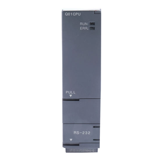
Page 29: Part Names Of Cpu Modules
Flicker: RUN/STOP switch was switched from “STOP“ to “RUN“ after a program or a parameter was written during “STOP“. The CPU is not in “RUN“ mode. MELSEC System Q Beginners Manual 3 – 9... - Page 30 The CPU Modules The MELSEC System Q Procedure to switch a PLC CPU from “STOP“ to “RUN“ after the program or parameters have been changed during “STOP“: Switch the RESET/L.CLR switch to the “RESET“ position. Switch the RUN/STOP switch from “STOP“ to “RUN“.
- Page 31 The CPU Modules System switches Parameters can not be stored in the built-in RAM (Drive 3) (see also chapter 3.4.2). All switches are shipped in the OFF position. RUN/STOP Switch and RESET/L.CLR Switch MELSEC System Q Beginners Manual 3 – 11...
-
Page 32: Memory Organisation
The CPU Modules The MELSEC System Q 3.4.2 Memory Organisation The PLC CPUs uses multiple memories. These memories are identified by their drive number. In addition to the built-in memory high performance CPUs are equipped with a slot for a mem- ory card. - Page 33 – Local devices Local devices are devices exclusively used with the corresponding programs in the pres- MELSEC System Q Beginners Manual 3 – 13...
- Page 34 These data can be stored on ATA memory cards (Q2MEM-8MBA/16MBA/32MBA)only. Memory Cards All PLC CPUs of the MELSEC System Q except the CPU modules Q00JCPU, Q00CPU and Q01CPU can be equipped with a memory card. Before the memory card can be used for the first time the memory card must be formatted by GX Developer or GX IEC Developer.
-
Page 35: Installation Of The Battery For The Cpu Module
The CPU Modules 3.4.3 Installation of the Battery for the CPU Module The PLC CPUs of the MELSEC System Q are equipped with a battery. During interruption of the power supply the battery can hold the data of the program memory, the built-in RAM and the clock for several thousand hours. -
Page 36: Digital Input And Output Modules
Das MELSEC System Q Digital Input and Output Modules Digital Input and Output Modules Input and output modules connect a PLC CPU with the process to be controlled. The digital inputs are used for inputting control signals from the connected switches, buttons or sensors. -
Page 37: Digital Input Modules
Digital Input and Output Modules Das MELSEC System Q 3.5.1 Digital Input Modules Input modules are available for various input voltages: Input module of MELSEC System Q No. of Inputs 0 1 2 3 4 5 6 7 Input voltage 8 9 A B C D E F 5 –... - Page 38 Das MELSEC System Q Digital Input and Output Modules For the MELSEC System Q input modules for DC voltages are available for negative common or for positive common connections. For some modules like the QX71 you can choose between these two connection methods.
- Page 39 , core: 2.8 mm OD max. Internal current consumption 50 mA (all input points ON) (5 V DC) Weight 0.16 kg The response times for OFF -> ON and ON -> OFF can not be set separately. MELSEC System Q Beginners Manual 3 – 19...
- Page 40 Das MELSEC System Q Digital Input and Output Modules Appearance Circuit Diagram Terminal Signal QX80 0 1 2 3 4 5 6 7 8 9 A B C D E F Opto-coupler Internal circuit + – 24 V DC Input module...
- Page 41 Circuit Diagram Terminal Signal QX40 0 1 2 3 4 5 6 7 8 9 A B C D E F Opto-coupler Internal circuit – 24 V DC Input module 24VDC Vacant MELSEC System Q Beginners Manual 3 – 21...
- Page 42 Das MELSEC System Q Digital Input and Output Modules Function of a positive common input module In the preceding diagram, when the push button connected to terminal 1 is closed, the direction of current flow will be as follows: b From the +24 Volt terminal of the external power supply to the Common terminal (termi- nal 17) .
- Page 43 With AC Input type modules, it is recommended that the same supply voltage to the PLC is used as for the inputs (i.e. 100 –120 V AC). This minimises the possibility of an incorrect volt- age being connected to the inputs. MELSEC System Q Beginners Manual 3 – 23...
-
Page 44: Digital Output Modules
Das MELSEC System Q Digital Input and Output Modules 3.5.2 Digital Output Modules The output modules of the MELSEC System Q provide different switching elements for adap- tion to many control tasks: Output module No. of Output outputs type Rated output... - Page 45 External connections 18-point terminal block (M3 x 6 screws) Applicable wire size 0.3 to 0.75 mm , core: 2.8 mm OD max. Internal current consumption 430 mA (5 V DC) Weight 0.22 kg MELSEC System Q Beginners Manual 3 – 25...
- Page 46 Das MELSEC System Q Digital Input and Output Modules Appearance Circuit Diagram Terminal Signal QY10 0 1 2 3 4 5 6 7 8 9 A B C D E F Output module 230 V AC 24VDC 240VAC Vacant Triac Output Modules Digital output modules can switch voltages of 100 to 240 V AC.
- Page 47 Appearance Circuit Diagram Terminal Signal QY22 1 2 3 4 5 6 7 8 9 A B C D E F Output module 100 – 240 V AC 100VAC 240VAC 0.6A Vacant MELSEC System Q Beginners Manual 3 – 27...
- Page 48 Response of the transistor in either direction is only 1 ms at 24 V DC, 200 mA. The exact cur- rent handling capacity of each output is specified in the relevant hardware manual. For the MELSEC System Q transistor output modules are available in sink and source configuration.
- Page 49 Appearance Circuit Diagram Terminal Signal QY80 0 1 2 3 4 5 6 7 8 9 A B C D E F FUSE – 12 – 24 V DC 12VDC 24VDC 0,5A MELSEC System Q Beginners Manual 3 – 29...
- Page 50 Das MELSEC System Q Digital Input and Output Modules Example for a sink transistor output module Item Specifications Type of module QY40P Number of output points Isolation method Opto-coupler Rated switching voltage 12 to 24 V DC (+20/-15%) Switching voltage range 10.2 to 28.8 V DC...
-
Page 51: Special Function Modules
Criteria for selecting analog modules A wide range of analog modules are available for the MELSEC System Q and you need to choose the correct module for each automation task. The main criteria for selection are as... - Page 52 Das MELSEC System Q Special Function Modules The analog input modules of the MELSEC System Q combine a high resolution (0.333 mV / 1.33 µA) with a high conversion speed (80 µs per channel). All modules provide removable screw terminal blocks.
- Page 53 (digital/analog conversion or D/A conversion). The analog output signals generated by the MELSEC System Q use the standard industrial ranges of 0–10V and 4–20mA. The resolution of 0.333 mV respectively 0.83 µA and the extremly short conversion time of 80 µs per output channel are only two of the many fea-...
-
Page 54: Temperature Control Modules With Pid Algorithm
Das MELSEC System Q Special Function Modules Output channels Selectable output Analog output Analog output range ranges 1 to 5 V Voltage or current -10 to +10 V -10 to +10 V (can be selected for each Q62DA Q64DA 0 to 20 mA... -
Page 55: Positioning Modules
Support for plain ASCII data exchange. A user frame can be defined b PLC programming and monitoring through the serial communication line is supported. MELSEC System Q Beginners Manual 3 – 35... -
Page 56: Basic Programmable Interface Modules
Das MELSEC System Q Special Function Modules 3.6.6 BASIC Programmable Interface Modules The modules QD51S-R24 and QD51 work through their own program (written in BASIC) inde- pendently of the Q CPU. Thus, data can be processed and communications can be performed with peripheral devices without imposing an additional load on the PLC CPU. -
Page 57: Networks And Network Modules
Ethernet. Ethernet accepts not only a wide variety of computers such as Windows and UNIX type personal com- puters but also various Factory Automation equipment. The MELSEC System Q has functions which make the best use of the Ethernet features. -
Page 58: Open Networks
MELSEC PLC series. TCP/IP provides logical point-to-point links between two ETHERNET stations. Using the TCP/IP protocol a process supervision system can request up to 960 data words per query if the MELSEC System Q module is used. 3 – 38 MITSUBISHI ELECTRIC... - Page 59 To help reduce costs PROFIBUS/DP uses RS 485 technology with shielded 2-wire cabling. CC-Link The open fieldbus and control network CC-Link provides a fast data communications with dif- ferent devices. The following components from MITSUBISHI ELECTRIC among others can be integrated: b MELSEC PLC systems...
-
Page 60: Melsec Networks
Das MELSEC System Q Networks and Network Modules 3.7.3 MELSEC Networks Command Level TCP/IP ETHERNET MA C E90 0 ° TC P/ IP ET H ER N ET TC P/ IP ET H ER N ET Control Level CC-Link MELSECNET/10... -
Page 61: Network Modules
GX IEC Developer on a personal computer via ETHERNET. MELSECNET Modules The modules QJ71BR11 and QJ71LP21 are used to connect the MELSEC System Q to a MELSECNET/10 or MELSECNET/H network. This enables fast and effective communications between PLCs of the Q, QnA and QnAS series. - Page 62 Supported functions include SYNC, FREEZE, and specialized diag- nostic messages for the specific slave types used. BUS TERMI NATION PROFI BUS I/F b Data exchange with automatic refresh is supported. Batch transfer can be chosen as an option. 3 – 42 MITSUBISHI ELECTRIC...
- Page 63 U ASI PRG ENA. S ERR. ERR. b Highly efficient error securing system COD E 8 .8 . b Automatic data exchange with the PLC MOD E ASI+ ASI- ASI+ ASI- (FG) QJ71AS92 MELSEC System Q Beginners Manual 3 – 43...
- Page 64 Sending and receiving data via mail or FTP b Integration of a self-designed web site and Java applets is possible b Standard connection via ETHERNET to exchange data between other PLCs or PCs b Events and CPU data logging functions 3 – 44 MITSUBISHI ELECTRIC...
-
Page 65: An Introduction To Programming
The specific device is identified by its address. For example, since every controller has multiple inputs you need to specify both the device name and the address in order to read a specific input. MELSEC System Q Beginners Manual 4 – 1... -
Page 66: Bits, Bytes And Words
The next larger information units are the “byte”, which consists of 8 bits, and the “word”, which consists of two bytes. In the MELSEC System Q range of PLCs the data registers are “word devices”, which means that they can store 16-bit values. - Page 67 This is why hexadecimal numbers are used so often in digital tech- nology and programmable logic controllers. In the PLCs of the MELSEC System Q hexadeci- mal numbers are used for the numbering of inputs and outputs and the representation of con- stants.
- Page 68 Octal numbers are listed here for the sake of completeness only. They are not used in a PLC of the MELSEC System Q. In the octal system the digits 8 and 9 don`t exist. Here, the current digit is reset to 0 and the digit in the next position is incremented after the count reaches 7 (0 – 7, 10 –...
-
Page 69: Codes
Example Decimal In the MELSEC System Q the BCD code is not used for internal operations. However, in indus- trial applications BCD is frequently used to input values or to display numbers on a LED dis- play. For those cases several instructions for converting to and from BCD code are available. -
Page 70: Ascii Code
Bits 6 to 4 Bits 3 to 0 0000 0001 0010 0011 0100 0101 0110 & ‘ 0111 1000 1001 1010 1011 1100 < 1101 1110 > 1111 Examples ASCII Hexadecimal „3“ Character ASCII Hexadecimal „G“ Character 4 – 6 MITSUBISHI ELECTRIC... -
Page 71: Programming Languages
If they program carefully and think about the way of working by PLC, they will be glad with this editor. The Structured Text editor is compatible to the IEC 61131-3, all requirements are fulfilled. MELSEC System Q Beginners Manual 4 – 7... -
Page 72: Graphic Editors
To control the program flow, ENO outputs and EN inputs can be connected. In the following example the execution of the second instruction depends on the result of the first instruction. 4 – 8 MITSUBISHI ELECTRIC... - Page 73 Only one step in the sequence can be active at any one time. The next step is not activated before the previous step has been completed and the transition is satisfied. MELSEC System Q Beginners Manual 4 – 9...
-
Page 74: The Iec 61131-3 Standard
Body In the Header the variables which are used in this POU are declared. The Body is the part of the project where the program is edited.Several languages are avail- able for editing a program. 4 – 10 MITSUBISHI ELECTRIC... -
Page 75: Variables
Each variable has the following elements: b Class b Identifier, the name of the variable b Absolute address (optional for global variables) b Data type b Inital value (is specified automatically) b Comment (optional) MELSEC System Q Beginners Manual 4 – 11... - Page 76 0 to 65535 16 Bits DWORD Bit string 32 0 to 4.294.967.295 REAL Floating point value 3.4E +/-38 (7 digits) 32 Bits TIME Time value -T#24d0h31m23s64800ms to T#24d20h31m23s64700ms STRING Character string Character strings are limited to16 characters 4 – 12 MITSUBISHI ELECTRIC...
-
Page 77: The Basic Instruction Set
The Basic Instruction Set The Basic Instruction Set The instructions of the PLCs of the MELSEC System Q can be divided into two basic catego- ries, basic instructions and applied instructions, which are sometimes referred to as “applica- tion instructions”. -
Page 78: Starting Logic Operations
These two instructions result in the following signal sequence: The condition of the LD instruction (poll for signal state “1”) is true so the result of the operation is also true (“1”) and the output is set. 4 – 14 MITSUBISHI ELECTRIC... - Page 79 An example is shown in chapter 4.9.1. Here safety facilities are used to reset internal devices of the PLC and bring a motor to a stop. But the outputs for the motor are only assigned once in the whole program! MELSEC System Q Beginners Manual 4 – 15...
-
Page 80: Using Switches And Sensors
The illustration below shows two program sequences in which the result is exactly the same, even though different switch types are used: When the switch is operated the output is set (switched on). 24 V X000 Y010 Switch operated 24 V X000 Y010 Switch operated 4 – 16 MITSUBISHI ELECTRIC... -
Page 81: And Operations
Example of an AND instruction Ladder Diagram MELSEC Instruction List AND instruction IEC Instruction List In the example output Y10 is only switched on when inputs X0 and X1 are both on: MELSEC System Q Beginners Manual 4 – 17... -
Page 82: Or Operations
An OR operation is logically the same as the parallel connection of multiple switches in an electrical circuit. As soon as any of the switches is closed current will flow. Current will only stop flowing when all the switches are open. 4 – 18 MITSUBISHI ELECTRIC... - Page 83 Example of an ORI instruction Ladder Diagram MELSEC Instruction List IEC Instruction List ORI instruction In the example output Y10 is switched on when either input X0 is on or input X1 is off: MELSEC System Q Beginners Manual 4 – 19...
-
Page 84: Instructions For Connecting Operation Blocks
ANB instruction connecting both OR operations parallel connection (OR operation) Y017 In this example output Y17 is switched on if input X00 is “1” and input X01 is “0”, or if relay M2 is “0” and relay M10 is “1”. 4 – 20 MITSUBISHI ELECTRIC... - Page 85 (AND operation) In this example output Y17 is switched on if input X00 is “1” and input X01 is “0”, or if relay M2 is “0” and relay M10 is “1”. MELSEC System Q Beginners Manual 4 – 21...
-
Page 86: Pulse-Triggered Execution Of Operations
1 for each package. NOTE Most applied instructions can also be executed by pulse signals. For details see chapter 6. 4 – 22 MITSUBISHI ELECTRIC... - Page 87 Type the input device and press the ENTER key. To enter an variable to the output of the func- tion click on the button in the tool bar and then on the ENO output. MELSEC System Q Beginners Manual 4 – 23...
- Page 88 ANDF, ORP and ORF instructions are identical to those of the LD, AND and OR instructions. This means that you can use pulse-trigger operations in your programs in exactly the same way as the conventional versions. 4 – 24 MITSUBISHI ELECTRIC...
-
Page 89: Setting And Resetting Devices
OUT instruction with SET or RST functionality Program an OUT instruction and enter the device to be set or reset. Double click on the OUT instruction. The Signal configuration window is displayed. MELSEC System Q Beginners Manual 4 – 25... - Page 90 IEC Instruction List alternative If the set and reset instructions for the same device both evaluate to “1” the last operation performed has priority. In this example that is the RST instruction, and so M0 remains off. 4 – 26 MITSUBISHI ELECTRIC...
- Page 91 To display the devices with there identifiers it is necessary to declare them as variables in the Global Variable List. Below the Global Variable List for this program example is shown: For further information about the Global Variable List please refer to chapter 4.6.2. MELSEC System Q Beginners Manual 4 – 27...
-
Page 92: Generating Pulses
In the case of device X1 the falling edge of the signal is the trigger. Relays M0 and M1 are only switched on for the duration of a single program cycle. 4 – 28 MITSUBISHI ELECTRIC... -
Page 93: Inverting The Result Of An Operation
To program an INV instruction in Ladder Diagram within an OUT instruction, please double-click on the OUT instruction to display the Signal Configuration window.Select Negation and confirm with OK (see also chapter 4.7.8) MELSEC System Q Beginners Manual 4 – 29... -
Page 94: Inversion Of Bit Output Device
If the condition of the output device is reset (0), it will be set (1) after inversion. MELSEC Instruction List Ladder Diagram IEC Instruction List FF_MD The above program inverts the output condition of Y10 with the rising edge from input X1: 4 – 30 MITSUBISHI ELECTRIC... -
Page 95: Operation Result Into Pulse Conversion
NO contacts the relay could be reset because the instruction outputs one pulse only, if the series connection result of all contacts changes from 0 to 1. MELSEC System Q Beginners Manual 4 – 31... -
Page 96: Safety First
PLC. This is necessary because only an internal interlock is possible in the program and an error in the PLC could cause both outputs to be activated at the same time. 4 – 32 MITSUBISHI ELECTRIC... - Page 97 +24 V COM Y010 Y011 properly (for example if a motor is really turn- ing). Additional functions would be necessary to check this, for example a speed sensor or a voltage load monitor. MELSEC System Q Beginners Manual 4 – 33...
-
Page 98: Programming Plc Applications
Your task is to choose the right instructions from the many supported by the control- lers of the MELSEC System Q to program a suitable solution for your application. This chapter provides a simple example that demonstrate the development of a PLC applica- tion from the definition of the task to the finished program. -
Page 99: Programming
Creating a new project After the start of GX IEC Developer select New in the Project menu. Choose the appropriate PLC type from the selection. Click on OK to confirm your selection MELSEC System Q Beginners Manual 4 – 35... - Page 100 Select Startup Options . For this example Ladder Diagram is chosen. After confirming with OK the programming can begin. The project display screen with the empty body of the POU MAIN is shown as illustrated on the next page. 4 – 36 MITSUBISHI ELECTRIC...
- Page 101 Assigning the Global Variables NOTE If symbolic identifiers are not to be used in the program but only Mitsubishi addresses, then there is no need to fill out the Global Variable List. However the program will no longer be truly IEC61131-3 compliant.
- Page 102 You can also select New Declaration in the Edit menu. b or just click on the button "Insert before" or "Insert after" in the tool bar. These are the inputs and outputs specified as Global Variables for the project: 4 – 38 MITSUBISHI ELECTRIC...
- Page 103 Move the mouse pointer over the work area and click to fix the drop position on the window. Right click on the question mark to call up the Variables Selection window. Click on Global Variables in the Scope dialogue area. MELSEC System Q Beginners Manual 4 – 39...
- Page 104 How a function is enterd into the ladder program is covered in chapter 4.7.7. Click on the button (output variable) in the tool bar. Then click on the output of the PLS_M function to display the variable prompt field. 4 – 40 MITSUBISHI ELECTRIC...
- Page 105 Click on the bus bar at the left on the ladder diagram and “Click – Drag” across the diagram and release on the contact. Release the left mouse button at this point. Connect all other elements in this network in the same way. MELSEC System Q Beginners Manual 4 – 41...
- Page 106 PLC so that the gate can only be closed when it is not opening and vice versa. NOTE The motor direction interlock must also be complemented by an additional interlock with physical contactors outside the PLC (see wiring diagram in chapter 4.9.3.). 4 – 42 MITSUBISHI ELECTRIC...
- Page 107 (or cannot be switched on) if the connection between the switch and the input is interrupted. NOTE The limit switches must be wired so that they also switch off the motor automatically without support from the PLC (see wiring diagram in chapter 4.9.3). MELSEC System Q Beginners Manual 4 – 43...
- Page 108 Enter SM412 into the Address field of the Variable Selection window. Then click on Define . The illustration on the next page shows the entire Ladder Diagram for the control of the rolling shutter gate. 4 – 44 MITSUBISHI ELECTRIC...
- Page 109 OPEN_GATE and CLOSE_GATE by the safety facilities at the end of the program after the setting of these variables. Because of the execution of the program from top to bottom (see chapter 2.2), reset has a higher priority than set and therefore safety is ensured. MELSEC System Q Beginners Manual 4 – 45...
-
Page 110: The Hardware
+24V Y11 Y12 Y1A Y1B Y1C Y1D Y1E Y1F COM Interlock by contactor Deactivation by limit switches A reference for the names of the electrical equipment and the function is shown on the next page. 4 – 46 MITSUBISHI ELECTRIC... - Page 111 Break contact (NC) Photoelectric barrier X7 is set to “1” when an obstacle is registered Warning lamp — Motor contactor (motor reverse) Reverse = OPEN gate Motor contactor (motor forward) Forward = CLOSE gate MELSEC System Q Beginners Manual 4 – 47...
- Page 112 Programming PLC Applications An Introduction to Programming 4 – 48 MITSUBISHI ELECTRIC...
-
Page 113: Devices In Detail
The identifier for output devices is “Y”. Outputs can be used in logic operation instructions as well as with output instructions. However, it is important to remember that you can never use an output instruction on the same output more than once (see also section 4.7.2). MELSEC System Q Beginners Manual 5 – 1... -
Page 114: External I/O Signals And I/O Numbers
X7 for example, an output Y7 can not exist. (Some special function modules however form exceptions to this rule.) ¼ The maximum input/output numbers vary with the type of CPU. Output module Input module 5 – 2 MITSUBISHI ELECTRIC... -
Page 115: Inputs And Outputs Of The Melsec System Q
Devices in Detail Inputs and Outputs 5.1.2 Inputs and Outputs of the MELSEC System Q The following table provides a general overview of the inputs and outputs of the controllers of the MELSEC System Q. Inputs and Outputs Device I/O in Main and Extension Base Units... -
Page 116: Relays
Poll for signal state “0” (has the relay been reset?) In addition to normal relays the controllers of the MELSEC System Q also have retentive or “latched” relays. The normal unlatched relays are all reset to a signal state of “0” when the PLC power supply is switched off, and this is also their standard state when the controller is switched on. -
Page 117: Special Relays
SM414 Variable clock signal pulse NOTE For an overview of all special relays please refer to the Programming Manual for the A/Q se- ries and the MELSEC System Q, art. no. 87431. MELSEC System Q Beginners Manual 5 – 5... -
Page 118: Timers
The timer of the MELSEC System Q are distinguished between low speed and high speed timer. With the GX IEC Developer the time base for the timer (i. e. the frequency of the clock sig- nal counted by the timer) can be set in the range from 1 ms to 1000 ms in the PLC parameters. - Page 119 5.7.1 for details. Retentive timers In addition to the normal timers described above the controllers of the MELSEC System Q also have retentive timers that retain their current time counter value even if the device controlling them is switched off.
- Page 120 X1 or the PLC’s power. Input X2 resets timer ST0 and switches off its output. Timers of the MELSEC System Q PLC-CPUs Timer types Device Normal Timer...
-
Page 121: Counters
Devices in Detail Counters Counters The programmers of the MELSEC System Q also have internal counters that you can use for programming counting operations. Counters count signal pulses that are applied to their inputs by the program. The counter out- put is switched on when the current counter value reaches the setpoint value defined by the program. - Page 122 . Q00J 512* (C0 to C511) Q02H Number of devices and addresses Q06H Q12H 1024* (C0 to C1023) Q25H Q12PH Q25PH Initial values, the number of counters can be set in the PLC parameters. 5 – 10 MITSUBISHI ELECTRIC...
-
Page 123: Registers
FFFFFFFF (-2,147,483,648 to 2,147,483,647). The controllers of the MELSEC System Q have a large number of instructions for using and manipulating registers. You can write and read values to and from registers, copy the contents of registers, compare them and perform math functions on their contents (see chapter 6). -
Page 124: Special Registers
5.5.2 Special registers Just like the special relays (Chapter 5.2.1) the controllers of the MELSEC System Q also have special registers. The device identifier of these registers is "SD". Often there is also a direct connection between the special relays and special registers. For example, special relay SM51 shows that the voltage of the PLC’s battery is too low, and the contents of special register... -
Page 125: File Registers
Number of devices and addresses Q06H 32767 in each block (R0 to R32766) Q12H When a memory card is used, up to 1 million additional file registers can be stored. Q25H Q12PH Q25PH MELSEC System Q Beginners Manual 5 – 13... -
Page 126: Constants
When characters are designated in the sequence program by quotation marks they are inter- preted as ASCII code (e. g. "MOTOR12"). One character occupies 1 byte. You can use up to 32 characters for a character string. 5 – 14 MITSUBISHI ELECTRIC... -
Page 127: Programming Tips For Timers And Counters
HMI control panel. The listing shown on the next page is an example of how to specify setpoint values indirectly: MELSEC System Q Beginners Manual 5 – 15... - Page 128 Also, remember that even the contents of these registers will also be lost when the PLC is switched off if the backup battery is empty. 5 – 16 MITSUBISHI ELECTRIC...
-
Page 129: Switch-Off Delay
T0 is started when X1 is switched off. At the end of the delay period (300 x 0.1s = 30s in the example) T0 interrupts the Y10 latch and switches the output off. Signal sequence 30 s MELSEC System Q Beginners Manual 5 – 17... - Page 130 When X1 is switched on output Y10 is set (switched on). When X1 is switched off timer T0 is started. After the delay period T0 then resets output Y10. The resulting signal sequence is identical with that produced by program version 1. 5 – 18 MITSUBISHI ELECTRIC...
-
Page 131: Delayed Make And Break
But even when X0 is switched off und T1 is reset Y10 remains on because of the latching func- tion. When X1 is switched off timer T2 is started. After the delay period t2 the output Y10 is reset. MELSEC System Q Beginners Manual 5 – 19... -
Page 132: Clock Signal Generators
1-second intervals, for example. For full details on all special relays see the Pro- gramming Manual for the A/Q series and the MELSEC System Q, Art. no. 87431. If you need a different clock frequency or different on and off times you can program your own... -
Page 133: More Advanced Programming
The following table shows all the applied instructions currently supported by the MELSEC System Q family of controllers. This list may look a little overwhelming at first, but don’t worry – you don’t have to memorise them all! When you are programming you can use the powerful Help functions of GX Developer and GX IEC Developer to find the instructions you need. - Page 134 ORE< ORE<> ORE<= ORE>= LD$= LD$> LD$< LD$<> LD$<= LD$>= AND$= Character string data Compare of two character strings (one character at a AND$> comparisons time) within operations AND$< AND$<> AND$>= AND$<= OR$= OR$> OR$< 6 – 2 MITSUBISHI ELECTRIC...
- Page 135 DINT Converts a floating decimal point value to 32-bit binary Converts 16-bit binary data to 32-bit binary data Binary data -> Binary data Converts 32-bit binary data to 16-bit binary data WORD MELSEC System Q Beginners Manual 6 – 3...
- Page 136 Combination of two 32-bit devices (XOR) Combination of 16-bit devices in data blocks BKXOR WNXR Combination of two 16-bit devices Logical exklusive DNXR Combination of two 32-bit devices NOR (XNR) Combination of 16-bit devices in data blocks BKXNR 6 – 4 MITSUBISHI ELECTRIC...
- Page 137 Calculation of totals DWSUM Calculate totals of 32-bit binary data blocks Start of a program repetition Structured program Repetition instructions End of a program repetition NEXT instructions BREAK Terminate the FOR/NEXT loop MELSEC System Q Beginners Manual 6 – 5...
- Page 138 Convert decimal ASCII into 16-/32-bit binary data Binary DDABIN HABIN Hexadecimal (ASCII) Convert decimal ASCII into 16-/32-bit binary data -> Binary DHABIN It is not possible to program the instructions FCALL, ECALL and EFCALL with the GX IEC Developer. 6 – 6 MITSUBISHI ELECTRIC...
- Page 139 Limitation of output values for 16-/32-bit binary data DLIMIT BAND Data control Dead band control Dead band control of 16-/32-bit binary data instructions DBAND ZONE Zone control Zone control of 16-/32-bit binary data DZONE MELSEC System Q Beginners Manual 6 – 7...
- Page 140 Pulse output PLSY Pulse output with adjustable number of pulses Puls width modulation Pulse output with adjustable cycle time and ON time Input matrix Building of an input matrix for reading of information 6 – 8 MITSUBISHI ELECTRIC...
- Page 141 Write data gent device station. Write data from the PLC CPU to the automatic updating RITO buffer memory of the CC-Link master. Afterwards the data will be send to the specified station. MELSEC System Q Beginners Manual 6 – 9...
-
Page 142: Additional Instructions For Process Cpus
In manual mode the manipulated value is output. Provides a bump-less transfer when switching from man- Bump-less transfer BUMP ual to automatic mode. Analog memory Increases or decreases the output value at a fixed rate. 6 – 10 MITSUBISHI ELECTRIC... - Page 143 Automatic determination of the PID constants for a PID Autotuning PID constants control with the instructions PID or 2PID NOTE For more information about PID control instructions please refer to the programming manual for the QnPHCPUs, Art. no. 149256. MELSEC System Q Beginners Manual 6 – 11...
-
Page 144: Instructions For Moving Data
If you add a “P” to the MOV instruction (MOVP) it will only be executed once, on the rising edge of the signal pulse generated by the input condition. 6 – 12 MITSUBISHI ELECTRIC... - Page 145 32-bit devices as input and output variables directly. These devices must be declared as Global Variables (see chapter 4.6.2). In this example the identifiers var_D0 and var_D40 were chosen to point to this fact. MELSEC System Q Beginners Manual 6 – 13...
-
Page 146: Moving Groups Of Bit Devices
M0 – M3 to outputs Y10 – Y13: If the destination range is smaller than the source range the excess bits are simply ignored (see the following illustration, top example). If the destination is larger than the source “0” is 6 – 14 MITSUBISHI ELECTRIC... - Page 147 Sign bit (0: positive, 1: negative) MOV D0 -> K2M0 These relays will not be changed M14 M13 M12 M11 M10 MOV K2M0 -> D1 Sign bit (0: positive, 1: negative) Bit 15 Bit 0 MELSEC System Q Beginners Manual 6 – 15...
-
Page 148: Moving Blocks Of Data With The Bmov Instruction
Example – Data source: K1M0 – Data destination: K1Y0 – Number of elements to be moved: 2 Y000 Y001 Y002 Y003 This copies 2 blocks with 4 bit devices each. Y004 Y005 Y006 Y007 6 – 16 MITSUBISHI ELECTRIC... -
Page 149: Copying Source Devices To Multiple Destinations (Fmov)
D 10 D 11 D 12 D 13 7 data words D 14 D 15 D 16 Here too, FMOV has a pulse-triggered version, FMOVP (see section 6.2.1 for details on pulse-triggered execution). MELSEC System Q Beginners Manual 6 – 17... -
Page 150: Exchanging Data With Special Function Modules
The number of buffer memory cells to be read from or written to – The location in the PLC CPU where the data from the module is to be stored or containing the data to be written to the module 6 – 18 MITSUBISHI ELECTRIC... - Page 151 Pulse-triggered execution of the instructions If you add a P suffix to the instructions the data transfer is initiated by pulse trigger (for details see the description of the MOV instruction in section 6.2.1). MELSEC System Q Beginners Manual 6 – 19...
- Page 152 ¿ Number of data units to be transferred In the example above the contents of data register D3 is copied to the buffer address 32 of the special function module with the head address 1 (X/Y010). 6 – 20 MITSUBISHI ELECTRIC...
- Page 153 In GX Configurator-AD can also be specified where in the PLC CPU for instance measured val- ues should be stored. Afterwards this data transfer is processed automatically. FROM-/TO instructions or the above described direct access to the buffer memory are not required. MELSEC System Q Beginners Manual 6 – 21...
-
Page 154: Compare Instructions
To achieve this an output instruction or an logical operation can be made conditional on the result of a compare instruction. In addition to the compare instructions described here the PLC CPUs of the MELSEC System Q can compare also floating decimal point values, binary block data and character strings. - Page 155 MELSEC Instruction List LD> K-2500 IEC Instruction List TRUE LD_GT_M D10, -2500 TC52 Output Y13 is switched on when the contents of D10 is greater than -2,500 and timer T52 has finished running. MELSEC System Q Beginners Manual 6 – 23...
- Page 156 An OR comparison can be used just like a normal OR instruction (see chapter 4). In this exam- ple the output Y1B is set when the input X7 is on or the Counter C20 has reached the actual value "200". 6 – 24 MITSUBISHI ELECTRIC...
-
Page 157: Math Instructions
Math Instructions Math Instructions All the controllers of the MELSEC System Q can perform all four basic arithmetical operations and can add, subtract, multiply and divide. MELSEC instructions are available for math opera- tions with binary values, binary block data, BCD values and character strings. - Page 158 FMOV_M D 11 D 12 D 13 D 11 32700 MOV_M 32700 D 13 MOV_M D 11 D 13 D 15 32700 32800 ADD_E Double word register D14 contains the correct result of the addition. 6 – 26 MITSUBISHI ELECTRIC...
- Page 159 Release the left mouse button at this point When programming in IEC instruction list just enter the ADD instruction several times. For example: MELSEC System Q Beginners Manual 6 – 27...
-
Page 160: Subtraction
If you want you can also write the result to one of the source devices. However, if you do this remember that the result will then change in every program cycle if the SUB instruction is exe- cuted cyclically! 6 – 28 MITSUBISHI ELECTRIC... -
Page 161: Multiplication
2448 The signs of the values are taken into account by the MUL instruction. In this example the value in D10 is multiplied by the constant value -5: D 10 D 20 MELSEC System Q Beginners Manual 6 – 29... -
Page 162: Division
Remainder (40 - 36 = 4) (Output of MOD instruction) The signs of the values are taken into account by the DIV instruction. In this example the coun- ter value of C0 is divided by the value in D10: D 10 D 200 Ö 6 – 30 MITSUBISHI ELECTRIC... -
Page 163: Combining Math Instructions
The following example shows how you could calculate the sum of the values in data registers D101 and D102, then multiply the result by the factor 4 and finally divide the product by 9. The result of this calculation is stored in data register D103. Ladder Diagram MELSEC System Q Beginners Manual 6 – 31... - Page 164 Math Instructions More Advanced Programming 6 – 32 MITSUBISHI ELECTRIC...
-
Page 165: Index
PLC CPUs · · · · · · · · · · · · · · · · · · 3-8 RUN/STOP switch · · · · · · · · · · · · · 3-11 System switches · · · · · · · · · · · · · · 3-11 MELSEC System Q Beginners Manual... - Page 166 LDI · · · · · · · · · · · · · · · · · · · · · 4-14 Motion CPUs · · · · · · · · · · · · · · · · · · 3-7 MITSUBISHI ELECTRIC...
- Page 167 Program instruction · · · · · · · · · · · · · · · 4-1 Special function modules Proximity sensors · · · · · · · · · · · · · · · 3-19 Data exchange with PLC CPU· · · · · · · 6-18 MELSEC System Q Beginners Manual...
- Page 168 TO instruction · · · · · · · · · · · · · · · · · 6-20 Transistor output modules· · · · · · · · · · · 3-28 Triac output modules · · · · · · · · · · · · · 3-27 MITSUBISHI ELECTRIC...
- Page 170 MITSUBISHI ELECTRIC MITSUBISHI ELECTRIC INDUSTRIAL AUTOMATION Gothaer Straße 8 Telefon: 02102 486-0 Fax: 02102 486-7170 www.mitsubishi-automation.de D-40880 Ratingen Hotline: 01805 000-7650 megfa-mail@meg.mee.com www.mitsubishi-automation.com...