Sign In
Upload
Manuals
Brands
Olympus Manuals
Test Equipment
OmniScan MX
Olympus OmniScan MX Manuals
Manuals and User Guides for Olympus OmniScan MX. We have
2
Olympus OmniScan MX manuals available for free PDF download: User Manual
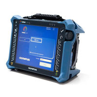
Olympus OmniScan MX User Manual (228 pages)
Brand:
Olympus
| Category:
Test Equipment
| Size: 3.31 MB
Table of Contents
Table of Contents
3
DMTA-20015-01EN [U8778402], Rev. J, January
10
List of Abbreviations
11
Figure I-1 the Omniscan MX2
13
Labels and Symbols
13
Figure I-2 the Omniscan MX
14
Figure I-3 Module Identification Label
14
Table 1 Omniscan MX2 and the Omniscan MX Rating Labels
15
Table 2 Content of the Omniscan MX2 Identification Label
17
Table 3 Content of a Module Identification Label
17
Figure I-4 the Omniscan MX2 Membrane Vent
18
Important Information - Please Read before Use
19
Intended Use
19
Instruction Manual
19
Instrument Compatibility
20
Repair and Modification
20
Safety Symbols
21
Safety Signal Words
21
Note Signal Words
22
Safety
22
Warnings
23
Battery Precautions
24
Equipment Disposal
25
CE (European Community)
25
WEEE Directive
25
China Rohs
26
EMC Directive Compliance
26
FCC (USA) Compliance
26
ICES-001 (Canada) Compliance
27
Warranty Information
27
Technical Support
28
Omniscan MX2
29
Introduction
31
DMTA-20015-01EN [U8778402], Rev. J, January
32
1 Overview of the Equipment
33
Front Panel of the Omniscan MX2
33
Display Touch Screen
34
Figure 1-1 Front Panel of the Omniscan MX2
34
Main Control Area
34
Increment Keys
35
Power Key
35
Table 4 Main Control Area
35
Help Key
36
Indicator Lights
36
Power Indicator Light
36
Table 5 Power Indicator Light Statuses
36
Acquisition Indicator Light
37
Alarm Indicator Lights
37
Table 6 Acquisition Indicator Light Statuses
37
Right Side Panel
38
Figure 1-2 Right Side Panel of the Omniscan MX2
38
Left Side Panel
39
Figure 1-3 Left Side Panel of the Omniscan MX2
39
Top Panel
40
Figure 1-4 Top Panel of the Omniscan MX2
40
Rear Panel
41
2 Basic Operation
43
Turning on and off the Omniscan MX2
43
Figure 2-1 the Shut down Button
44
Figure 2-2 Saving the Setup
44
Sleep Mode
45
Automatic Start-Up Mode
45
Figure 2-3 Sleep Mode Selection
45
Power Supply Management
46
DC Power Adaptor
46
Figure 2-4 the Omniscan MX2 DC Power Adaptor Plug
47
Lithium-Ion Batteries
47
Battery Status Indicators
48
Figure 2-5 Battery Charge Status: Charge Remaining in both Batteries
48
Table 7 Battery Status Indicator Variations
49
Battery Charging
50
Battery Removal and Installation
50
Figure 2-6 Removing a Lithium-Ion Battery
50
Maximizing the Performance of Lithium-Ion Batteries
51
Used Battery Disposal
52
Warnings on Battery Use
53
Peripheral Connection
53
Figure 2-7 Attaching a Ferrite Clamp Filter to a Cable (Example Shown with the Scanner Interface Cable)
55
Figure 2-8 Omniscan MX2 Connection Diagram - Ferrite Clamp Filters
56
Table 8 Ferrite Clamp Filter Locations
56
Omniscan MX2 Software Installation
57
3 Maintenance
59
Preventative Maintenance
59
Instrument Cleaning
59
Casing and Acquisition Module Cleaning
59
Figure 3-1 Module with PA Connector Cap
61
Screen and Screen Protector Cleaning
61
Screen and Screen Protector Cleaning
62
Replacing the Touch-Screen Protector
62
4 Troubleshooting
63
Start-Up Problems
63
Message
63
Battery Charging Problems
64
Battery Life Problems
64
Table 9 Message
64
DMTA-20015-01EN [U8778402], Rev. J, January
64
5 Specifications
67
Table 10 Omniscan MX2 General Specifications
67
Table 11 Omniscan MX2 Alarms
71
6 Connector References
73
Serial Connector
74
Figure 6-1 the Serial Connector
74
Table 12 Pinout for the Serial Connector
74
Scanner Interface Connector
75
Figure 6-2 the Scanner Interface LEMO Connector (Contact View)
75
Table 13 Pinout for the Scanner Interface LEMO Connector
76
Scanner Interface Adaptor
78
Figure 6-3 the Scanner Interface Adaptor LEMO Connector (Solder-Cup View)
78
Figure 6-4 the Scanner Interface Adaptor DE-15 Connector (Solder-Cup View)
79
Alarm and I/O Connector
80
Figure 6-5 the Alarm and I/O Connector
80
Table 14 Scanner Interface Adaptor Pinout [DE-15 to LEMO]
80
Table 15 Pinout for the Alarm and I/O Connector
81
Omniscan MX
83
Introduction
85
Omniscan MX Features
85
7 Overview of the Equipment
87
Front Panel of the Omniscan MX
87
Figure 7-1 Front Panel of the Omniscan MX
88
Main Control Area
88
Function Keys
89
Table 16 Main Control Area
89
Figure 7-2 Information Provided on each Key
90
Power Key
90
Help Key
91
Menu Key
91
Submenu Keys
91
Up and down Keys
91
Indicator Lights
92
Keypad Indicator Light
92
Parameter Keys
92
Power Indicator Light
92
Table 17 Keypad Indicator Light Statuses
92
Acquisition Indicator Light
93
Table 18 Power Indicator Light Statuses
93
Table 19 Acquisition Indicator Light Statuses
93
Alarm Indicator Lights
94
Right Side Panel
94
Figure 7-3 Right Side Panel of the Omniscan MX
95
Left Side Panel
96
Figure 7-4 Left Side Panel of the Omniscan MX
96
Top Panel
97
Rear Panel
97
Figure 7-5 Top Panel of the Omniscan MX
97
8 Basic Operation
99
Turning on and off the Omniscan MX
99
Power Supply Management
100
DC Power Adaptor
100
DMTA-20015-01EN [U8778402], Rev. J, January
101
Figure 8-1 the Omniscan MX DC Power Adaptor Plug
101
Lithium-Ion Batteries
101
Battery Status Indicators
102
Figure 8-2 Battery Charge Status: Charge Remaining in both Batteries
102
Battery Removal and Installation
103
Table 20 Battery Status Indicator Variations
103
Battery Charging
104
Figure 8-3 Removing the Lithium-Ion Battery
104
Maximizing the Performance of Lithium-Ion Batteries
105
Used Battery Disposal
106
Warnings on Battery Use
106
Peripheral Connection
107
Figure 8-4 Attaching a Ferrite Clamp Filter to a Cable (Example Shown with the 4CH/MUX Cable)
109
Omniscan Software Installation
110
Figure 8-5 the Omniscan MX Connection Diagram Indicating Where to Attach Ferrite Clamp Filters
110
9 Maintenance
113
Preventative Maintenance
113
Instrument Cleaning
113
Casing and Acquisition Module Cleaning
113
LCD Screen Protector Cleaning
114
10 Troubleshooting
115
10.1 Start-Up Problems
115
10.2 Messages
115
10.3 Battery Charging Problems
116
10.4 Battery Life Problems
116
Table 21 Messages
116
10.5 Memory Card Problems
117
10.6 Headphone or Speaker Problems
118
Headphones or External Speakers
118
Internal Speaker
118
10.7 Video Input Problems
118
10.8 Video Output Problems
119
10.9 Networking Problems
119
10.10 USB Peripheral Problems
119
10.11 Boot Problems
120
10.11.1 A-Scan Display
120
10.11.2 Omniscan MX Start-Up
121
11 Specifications
123
Table 22 Omniscan MX General Specifications
123
Table 23 Omniscan MX Alarms
125
12 Connector References
127
Serial Connector
128
Figure 12-1 the Serial Connector
128
Table 24 Pinout for the Serial Connector
128
12.2 Scanner Interface Connector
129
Figure 12-2 the Scanner Interface Connector
129
Table 25 Pinout for the Scanner Interface Connector
129
12.3 Alarm and I/O Connector
132
Figure 12-3 the Alarm and I/O Connector
132
Table 26 Pinout for the Alarm and I/O Connector
132
DMTA-20015-01EN [U8778402], Rev. J, January
133
Appendix A: Compatibility Tables
135
Table 27 Module Compatibility
135
Table 28 Omniscan MX2 Software Compatibility
136
Table 29 Omniscan MX Software Compatibility
136
Table 31 New Accessories Compatibility
137
Table 30 Old Accessory Compatibility
137
Appendix B: Acquisition Module Description and Replacement Procedures
139
General Specifications
139
Table 32 General Specifications for All Modules
140
Table 33 General Specifications - OMNI-M2-PA1664/16128
140
Table 34 General Specifications - OMNI-M2-UT-2C
141
Connectors
142
Figure B-1 BNC, LEMO, and Phased Array Probe Connectors
142
B.2 Connectors
142
Replacement Procedure
143
B.3 Replacement Procedure
143
Fan Filter Cleaning Procedure
144
Figure B-2 the Phased Array Module Connector Guide Location
144
Figure B-3 the Grill and Filter of the OMNI-M-Pa32Nn Model
145
Appendix C: OMNI-M-PA32128 Module Specifications
147
Figure C-1 Phased Array Module Model OMNI-M-PA32128
147
Acoustic Specifications
148
C.1 Acoustic Specifications
148
Table 35 Acoustic Specifications
148
Acquisition Specifications
149
C.2 Acquisition Specifications
149
Data Specifications
149
Table 36 Acquisition Specifications
149
Table 37 Data Specifications
149
Appendix D: OMNI-M-UT-2C, OMNI-M-UT-4C, and OMNI-M-UT-8C Module Specifications
151
Figure D-1 Modules OMNI-M-UT-2C (Left) and OMNI-M-UT-8C (Right)
151
Acoustic Specifications
152
D.1 Acoustic Specifications
152
Table 38 Acoustic Specifications
152
Acquisition Specifications
153
D.2 Acquisition Specifications
153
Data Specifications
153
Table 39 Acquisition Specifications
153
Table 40 Data Specifications
153
Appendix E: OMNI-M-PA1616M and OMNI-M-PA1664M Module Specifications
155
Acoustic Specifications
156
Figure E-1 Phased Array Module Models OMNI-M-PA1616M and
156
Table 41 Acoustic Specifications
156
E.1 Acoustic Specifications
156
Acquisition Specifications
157
Table 42 Acquisition Specifications
157
E.2 Acquisition Specifications
157
Data Specifications
158
Table 43 Data Specifications
158
E.3 Data Specifications
158
Appendix F: OMNI-M-PA1616 Module Specifications
159
Acoustic Specifications
160
Figure F-1 Phased Array Module Model OMNI-M-PA1616
160
Table 44 Acoustic Specifications
160
F.1 Acoustic Specifications
160
Acquisition Specifications
161
Table 45 Acquisition Specifications
161
F.2 Acquisition Specifications
161
Data Specifications
162
Table 46 Data Specifications
162
F.3 Data Specifications
162
Appendix G: OMNI-M-PA16128 Module Specifications
163
Figure G-1 Phased Array Module Model OMNI-M-PA16128
163
Acoustic Specifications
164
G.1 Acoustic Specifications
164
Table 47 Acoustic Specifications
164
Acquisition Specifications
165
Data Specifications
165
G.2 Acquisition Specifications
165
Table 48 Acquisition Specifications
165
Table 49 Data Specifications
165
Appendix H: OMNI-M-PA16128PR Module Specifications
167
Acoustic Specifications
168
Figure H-1 Phased Array Module Model OMNI-M-PA16128PR
168
Table 50 Acoustic Specifications
168
H.1 Acoustic Specifications
168
Acquisition Specifications
169
Table 51 Acquisition Specifications
169
H.2 Acquisition Specifications
169
Data Specifications
170
Table 52 Data Specifications
170
H.3 Data Specifications
170
Appendix I: OMNI-M-PA32128PR Module Specifications
171
Figure I-1 Phased Array Module Model OMNI-M-PA32128PR
171
DMTA-20015-01EN [U8778402], Rev. J, January
171
Acoustic Specifications
172
I.1 Acoustic Specifications
172
Table 53 Acoustic Specifications
172
Acquisition Specifications
173
Data Specifications
173
I.2 Acquisition Specifications
173
Table 54 Acquisition Specifications
173
Table 55 Data Specifications
173
Appendix J: OMNI-M-PA3232 Module Specifications
175
Figure J-1 Phased Array Module Model OMNI-M-PA3232
175
Acoustic Specifications
176
J.1 Acoustic Specifications
176
Table 56 Acoustic Specifications
176
Acquisition Specifications
177
Data Specifications
177
J.2 Acquisition Specifications
177
Table 57 Acquisition Specifications
177
Table 58 Data Specifications
177
Appendix K: OMNI-M-PA1664 Module Specifications
179
Acoustic Specifications
180
Figure K-1 Phased Array Module Model OMNI-M-PA1664
180
Table 59 Acoustic Specifications
180
K.1 Acoustic Specifications
180
Acquisition Specifications
181
Table 60 Acquisition Specifications
181
K.2 Acquisition Specifications
181
Data Specifications
182
Table 61 Data Specifications
182
K.3 Data Specifications
182
Appendix L: OMNI-M-ECT4 Module Specifications
183
ECT Acquisition Module Description
183
ECT Acquisition Module Receptacles
183
Probe Connectors
184
Figure L-1 the ECT Module with the 1CH and 4CH Connectors
184
Figure L-2 the 4CH, 19-Pin Eddy Current Probe Connector
184
L.3 Probe Connectors
184
4CH Connector References
185
Figure L-3 the 1CH, BNC Eddy Current Probe Connector
185
Figure L-4 the 4CH Connector
185
Table 62 Pinout for the
185
ECT Acquisition Module Specifications
186
General Specifications
187
Generator and Receiver
187
L.5.1 General Specifications
187
Table 63 General Specifications
187
Table 64 Generator and Receiver Specifications
187
Data
188
L.5.3 Data
188
Table 65 Data
188
Appendix M: OMNI-M-ECA4-32 Module Specifications
189
ECA Acquisition Module Description
189
ECA Acquisition Module Receptacles
190
Figure M-1 the OMNI-M-ECA4-32 Acquisition Module
190
Probe Connectors
191
Figure M-2 the ECA Module with Connectors
191
Figure M-3 the Olympus ECA Probe Connector
192
Figure M-4 the 19-Pin Eddy Current Probe Connector
192
Figure M-5 an Eddy Current Probe BNC Connector
192
4CH Connector References
193
Figure M-6 the
193
Table 66 Pinout for the
193
ECA Acquisition Module Specifications
194
General Specifications
194
Table 67 General Specifications
194
Generator and Receiver
195
Table 68 Generator and Receiver Specifications
195
Data
196
M.5.3 Data
196
Table 69 Data Specifications
196
Appendix N: OMNI-M2-PA1664/16128/32128/32128PR Module Specifications
197
Figure N-1 Module Side View
197
Figure N-2 Phased Array Module Model OMNI-M2-PA1664/16128/32128/32128PR
198
Figure N-3 Module with Anchor Base
198
Figure N-4 Module with PA Connector Cap
199
Acoustic Specifications
200
Figure N-5 Fastening Hole Location and Specifications
200
N.1 Acoustic Specifications
200
Table 70 Acoustic Specifications - UT Channel Using UT Connector
200
Table 71 Acoustic Specifications - PA Channel
201
Acquisition Specifications
202
N.2 Acquisition Specifications
202
Table 72 Acquisition Specifications
202
Data Specifications
203
N.3 Data Specifications
203
Table 73 Data Specifications
203
Appendix O: OMNI-M2-UT-2C Module Specifications
205
Figure O-1 Module Side View
205
Figure O-2 Module Model OMNI-M2-UT-2C
206
Figure O-3 Fastening Hole Location and Specifications
206
Acoustic Specifications
207
O.1 Acoustic Specifications
207
Table 74 Acoustic Specifications
207
Acquisition Specifications
208
Data Specifications
208
O.2 Acquisition Specifications
208
Table 75 Acquisition Specifications
208
Table 76 Data Specifications
208
List of Figures
211
List of Tables
213
Index
217
Advertisement
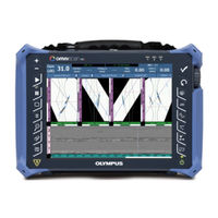
Olympus OmniScan MX User Manual (230 pages)
Multitechnology Flaw Detector
Brand:
Olympus
| Category:
Measuring Instruments
| Size: 3.6 MB
Table of Contents
Table of Contents
3
DMTA-20015-01EN [U8778402], Rev. M, February
10
List of Abbreviations
11
Abbreviations
11
Figure I-1 the Omniscan MX2
13
Labels and Symbols
13
Figure I-2 the Omniscan MX
14
Figure I-3 Module Identification Label
14
Table 1 Omniscan MX2 and the Omniscan MX Rating Labels
16
Table 2 Content of the Omniscan MX2 Identification Label
17
Table 3 Content of a Module Identification Label
18
Figure I-4 the Omniscan MX2 Membrane Vent
19
Important Information - Please Read before Use
21
Intended Use
21
Instruction Manual
21
Instrument Compatibility
22
Repair and Modification
22
Safety Symbols
23
Safety Signal Words
23
Note Signal Words
24
Safety
24
Warnings
25
Battery Precautions
26
Equipment Disposal
27
CE (European Community)
27
WEEE Directive
28
China Rohs
28
Korea Communications Commission (KCC)
29
EMC Directive Compliance
29
FCC (USA) Compliance
29
ICES-001 (Canada) Compliance
30
Warranty Information
30
Technical Support
31
Omniscan MX2
33
DMTA-20015-01EN [U8778402], Rev. M, February
35
Introduction
35
1 Overview of the Equipment
37
Front Panel of the Omniscan MX2
37
Display Touch Screen
38
Figure 1-1 Front Panel of the Omniscan MX2
38
Main Control Area
38
Increment Keys
39
Power Key
39
Table 4 Main Control Area
39
Help Key
40
Indicator Lights
40
Power Indicator Light
40
Table 5 Power Indicator Light Statuses
40
Acquisition Indicator Light
41
Alarm Indicator Lights
41
Table 6 Acquisition Indicator Light Statuses
41
Right Side Panel
42
Figure 1-2 Right Side Panel of the Omniscan MX2
42
Left Side Panel
43
Figure 1-3 Left Side Panel of the Omniscan MX2
43
Top Panel
44
Figure 1-4 Top Panel of the Omniscan MX2
44
Rear Panel
45
2 Basic Operation
47
Turning on and off the Omniscan MX2
47
Figure 2-1 the Shut down Button
48
Figure 2-2 Saving the Setup
48
Automatic Start-Up Mode
49
Power Supply Management
49
DC Power Adaptor
50
Figure 2-3 the Omniscan MX2 DC Power Adaptor Plug
50
Battery Status Indicators
51
Lithium-Ion Batteries
51
Figure 2-4 Battery Charge Status: Charge Remaining in both Batteries
52
Battery Removal and Installation
53
Table 7 Battery Status Indicator Variations
53
Battery Charging
54
Figure 2-5 Removing a Lithium-Ion Battery
54
Maximizing the Performance of Lithium-Ion Batteries
55
Used Battery Disposal
56
Warnings on Battery Use
56
Peripheral Connection
57
Figure 2-6 Attaching a Ferrite Clamp Filter to a Cable (Example Shown with the Scanner Interface Cable)
59
Figure 2-7 Omniscan MX2 Connection Diagram - Ferrite Clamp Filters
60
Table 8 Ferrite Clamp Filter Locations
60
Omniscan MX2 Software Installation
61
3 Maintenance
63
Preventative Maintenance
63
Instrument Cleaning
63
Casing and Acquisition Module Cleaning
63
Figure 3-1 Module with PA Connector Cap
65
Screen and Screen Protector Cleaning
65
Screen and Screen Protector Cleaning
66
Replacing the Touch-Screen Protector
66
4 Troubleshooting
67
Start-Up Problems
67
Message
67
Battery Charging Problems
68
Battery Life Problems
68
Table 9 Message
68
DMTA-20015-01EN [U8778402], Rev. M, February
68
5 Specifications
71
Table 10 Omniscan MX2 General Specifications
71
Table 11 Omniscan MX2 Alarms
75
6 Connector References
77
Serial Connector
78
Figure 6-1 the Serial Connector
78
Table 12 Pinout for the Serial Connector
78
Scanner Interface Connector
79
Figure 6-2 the Scanner Interface LEMO Connector (Contact View)
79
Table 13 Pinout for the Scanner Interface LEMO Connector
80
Alarm and I/O Connector
82
Figure 6-3 the Alarm and I/O Connector
82
Table 14 Pinout for the Alarm and I/O Connector
83
Omniscan MX
85
Introduction
87
Omniscan MX Features
87
7 Overview of the Equipment
89
Front Panel of the Omniscan MX
89
Figure 7-1 Front Panel of the Omniscan MX
90
Main Control Area
90
Function Keys
91
Table 15 Main Control Area
91
Figure 7-2 Information Provided on each Key
92
Power Key
92
Help Key
93
Menu Key
93
Submenu Keys
93
Up and down Keys
93
Indicator Lights
94
Keypad Indicator Light
94
Parameter Keys
94
Power Indicator Light
94
Table 16 Keypad Indicator Light Statuses
94
Acquisition Indicator Light
95
Table 17 Power Indicator Light Statuses
95
Table 18 Acquisition Indicator Light Statuses
95
Alarm Indicator Lights
96
Right Side Panel
96
Figure 7-3 Right Side Panel of the Omniscan MX
97
Left Side Panel
98
Figure 7-4 Left Side Panel of the Omniscan MX
98
Top Panel
99
Rear Panel
99
Figure 7-5 Top Panel of the Omniscan MX
99
8 Basic Operation
101
Turning on and off the Omniscan MX
101
Power Supply Management
102
DC Power Adaptor
102
DMTA-20015-01EN [U8778402], Rev. M, February
103
Figure 8-1 the Omniscan MX DC Power Adaptor Plug
103
Lithium-Ion Batteries
103
Battery Status Indicators
104
Figure 8-2 Battery Charge Status: Charge Remaining in both Batteries
104
Battery Removal and Installation
105
Table 19 Battery Status Indicator Variations
105
Battery Charging
106
Figure 8-3 Removing the Lithium-Ion Battery
106
Maximizing the Performance of Lithium-Ion Batteries
107
Used Battery Disposal
108
Warnings on Battery Use
108
Peripheral Connection
109
Figure 8-4 Attaching a Ferrite Clamp Filter to a Cable (Example Shown with the 4CH/MUX Cable)
111
Omniscan Software Installation
112
Figure 8-5 the Omniscan MX Connection Diagram Indicating Where to Attach Ferrite Clamp Filters
112
9 Maintenance
115
Preventative Maintenance
115
Instrument Cleaning
115
Casing and Acquisition Module Cleaning
115
LCD Screen Protector Cleaning
116
10 Troubleshooting
117
10.1 Start-Up Problems
117
10.2 Messages
117
10.3 Battery Charging Problems
118
10.4 Battery Life Problems
118
Table 20 Messages
118
10.5 Memory Card Problems
119
10.6 Headphone or Speaker Problems
120
Headphones or External Speakers
120
Internal Speaker
120
10.7 Video Input Problems
120
10.8 Video Output Problems
121
10.9 Networking Problems
121
10.10 USB Peripheral Problems
121
10.11 Boot Problems
122
10.11.1 A-Scan Display
122
10.11.2 Omniscan MX Start-Up
123
11 Specifications
125
Table 21 Omniscan MX General Specifications
125
Table 22 Omniscan MX Alarms
127
12 Connector References
129
12.1 Serial Connector
130
Figure 12-1 the Serial Connector
130
Table 23 Pinout for the Serial Connector
130
12.2 Scanner Interface Connector
131
Figure 12-2 the Scanner Interface Connector
131
Table 24 Pinout for the Scanner Interface Connector
131
12.3 Alarm and I/O Connector
134
Figure 12-3 the Alarm and I/O Connector
134
Table 25 Pinout for the Alarm and I/O Connector
134
Appendix A: Compatibility Tables
137
Table 26 Module Compatibility
137
Table 27 Omniscan MX2 Software Compatibility
138
DMTA-20015-01EN [U8778402], Rev. M, February
138
Table 28 Omniscan MX Software Compatibility
139
Table 29 Old Accessory Compatibility
139
Table 30 New Accessories Compatibility
139
Appendix B: Acquisition Module Description and Replacement Procedures
141
General Specifications
141
Table 31 General Specifications for All Modules
142
Table 32 General Specifications - OMNI-M2-PA1664/16128
142
Table 33 General Specifications - OMNI-M2-UT-2C
143
Connectors
144
Figure B-1 BNC, LEMO, and Phased Array Probe Connectors
144
B.2 Connectors
144
Replacement Procedure
145
B.3 Replacement Procedure
145
Fan Filter Cleaning Procedure
146
Figure B-2 the Phased Array Module Connector Guide Location
146
Figure B-3 the Grill and Filter of the OMNI-M-Pa32Nn Model
147
Appendix C: OMNI-M-PA32128 Module Specifications
149
Figure C-1 Phased Array Module Model OMNI-M-PA32128
149
Acoustic Specifications
150
C.1 Acoustic Specifications
150
Table 34 Acoustic Specifications - OMNI-M-PA32128
150
Acquisition Specifications
151
C.2 Acquisition Specifications
151
Data Specifications
151
Table 35 Acquisition Specifications - OMNI-M-PA32128
151
Table 36 Data Specifications - OMNI-M-PA32128
151
Appendix D: OMNI-M-UT-2C, OMNI-M-UT-4C, and OMNI-M-UT-8C Module Specifications
153
Figure D-1 Modules OMNI-M-UT-2C (Left) and OMNI-M-UT-8C (Right)
153
Acoustic Specifications
154
D.1 Acoustic Specifications
154
Table 37 Acoustic Specifications - OMNI-M-UT-Nc
154
Acquisition Specifications
155
D.2 Acquisition Specifications
155
Data Specifications
155
Table 38 Acquisition Specifications - OMNI-M-UT-Nc
155
Table 39 Data Specifications - OMNI-M-UT-Nc
155
Appendix E: OMNI-M-PA1616M and OMNI-M-PA1664M Module Specifications
157
Acoustic Specifications
158
Figure E-1 Phased Array Module Models OMNI-M-PA1616M and
158
Table 40 Acoustic Specifications - OMNI-M-Pa16Nnm
158
E.1 Acoustic Specifications
158
Acquisition Specifications
159
Table 41 Acquisition Specifications - OMNI-M-Pa16Nnm
159
E.2 Acquisition Specifications
159
Data Specifications
160
Table 42 Data Specifications - OMNI-M-Pa16Nnm
160
E.3 Data Specifications
160
Appendix F: OMNI-M-PA1616 Module Specifications
161
Acoustic Specifications
162
Figure F-1 Phased Array Module Model OMNI-M-PA1616
162
Table 43 Acoustic Specifications- OMNI-M-PA1616
162
F.1 Acoustic Specifications
162
Acquisition Specifications
163
Table 44 Acquisition Specifications - OMNI-M-PA1616
163
F.2 Acquisition Specifications
163
Data Specifications
164
Table 45 Data Specifications - OMNI-M-PA1616
164
F.3 Data Specifications
164
Appendix G: OMNI-M-PA16128 Module Specifications
165
Figure G-1 Phased Array Module Model OMNI-M-PA16128
165
Acoustic Specifications
166
G.1 Acoustic Specifications
166
Table 46 Acoustic Specifications - OMNI-M-PA16128
166
Acquisition Specifications
167
Data Specifications
167
G.2 Acquisition Specifications
167
Table 47 Acquisition Specifications - OMNI-M-PA16128
167
Table 48 Data Specifications - OMNI-M-PA16128
167
Appendix H: OMNI-M-PA16128PR Module Specifications
169
Acoustic Specifications
170
Figure H-1 Phased Array Module Model OMNI-M-PA16128PR
170
Table 49 Acoustic Specifications - OMNI-M-PA16128PR
170
H.1 Acoustic Specifications
170
Acquisition Specifications
171
Table 50 Acquisition Specifications - OMNI-M-PA16128PR
171
H.2 Acquisition Specifications
171
Data Specifications
172
Table 51 Data Specifications - OMNI-M-PA16128PR
172
H.3 Data Specifications
172
Appendix I: OMNI-M-PA32128PR Module Specifications
173
Figure I-1 Phased Array Module Model OMNI-M-PA32128PR
173
Acoustic Specifications
174
DMTA-20015-01EN [U8778402], Rev. M, February
174
Table 52 Acoustic Specifications - OMNI-M-PA32128PR
174
Acquisition Specifications
175
Data Specifications
175
I.2 Acquisition Specifications
175
Table 53 Acquisition Specifications - OMNI-M-PA32128PR
175
Table 54 Data Specifications - OMNI-M-PA32128PR
175
Appendix J: OMNI-M-PA3232 Module Specifications
177
Figure J-1 Phased Array Module Model OMNI-M-PA3232
177
Acoustic Specifications
178
J.1 Acoustic Specifications
178
Table 55 Acoustic Specifications - OMNI-M-PA3232
178
Acquisition Specifications
179
Data Specifications
179
J.2 Acquisition Specifications
179
Table 56 Acquisition Specifications - OMNI-M-PA3232
179
Table 57 Data Specifications - OMNI-M-PA3232
179
Appendix K: OMNI-M-PA1664 Module Specifications
181
Acoustic Specifications
182
Figure K-1 Phased Array Module Model OMNI-M-PA1664
182
Table 58 Acoustic Specifications - OMNI-M-PA1664
182
K.1 Acoustic Specifications
182
Acquisition Specifications
183
Table 59 Acquisition Specifications - OMNI-M-PA1664
183
K.2 Acquisition Specifications
183
Data Specifications
184
Table 60 Data Specifications - OMNI-M-PA1664
184
K.3 Data Specifications
184
Appendix L: OMNI-M-ECT4 Module Specifications
185
ECT Acquisition Module Description
185
ECT Acquisition Module Receptacles
185
Probe Connectors
186
Figure L-1 the ECT Module with the 1CH and 4CH Connectors
186
Figure L-2 the 4CH, 19-Pin Eddy Current Probe Connector
186
L.3 Probe Connectors
186
4CH Connector References
187
Figure L-3 the 1CH, BNC Eddy Current Probe Connector
187
Figure L-4 the 4CH Connector
187
Table 61 Pinout for the 4CH Connector [OMNI-M-ECT4 Module]
187
ECT Acquisition Module Specifications
188
General Specifications
189
Generator and Receiver
189
L.5.1 General Specifications
189
Table 62 General Specifications - OMNI-M-ECT4
189
Table 63 Generator and Receiver Specifications - OMNI-M-ECT4
189
Data
190
L.5.3 Data
190
Table 64 Data - OMNI-M-ECT4
190
Appendix M: OMNI-M-ECA4-32 Module Specifications
191
ECA Acquisition Module Description
191
ECA Acquisition Module Receptacles
192
Figure M-1 the OMNI-M-ECA4-32 Acquisition Module
192
Probe Connectors
193
Figure M-2 the ECA Module with Connectors
193
Figure M-3 the Olympus ECA Probe Connector
194
Figure M-4 the 19-Pin Eddy Current Probe Connector
194
Figure M-5 an Eddy Current Probe BNC Connector
194
4CH Connector References
195
Figure M-6 the 4CH Connector
195
Table 65 Pinout for the 4CH Connector [OMNI-M-ECA4-32 Module]
195
ECA Acquisition Module Specifications
196
General Specifications
196
Table 66 General Specifications - OMNI-M-ECA4-32
196
Generator and Receiver
197
Table 67 Generator and Receiver Specifications - OMNI-M-ECA4-32
197
Data
198
M.5.3 Data
198
Table 68 Data Specifications - OMNI-M-ECA4-32
198
Appendix N: OMNI-M2-PA1664/16128/32128/32128PR Module Specifications
199
Figure N-1 Module Side View
199
Figure N-2 Phased Array Module Model OMNI-M2-PA1664/16128/32128/32128PR
200
Figure N-3 Module with Anchor Base
200
Figure N-4 Module with PA Connector Cap
201
Acoustic Specifications
202
Figure N-5 Fastening Hole Location and Specifications
202
N.1 Acoustic Specifications
202
Table 69 Acoustic Specifications - UT Channel Using UT Connector
202
Table 70 Acoustic Specifications - PA Channel
203
Acquisition Specifications
204
N.2 Acquisition Specifications
204
Table 71 Acquisition Specifications - OMNI-M2-Pann
204
Data Specifications
205
N.3 Data Specifications
205
Table 72 Data Specifications - OMNI-M2-Pann
205
Appendix O: OMNI-M2-UT-2C Module Specifications
207
Figure O-1 Module Side View
207
Figure O-2 Module Model OMNI-M2-UT-2C
208
Figure O-3 Fastening Hole Location and Specifications
208
Acoustic Specifications
209
O.1 Acoustic Specifications
209
Table 73 Acoustic Specifications - OMNI-M2-UT-2C
209
Acquisition Specifications
210
Data Specifications
210
O.2 Acquisition Specifications
210
Table 74 Acquisition Specifications - OMNI-M2-UT-2C
210
Table 75 Data Specifications - OMNI-M2-UT-2C
210
List of Figures
213
List of Tables
215
Index
219
Advertisement
Related Products
Olympus OmniScan SX
Olympus OM-3Ti
Olympus OM77AF
Olympus OM-10
Olympus WINDER OM-2
Olympus OM-40 Program
Olympus OM20
Olympus om88
Olympus OM 101 Power Focus
Olympus OM-MOUNT PHOTOMICRO ADAPTER L
Olympus Categories
Digital Camera
Voice Recorder
Microscope
Camera Accessories
Camera Lens
More Olympus Manuals
Login
Sign In
OR
Sign in with Facebook
Sign in with Google
Upload manual
Upload from disk
Upload from URL