Sign In
Upload
Manuals
Brands
Microscan Manuals
Scanner
MS-3
Microscan MS-3 Manuals
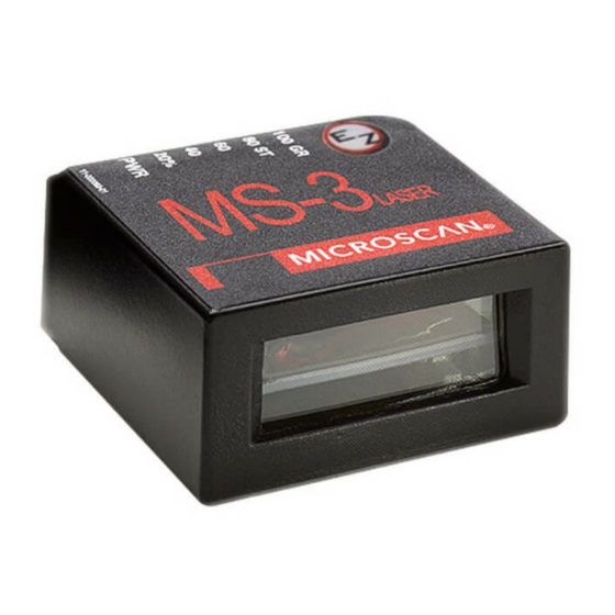
Manuals and User Guides for Microscan MS-3. We have
4
Microscan MS-3 manuals available for free PDF download: User Manual, Manual Book, Quick Start Manual
Microscan MS-3 User Manual (242 pages)
Laser scanner
Brand:
Microscan
| Category:
Scanner
| Size: 7 MB
Table of Contents
Table of Contents
4
Chapter 1 Quick Start
9
About this Manual
9
Figure 1-1 Hardware Required
14
Step 1 Hardware Required
14
Figure 1-2 Hardware Connections
15
Step 2 Connect the System
15
Step 3 Position Symbol and Scanner
16
Step 4 Install ESP
17
Step 5 Select Reader Model
18
Step 6 Autoconnect
19
Step 7 Test for Read Rate
20
Figure 1-4 Calibration
21
Step 8 Calibrate the Reader
21
Figure 1-5 Save Settings
22
Step 9 Save Calibration Settings for Power-On
22
Step 10 Configure the Reader
23
Chapter 2 Using ESP
26
Setup Mode
26
Application Mode
27
Pulldown Menus
28
Figure 2-1 How Settings Are Saved
28
Connect Menu
33
View
35
Navigating in ESP
36
Send/Receive Options
37
Advanced Options
38
Chapter 3 Communications
39
Communications by ESP
40
Communications by Serial Command
40
Password Protection
41
RS-232/422 Host Port
42
Host Port Protocol
43
User Defined Point-To-Point
45
User Defined Multidrop
47
RS-232 Auxiliary Port
49
Auxiliary Port Mode
51
Transparent Mode
52
Full Duplex Mode
54
Daisy Chain Mode
55
Daisy Chain ID
57
Preamble
58
Postamble
59
LRC Status
60
Intercharacter Delay
60
Figure 6-6 Read Cycle
61
Chapter 4 Read Cycle
62
Read Cycle by ESP
62
Read Cycle by Serial Command
62
Multisymbol
63
Number of Symbols
64
Trigger Mode
66
Figure 4-2 External Level Trigger
68
Figure 4-3 Trigger Edge
69
External Trigger Edge
69
Trigger Filter Duration
71
Serial Trigger
72
End of Read Cycle
74
End of Read Cycle Mode
74
Timeout or New Trigger
75
Decodes before Output
76
Scanner Setup
77
Gain Level
77
Scan Speed
77
Laser Power
78
Laser Setup
81
Figure 4-4 Laser on Position
82
Chapter 5 Symbologies
84
Symbology by Serial Command
84
Code 39
85
Full Ascii Set (Code)
87
Code 128
88
Ean-128 Status
90
Interleaved 2 of 5
95
Codabar
99
Upc/Ean
103
Ean Status
103
Upc-E Output to Upc-A (Upc/Ean)
105
Code 93
106
Pharmacode
107
Fixed Threshold Value (Pharmacode)
108
Narrow Margins
109
Symbology ID
110
Background Color
111
Autodiscriminate
111
Chapter 6 I/O Parameters
113
Output Conditions by ESP Menu
114
I/O Parameters by Serial Command
115
Symbol Data Output
116
When to Output Symbol Data
118
Message Output
119
Noread Message
120
Bad Symbol Message
121
No Symbol Message
122
Beeper
123
Partial Output
124
Serial Verification
125
Test Button
127
Default on Power-On
127
Global Status
127
Table 6-1-Test Button Options
128
Test Button Modes
128
Output 1
130
Output Mode
132
Trend Analysis Mode
133
Output 1
134
Output 2
136
Output 3
137
Quality Output
138
Chapter 7 Matchcode
139
Matchcode by ESP
140
Matchcode by Serial Command
140
Overview of Matchcode
141
Using Master Symbols
141
Matchcode Type
142
Sequential Matching
142
Match Length
144
Sequence on Noread
145
Sequence on Mismatch
146
New Master Pin
147
Master Symbol Database
148
Delete Master Symbol Data
148
Chapter 8 Diagnostics
149
Diagnostics by ESP Menu
150
Diagnostics by Serial Command
150
Diagnostic Messages Overview
151
Counts
152
Hours Since Last Reset
154
Laser High
155
Laser Low
156
Service Message
157
Chapter 9 Calibration
159
Figure 9-7 Calibration Display
161
Calibration by Esp
161
Figure 9-8 Embedded Calibration Setup Menu
162
Auto Frame
164
Figure 9-9 Auto Frame Defaults
164
Chapter 10 Terminal Mode
168
Terminal Window
168
Figure 10-11 Terminal Window
168
Find Function
169
Macros
170
Terminal Window Functions
171
Chapter 11 Utilities
173
Utilities by ESP Menu
174
Summary of Utilities Commands
175
Table 11-2-Utilities Commands
175
Read Rate
177
Counters
178
Master Database
180
Table 11-3-Maximum Characters for Master Symbol Database
181
Enter Master Symbol Data
181
Digital Bar Code
183
Firmware
184
Device Control
185
Symbol Type
187
Defaulting/Saving/Resetting
188
Table 11-4-Software Reset/Save/Recall Commands
188
Microscan Grading
189
Reader Status Requests
191
Table 11-5-Hex Value to Binary Conversion
191
Table 11-6-MS-3 FIS-0003 Laser Scanner Status
191
Appendices
193
Appendix A General Specifications
194
Figure A-1 MS-3 Integral Right Angle Laser Scanner
194
Figure A-1 MS-3 Laser Scanner
194
Table A-1-MS-3 Laser High Density Ranges
195
Table A-2-MS-3 Laser Low Density Ranges
195
Appendix B Electrical Specifications
196
Table A-3-MS-3 Laser Connector, 15-Pin Socket
196
Electrical Specifications
198
Appendix C Connectivity
199
Figure A-2 MS-3/IB-131 Typical Setup
199
Table A-4-Host 25-Pin Connector
201
Table A-5-Trigger 4-Pin Connector
201
Table A-6-Power 3-Pin Connector
201
Table A-7-Scanner 15-Pin Connector
201
Table A-8-Network 25-Pin Connector
201
Figure A-5 IB-131 Mechanical
202
Figure A-6 IB-131 Multidrop Setup
203
Figure A-7 Scanner/Ib-131 Daisy Chain Setup
204
Appendix D Serial Configuration Commands
205
Table A-9-Serial Configuration Commands
205
Figure A-8 Hyperterminal Dialog
207
Appendix E Serial Command Format
208
Appendix F ASCII Table
210
Table A-10-ASCII Table with Control Characters
210
Table A-11-Communication Protocol Commands
210
Appendix G Defaulting/Saving/Resetting
212
Table A-12-Software Reset/Save/Recall Commands
212
Appendix H PDF Symbology
215
Appendix I Symbol Configuration
218
Appendix J Object Detector
220
Figure A-1 Object Detector
220
Appendix K Formulas for Number of Decodes
221
Figure A-2 Ladder
221
Figure A-3 Picket Fence
221
Figure A-4 Angled Picket Fence
222
Appendix L Operational Tips
223
Appendix M Interface Standards
224
Appendix N Multidrop Communications
225
Figure A-5 Polling Sequence
227
Figure A-6 Polling Sequence
228
Table A-13-Multidrop Addresses
229
Appendix O Glossary of Terms
230
Index
237
Advertisement
Microscan MS-3 Manual Book (202 pages)
Brand:
Microscan
| Category:
Scanner
| Size: 2 MB
Table of Contents
Table of Contents
4
About this Manual
9
Product Labels
10
Warning and Caution Summary
11
Chapter 1 Quick Start
14
Step 1 Hardware Required
14
Figure 1-1 Hardware Required
14
Step 2 Connect the System
15
Figure 1-2 Hardware Connections
15
Step 3 Initiate Communications
16
Figure 1-3 Hyperterminal Dialog
16
Step 4 Position Symbol and Scanner
17
Figure 1-4 Low Density Ranges
17
Figure 1-5 High Density Ranges
17
Step 5 Start Calibration
18
Step 6 Test for Read Rate
19
Step 7 Save Settings
20
Chapter 2 Communications
21
Host Port Parameters
24
RS422 Status
25
Auxiliary Port
26
Full Duplex Mode
29
Daisy Chain Mode
30
Chapter 3 Protocol
37
Protocol
38
Lrc
43
Response Timeout
44
Intercharacter Delay
45
Preamble Characters
46
Postamble Characters
47
Chapter 4 Read Cycle/Trigger
51
Trigger Mode
52
Figure 4-1 Trigger Level
54
Figure 4-2 Trigger Edge
55
Trigger Filter Duration
57
External Trigger State
58
Serial Trigger Character
59
Good Decode Reads
62
Read Cycle
63
Multisymbol
66
Chapter 5 Symbology
71
Symbology by Serial Command
71
Autodiscriminate
72
Narrow Margins
73
Symbology ID
74
Background Color
75
Code 39
76
Codabar
79
Interleaved 2 of 5
82
Upc/Ean
85
Code 128
88
Ucc/Ean-128
89
Code 93
92
Pharmacode
93
Matchcode by Serial Command
96
Chapter 6 Matchcode
97
Overview of Matchcode
98
Using Master Symbols
99
Matchcode Type
100
Match Length
101
Sequence on Noread
103
Sequence on Mismatch
104
Master Symbol Database
105
Table 6-1 Maximum Characters for Master Symbol Database
106
Delete Master Symbol Data
107
New Master Pin
108
Chapter 7 Scanner Setup
111
Scan Speed
112
Laser On/Off Status
113
Laser Framing
114
Figure 7-1 Laser on Position
115
Figure 7-2 Laser off Position
116
Laser Power
117
Automatic Gain Control
118
Transition Counter
120
Bar Detection
121
Chapter 8 Data Outputs
126
Symbol Output
126
Figure 8-1 Read Cycle
128
Message Output
129
Figure 8-2 Output Message Flow
129
Noread Message
130
Bad Symbol Message
131
No Symbol Message
132
Serial Verification
133
Quality Output
135
Partial Output
136
Beeper Output
137
Chapter 9 Discrete I/O
139
Output 1
139
Output 2
139
Output 3
142
Diagnostics by Serial Command
146
Chapter 10 Diagnostics
147
Warning Message Status
149
Laser High Warning
150
Laser Low Warning
151
NOVRAM Corrupt Warning Status
152
Power-On Count
153
Time Since Last Reset
154
Table 11-1 Summary of Utility Serial Commands
156
Chapter 11 Utilities
158
Counters
158
Part Number
159
Checksum
160
Read Rate
161
Device Control
162
Symbol Type
164
Defaulting/Saving/Resetting
165
Table 11-2 Software Reset/Save/Recall Commands
165
Code Types Enable Commands
167
Master Symbol Database
167
Scanner Status Requests
168
Table 11-4 MS-3 Laser Scanner Status
168
Appendices
169
Appendix A General Specifications
170
Figure A-1 MS-3 Laser Dimensions
170
Table A-1 FIS Numbers
171
Appendix B Electrical Specifications
172
Table A-2 MS-3 Laser Host Connector, 15-Pin
172
Appendix C ADP Interface Box
173
Figure A-2 ADP RS-232 Interface Box
173
Table A-3 Host 25-Pin Connector
173
Table A-4 Trigger 6-Pin Connector
173
Table A-5 Power 5-Pin Connector
173
Table A-6 Scanner 15-Pin Connector
173
Appendix D Serial Configuration Commands
174
Table A-7 Serial Configuration Commands in Numeric Order
174
Appendix E Serial Command Format
176
Appendix F ASCII Table
178
Table A-8 ASCII Table with Control Characters
178
Table A-9 Communication Protocol Commands
179
Appendix G Defaulting/Saving/Resetting
180
Table A-10 Software Reset/Save/Recall Commands
180
Reader Status Requests
183
Appendix H Symbol Configuration
184
Appendix I Object Detector
186
Figure A-1 Object Detector
186
Appendix J Formulas for Number of Decodes
187
Figure A-2 Ladder
187
Figure A-3 Picket Fence
187
Figure A-4 Angled Picket Fence
188
Appendix K Operational Tips
189
Appendix L Embedded Menus
190
Appendix M Interface Standards
191
Appendix N Multidrop Communications
192
Figure A-5 Polling Sequence
194
Figure A-6 Polling Sequence
195
Appendix O Glossary of Terms
197
Microscan MS-3 User Manual (106 pages)
CCD Reader
Brand:
Microscan
| Category:
Barcode Reader
| Size: 1 MB
Table of Contents
Table of Contents
4
About this Manual
7
Host Communications
7
Product Labels
8
Chapter 1 Quick Start
10
Step 1 Connect the System
10
Figure 1-1 Hardware Connections
10
Step 2 Install ESP
11
Step 3 Select Reader Model
12
Step 4 Autoconnect
13
Step 5 Position Symbol and Reader
14
Figure 1-2 Symbol/Reader Position
14
Step 6 Configure the Reader
15
Chapter 2 Communications
17
Communications by ESP
18
Communications by Serial Command
18
Host Port Connections
19
Host Port Protocol
20
Preamble
22
Postamble
23
Chapter 3 Read Cycle
26
Read Cycle by ESP
26
Read Cycle by Serial Command
26
Read Cycle Differences in the MS-3 CCD
27
Number of Symbols
28
Time between Identical Decodes
29
Continuous Read
30
Trigger Mode
30
Figure 3-1 External Level Trigger
31
External Trigger Edge
32
Figure 3-2 Trigger Edge
32
Serial Data
33
Serial Data or External Edge
33
No Decode Timeout
35
Decodes before Output
36
Noread Message
37
Reader Setup
38
Figure 3-3 Filter Selection
40
Chapter 4 Symbologies
41
Symbologies by ESP
42
Symbologies by Serial Command
43
Code 39
44
Code 128/EAN
46
Interleaved 2 of 5
47
Codabar
50
Upc/Ean
52
Output Format
54
Code 93
55
Industrial 2 of 5
56
Symbol Length #2 (Industrial 2 of 5)
58
MSI Code
59
Plessey Code
60
RSS Expanded
61
RSS Limited
62
CCD Reader User's Manual
62
Symbology ID
64
Chapter 5 Utilities
66
Utilities by ESP Menu
66
Summary of Utilities Commands
66
Firmware
67
Device Control
68
Defaulting/Saving/Resetting
68
Reader Status Requests
69
Chapter 6 Terminal Mode
72
Terminal Window
72
Figure 6-1 Terminal Window
72
Find Function
73
Macros
74
Editing a Macro
74
Terminal Window Functions
75
Appendices
77
Appendix A General Specifications
78
Figure A-1 MS-3 CCD Dimensions
78
Figure A-3 MS-3 CCD Read Ranges
79
Appendix B Electrical Specifications
80
Appendix C Connectivity
81
Figure A-5 IC-332 READER Pinouts
81
Figure A-7 IB-131 Mechanical
85
Appendix D Serial Configuration Commands
86
Figure A-8 Hyperterminal Dialog
87
Appendix E Serial Command Format
88
Serial Utility Commands
88
Appendix F ASCII Table
90
Appendix G Defaulting/Saving/Resetting
91
Appendix H Object Detector
93
Figure A-1 Object Detector
93
Appendix I Formulas for Number of Decodes
94
Figure A-2 Ladder
94
Figure A-3 Picket Fence
94
Figure A-4 Angled Picket Fence
95
Appendix J Operational Tips
96
Appendix K Glossary of Terms
97
Advertisement
Microscan MS-3 Quick Start Manual (13 pages)
Laser Scanner
Brand:
Microscan
| Category:
Scanner
| Size: 0 MB
Table of Contents
Quick Start Guide
1
Step 1 -Check Required Hardware
3
Step 2 -Connect the System
4
Step 3 -Install ESP
5
Step 4 -Select Scanner Model
6
Step 6 -Position Symbol and Scanner
8
Step 7 -Test Read Rate
9
Step 8 -Calibrate the Scanner
10
Step 10 -Configure the Scanner
12
Advertisement
Related Products
Microscan MS-9
Microscan MS-7100
Microscan MS-7180
Microscan MS-850
Microscan MS-610
Microscan MS-710
Microscan MS-890
Microscan MS-810
Microscan MS-615
Microscan MS-3000
Microscan Categories
Barcode Reader
Scanner
Digital Camera
Laboratory Equipment
Card Reader
More Microscan Manuals
Login
Sign In
OR
Sign in with Facebook
Sign in with Google
Upload manual
Upload from disk
Upload from URL