Microscan MS-3 User Manual
Laser scanner
Hide thumbs
Also See for MS-3:
- Quick start manual (13 pages) ,
- User manual (106 pages) ,
- Manual book (202 pages)
Table of Contents
Advertisement
Advertisement
Table of Contents

Related Manuals for Microscan MS-3


Summary of Contents for Microscan MS-3
- Page 1 MS-3 Laser Scanner User’s Manual P/N 83-000003 Rev E...
- Page 2 All rights reserved. The information contained herein is proprietary and is provided solely for the purpose of allowing customers to operate and/or service Microscan manufactured equipment and is not to be released, reproduced, or used for any other purpose without written permission of Microscan.
- Page 3 Limitation of Liability In no event shall Microscan Systems Inc. be liable to you or any third party for any special, inci- dental, or consequential damages (including, without limitation, indirect, special, punitive, or exemplary damages for loss of business, loss of profits, business interruption, or loss of business information), whether in contract, tort, or otherwise, even if Microscan Systems Inc.
-
Page 4: Table Of Contents
Read Cycle by ESP ..................4-2 Read Cycle by Serial Command 2 Multisymbol ....................4-3 Number of Symbols ..................4-4 Serial Trigger .................... 4-12 End of Read Cycle ..................4-14 Decodes Before Output ................4-16 MS-3 Laser Scanner User’s Manual... - Page 5 Matchcode Type..................7-4 New Master Pin ................... 7-9 Master Symbol Database ................7-10 Chapter 8 Diagnostics Diagnostics by ESP Menu................8-2 Diagnostics by Serial Command ..............8-2 Diagnostic Messages Overview ..............8-3 Counts ......................8-4 MS-3 Laser Scanner User’s Manual...
- Page 6 Appendix I Symbol Configuration..............A-26 Appendix J Object Detector ..............A-28 Appendix K Formulas for Number of Decodes..........A-29 Appendix L Operational Tips..............A-31 Appendix M Interface Standards...............A-32 Appendix N Multidrop Communications ............A-33 Appendix O Glossary of Terms ..............A-38 Chapter 1 Index MS-3 Laser Scanner User’s Manual...
- Page 7 Figure 9-9 Auto Frame Defaults ..............9-6 Figure 9-10 Constrained Scan Beam Width ..........9-6 Figure 10-11 Terminal Window ..............10-2 Figure A-1 MS-3 Laser Scanner ..............A-2 Figure A-1 MS-3 Integral Right Angle Laser Scanner ..................A-2 Figure A-2 MS-3/IB-131 Typical Setup ............A-7 Figure A-3 IC-331 SCANNER Pinouts ................A-8...
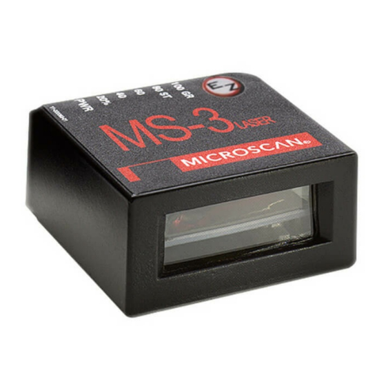
- Page 8 Table A-13-Multidrop Addresses ..............A-37 About the MS-3 Laser The MS-3 Laser scanner is a ultra-compact scanner that can decode high density sym- bols from 2 to 10 inches at a 70 degrees scan angle with scan rates of 300 to 1000 decodes per second with a low power draw of 300 mA at 5V.
-
Page 9: Chapter 1 Quick Start
Cross-references are highlighted in blue. Web links and outside references are high- lighted in blue bold italics. References to menu topics are highlighted in Bold Initial Caps. References to topic headings within this manual or other documents are enclosed in quotation marks. MS-3 Laser Scanner User’s Manual... - Page 10 Product Labels The following labels are located on the top, side, and bottom of the MS-3 FIS-0003 Reader: 2 Watts ma x. w ww.micr os ca n.com 1201 S W 7th St. C L ASS B DEVI CE Renton, WA 98055 hel pdesk@mi cr oscan.
- Page 11 Systems warranty and could expose the user to laser diode power of up to 7 mW. WARNING The laser beam can be harmful to eyesight. Avoid eye contact with the laser beam. Never point the beam at other people, or in a direction where people may be passing. MS-3 Laser Scanner User’s Manual...
- Page 12 MS-3 Laser Scanner User’s Manual...
- Page 13 This section is designed to get the scanner up and running quickly so the user can get a sense of its capabilities and test sample bar code symbols. Detailed setup information for configuring the scanner for your specific application can be obtained in the subse- quent chapters. MS-3 Laser Scanner User’s Manual...
-
Page 14: Step 1 Hardware Required
99-400005-02 IB-131 Interface box Host computer P/N 61-300026-01 Null modem configuration cable 97-100004-05 (120VAC) Power supply 97-100004-06 (240VAC) 99-4400001-10 Optional object detector a. See figure 1-1 for diagram of system. Scanner Figure 1-1 Hardware Required MS-3 Laser Scanner User’s Manual... -
Page 15: Step 2 Connect The System
3 feet. RS232 cabling from the IB-131 to the host can be up to 47 feet provided it does not include power input. 2. If using your own null modem RS232 host cable, be certain that the host’s TxD connects to the reader’s RxD and the reader’s TxD connects to the host’s RxD. MS-3 Laser Scanner User’s Manual... -
Page 16: Step 3 Position Symbol And Scanner
Note: If using an I 2/5 symbol, verify that the number of characters in the symbol being scanned matches the symbol length enabled for the I 2/5 symbol type. (Default is 10 and 6.) “Interleaved 2 of 5” on page 5-13. 1. Consult table A-1 table A-2 on page A-3. MS-3 Laser Scanner User’s Manual... -
Page 17: Step 4 Install Esp
Easy Setup Program.) With your scanner connected to a host computer with Windows™ operating system, you can use the ESP to configure and control the reader. 1. Insert your Microscan CD into your computer’s CD drive. 2. Launch Setup.exe under ESP and follow the prompts. -
Page 18: Step 5 Select Reader Model
If you do not want to make this selection every time you load ESP, uncheck Show this window at Startup. 2. Select the default name, for example MS-3 Laser-1, or type in a file name of your choice and click 3. Click when the connect to the reader dialog appears. MS-3 Laser Scanner User’s Manual... -
Page 19: Step 6 Autoconnect
Tip: If you do not see either the CONNECTED or DISCONNECTED message at the bot- tom of your dialog, try expanding the ESP window horizontally. Important Note: When you connect to the reader, the reader’s settings will be loaded into ESP. MS-3 Laser Scanner User’s Manual... -
Page 20: Step 7 Test For Read Rate
With this test you can learn the percentage of decodes per images captured by observ- ing the LEDs (20% through 100%) on the top of the MS-3 which are active during a read rate test. If the results are not satisfactory, move on to “Calibrate the Reader”... -
Page 21: Step 8 Calibrate The Reader
LEDs turn TEST Read rate amber to indicate that the calibra- performance 100% tion is in progress. LEDs The scanner will beep once at the end of calibration. 11-000063-01 Figure 1-4 Calibration MS-3 Laser Scanner User’s Manual... -
Page 22: Step 9 Save Calibration Settings For Power-On
Step 9 — Save Calibration Settings for Power-on After calibrating the MS-3, you can save your new settings to be available on power-on. By ESP Caution: If you have settings in the scanner that you have not yet loaded into ESP, the ESP settings will overwrite the scanner’s settings when you save. -
Page 23: Step 10 Configure The Reader
“Summary of Utilities Commands” on page 11-3. Note: You can learn the current setting of any parameter by inserting a question mark after the number, as in <K100?> To see all “K” commands, send <K?>. MS-3 Laser Scanner User’s Manual 1-11... - Page 24 MS-3 Laser Scanner User’s Manual 1-12...
- Page 25 When you start up ESP, unless otherwise specified, you will enter the Setup Mode initial setup. From there, you move easily into the App Mode (application mode) where you can access several configuration and utilities menus. MS-3 Laser Reader User’s Manual...
-
Page 26: Setup Mode
Note: This view may be slightly different for each model. Saves Calibration results (if available) Ends the read rate test On some models, clicking Auto Discriminate will enable most available symbology types. MS-3 Laser Reader User’s Manual... -
Page 27: Application Mode
Note: For specific information on any of the icons shown above in the operations bar or configuration bar, see specific chapters in this document. MS-3 Laser Reader User’s Manual... -
Page 28: Pulldown Menus
Host hard drive Figure 2-1 How Settings are Saved Import/Export Import converts the ASCII settings from a text file to ESP configuration settings. Export converts the active ESP configuration settings to an ASCII text file. MS-3 Laser Reader User’s Manual... - Page 29 Model menu and that the same menu is repeated when clicking the Switch Model icon. When you save your ESP file, you will be saving the settings of all the models defined in a single ESP file. MS-3 Laser Reader User’s Manual...
- Page 30 At startup, loads the reader’s settings into ESP. (This is not recommended if you want to preserve your ESP settings for future use.) Enable ‘Send and Save as Factory Settings’ At startup, enables the Send and Save as Factory option in the Send/Recv com- mand. MS-3 Laser Reader User’s Manual...
- Page 31 Sets the font characteristics for text that is echoed back to the screen from the reader. Toolbar Style By user selection, displays toolbar buttons as icons, text only, or both (default). Note: See also Chapter 14, “Terminal Mode.” MS-3 Laser Reader User’s Manual...
- Page 32 Whatever you type into the Document Memo will appear in a text box whenever your cursor hovers over the Document Memo option. Model Memo Memos created in Model Memo are specific to the model enabled when the message was created. MS-3 Laser Reader User’s Manual...
-
Page 33: Connect Menu
ESP is not currently connected to the multidrop concentrator. Do you wish to establish a connec- tion now? 3. Click Yes. You will see a Serial Communication Parameters dialog as shown on the next page. MS-3 Laser Reader User’s Manual... - Page 34 Serial Communication Parameters dialog and make the corrections. 8. Follow the same procedure for connecting other scanners to your multidrop network. Note: For more information, see your scanner user’s manual or Microscan’s MS-5000 Multidrop Concentrator User’s Manual, 83-005000. MS-3 Laser Reader User’s Manual...
-
Page 35: View
To configure the size, text and caption parameters, “Bar Code Options tab” on page 2-8. MS-3 Laser Reader User’s Manual 2-11... -
Page 36: Navigating In Esp
Left click again on the Right click on the open screen and select open screen to complete Save to Reader to implement the command the selection. in the reader. MS-3 Laser Reader User’s Manual 2-12... -
Page 37: Send/Receive Options
Customer Defaults’ in ESP Preferences in the Options menu.) Use this to save your own set of default settings that you can quickly retrieve with a <Zrc> command. For more on defaulting and saving settings, see “Defaulting/Saving/Resetting” on page A-20. MS-3 Laser Reader User’s Manual 2-13... -
Page 38: Advanced Options
Also, if there is a corresponding ESP menu item, the ESP Value column for that item will be blank following a Receive from Reader com- mand. 1. From the Send/Recv button or right-clicking from within the tree menus. MS-3 Laser Reader User’s Manual 2-14... -
Page 39: Communications
Data Bits = Seven Flow Control = None Note: You can learn the current setting of any parameter by inserting a question mark after the number, as in <K100?> To see all “K” commands, send <K?>. MS-3 Laser Scanner User’s Manual... -
Page 40: Communications By Esp
Host Protocol <K140, protocol> Host RS422 Status <K102, status> <K101,aux port mode,baud rate,parity,stop bits,data Aux Port Parameters bits,daisy chain status,daisy chain ID> Preamble <K141,preambole status,preamble> Postamble <K142,postamble status,postamble> LRC Status <K145,status> Intercharacter Delay <K144,intercharacter delay> MS-3 Laser Scanner User’s Manual... -
Page 41: Password Protection
Serial Cmd: <K733 password,new password> Note: Follow this with a <Z> or <Zc> to save for power-on. Default: MICRO Options: Any ASCII string up to 8 characters. MS-3 Laser Scanner User’s Manual... -
Page 42: Rs-232/422 Host Port
Only changed if necessary to match host setting. Definition: One or two bits added to the end of each character to indicate the end of the character. Serial Cmd: <K100,baud rate,parity,stop bits,data bits> Default: Options: 0 = One 1 = Two MS-3 Laser Scanner User’s Manual... -
Page 43: Host Port Protocol
Point-to-Point (standard) Usage: Used only with RS232 or RS422. Definition: Standard Point-to-Point requires no address and sends data to the host whenever it is available, without any request or handshake from the host. Serial Cmd: <K140,0> MS-3 Laser Scanner User’s Manual... - Page 44 Definition: Like Point-to-Point, Polling Mode D requires a dedicated connection to the host; but unlike Point-to-Point, it requires an address and must wait for a poll from the host before sending data. Serial Cmd: <K140,4> MS-3 Laser Scanner User’s Manual...
-
Page 45: User Defined Point-To-Point
Serial Cmd: If selecting Multidrop fan address must be defined and appended to the command string. Format: <K100,5,address[01 to 50]> Note: Scanners linking up to a Microscan MS-5000 multidrop concentrator must be configured in standard multidrop protocol. User Defined Point-to-Point Usage: Useful for developing custom protocols in polled or unpolled mode. - Page 46 If From Host is disabled, the defined protocol is not included. If From Host is enabled, the defined protocol must be included. Serial Cmd: <K140,6,RES,address,REQ,EOT,STX,ETX,ACK,NAK,from host> Default: Disabled Options: 0 = Disabled 1 = Enabled MS-3 Laser Scanner User’s Manual...
-
Page 47: User Defined Multidrop
Note: Typically, parameters in User Defined Multidrop are defined by first enabling Multidrop, then enabling User Defined Multidrop. This pre-loads multidrop charac- ters into the parameters. Then changes are made to individual characters to match the host or other requirements. MS-3 Laser Scanner User’s Manual... - Page 48 Whenever RS422 is disabled, RS232 is enabled in the background. However, when Mul- tidrop is enabled, the functioning protocol is RS485 regardless of the displayed status of RS422. Before enabling RS422, first double-check that Multidrop is not enabled. MS-3 Laser Scanner User’s Manual 3-10...
-
Page 49: Rs-232 Auxiliary Port
Default: 9600 Options: 0 = 600 3 = 4800 6 = 38.4 K 1 = 1200 4 = 9600 7 = 57.6 K 2 = 2400 5 = 19.2 K 8 = 115.2 K MS-3 Laser Scanner User’s Manual 3-11... - Page 50 Only changed if necessary to match host setting. Definition: Number of bits in each character. Serial Cmd: <K101,aux port mode,baud rate,parity,stop bits,data bits,daisy chain ID status,daisy chain ID> Default: Seven Options: 0 = Seven 1 = Eight MS-3 Laser Scanner User’s Manual 3-12...
-
Page 51: Auxiliary Port Mode
ID status,daisy chain ID> Default: Disabled Options: 0 = Disabled 1 = Transparent 2 = Half duplex 3 = Full duplex 4 = Daisy chain 5 = Command Processing MS-3 Laser Scanner User’s Manual 3-13... -
Page 52: Transparent Mode
Host • All host data is echoed to the auxiliary port in Port unpolled and polled mode. Scanner Serial Cmd: <K101,aux port mode,baud rate,parity,stop bits,data bits,daisy chain ID status,daisy chain ID> 1 = Transparent MS-3 Laser Scanner User’s Manual 3-14... - Page 53 Scanner • All host data is echoed to the auxiliary port in unpolled mode. Host Port Scanner Serial Cmd: <K101,aux port mode,baud rate,parity,stop bits,data bits,daisy chain ID status,daisy chain ID> 2 = Half Duplex MS-3 Laser Scanner User’s Manual 3-15...
-
Page 54: Full Duplex Mode
Data initiated from the Host Host • All host data is echoed to the auxiliary port in Port unpolled mode. Scanner Serial Cmd: <K101,aux port mode,baud rate,parity,stop bits,data bits,daisy chain ID status,daisy chain ID> 3 = Full duplex MS-3 Laser Scanner User’s Manual 3-16... -
Page 55: Daisy Chain Mode
The above example is based on the best case. Other factors such as baud rate, dynamic focus timing, number of characters in a given symbol, and the number of slaves in the daisy chain can affect tim- ing and may need to be included in your calculations for complete accuracy. MS-3 Laser Scanner User’s Manual 3-17... - Page 56 2. If a reset occurs, all data will be transmitted to the host port. Serial Cmd: <K101,aux port mode,baud rate,parity,stop bits,data bits,daisy chain ID status,daisy chain ID> Options: 5 = Command Processing MS-3 Laser Scanner User’s Manual 3-18...
-
Page 57: Daisy Chain Id
A one or two character prefix which identifies the particular daisy chain scanner from which the data is being sent. Serial Cmd: <K101,aux port mode,baud rate,parity,stop bits,data bits,daisy chain ID status,daisy chain ID> Default: Options: Any one or two ASCII characters. MS-3 Laser Scanner User’s Manual 3-19... -
Page 58: Preamble
This has the effect of allowing the control key to be recognized as a part of the control character. Next hold down the control key while typing the desired char- acter. Example: Space CNTL-m to enter ^M. MS-3 Laser Scanner User’s Manual 3-20... -
Page 59: Postamble
This has the effect of allowing the control key to be recognized as a part of the control character. Next hold down the control key while typing the desired char- acter. Example: Space CNTL-m Space CNTL-j to enter ^M^J. MS-3 Laser Scanner User’s Manual 3-21... -
Page 60: Lrc Status
The time interval in milliseconds between individual characters transmit- ted from the scanner to the host. Serial Cmd: <K144,intercharacter delay> Default: Options: 0 to 255 (in milliseconds). Zero (0) causes no delay between characters. MS-3 Laser Scanner User’s Manual 3-22... -
Page 61: Figure 6-6 Read Cycle
ESP or serial commands. Note: You can learn the current setting of any parameter by inserting a question mark after the number, as in <K100?>. To see all “K” commands, send <K?>. MS-3 Laser Scanner User’s Manual... -
Page 62: Read Cycle By Esp
Scan Speed <K500,scan speed> Symbol Detect/Transition <K505, symbol detect status,transition counter> Maximum Element <K502, maximum element> Scan Width Enhance <K511,scan width enhance> <K700, laser on/off status,laser framing status,laser on position,laser Laser Controls off position,laser power> MS-3 Laser Scanner User’s Manual... -
Page 63: Multisymbol
4. The maximum number of characters in any one bar code (other than PDF417) is 64. 5. The maximum number of characters in a single scan line is (Code 39). 6. The maximum number of characters for all symbols is 392, includ- ing preamble, separators, and LRC. MS-3 Laser Scanner User’s Manual... -
Page 64: Number Of Symbols
Number of Symbols allows the user to define up to 12 bar code sym- bols that can be read in a single read cycle. Serial Cmd: <K222,number of symbols,multisymbol separator> Default: Options 1 to 6 MS-3 Laser Scanner User’s Manual... - Page 65 Note: If Multisymbol Separator has been changed to any character other than the default comma and you wish to re-define the separator as a comma, use ESP or the embedded menu. Default: (comma) Options: Any available ASCII character, except < > NUL. MS-3 Laser Scanner User’s Manual...
-
Page 66: Trigger Mode
In Continuous Read, trigger input options are disabled, the reader is always in the read cycle, and it will attempt to decode and output every scan crossing a symbol.When To Output and Noread options have no affect on Continuous Read. Serial Cmd: <K200,0> MS-3 Laser Scanner User’s Manual... - Page 67 Note: If Trigger is set to Continuous Read 1 Output, Number of Symbols will default back to 1 (if set to any number greater than 1). MS-3 Laser Scanner User’s Manual...
-
Page 68: Figure 4-2 External Level Trigger
Rising edge is the trigger signal associated with the appearance of an object. Falling edge is the trigger signal associated with the subsequent disappearance of the object. MS-3 Laser Scanner User’s Manual... -
Page 69: Figure 4-3 Trigger Edge
Rising edge is the trigger signal associated with the appearance of an object. Falling edge is the trigger signal associated with the subsequent disappearance of the object. MS-3 Laser Scanner User’s Manual... - Page 70 Definition: In this mode the reader accepts either a serial ASCII character or an external trigger pulse to start the read cycle. Serial Cmd: <K200,5> MS-3 Laser Scanner User’s Manual 4-10...
-
Page 71: Trigger Filter Duration
Users can select the trigger polarity that will operate with their systems. Definition: Determines whether a positive or negative transition will initiate the read cycle. Serial Cmd: <K202,external trigger state> Default: Positive Options: 0 = Negative 1 = Positive MS-3 Laser Scanner User’s Manual 4-11... -
Page 72: Serial Trigger
Any single ASCII character, including control characters, except NUL (00H), an existing host command character, or an on-line protocol char- acter. Note: Serial Data or Serial Data & Edge triggering mode must be enabled for Serial Trigger Character to take effect. MS-3 Laser Scanner User’s Manual 4-12... - Page 73 < and >. Serial Cmd: <K230,stop trigger character> Default: Null (disabled) Options: Two hex digits representing an ASCII character except <, >, XON and XOFF. Appendix F — “ASCII Table” for ASCII character information. MS-3 Laser Scanner User’s Manual 4-13...
-
Page 74: End Of Read Cycle
The next read cycle does not begin until the next rising edge trigger. New Trigger Usage: New Trigger is an effective way to end a read cycle when objects move past the scanner at irregular intervals (not timing dependent). MS-3 Laser Scanner User’s Manual 4-14... -
Page 75: Timeout Or New Trigger
Note: A minimum setting of 2 is recommended. Note: Timeout or Timeout or New Trigger under End of Read Cycle must be enabled for Read Cycle Timeout to take effect. MS-3 Laser Scanner User’s Manual 4-15... -
Page 76: Decodes Before Output
Note: Higher settings will decrease throughput speed. Serial Cmd: <K221,number before output,decodes before output mode> Default: Options: 1 to 255 MS-3 Laser Scanner User’s Manual 4-16... -
Page 77: Scanner Setup
Allows the user to set the number of scans per second by controlling the spinning mirror motor speed. Serial Cmd: <K500,scan speed> Default: (x 10) Low density scanner (x 10) High density scanner Options: 300 to 1000 MS-3 Laser Scanner User’s Manual 4-17... -
Page 78: Laser Power
Finds the leading edge of a symbol by looking for a 40 µS quiet zone fol- lowed by the number of transitions set in “Transition Counter” on page 4-20, stores the highest value of the samples, and adjusts the AGC accordingly at the end of the scan. MS-3 Laser Scanner User’s Manual 4-18... - Page 79 AGC routines. When enabled, a bad symbol or no symbol message can be output rather than a noread message. Serial Cmd: <K505,symbol detect status,transition counter> Default: Disabled Options: 0 = Disabled 1 = Enabled MS-3 Laser Scanner User’s Manual 4-19...
- Page 80 70-80% of total scan width. Definition: Scan width Enhance tends to trade depth for width. Disable if outside edge/long range performance is needed. Serial Cmd: <K511,scan width enhance> Default: Enabled Options: 0 = Disabled 1 = Enabled MS-3 Laser Scanner User’s Manual 4-20...
-
Page 81: Laser Setup
Note: Because scan widths are not always perfectly symmetrical, the most effective way to setup laser framing is to experiment with the Laser On Position and Laser Off Position commands until you get the best results. MS-3 Laser Scanner User’s Manual 4-21... -
Page 82: Figure 4-4 Laser On Position
Laser On Posi- tion for an actual laser scan to take place. 4 5 L Off P Serial Cmd: <K700,laser on/off status,laser framing status,laser on position,laser position,laser power> Default: Options: 20 to 100 MS-3 Laser Scanner User’s Manual 4-22... - Page 83 ESP or serial commands. 1. If using an I 2/5 symbol, verify that the number of characters in the symbol being scanned matches the code length enabled for the I 2/5 symbol type (default is 10 and 6). MS-3 Laser Scanner User’s Manual...
-
Page 84: Symbology By Serial Command
Code 93 <K475,status,fixed symbol length status,symbol length> <K477,status,fixed bar length status,fixed bar length,min. no. of Pharmacode bars,bar widths,direction,fixed threshold value> Narrow Margins/ <K450, narrow margins status,symbology ID status> Symbology ID Background Color <K451, background color> MS-3 Laser Scanner User’s Manual... -
Page 85: Code 39
Serial Cmd: <K470,status,check digit status,check digit output,large intercharacter gap,fixed symbol length status,symbol length,full ASCII set> Default: Disabled Options: 0 = Disabled 1 = Enabled MS-3 Laser Scanner User’s Manual... - Page 86 When enabled, the scanner can read symbols with gaps between symbol characters that exceed three times (3x) the narrow element width. Serial Cmd: <K470,status,check digit status,check digit output,large intercharac- gap,fixed symbol length status,symbol length,full ASCII set> Default: Disabled Options: 0 = Disabled 1 = Enabled MS-3 Laser Scanner User’s Manual...
-
Page 87: Full Ascii Set (Code)
ASCII character set, from 0 to 255. Serial Cmd: <K470,status,check digit status,check digit output,large intercharacter gap,fixed symbol length status,symbol length,full ASCII set> Default: Disabled Options: 0 = Disabled 1 = Enabled MS-3 Laser Scanner User’s Manual... -
Page 88: Code 128
Code 128 Status Serial Cmd: <K474,status,fixed symbol length status,fixed symbol length,EAN-128 status,output format,application record separator status,application record separator character,application record brackets,application record padding> Default: Disabled Options: 0 = Disabled 1 = Enabled MS-3 Laser Scanner User’s Manual... - Page 89 <K474,status,fixed symbol length status,fixed symbol length,EAN-128 status,output format,application record separator status,application record separator character,application record brackets,application record padding> Default: Options: 1 to 64 Note: Fixed Symbol Length Status must be enabled for Symbol Length to take effect. MS-3 Laser Scanner User’s Manual...
-
Page 90: Ean-128 Status
If set to Enabled, symbols can be read with or without a function 1 character in the first position. If set to Required, the symbol must have a function 1 in the first position and conform to EAN format in order to decode the symbol. MS-3 Laser Scanner User’s Manual... - Page 91 (zeros) for variable length fields. Note: If an illegal Application Record format is detected, the scanner will process it as a noread and output a noread message (if enabled). MS-3 Laser Scanner User’s Manual...
- Page 92 <K474,status,fixed symbol length status,fixed symbol length,EAN-128 status,output format,application record separator status,application record separator character,application record brackets,application record padding> Default: (comma) Options: User Defined ASCII character Note: Has no effect unless Application Record Separator Status is enabled. MS-3 Laser Scanner User’s Manual 5-10...
- Page 93 Default: Disabled Options: 0 = Disabled 1 = Enabled Note: Output Format must be set to Application Record before this parameter can take effect. MS-3 Laser Scanner User’s Manual 5-11...
- Page 94 Default: Disabled Options: 0 = Disabled 1 = Enabled Note: Output Format must be set to Application Record before this parameter can take effect. MS-3 Laser Scanner User’s Manual 5-12...
-
Page 95: Interleaved 2 Of 5
Important: You must set Symbol Length in order to decode I 2/5 sym- bols. Interleaved 2 of 5 Status Serial Cmd: <K472,status,check digit status,check digit output status,symbol length #1,symbol length #2,unused,range mode> Default: Disabled Options: 0 = Disabled 1 = Enabled MS-3 Laser Scanner User’s Manual 5-13... - Page 96 When enabled, a check digit character is sent along with the bar symbol data for added data security. Serial Cmd: <K472,status,check digit status,check digit output status,symbol length #1,symbol length #2,unused,range mode> Default: Disabled Options: 0 = Disabled 1 = Enabled MS-3 Laser Scanner User’s Manual 5-14...
- Page 97 10 characters plus a check digit, then enable Symbol Length for 12. Note: Typically, when printing an I 2/5 symbol with an odd number of digits, a 0 will be added as the first character. MS-3 Laser Scanner User’s Manual 5-15...
- Page 98 <K472,status,check digit status,check digit output status,symbol length #1,symbol length #2,unused,range mode> Default: Options: 0 = Disabled 1 = Enabled When set to Enabled, minimum and maximum symbol lengths will be defined by Symbol Length #1 and Symbol Length #2. MS-3 Laser Scanner User’s Manual 5-16...
-
Page 99: Codabar
Serial Cmd: <K471,status,start & stop match status,start & stop output sta- tus,large intercharacter gap,fixed symbol length status,symbol length,check digit type,check digit status,check digit output status> Default: Enabled Options: 0 = Disabled 1 = Enabled MS-3 Laser Scanner User’s Manual 5-17... - Page 100 Serial Cmd: <K471,status,start & stop match status,start & stop output status,large intercharacter gap,fixed symbol length status,symbol length,check digit type,check digit output status> Default: Disabled Options: 0 = Disabled 1 = Enabled MS-3 Laser Scanner User’s Manual 5-18...
- Page 101 1 to 64 Note: Fixed Symbol Length Status must be enabled for Symbol Length to take effect. Note: Because of symbology limitations, setting Symbol Length to any number less than four will produce undetermined results. MS-3 Laser Scanner User’s Manual 5-19...
- Page 102 When disabled, symbol data is sent without the check digit. Serial Cmd: <K471,status,start & stop match,start & stop output status,large inter- character gap,fixed symbol length status,symbol length,check digit type,check digit output status> Default: Disabled Options: 0 = Disabled 1 = Enabled MS-3 Laser Scanner User’s Manual 5-20...
-
Page 103: Upc/Ean
13 digits when reading UPC version A symbols is not desired, disable EAN. Note: The extra character identifies the country of origin. Serial Cmd: <K473,UPC status,EAN status,supplementals status,separator sta- tus,separator character,unused,UPC-E output as UPC-A> Default: Disabled Options: 0 = Disabled 1 = Enabled MS-3 Laser Scanner User’s Manual 5-21... - Page 104 Note: Under no circumstances will supplemental symbol data be sent without a main symbol. Note: If additional symbols—other than the main or supplemental—will be read in the same read cycle, Number of symbols should be set accordingly. MS-3 Laser Scanner User’s Manual 5-22...
-
Page 105: Upc-E Output To Upc-A (Upc/Ean)
Useful for applications that require UPC-A output. Definition: Allows the user to change the output from UPC-E to UPC-A. Serial Cmd: <K473,UPC status,EAN status,supplementals status,separator sta- tus,separator character,unused,UPC-E output as UPC-A> Default: (comma) Options: Any ASCII character MS-3 Laser Scanner User’s Manual 5-23... -
Page 106: Code 93
(this does not include start and stop and check digit characters). The scanner ignores any symbol not having the specified length. Serial Cmd: <K475,status,fixed symbol length status,fixed symbol length> Default: Options: 1 to 64 MS-3 Laser Scanner User’s Manual 5-24... -
Page 107: Pharmacode
Default: Options: 2 to 16 Minimum Bars (Pharmacode) Serial Cmd: <K477,status,fixed bar count status, fixed bar count, min. no. of bars, bar widths,direction,fixed threshold value> Default: Options: 2 to 16 MS-3 Laser Scanner User’s Manual 5-25... -
Page 108: Fixed Threshold Value (Pharmacode)
Fixed Threshold Value (Pharmacode) Definition: Used when Bar Width Status field is set to Fixed Threshold Value. Serial Cmd: <K477,status,fixed bar count status,fixed bar count,min. no. of bars, bar widths,direction,fixed threshold value> Default: Options: 1 to 65535 MS-3 Laser Scanner User’s Manual 5-26... -
Page 109: Narrow Margins
Narrow Margins is enabled. Serial Cmd: <K450,narrow margins status,symbology id status> Default: Disabled Options: 0 = Disabled 1 = Enabled Note: Do not use Narrow Margins with Large Intercharacter Gap enabled in Code 39 or Codabar. MS-3 Laser Scanner User’s Manual 5-27... -
Page 110: Symbology Id
Code 39 symbol with Check Digit and Check Digit Output Status enabled and Full ASCII conversion performed. For Other Codes • For Code 128, a indicates EAN-128; otherwise the modifier is a 0. • For all other codes, the modifier is 0. MS-3 Laser Scanner User’s Manual 5-28... -
Page 111: Background Color
Note: If using an I 2/5 symbol, verify that the number of characters in the symbol being scanned matches the symbol length enabled for the I 2/5 symbol type (default is 10 and 6). MS-3 Laser Scanner User’s Manual 5-29... - Page 112 Autodiscriminate MS-3 Laser Scanner User’s Manual 5-30...
-
Page 113: I/O Parameters
ESP or serial commands. Note: You can learn the current setting of any parameter by inserting a question mark after the number, as in <K100?>. To see all “K” commands, send <K?>. MS-3 Laser Scanner User’s Manual... -
Page 114: Output Conditions By Esp Menu
Output Conditions by ESP Menu Click this Button to bring up I/O Parameters menu To change a setting, double-click the set- ting and use your cur- sor to scroll through the options. To open nested options, single-click the +. MS-3 Laser Scanner User’s Manual... -
Page 115: I/O Parameters By Serial Command
<K812,output on,polarity,pulse width> < K782, trend analysis mode,number of triggers,number to out- Trend Analysis (Output 3) > put on,decodes/trigger threshold <K792, usused,service threshold,unused,laser current Diagnostics (Output 3) high,laser current low> Quality Output <K704, quality output separator,reads/trigger status> MS-3 Laser Scanner User’s Manual... -
Page 116: Symbol Data Output
When set to Match, the scanner transmits symbol data whenever a sym- bol matches a master symbol. However, if Matchcode Type is Disabled, it transmits on any good read. Note: A noread can still be transmitted if Enabled. MS-3 Laser Scanner User’s Manual... - Page 117 It’s typically used in tracking applications in which each object is uniquely identified. Definition: With Good Read enabled, the scanner transmits symbol data on any good read regardless of Matchcode Type setting. Note: A noread can still be transmitted if enabled. MS-3 Laser Scanner User’s Manual...
-
Page 118: When To Output Symbol Data
End of read cycle End of read cycle Read cycle Timeout Read cycle Timeout Host Host This is when host This is when host activates trigger activates trigger expects output expects output Figure 6-6 Read Cycle MS-3 Laser Scanner User’s Manual... -
Page 119: Message Output
Does the scanner decode the symbol? Noread Is Symbol message sent Detect enabled? (if enabled) Bad Symbol Transition message sent Counter Threshold (if enabled) met? No Symbol message sent (if enabled) End of read cycle MS-3 Laser Scanner User’s Manual... -
Page 120: Noread Message
Note: Noread Message will only be transmitted if Symbol Output (“Symbol Data Output Status” on page 6-4) is set to Match, Mismatch or Good Read. Noread Message can be set to any ASCII characters except NULL <> (comma). MS-3 Laser Scanner User’s Manual... -
Page 121: Bad Symbol Message
The Bad Symbol output is tied to the transition counter. If during a read cycle no symbol is decoded and the required setting for the Transition Sample Threshold is met, a user defined message will be sent to the host. MS-3 Laser Scanner User’s Manual... -
Page 122: No Symbol Message
<K716,no symbol status,no symbol message> Default: Disabled Options: 0 = Disabled 1 = Enabled No Symbol Message Serial Cmd: <K716,no symbol status,no symbol message> Default: NO_SYMBOL Options: Up to 10 ASCII characters (except NUL) MS-3 Laser Scanner User’s Manual 6-10... -
Page 123: Beeper
• a <Z>, <Zp>, <Zd>, or <K,1> command is sent Beeper Output Condition Serial Cmd: <K702,beeper output> Default: On Good Read Options: 0 = Disabled 1 = On Good Read 2 = On Noread MS-3 Laser Scanner User’s Manual 6-11... -
Page 124: Partial Output
Default: Options: 1 to 64 Length (Partial Output) Definition: Allows you to determine the number of characters to be transmitted. Serial Cmd: <K703,partial output status,start position,length> Default: Options: 1 to 64 MS-3 Laser Scanner User’s Manual 6-12... -
Page 125: Serial Verification
Serial Cmd: <K701,serial command echo status,serial command beep status,con- trol/hex output> Default: Disabled Options: 0 = Disabled 1 = Enabled MS-3 Laser Scanner User’s Manual 6-13... - Page 126 For example, a carriage return will be shown as the two characters: ^M. When set to Hex, the output is the hex character. Serial Cmd: <K701,serial command echo status,serial command beep status,con- trol/hex output> Default: Control Options: 0 = Control 1 = Hex MS-3 Laser Scanner User’s Manual 6-14...
-
Page 127: Test Button
This is the same as sending a <Zrc> command. Serial Cmd: <K770,global status,default on power-on> Default: Enabled Options: 0 = Disabled 1 = Enabled MS-3 Laser Scanner User’s Manual 6-15... -
Page 128: Table 6-1-Test Button Options
Save for Power-on: When when this button position is selected, all scanner settings will be saved to non-volatile memory to be recalled when scanner is powered-on the next time. This is the same as sending the <Z> in the terminal. MS-3 Laser Scanner User’s Manual 6-16... - Page 129 (See“New Master Pin” on page 7-9.) Sleep Mode: If sleep mode is enabled, the test button will shut off the mirror motor and laser. To exit sleep mode, press the test button once quickly. MS-3 Laser Scanner User’s Manual 6-17...
-
Page 130: Output 1
Activates a discrete output whenever the symbol data does not match that of the mas- ter symbol. Noread Activates a discrete output whenever the symbol data is not decoded before the end of the read cycle. MS-3 Laser Scanner User’s Manual 6-18... - Page 131 When set to Negative polarity, and an output condition from the scanner is met, the output-1 pin on the scanner’s 15 pin connector go low for the time specified in Pulse Width. (See Table A-3, “MS-3 Laser Connec- tor, 15-pin Socket,” on page A-4.) Serial Cmd: <K810,output on,polarity,pulse width,output mode>...
-
Page 132: Output Mode
NOTE: All of the Output On modes are inhibited when any Output on Warning is active for Output 1 (see <K713> command). MS-3 Laser Scanner User’s Manual 6-20... -
Page 133: Trend Analysis Mode
Trigger Evaluation Period. Noread Definition: The output will be activated when the number of noreads equals the value entered for Number to Output On within the trigger window selected in Trigger Evaluation Period. MS-3 Laser Scanner User’s Manual 6-21... -
Page 134: Output 1
In this example, the scanner will activate an output whenever the num- ber of decodes falls below the decodes per trigger threshold (10) for 4 trigger (read cycle) events. Serial Cmd: <K780,trend analysis mode,number of triggers,number to output on,decodes/trigger threshold> Default: Options: 0 to 65535 MS-3 Laser Scanner User’s Manual 6-22... - Page 135 Laser Current Low Definition: Activates the output whenever the high current threshold has been met. Will output once. Serial Cmd: <K790,usused,service threshold,unused,laser current high,laser cur- rent low> Default: Disabled Options: 0 = Disabled 1 = Enabled MS-3 Laser Scanner User’s Manual 6-23...
-
Page 136: Output 2
Diagnostic Warnings (output 2) Definition: Applies warning to Output 2. Serial Cmd: <K791,usused,service threshold,unused,laser current high,laser cur- rent low> Diagnostic Warnings to Output 2 has the same parameters and default settings as Diagnostic Warnings to Output 1. MS-3 Laser Scanner User’s Manual 6-24... -
Page 137: Output 3
Diagnostic Warnings (output 3) Definition: Applies warning to Output 3. Serial Cmd: <K792,usused,service threshold,unused,laser current high,laser current low> Diagnostic Warnings to Output 3 has the same parameters and default settings as Diagnostic Warnings to Output 1. MS-3 Laser Scanner User’s Manual 6-25... -
Page 138: Quality Output
If enabled the decode direction is appended to the barcode output with a quality output separator as an “F” (forward) or an “R” (reverse). Serial Cmd: K704,quality output separator,reads/trigger status,decode direction < status> Default: Disabled Options: 0 = Disabled 1 = Enabled MS-3 Laser Scanner User’s Manual 6-26... -
Page 139: Matchcode
ESP or serial commands. Note: You can learn the current setting of any parameter by inserting a question mark after the number, as in <K100?>. To see all “K” commands, send <K?>. MS-3 Laser Scanner User’s Manual... -
Page 140: Matchcode By Esp
Request Master Symbol Information <K231?, master symbol number> Request all Master Symbol Information <K231, ?> Delete Master Symbol <K231, master symbol number > Store Next Symbol as Master Symbol <G master symbol number> MS-3 Laser Scanner User’s Manual... -
Page 141: Overview Of Matchcode
(see “New Master Pin” on page 7-9). Other Master Symbol Serial Commands See also “Master Symbol Database Size” on page 11-8 for more information details on entering, requesting, and deleting master symbols. MS-3 Laser Scanner User’s Manual... -
Page 142: Matchcode Type
With Sequential enabled, Sequential Matching determines if a count is in ascending (incremental) or descending (decremental) order. Serial Cmd: <K223, matchcode type,sequential matching,match start position, match length,wild card character,sequence on noread,sequence on mis- match> Default: Increment Options: 0 = Increment 1 = Decrement MS-3 Laser Scanner User’s Manual... - Page 143 Default: Options: 0 to 64 Note: Match Start Position must be set to 1 or greater to enable this feature. A 0 setting will disable this feature. MS-3 Laser Scanner User’s Manual...
-
Page 144: Match Length
Wild Card Character allows a user to define a wild card character as part of the master symbol. Serial Cmd: <K223 ,matchcode type,sequential matching,match start position, match length,wild card character,sequence on noread,sequence on mismatch> Default: (asterisk) Options: Any valid ASCII character MS-3 Laser Scanner User’s Manual... -
Page 145: Sequence On Noread
007 (sequenced on noread) As an example of Sequence on Noread Disabled, consider the following series of decodes: Master sym- Decoded symbol Master symbol after decode noread 003 (not sequenced) noread 004 (not sequenced) noread 004 (not sequenced) MS-3 Laser Scanner User’s Manual... -
Page 146: Sequence On Mismatch
As an example of Sequence On Mismatch Disabled, consider the following decodes: Master sym- Decoded sym- Master symbol after decode 004 (sequenced because of previous match) 006 (sequenced because of previous match) 006 (not sequenced because of previous mismatch) MS-3 Laser Scanner User’s Manual... -
Page 147: New Master Pin
Number of Symbols is set to 3 and New Master Pin is then activated, at the end of the next read cycle, the decoded symbols will be saved as master symbols 1, 2, and 3. MS-3 Laser Scanner User’s Manual... -
Page 148: Master Symbol Database
Send <K231?> to request all current master symbols. Delete Master Symbol Data Definition: Delete Master Symbol Data allows you to delete an enabled master symbol. Serial Cmd: Send <K231,master symbol number,> to delete the master symbol. Options: 1 to 10 MS-3 Laser Scanner User’s Manual 7-10... -
Page 149: Diagnostics
ESP or serial commands. Note: You can learn the current setting of any parameter by inserting a question mark after the number, as in <K100?>. To see all “K” commands, send <K?>. MS-3 Laser Scanner User’s Manual... -
Page 150: Diagnostics By Esp Menu
Format Counts, Power-on/Resets <K406, power-on,resets,power-on saves,custom default saves> Hours Since Last Reset <K407?> (read only— returns: hours,minutes) <K411, laser high status,laser high message,laser low sta- Laser High/Low tus,laser low message> status,service message,threshold,resolution> Service Message <K409, MS-3 Laser Scanner User’s Manual... -
Page 151: Diagnostic Messages Overview
Note: When enabled, the error condition will override all other opera- tional modes configured for the output. When enabled, laser current and NOVRAM warning messages will be transmitted to the host or any active port whenever the pre-defined con- ditions are met. MS-3 Laser Scanner User’s Manual... -
Page 152: Counts
Definition Returns Resets for all the “warm” resets, including <A>, <Ard>, <Arp> and <Arc>. Serial Cmd: Send <K406?> Returns <K406, power-on,resets,power-on saves,custom default saves> Read Only 0 to 65,535 powerups, 0 to 65,535 resets. Ranges: MS-3 Laser Scanner User’s Manual... - Page 153 Useful for detecting unwanted resets caused by power supply problems or ESD transients. Definition Returns the number of customer default saves: <Zrd>. Serial Cmd: Send <K406?> Returns <K406, power-on,resets,power-on saves,custom default saves> Read Only 0 to 65,535 powerups, 0 to 65,535 resets. Ranges: MS-3 Laser Scanner User’s Manual...
-
Page 154: Hours Since Last Reset
Useful as a troubleshooting tool that can help pinpoint the cause of a reset. Definition: Records the number of hours and minutes of operation since the last sys- tem reset. Serial Cmd: Send <K407?> Returns <K407hours,minutes> Read Only 0 to 23 hours, 0 to 59 minutes. Ranges: MS-3 Laser Scanner User’s Manual... -
Page 155: Laser High
Laser High Message Definition: Defines the Laser High message. Serial Cmd: <K411,laser high status,laser high message,laser low status,laser low message> Default: HIGH-LASER Options: Any 1 to 10 character ASCII string except NUL, <, or >. MS-3 Laser Scanner User’s Manual... -
Page 156: Laser Low
Laser Low Message Definition: Defines the Laser Low message. Serial Cmd: <K411,laser high status,laser high message,laser low status,laser low message> Default: LOW-LASER Options: Any 1 to 10 character ASCII string except NUL, <, or >. MS-3 Laser Scanner User’s Manual... -
Page 157: Service Message
Serial Cmd: <K409,status,service message,threshold,resolution> Default: (5 minutes) Options: 1 to 65,535 Resolution Definition: Records time in seconds or minutes. Serial Cmd: <K409,status,service message,threshold,resolution> Default: Seconds Options: 0 = Seconds 1 = Minutes MS-3 Laser Scanner User’s Manual... - Page 158 Service Message MS-3 Laser Scanner User’s Manual 8-10...
-
Page 159: Calibration
For most applications, calibration is the only optical setup required. This section also includes an explanation of Auto Frame com- mands, the routine for constraining the width of the scan beam. MS-3 Laser Scanner User’s Manual... - Page 160 2. Note: If using an I 2 of 5 label, verify that the number of characters in the label being scanned matches the code length enabled for the I 2 of 5 code type (default is 10 and 6). See “Inter- leaved 2 of 5” on page 5-13. MS-3 Laser Scanner User’s Manual...
-
Page 161: Figure 9-7 Calibration Display
Save to save for power-on (same as a <Z> command). Calibration by Serial Command Send an <@CAL> command to optimize motor speed, laser power and gain level. Send a <Z> <Zd> command to save settings. MS-3 Laser Scanner User’s Manual... -
Page 162: Figure 9-8 Embedded Calibration Setup Menu
No other keystroke has any effect while in calibration. 3. Wait for the calibration routine to cycle through its settings. A Calibration in Progress message will be displayed. A new text line will appear below the menu displaying the progress of the calibration. MS-3 Laser Scanner User’s Manual... - Page 163 DO YOU WANT TO SAVE THESE SETTINGS FOR POWER-ON? Y/N These settings include Motor Speed, Gain, AGC Level, Laser Power and Laser Frame. Typing will cause the scanner to be reset without saving the settings for power- MS-3 Laser Scanner User’s Manual...
-
Page 164: Auto Frame
Figure 9-9 Auto Frame Defaults Figure 9-10 Constrained Scan Beam Wid You can also adjust the framing manually by moving the selectors while visually observing the size of the scan beam. MS-3 Laser Scanner User’s Manual... - Page 165 Auto Frame by Embedded Menu From the embedded menus, select Scanner Setup 2. From here you can use the Laser On Position %and Laser Off Position % to constrain the width of the scan beam. MS-3 Laser Scanner User’s Manual...
- Page 166 Auto Frame MS-3 Laser Scanner User’s Manual...
- Page 167 ESP or serial commands. Note: You can learn the current setting of any parameter by inserting a question mark after the number, as in <K100?>. To see all “K” commands, send <K?>. MS-3 Laser Scanner User’s Manual 10-1...
-
Page 168: Terminal Window
The terminal screen also displays bar code data or information from the reader (in blue). You can also right click in the terminal screen to bring up a handy option box. MS-3 Laser Scanner User’s Manual 10-2... -
Page 169: Find Function
The first instance of ABC will be high-lighted in the terminal window. 3. Press the key to search again for the next instance of ABC. 4. Press Shift-F3 to search for the previous instance of ABC. MS-3 Laser Scanner User’s Manual 10-3... -
Page 170: Macros
When you click the arrow next to a any macro and select Edit, the following appears: You can edit an existing macro or type in a new macro name and define it in the Macro Value text box. Click OK. MS-3 Laser Scanner User’s Manual 10-4... -
Page 171: Terminal Window Functions
Pause to interrupt the capture flow or Stop end the flow and open the file. • Save Current Text... saves all text in the ter- minal window to a text file of your choice. MS-3 Laser Scanner User’s Manual 10-5... - Page 172 Terminal Window Functions MS-3 Laser Scanner User’s Manual 10-6...
-
Page 173: Utilities
Note: You can learn the current setting of any parameter by inserting a question mark after the number, as in <K100?>. To see all “K” commands, send <K?>. Note: The characters NULL <> can only be entered through embedded menus, not through ESP or serial commands. MS-3 Laser Scanner User’s Manual 11-1... -
Page 174: Utilities By Esp Menu
Utilities by ESP Menu Click this button to bring up the Utilities menu Utilities opens in the Read Rate utility. Click on the tabs to access other utilities. Note: Utility commands are not accessible by embedded menus. MS-3 Laser Scanner User’s Manual 11-2... -
Page 175: Summary Of Utilities Commands
Display Application Code Part Number <H> Enable Laser Scanning <I> Disable Laser Scanning <K500> <KE> Motor On Device Control <K501> <KF> Motor Off <L1> Programmable Output 1 <L2> Programmable Output 2 <L3> Programmable Output 3 MS-3 Laser Scanner User’s Manual 11-3... - Page 176 Save current settings for power-on <Zc> Save current settings as customer default parameters <?> Scanner Status Status Requests <?1> Extended scanner status <K?> Configuration status Note: Utility commands are not accessible by embedded menus. MS-3 Laser Scanner User’s Manual 11-4...
-
Page 177: Read Rate
End Read Rate Test Sending <J> ends both the Percent test and the Decodes/Second test for both sin- gle and multi-symbol. MS-3 Laser Scanner User’s Manual 11-5... -
Page 178: Counters
You can access Counters from the Utilities menu. Right-click the appropriate counter option and select Request to display count or Clear to set counter to zero. Or, right-click on Counters and select Request All. MS-3 Laser Scanner User’s Manual 11-6... - Page 179 Mismatch Counter With Matchcode enabled, sending <X> displays the number of decoded symbols since the last reset that do not match the master symbol. Mismatch Counter Reset Sending <Y> sets the mismatch counter to zero. MS-3 Laser Scanner User’s Manual 11-7...
-
Page 180: Master Database
Master Database tab. 2. Click the Matchcode Type checkbox to enable Matchcode. 3. Set the number of master symbols you want to include. Scroll up or down to set the master symbol database size. MS-3 Laser Scanner User’s Manual 11-8... -
Page 181: Table 11-3-Maximum Characters For Master Symbol Database
Table 11-3, “Maximum Characters for Master Symbol Database,” on page 11- specifies the maximum number of characters available to each symbol according to the number of master symbols defined, from 1 through 10. See “Master Symbol Database Size” on page 11-8. MS-3 Laser Scanner User’s Manual 11-9... - Page 182 1. Serial Cmd: <Gmaster symbol number> To store the next symbol scanned as master symbol #1 send: <G> <G1>. For all symbols numbers except 1, the number must be included. Options: 1 to 10 MS-3 Laser Scanner User’s Manual 11-10...
-
Page 183: Digital Bar Code
Zoom In, Zoom Out You can zoom in by sliding the Zoom lever to the right. You may have to scroll right or left to locate your symbol, but the results will be striking. MS-3 Laser Scanner User’s Manual 11-11... -
Page 184: Firmware
Caution: Do not interrupt power or disconnect the host cable while download is in progress. Firmware/Checksum Verification From Firmware Verification you can request the part number and checksum from by selecting App Code Boot Code and clicking the accompanying Request... button. MS-3 Laser Scanner User’s Manual 11-12... -
Page 185: Device Control
Activates the link between Output 3 (+) and Output 3 (–) of the host con- nector for the duration set by “Pulse Width” on page 6-19. (regardless of Master Symbol or Output 3 status). ESP: Click Output # 3 Pulse to activate. Serial Cmd: <L3> MS-3 Laser Scanner User’s Manual 11-13... - Page 186 This feature is useful during extended periods of time when no symbols are being scanned or the reader is being configured. Definition: Turns the spinning mirror on (if not already running). ESP: Click Send Motor On button. Serial Cmd: <KE> MS-3 Laser Scanner User’s Manual 11-14...
-
Page 187: Symbol Type
Code 39 symbols without changing scan- ner configuration. Sending <R> enables the scanner to decode Codabar symbols without changing scan- ner configuration. Sending <S> enables the scanner to decode I 2 of 5 symbols without changing scanner configuration. MS-3 Laser Scanner User’s Manual 11-15... -
Page 188: Defaulting/Saving/Resetting
Reset and recall customer default parameters <Z> Save current settings for power-on <Zc> Save current settings as customer default parameters Recall Microscan Wenglor default parameters and save for <Zrd> power-on <Zrc> Recall customer parameters and save for power-on Appendix G — “Defaulting/Saving/Resetting” on page A-20 for complete explanation on resets, saves and defaulting. -
Page 189: Microscan Grading
Chapter 11 Utilities Microscan Grading Microscan Wenglor grading informs the user how the scanner perceives a symbol it is scanning. Except for special circumstances, the slower the scan speed and the closer the symbol is to the focal point, the more accurate the results. - Page 190 • Intercharacter Gap - Measures the largest intercharacter gap within the symbol. If the symbol does not have intercharacter gaps then N/A is output. • Margin - Measures the size of the smallest margin around the symbol. MS-3 Laser Scanner User’s Manual 11-18...
-
Page 191: Reader Status Requests
2. Next, enter your binary values in Table 11-6 in the “Binary” column next to the appropriate bit. Table 11-5 Hex Table 11-6 MS-3 FIS-0003 Laser Scanner Status Value to Binary Binary Scanner Status Conversion Command error (last command received) - Page 192 Reader Status Requests MS-3 Laser Scanner User’s Manual 11-20...
-
Page 193: Appendices
Appendix J Object Detector..............A-28 Appendix K Formulas for Number of Decodes......... A-29 Appendix L Operational Tips ..............A-31 Appendix M Interface Standards .............. A-32 Appendix N Multidrop Communications ........... A-33 Appendix O Glossary of Terms ..............A-38 MS-3 Laser Scanner User’s Manual... -
Page 194: Appendix A General Specifications
(21.6mm) Discrete I/O Trigger Input: 3 to 24V rated (1 mA @ 5 VDC) Figure A-1 MS-3 Integral Right Angle New Master: 3 to 24V rated (1 mA @ 5 VDC) Laser Scanner Outputs (1, 2, 3): 5 V TTL compatible, can sink 10 mA and source 2 mA. -
Page 195: Table A-1-Ms-3 Laser High Density Ranges
2 " to 7" (51 to 178 mm) .0075" (.254 mm) .010" .191 mm .254 mm .015" 2" to 8" (51 to 203 mm) (.381 mm) .020" 2" to 10" (51 to 254 mm) (.508 mm) Range MS-3 Laser Scanner User’s Manual... -
Page 196: Appendix B Electrical Specifications
Trigger, New Master Inputs: 3 to 24 V rated, 1 mA @ 5 VDC Outputs (1, 2, 3): 5 V TTL compatible, can sink 10 mA and source 2 mA Scanner Pin Assignments Table A-3 MS-3 Laser Connector, 15-pin Socket Host Host & Aux... - Page 197 Outputs (1, 2, 3): 5 V TTL compatible, can sink 10 mA and source 2 mA Scanner Target +VDC +5VDC RELAY Pins 7,11,14 (outputs) Target (PLC, PC, Scanner Light Stack, etc.) +VDC +5VDC Pins 7,11,14 (outputs) Signal MS-3 Laser Scanner User’s Manual...
-
Page 198: Electrical Specifications
Input (–) Input (–) Signal Not Optoisolated NPN Source Non-isolated Scanner PNP Source Non-isolated Scanner (trigger only) Power (+) Power (+) Input (+) Signal Input (+) Input (–) Input (–) Signal Power ground Power ground MS-3 Laser Scanner User’s Manual... -
Page 199: Appendix C Connectivity
Appendix C — Connectivity Standalone Setup with IC-331 and IB-131 In this configuration the IC-331 transforms incoming 10 to 28 VDC to 5VDC for the MS-3 scan- ner’s use. • (1) MS-3 laser scanner. • (2) IC-331 interface con- verter, P/N 98-000050-01. - Page 200 The IB-131 interface simplifies connecting to the scanner by providing separate ports for the host, power supply, trigger and network. The network port is used for multidrop or daisy chain configurations. See the following pages for configuration diagrams and a MS-3 Laser Scanner User’s Manual...
-
Page 201: Table A-4-Host 25-Pin Connector
Chapter Appendices list of cables offered by Microscan for ease of connectivity when using the IB-131. Table A-4 Host 25-pin Connector Table A-7 Scanner 15-pin Connector Function Function External ground Power + 10 to 28 VDC (out) Transmit data (RS-232) Transmit RS-232/RS-422 (–) -
Page 202: Figure A-5 Ib-131 Mechanical
(8.13 cm) Mechanical: Length: 3.2 in. (8.13 cm) Width: 3.15 in. (8 cm) Height: 0.75 in. (1.9 cm) Host 0.17: (0.43 cm) dia. 3. places .75" (1.9 cm) 3.15" (8 cm) Figure A-5 IB-131 Mechanical MS-3 Laser Scanner User’s Manual A-10... -
Page 203: Figure A-6 Ib-131 Multidrop Setup
Chapter Appendices Multidrop Setup This setup allows the user to link multiple scanners together to a Microscan MS-5000 con- centrator and a host (not shown here). All scanners work independently of each other. Monitor Host • • • • • • • • • • • • •... -
Page 204: Figure A-7 Scanner/Ib-131 Daisy Chain Setup
Scanner Scanner Figure A-7 Scanner/IB-131 Daisy Chain Setup • (1) MS-3 laser scanners • (2) IC-331 Interface converters, P/N 98-000050-01 • (3) IB-131 Interface boxes, P/N 99-400005-02 • (4) Power supply P/N 97-100004-05 (USA plug) or P/N 97-100004-06 (Euro plug) •... -
Page 205: Appendix D Serial Configuration Commands
<K474,status,fixed symbol length status,symbol length,EAN- 128 status,output format,application record separator sta- Code 128 tus,application record separator character,application record brackets,application record padding> <K472,status,check digit status,check digit output status,sym- Interleaved 2 of 5 bol length #1,symbol length #2,unused,range mode> MS-3 Laser Scanner User’s Manual A-13... - Page 206 Matchcode Enable <K223, status> Enter data to database <K231, master symbol number,master symbol data> Request Master Symbol Infor- <K231?, master symbol number> mation Request all Master Symbol <K231, ?> Information MS-3 Laser Scanner User’s Manual A-14...
-
Page 207: Figure A-8 Hyperterminal Dialog
In order to communicate with the scanner, you will need to use the following commu- nications settings: Baud = 9600 Parity = Even Stop Bits = Data Bits = Seven Flow Control = None Figure A-8 Hyperterminal Dialog MS-3 Laser Scanner User’s Manual A-15... -
Page 208: Appendix E Serial Command Format
• All fields following a modified field can be omitted. For example, to change Baud Rate, send <K100,3>. 1. In many commands a K command will automatically be saved for power-on with the MS-3 CCD. MS-3 Laser Scanner User’s Manual... - Page 209 While it appears that nothing has been assigned, the hex value 20 will be sent during data transmission. To Select NUL as the Character Press SP, then a (zero). It is displayed as <NUL> in the menu when the screen is refreshed. MS-3 Laser Scanner User’s Manual A-17...
-
Page 210: Appendix F Ascii Table
Table A-10 ASCII Table with Control Characters Ctrl “ & < > Table A-11 Communication Protocol Commands Protocol Command Control Characters (Mnemonic dis- (Entered in menu Effect of Command played on Microscan menu) serial command) Reset Request MS-3 Laser Scanner User’s Manual A-18... - Page 211 Chapter Appendices Reset Start of Text End of Text Acknowledge Negative Acknowledge Begin Transmission XOFF Stop Transmission MS-3 Laser Scanner User’s Manual A-19...
-
Page 212: Appendix G Defaulting/Saving/Resetting
By using the hardware default to default the power-on settings to the known Microscan default, the user can then recall their previously customer saved settings with the <Arc> or <Zrc> commands. - Page 213 Chapter Appendices Microscan Default Parameters Microscan defaults parameters are contained in the firmware that cannot be changed. Software Defaults Microscan default parameters can be recalled (loaded into current settings) with <Ard> command or recalled and saved for power-on with the <Zrd>...
- Page 214 ON, indicating a suc- cessful reset. 3. Momentarily short the default pins. Listen for a series of quick beeps, then short the default pins again. 4. You should hear a longer beep. If not, repeat the process. MS-3 Laser Scanner User’s Manual A-22...
-
Page 215: Appendix H Pdf Symbology
Chapter Appendices Appendix H — PDF Symbology If you have a special model of the MS-3 that has PDF capability (FIS 0003-017 to 0003- 032), you will be able to access the PDF menu commands in ESP and send serial com- mands described here. - Page 216 Serial Cmd: <K476,status,unused,fixed symbol length status,fixed symbol length,decode at end of read cycle> Default: Disabled Options: 0 = Disabled 1 = Enabled MS-3 Laser Scanner User’s Manual A-24...
- Page 217 PDF-417 symbols read subsequent to this command will have a leading header of infor- mation about the decoded symbol. An example of the output for a ECC level 4 test sym- bol Microscan PDF-417 Test Symbol ECC Level 4 is as follows: ECC Level 4...
-
Page 218: Appendix I Symbol Configuration
Symbol Configuration Appendix I — Symbol Configuration You can configure your scanner by presenting Code 128 symbols that the MS-3 scanner responds to as serial commands. Note: Your scanner does not need to be enabled for Code 128 in order to enter symbol configuration. - Page 219 To end the read rate test and the symbol configuration program, scan this symbol: This will terminate symbol configuration mode. Changes made in configuration will remain in effect just as would changes made in the menus or by serial commands. MS-3 Laser Scanner User’s Manual A-27...
-
Page 220: Appendix J Object Detector
As the item continues to move down the line, its symbol moves into the reader beam and is read by the reader. Bar coded item Bar coded item Object MS-3 detector Figure A-1 Object Detector MS-3 Laser Scanner User’s Manual A-28... -
Page 221: Appendix K Formulas For Number Of Decodes
1. The -3 component in the formula is included to allow for AGC acquisition, an incomplete first scan, and an incomplete last scan. This applies only if the number inside the parentheses equals 4 or more. If the number equals 3, then only subtract 2 to derive 1 good scan. MS-3 Laser Scanner User’s Manual A-29... -
Page 222: Figure A-4 Angled Picket Fence
Increasing the height of a ladder symbol means it will receive more scans. Changing symbol density and/or symbol ratio is another way ranges, decode rates, etc. can be altered. MS-3 Laser Scanner User’s Manual A-30... -
Page 223: Appendix L Operational Tips
• Avoid excessive tilt, pitch, and skew of the symbol. • Check the symbol for readability by doing a decode rate test. If there is any ques- tion about the symbol's readability, contact your Microscan representative at helpdesk@microscan.com. • After changing any parameter that might affect decode rate, repeat decode rate test. -
Page 224: Appendix M Interface Standards
Interface Standards, established by the Electronic Industries Association (EIA), specify such things as the signaling voltage levels, maximum cable lengths, and number of drivers. With Microscan devices, selection of interface is made by pin assignment and, in the case of the host communications, by software switching between RS232 and RS422. -
Page 225: Appendix N Multidrop Communications
9. Your scanner is now in multidrop. From here on, you will need to use the concen- trator to relay commands and data between the scanner or scanners and the host. 10. Next, go to “Connect to Scanner via the Concentrator” on page A-52. MS-3 Laser Scanner User’s Manual A-33... - Page 226 Communication Parameters dialog and make the corrections. 8. Follow the same procedure for connecting other scanners to your multidrop network. Note: For more information, see your scanner user’s manual or Microscan’s MS-5000 Multidrop Concentrator User’s Manual, 83-005000. MS-3 Laser Scanner User’s Manual...
-
Page 227: Figure A-5 Polling Sequence
REQ to the concentrator and request another response. If after three retries (the number of times it transmits a REQ to the con- centrator) the scanner receives no response, it ends the transmission with a RES (reset). MS-3 Laser Scanner User’s Manual A-35... -
Page 228: Figure A-6 Polling Sequence
If the scanner receives bad data from the concentrator, it transmits a SEL (its select address) and a NAK to the concentrator. The concentrator re-transmits the data up to three times. The concentrator will end the sequence with a RES (reset) if no ACK is received. MS-3 Laser Scanner User’s Manual A-36... -
Page 229: Table A-13-Multidrop Addresses
Chapter Appendices Table A-13 Multidrop Addresses Poll Select Poll Select Multidrop Multidrop Character Character Character Character Address Address ASCII ASCII ASCII ASCII " & < > MS-3 Laser Scanner User’s Manual A-37... -
Page 230: Appendix O Glossary Of Terms
Decode. A good read. The successful scanning and decoding of the information encoded in symbol. Default. (verb) Restore Microscan or customer default settings, initialize serial com- mands and reset all counters. Defaults. (noun) The settings that are restored whenever a default takes place. - Page 231 Ladder Symbol Orientation. A bar code symbol in which the bars are parallel to the symbol’s direction of travel. Large Intercharacter Gap. Allows the scanner to read symbols with gaps between sym- MS-3 Laser Scanner User’s Manual A-39...
- Page 232 Number of Decodes. The number of times a symbol is scanned by the scanner during one pass through the laser beam. Object Detector. A photo electric device used to sense the presence or absence of an MS-3 Laser Scanner User’s Manual A-40...
- Page 233 (See Falling Edge.) ROM. (Read Only Memory) Memory that cannot be changed. Scanner. A scanning device that is comprised of a scan head and a decoder integrated in one package. MS-3 Laser Scanner User’s Manual A-41...
- Page 234 Transparent. Data that passed between the auxiliary port and the host with keyed data echoed to the auxiliary port Trigger. A signal, transition, or character string that initiates a read cycle. Watchdog Timer. A security device that detects system crashes and attempts to reset the scanner. MS-3 Laser Scanner User’s Manual A-42...
- Page 235 Chapter Appendices Watchdog Reset. A reset that is forced whenever the software locks up. Wild Card. User-defined character entered into a master symbol to permit matches with variable characters. MS-3 Laser Scanner User’s Manual A-43...
- Page 236 Glossary of Terms MS-3 Laser Scanner User’s Manual A-44...
-
Page 237: Index
Bad Symbol Message 6-9 Continuous Read 1 Output 4-7 Bar Width Status 5-26 Continuous, AGC Mode 4-19 Bar Widths, Pharma Code 5-25 Control Characters A-17 Barcode Dialog 2-11 Control/Hex Output 6-14 Baud Rate Counters 11-6 MS-3 Laser Scanner User’s Manual User’s Manual... - Page 238 EAN-128 Status 5-8 General Specifications A-2 Easy Mode 2-12 Global Status 6-15 Easy Setup Mode 2-2 Glossary of Terms A-38 Easy Setup Program i-viii, 1-5 Good Read 6-5 Electrical Specifications A-4 Good Read/Match Counter 11-7 MS-3 Laser Scanner User’s Manual User’s Manual...
- Page 239 Label Ratio A-30 Match, discrete outputs 6-18 Label Speed A-30 Matchcode 7-5 Ladder Calculation, single line A-29 by ESP 7-2 Large Intercharacter Gap Matchcode Type 7-4 Codabar 5-18 Matchcode, overview 7-3 Code 39 5-4 MS-3 Laser Scanner User’s Manual User’s Manual...
- Page 240 Power Connector (3-pin), IB-131 A-9 trend analysis 6-22 Power Input A-4 Power-on Count 8-4 Power-on Parameters A-20 Object Detector A-28 Power-on Saves 8-5 object detector 1-2, A-7, A-11, A-12 Preamble Characters 3-20 Operating life A-2 MS-3 Laser Scanner User’s Manual User’s Manual...
- Page 241 Symbology 5-2 Serial Data 4-10 Serial Trigger Character Safety Certifications A-3 delimited 4-12 Save Calibration Settings 1-10 Serial Utility Commands A-16 Save current settings as customer default pa- Serial Verification 6-13 rameters 11-16, A-20 MS-3 Laser Scanner User’s Manual User’s Manual...
- Page 242 Warranty Statement i-iii Terminal Window Functions 10-5 When to Output Symbol Data 6-6 Test 2-2 Wild Card Character, Matchcode 7-6 Test Button 1-8, 1-10, 6-15 Windows 1-5 Test button 1-9 Windows NT i-viii MS-3 Laser Scanner User’s Manual User’s Manual...
Need help?
Do you have a question about the MS-3 and is the answer not in the manual?
Questions and answers