Microscan MS-3 Manual Book
Hide thumbs
Also See for MS-3:
- User manual (242 pages) ,
- Quick start manual (13 pages) ,
- User manual (106 pages)
Table of Contents
Advertisement
Quick Links
Download this manual
See also:
User Manual
Advertisement
Table of Contents

Related Manuals for Microscan MS-3


Summary of Contents for Microscan MS-3
- Page 1 MS-3 Laser Scanner P/N 83-000000 Rev 4...
- Page 2 All rights reserved. The information contained herein is proprietary and is provided solely for the purpose of allowing customers to operate and/or service Microscan manufactured equipment and is not to be released, reproduced, or used for any other purpose without written permission of Microscan.
- Page 3 Limitation of Liability. In no event shall Microscan Systems Inc. be liable to you or any third party for any special, inci- dental, or consequential damages (including, without limitation, indirect, special, punitive, or exemplary damages for loss of business, loss of profits, business interruption, or loss of business information), whether in contract, tort, or otherwise, even if Microscan Systems Inc.
-
Page 4: Table Of Contents
Read Cycle ....................4-15 Multisymbol....................4-18 Chapter 5 Symbology Autodiscriminate ..................5-4 Narrow Margins ..................5-5 Symbology ID ..................... 5-6 Background Color ..................5-7 Code 39 ...................... 5-8 Codabar ....................5-11 Interleaved 2 of 5 ..................5-14 MS-3 Laser Scanner User’s Manual... - Page 5 Output 3 ...................... 9-6 Chapter 10 Diagnostics Warning Message Status ................10-5 Laser High Warning .................. 10-6 Laser Low Warning ................... 10-7 NOVRAM Corrupt Warning Status ............10-8 Power-on Count ..................10-9 Time Since Last Reset ................10-10 MS-3 Laser Scanner User’s Manual...
- Page 6 Appendix J Formulas for Number of Decodes.......... A-19 Appendix K Operational Tips ..............A-21 Appendix L Embedded Menus..............A-22 Appendix M Interface Standards .............. A-23 Appendix N Multidrop Communications............ A-24 Appendix O Glossary of Terms..............A-29 MS-3 Laser Scanner User’s Manual...
- Page 7 Table 11-1 Summary of Utility Serial Commands ........11-2 Table 11-2 Software Reset/Save/Recall Commands ......11-11 Table 11-3 Hex Value to Binary Conversion .......... 11-14 Table 11-4 MS-3 Laser Scanner Status ..........11-14 Table A-1 FIS Numbers ................A-3 Table A-2 MS-3 Laser Host Connector, 15-pin ..........A-4 Table A-3 Host 25-pin Connector ...............A-5...
- Page 8 Table A-11 Hex Value to Binary Conversion ........... A-15 Table A-12 Quadrus EZ Status ..............A-15 Table A-13 Multidrop Addresses ............. A-28 MS-3 Laser Scanner User’s Manual viii...
-
Page 9: About This Manual
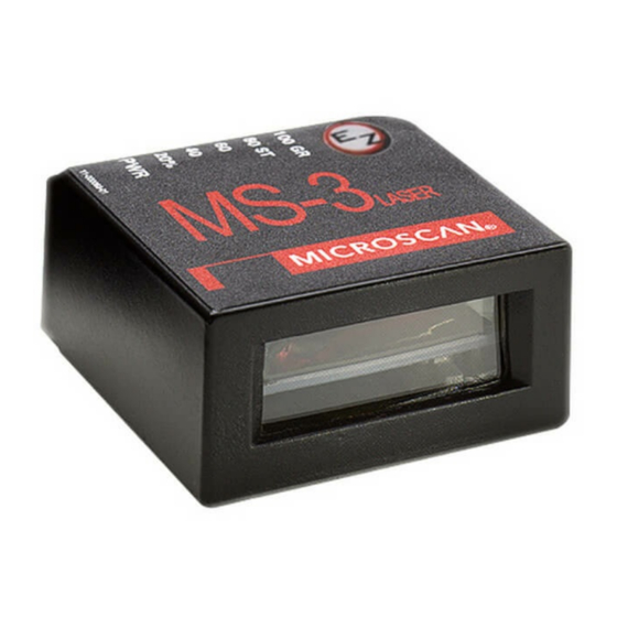
About the MS-3 Laser Scanner The MS-3 Laser is a ultra-compact scanner that can decode high density symbols from 2 to 10 inches at a 70 degrees scan angle with scan rates of 300 to 1000 decodes per second with a low power draw of 300mA at 5V. A multi-function... -
Page 10: Product Labels
Product Labels The following labels are located on the top, side, and bottom of the MS-3 Reader: MS-3 LASER Side Bottom Approvals This equipment is in compliance or approved by the following organizations: • CDRH (Center for Devices & Radiological Health) •... -
Page 11: Warning And Caution Summary
Systems warranty and could expose the user to laser diode power of up to 7 mW. WARNING The laser beam can be harmful to eyesight. Avoid eye contact with the laser beam. Never point the beam at other people, or in a direction where people may be passing. MS-3 Laser Scanner User’s Manual... - Page 12 MS-3 Laser Scanner User’s Manual...
- Page 13 Note: You can learn the current setting of any parameter by inserting a question mark after the number, as in <K100?> To see all “K” commands, send <K?>. MS-3 Laser Scanner User’s Manual...
-
Page 14: Step 1 Hardware Required
5VDC. Incorrect wiring or voltage can cause software or equipment fail- ures. If connecting to a host with an ADP Interface Box, you will need the following: • (1) An MS-3 laser scanner. • (2) An ADP-232 interface box P/N 99-510007-01. -
Page 15: Step 2 Connect The System
5 VDC input 2. If using your own null modem RS232 host cable, be certain that the host’s TxD connects to the scanner’s RxD and the scanner’s TxD connects to the host’s RxD. MS-3 Laser Scanner User’s Manual... -
Page 16: Step 3 Initiate Communications
In order to communicate with the scanner, you will need to use the following commu- nications settings: Baud = 9600 Parity = Even Stop Bits = Data Bits = Seven Flow Control = None Figure 1-3 Hyperterminal Dialog MS-3 Laser Scanner User’s Manual... -
Page 17: Step 4 Position Symbol And Scanner
High Density Scan Width Scan angle typically Scan angle Range 70 degrees typically 70 degrees Range Figure 1-4 Low Density Ranges Figure 1-5 High Density Ranges 1. Consult Table A-1, “FIS Numbers,” on page A-3. MS-3 Laser Scanner User’s Manual... -
Page 18: Step 5 Start Calibration
TEST LEDs turn amber to indicate that Read rate the calibration is in progress. 100% performance LEDs 2. End calibration: The test will end automatically when the optimum combination of settings has been achieved. 11-000063-01 MS-3 Laser Scanner User’s Manual... -
Page 19: Step 6 Test For Read Rate
By Test Button Press and hold the TEST button on the MS-3 until you hear beep and see LED momentarily turn amber. This will signal the beginning of the read rate routine. 3. Observe read rate performance... -
Page 20: Step 7 Save Settings
Step 7 — Save Settings After calibrating the MS-3, you can save your new settings to be available on power-on by: By Serial Command Send <Z> from your terminal. By Test Button Press and hold the TEST button Test Button... -
Page 21: Chapter 2 Communications
Data Bits = Seven Flow Control = None Note: You can learn the current setting of any parameter by inserting a question mark after the number, as in <K100?> To see all “K” commands, send <K?>. MS-3 Laser Scanner User’s Manual... - Page 22 Communications By Serial Command Command Title Format Host Port Parameters <K100,baud,parity,stop bits,data bits> RS422 Status <K102,status> <K101,aux port mode,baud,parity,stop bits,data Auxiliary Port Parameters bits,daisy chain status,daisy chain ID> MS-3 Laser Scanner User’s Manual...
- Page 23 Chapter 2 Communications Communications by Embedded Menu Microscan’s scanners have embedded menus that can be accessed from the terminal window in ESP or from a separate terminal program. See “Embedded Menus” on page A-22 for instructions on using the embedded menus.
-
Page 24: Host Port Parameters
Data Bits, Host Port Definition: Number of bits in each character. Usage: Only changed if necessary to match host setting. Serial Cmd: <K100, baud rate,parity,stop bits,data bits> Default: Seven Options: 0 = Seven 1 = Eight MS-3 Laser Scanner User’s Manual... -
Page 25: Rs422 Status
Whenever RS422 is disabled, RS232 is enabled in the background. However, when Multidrop is enabled, the functioning protocol is RS485 regardless of the displayed status of RS422. Before enabling RS422, first double-check that Multidrop is not enabled. MS-3 Laser Scanner User’s Manual... -
Page 26: Auxiliary Port
<K101,aux port mode,baud rate,parity,stop bits,data bits,daisy chain ID status,daisy chain ID> Default: Disabled Options: 0 = Disabled 1 = Transparent 2 = Half duplex 3 = Full duplex 4 = Daisy chain 5 = Command Processing MS-3 Laser Scanner User’s Manual... - Page 27 A common application, in conjunction with handheld scanners, is one that employs an auxiliary readout to detect mis-applied bar code sym- bols. Serial Cmd: <K101,aux port mode,baud rate,parity,stop bits,data bits,daisy chain ID status,daisy chain ID> 1 = Transparent MS-3 Laser Scanner User’s Manual...
- Page 28 Usage: Useful when the user wants bar code data displayed on an auxiliary screen close to the scanner. Serial Cmd: <K101,aux port mode,baud rate,parity,stop bits,data bits,daisy chain ID status,daisy chain ID> 2 = Half Duplex MS-3 Laser Scanner User’s Manual...
-
Page 29: Full Duplex Mode
• All host data is echoed to the auxiliary port in Host Port unpolled mode. Scanner Usage: When communication to and from the auxiliary port is required. Serial Cmd: <K101,aux port mode,baud rate,parity,stop bits,data bits,daisy chain ID status,daisy chain ID> 3 = Full duplex MS-3 Laser Scanner User’s Manual... -
Page 30: Daisy Chain Mode
The above example is based on the best case. Other factors such as baud rate, dynamic focus timing, number of characters in a given symbol, and the number of slaves in the daisy chain can affect timing and may need to be included in your calculations for complete accuracy. MS-3 Laser Scanner User’s Manual 2-10... - Page 31 9. All but the master scanner must have their diagnostic warning mes- sages disabled. 10. Daisy Chain ID Status enable/disable and the number of charac- ters in Daisy Chain ID must be the same in all scanners. MS-3 Laser Scanner User’s Manual 2-11...
- Page 32 ID status,daisy chain ID> Default: 9600 Options: 0 = 600 3 = 4800 6 = 38.4K 1 = 1200 4 = 9600 7 = 57.6K 2 = 2400 5 = 19.2 K 8 = 115.2 K MS-3 Laser Scanner User’s Manual 2-12...
- Page 33 Number of bits in each character. Usage: Only changed if necessary to match host setting. Serial Cmd: <K101, aux port mode,baud rate,parity,stop bits,data bits,daisy chain ID status,daisy chain ID> Default: Seven Options: 0 = Seven 1 = Eight MS-3 Laser Scanner User’s Manual 2-13...
- Page 34 Used in a daisy chain setup in cases where the host needs to know which scanner sent the data. Serial Cmd: <K101, aux port mode,baud rate,parity,stop bits,data bits,daisy chain status,daisy chain ID> Default: Options: Any one or two ASCII characters. MS-3 Laser Scanner User’s Manual 2-14...
- Page 35 ESP or serial commands. Note: You can learn the current setting of any parameter by inserting a question mark after the number, as in <K100?> To see all “K” commands, send <K?>. MS-3 Laser Scanner User’s Manual...
- Page 36 Protocol By Serial Command Command Title Format Host Protocol <K140,protocol> <K145,status> Response Timeout <K143,response timeout> Intercharacter Delay <K144,intercharacter delay> Preamble <K141,preambole status,preamble> Postamble <K142,postamble status,postamble> MS-3 Laser Scanner User’s Manual...
-
Page 37: Chapter 3 Protocol
Chapter 3 Protocol Protocol by Embedded Menu For information on accessing the embedded menus, see “Embedded Menus” on page A-22. From the Main menu, scroll down through the options and select the following screen: MS-3 Laser Scanner User’s Manual... -
Page 38: Protocol
Point-to-Point (standard) Definition: Standard Point-to-Point requires no address and sends data to the host whenever it is available, without any request or handshake from the host. Usage: Used only with RS232 or RS422. Serial Cmd: <K140,0> MS-3 Laser Scanner User’s Manual... - Page 39 Used only with RS232. Serial Cmd: <K140, 2> Point-to-Point with RTS/CTS & XON/XOFF Definition: This option is a combination of Point-to-Point with RTS/CTS and Point-to-Point with XON/XOFF. Usage: Used only with RS232. Serial Cmd: <K140,3> MS-3 Laser Scanner User’s Manual...
- Page 40 Serial Cmd: If selecting Multidrop fan address must be defined and appended to the command string. Format: <K100,5,address[01 to 50]> Note: Scanners linking up to a Microscan MS-5000 multidrop concentrator must be configured in standard multidrop protocol. User Defined Point-to-Point Definition: User Defined Point-to-Point allows the user to customize the point- to-point protocol.
- Page 41 If From Host is disabled, the defined protocol is not included. If From Host is enabled, the defined protocol must be included. Serial Cmd: <K140,6,RES,address,REQ,EOT,STX,ETX,ACK,NAK,from host> Default: Disabled Options: 0 = Disabled 1 = Enabled MS-3 Laser Scanner User’s Manual...
- Page 42 Note: Typically, parameters in User Defined Multidrop are defined by first enabling Multidrop, then enabling User Defined Multidrop. This pre-loads multidrop charac- ters into the parameters. Then changes are made to individual characters to match the host or other requirements. MS-3 Laser Scanner User’s Manual...
-
Page 43: Lrc
The extra LRC character is then appended to the transmission and the receiver (usually the host) performs the same addition and compares the results. Usage: Used when extra data integrity is required. Serial Cmd: <K145,status> Default: Disabled Options: 0 = Disabled 1 = Enabled MS-3 Laser Scanner User’s Manual... -
Page 44: Response Timeout
The scanner can be set to wait indefinitely by setting Response Timeout to zero. Serial Cmd: <K143,response timeout> Default: (causes an indefinite wait.) Options: 0 to 65000 (0 to 65 seconds) MS-3 Laser Scanner User’s Manual 3-10... -
Page 45: Intercharacter Delay
For example, a 200 setting will result in a 1/5 second delay between each character that is transmitted. Serial Cmd: <K144, intercharacter delay> Default: Options: 0 to 255 (in milliseconds). Zero (0) causes no delay between characters. MS-3 Laser Scanner User’s Manual 3-11... -
Page 46: Preamble Characters
(with the space key). This has the effect of allowing the con- trol key to be recognized as a part of the control character. Next hold down the control key while typing the desired character. Example: Space CNTL-m to enter ^M. MS-3 Laser Scanner User’s Manual 3-12... -
Page 47: Postamble Characters
(with the space key). This has the effect of allowing the con- trol key to be recognized as a part of the control character. Next hold down the control key while typing the desired character. Example: Space CNTL-m Space CNTL-j to enter ^M^J. MS-3 Laser Scanner User’s Manual 3-13... - Page 48 Postamble Characters MS-3 Laser Scanner User’s Manual 3-14...
- Page 49 ESP or serial commands. Note: You can learn the current setting of any parameter by inserting a question mark after the number, as in <K100?> To see all “K” commands, send <K?>. MS-3 Laser Scanner User’s Manual...
- Page 50 Start Serial Trigger Character <K229,start trigger character> End Serial Trigger Character <K230,end trigger character> Good Decode Reads <K221,decodes before output,consecutive status> End of Read Cycle <K220,end of read cycle,timeout duration> Multisymbol <K222,number of symbols,multisymbol separator> MS-3 Laser Scanner User’s Manual...
-
Page 51: Chapter 4 Read Cycle/Trigger
Chapter 4 Read Cycle/Trigger Read Cycle by Embedded Menu For information on accessing the embedded menus, see “Embedded Menus” on page A-22. From the Main menu, scroll down through the options and select the following screen: MS-3 Laser Scanner User’s Manual... -
Page 52: Trigger Mode
When To Output and Noread options have no affect on Continuous Read. Usage: Continuous Read is useful in testing symbol readability or scanner functions. It is not recommended for normal operations. Serial Cmd: <K200, 0> MS-3 Laser Scanner User’s Manual... - Page 53 Note: If Trigger is set to Continuous Read 1 Output, Number of Symbols will default back to 1 (if set to any number greater than 1). MS-3 Laser Scanner User’s Manual...
-
Page 54: Figure 4-1 Trigger Level
Rising edge is the trigger signal associated with the appearance of an object. Falling edge is the trigger signal associated with the subsequent disappearance of the object MS-3 Laser Scanner User’s Manual... -
Page 55: Figure 4-2 Trigger Edge
Rising edge is the trigger signal associated with the appearance of an object. Falling edge is the trigger signal associated with the subsequent disappearance of the object. MS-3 Laser Scanner User’s Manual... - Page 56 An auxiliary terminal can be connected to the aux port so the user can send the serial trigger character through the scanner to the host. Serial Cmd: <K200,5> MS-3 Laser Scanner User’s Manual...
-
Page 57: Trigger Filter Duration
Usage: Trigger Filter Duration is useful where trigger bounce could cause false triggers. Serial Cmd: <K200, trigger mode,trigger filter duration> Default: 244(10mS) Options: 2 to 65535 (corresponding to 82 µS to 2.68S in 40.9µS steps) MS-3 Laser Scanner User’s Manual... -
Page 58: External Trigger State
Determines whether a positive or negative transition will initiate the read cycle. Usage: Users can select the trigger polarity that will operate with their sys- tems. (If using the Microscan object detector, use Positive.) Serial Cmd: <K202, external trigger state>... -
Page 59: Serial Trigger Character
Control characters entered on the command line are displayed in the menu as mnemonic characters. Note: Serial Data or Serial Data or Edge triggering mode must be enabled for Serial Trigger Character to take effect. MS-3 Laser Scanner User’s Manual 4-11... - Page 60 Options: Two hex digits representing an ASCII character except <, >, XON and XOFF. Note: Serial Data or Serial Data or Edge triggering mode must be enabled for Serial Trigger Character to take effect. MS-3 Laser Scanner User’s Manual 4-12...
- Page 61 Options: Two hex digits representing an ASCII character except <, >, XON and XOFF. Note: Serial Data or Serial Data or Edge triggering mode must be enabled for Serial Trigger Character to take effect. MS-3 Laser Scanner User’s Manual 4-13...
-
Page 62: Good Decode Reads
Usage: Useful when the highest level of reliability is required. Serial Cmd: <K221, decodes before output,consecutive status> Default: Non-consecutive Options: 0 = Non-consecutive 1 = Consecutive MS-3 Laser Scanner User’s Manual 4-14... -
Page 63: Read Cycle
With External Level enabled, the read cycle does not end until the fall- ing edge trigger or a timeout occurs. The next read cycle does not begin until the next rising edge trigger. MS-3 Laser Scanner User’s Manual 4-15... - Page 64 (whichever occurs first) ends the read cycle. Usage: Useful in applications that require an alternative way to end the read cycle. For example, if an assembly line should stop completely or the intervals between objects are highly irregular. MS-3 Laser Scanner User’s Manual 4-16...
- Page 65 0 to 65535. (Divide any positive number entered by 100 to determine the time in seconds.) Note: A minimum setting of 2 is recommended. Note: Timeout or Timeout or New Trigger under End of Read Cycle must be enabled for Timeout Duration to take effect. MS-3 Laser Scanner User’s Manual 4-17...
-
Page 66: Multisymbol
LRC. Number of Symbols Definition: Number of Symbols is the number of different symbols that can be read in a single read cycle. Serial Cmd: <K222, number of symbols,multisymbol separator> Default: MS-3 Laser Scanner User’s Manual 4-18... - Page 67 Note: If Multisymbol Separator has been changed to any character other than the default comma and you wish to re-define the separator as a comma, use the embedded menu. Default: (comma) Options: Any available ASCII character, except < > NUL. MS-3 Laser Scanner User’s Manual 4-19...
- Page 68 Multisymbol MS-3 Laser Scanner User’s Manual 4-20...
- Page 69 To see all “K” commands, send <K?>. 1. If using an I 2/5 symbol, verify that the number of characters in the symbol being scanned matches the code length enabled for the I 2/5 symbol type (default is 10 and 6). MS-3 Laser Scanner User’s Manual...
- Page 70 Symbology by Embedded Menu From the Main menu, scroll down through the options until you reach the following screens: Code Type 1, Code Type 2, and Code Parameters, respectively. MS-3 Laser Scanner User’s Manual...
-
Page 71: Chapter 5 Symbology
<K474,status,fixed symbol length status,symbol length...> <K474,,,,UCC/EAN-128 status,output format,application record separa- UCC/EAN-128 tor status,application record separator character,application record brackets,application record padding> Code 93 <K475,status,fixed code length status,fixed code length> <K477,fixed bar length status,fixed bar length,min. no. of bars,bar Pharmacode widths,forward/reverse> MS-3 Laser Scanner User’s Manual... -
Page 72: Autodiscriminate
<S> Enable I 2/5 only Note: If using an I 2/5 symbol, verify that the number of characters in the symbol being scanned matches the symbol length enabled for the I 2/5 symbol type (default is 10 and 6). MS-3 Laser Scanner User’s Manual... -
Page 73: Narrow Margins
Serial Cmd: <K450,narrow margins status,symbology id status> Default: Disabled Options: 0 = Disabled 1 = Enabled Note: Do not use Narrow Margins with Large Intercharacter Gap enabled in Code 39 or Codabar. MS-3 Laser Scanner User’s Manual... -
Page 74: Symbology Id
Code 39 symbol with Check Digit and Check Digit Out- put enabled and Full ASCII conversion performed. For Other Codes • For Code 128, a indicates ECC/EAN-128; otherwise the modifier is a 0. • For all other codes, the modifier is 0. MS-3 Laser Scanner User’s Manual... -
Page 75: Background Color
If the background is darker than the symbol, then enable black back- ground. Typically the background is white; but on PCBs for example, they can be black. Serial Cmd: <K451, background color> Default: White Options: 0 = White 1 = Black MS-3 Laser Scanner User’s Manual... -
Page 76: Code 39
Check digit Output, added to the symbol, provides additional security. Serial Cmd: <K470, status,check digit status,check digit output,large intercharac- ter gap,fixed symbol length status,fixed symbol length,full ASCII set> Default: Disabled Options: 0 = Disabled 1 = Enabled MS-3 Laser Scanner User’s Manual... - Page 77 Fixed symbol Length helps prevent truncations and increases data integrity by ensuring that only one symbol length will be accepted. Serial Cmd: <K470, status,check digit status,check digit output,large intercharacter gap,fixed symbol length status,fixed symbol length,full ASCII set> Default: MS-3 Laser Scanner User’s Manual...
- Page 78 Since Full ASCII Set requires two code words to encode one character, it is less efficient. Serial Cmd: <K470,status,check digit status,check digit output,large intercharacter gap,fixed code length status,fixed code length,full ASCII set> Default: Disabled Options: 0 = Disabled 1 = Enabled MS-3 Laser Scanner User’s Manual 5-10...
-
Page 79: Codabar
Used to verify matching. Serial Cmd: <K471, status,start & stop match,start & stop match output,large intercharacter gap,fixed symbol length status,fixed symbol length,check digit type,check digit output> Default: Enabled Options: 0 = Disabled 1 = Enabled MS-3 Laser Scanner User’s Manual 5-11... - Page 80 Serial Cmd: <K471, status,start & stop match,start & stop match output,large intercharacter gap,fixed symbol length status,fixed symbol length,check digit type,check digit output> Default: Options: 1 to 64 MS-3 Laser Scanner User’s Manual 5-12...
- Page 81 For additional security a check digit can be added to the symbol. Serial Cmd: <K471, status,start & stop match,start & stop match output,large intercharacter gap,fixed symbol length status,fixed symbol length,check digit type,check digit output> Default: Disabled Options: 0 = Disabled 1 = Enabled MS-3 Laser Scanner User’s Manual 5-13...
-
Page 82: Interleaved 2 Of 5
It is typically not used but can be enabled for additional security in applications where the host requires redundant check digit verification. Serial Cmd: <K472,status,check digit status,check digit output,symbol length #1,symbol length #2> Default: Disabled Options: 0 = Disabled 1 = Enabled MS-3 Laser Scanner User’s Manual 5-14... - Page 83 10 characters plus a check digit, then enable Symbol Length for 12. Note: Typically, when printing an I 2/5 symbol with an odd number of digits, a 0 will be added as the first character. MS-3 Laser Scanner User’s Manual 5-15...
- Page 84 10 characters plus a check digit, then enable Symbol Length for 12. Note: Typically, when printing an I 2/5 symbol with an odd number of digits, a 0 will be added as the first character. MS-3 Laser Scanner User’s Manual 5-16...
-
Page 85: Upc/Ean
Usage: Used primarily in POS application in the retail industry. It is commonly used with Microscan scanners in applications in combination with Matchcode when there is a need to verify that the right product is being placed in the right packaging. - Page 86 Enabled or Required. Usage: Allows user to distinguish between the main and Supplemental sym- bols. Serial Cmd: <K473, UPC status,EAN status,supplementals status,separator sta- tus,separator character,supplementals type> Default: Disabled Options: 0 = Disabled 1 = Enabled MS-3 Laser Scanner User’s Manual 5-18...
- Page 87 Both: Either 2 character or 5 character supplementals will be considered valid. 2 Char Only: Only two character supplementals will be considered valid. 5 Char Only: Only five character supplementals will be considered valid. MS-3 Laser Scanner User’s Manual 5-19...
-
Page 88: Code 128
Serial Cmd: <K474, status,fixed symbol length status,fixed symbol length> Default: Options: 1 to 64 Note: Fixed Symbol Length Status must be enabled for Fixed Symbol Length to take effect. MS-3 Laser Scanner User’s Manual 5-20... -
Page 89: Ucc/Ean-128
(zeros) for variable length fields. Note: If an illegal Application Record format is detected, the scanner will process it as a noread and output a noread message (if enabled). MS-3 Laser Scanner User’s Manual 5-21... - Page 90 ,,,UCC/EAN-128 status,output format,application record sepa- rator status,application record separator character,application record brackets,application record padding> Default: Disabled Options: 0 = Disabled 1 = Enabled Note: Output Format must be set to Application Record before this parameter can take effect. MS-3 Laser Scanner User’s Manual 5-22...
- Page 91 <K474,,,,UCC/EAN-128 status,output format,application record sepa- rator status,application record separator character,application record brackets,application record padding> Default: Disabled Options: 0 = Disabled 1 = Enabled Note: Output Format must be set to Application Record before this parameter can take effect. MS-3 Laser Scanner User’s Manual 5-23...
-
Page 92: Code 93
Fixed Code Length helps prevent truncations and increases data integrity by ensuring that only one symbol length will be accepted. Serial Cmd: <K475, status,fixed code length status,fixed code length> Default: Options: 1 to 64 MS-3 Laser Scanner User’s Manual 5-24... -
Page 93: Pharmacode
Default: Options: 5 to 16 Minimum Number of Bars (Pharmacode) Serial Cmd: <K477,status,fixed bar length status,fixed bar length,min. no. of bars,bar widths,forward/reverse> Default: Options: 5 to 16 MS-3 Laser Scanner User’s Manual 5-25... - Page 94 Forward/Reverse Decoding Direction (Pharmacode) Definition: Specifies the direction that a bar can be read. Serial Cmd: <K477,status,fixed bar length status,fixed bar length,min. no. of bars, bar widths,forward/reverse> Default: Forward Options: 0 = Forward 1 = Reverse MS-3 Laser Scanner User’s Manual 5-26...
- Page 95 ESP or serial commands. Note: You can learn the current setting of any parameter by inserting a question mark after the number, as in <K100?> To see all “K” commands, send <K?>. MS-3 Laser Scanner User’s Manual...
-
Page 96: Matchcode By Serial Command
Enter data to database <K231,master symbol number,master symbol data> Request all Master Symbol information <K231,?> Request Master Symbol information <K231,master symbol number?> Delete Master Symbol <K231, master symbol number,> (See also “Master Symbol Database” on page 6-11.) MS-3 Laser Scanner User’s Manual... -
Page 97: Chapter 6 Matchcode
Chapter 6 Matchcode Matchcode by Embedded Menu For information on accessing the embedded menus, see “Embedded Menus” on page A-22. From the Main menu, scroll down through the options and select the following screen: MS-3 Laser Scanner User’s Manual... -
Page 98: Overview Of Matchcode
For example, a manufacturer might sort a prod- uct based on dates that are embedded in the bar code. MS-3 Laser Scanner User’s Manual... -
Page 99: Using Master Symbols
(see “New Master Pin” on page 6- 14).Other Master Symbol Serial Commands See also “Master Symbol Database” on page 6-11 for more information details on entering, requesting, and deleting master symbols. MS-3 Laser Scanner User’s Manual... -
Page 100: Matchcode Type
Useful in tracking product serial numbers that increment or decrement sequentially. Serial Cmd: <K223, matchcode type,sequential matching,match start position, match length,wild card character,sequence on noread,sequence on mismatch> Default: Increment Options: 0 = Increment 1 = Decrement MS-3 Laser Scanner User’s Manual... -
Page 101: Match Length
Match Start Position is set for 2, only the 2nd through 7th characters (from left to right) will be compared. Serial Cmd: <K223, matchcode type,sequential matching,match start position, match length,wild card character,sequence on noread,sequence on mismatch> Default: Options: 1 to 50 MS-3 Laser Scanner User’s Manual... - Page 102 CR1, CR23, CR358, etc. Serial Cmd: <K223 , matchcode type,sequential matching,match start position, match length,wild card character,sequence on noread,sequence on mismatch> Default: (asterisk) Options: Any valid ASCII character MS-3 Laser Scanner User’s Manual...
-
Page 103: Sequence On Noread
007 (sequenced on noread) As an example of Sequence on Noread Disabled, consider the following series of decodes: Master sym- Decoded symbol Master symbol after decode noread 003 (not sequenced) noread 004 (not sequenced) noread 004 (not sequenced) MS-3 Laser Scanner User’s Manual... -
Page 104: Sequence On Mismatch
As an example of Sequence On Mismatch Disabled, consider the following decodes: Master sym- Decoded sym- Master symbol after decode 004 (sequenced because of previous match) 006 (sequenced because of previous match) 006 (not sequenced because of previous mismatch) MS-3 Laser Scanner User’s Manual 6-10... -
Page 105: Master Symbol Database
For example, to enter data for master symbol 9, after making certain that master symbol database size is enabled for 9 or more symbols (see “Master Symbol Database Size” on page 6-11), send <K231,9,data>. MS-3 Laser Scanner User’s Manual 6-11... -
Page 106: Table 6-1 Maximum Characters For Master Symbol Database
Returns all master symbols if no number is added before the question mark. Caution: Be sure to add the or you will delete the master symbol(s). Options: 1 to 10 MS-3 Laser Scanner User’s Manual 6-12... -
Page 107: Delete Master Symbol Data
Serial Cmd: <Gmaster symbol number> To store the next symbol scanned as master symbol #1 send: <G> or <G1>. For all symbols numbers except 1, the number must be included. Options: 1 to 10 MS-3 Laser Scanner User’s Manual 6-13... -
Page 108: New Master Pin
Number of Symbols is set to 3 and New Master Pin is then activated, at the end of the next read cycle, the decoded bar code symbols will be saved as master symbols 1, 2, and 3. MS-3 Laser Scanner User’s Manual 6-14... - Page 109 ESP or serial commands. Note: You can learn the current setting of any parameter by inserting a question mark after the number, as in <K100?> To see all “K” commands, send <K?>. MS-3 Laser Scanner User’s Manual...
- Page 110 <K500,scan speed> <K700,laser on/off status,laser framing status,laser on position,laser Laser Controls off position,laser power> Automatic Gain Control <K504,gain adjustment,AGC sampling,AGC min,AGC max> Transition Counter <K505,transition counter status,transition counter threshold> Bar Detection <K502,(not used),minimum symbol transitions,maximum element> MS-3 Laser Scanner User’s Manual...
-
Page 111: Chapter 7 Scanner Setup
Chapter 7 Scanner Setup Scanner Setup by Embedded Menu For information on accessing the embedded menus, see “Embedded Menus” on page A-22. From the Main menu, scroll down through the options and select the following screen: MS-3 Laser Scanner User’s Manual... -
Page 112: Scan Speed
Note: Scan beams move faster across symbols further out in the scan range since the moving beam is being projected from a spinning mirror. Serial Cmd: <K500,scan speed> Options: 300 to 1000 Default: (x 10) MS-3 Laser Scanner User’s Manual... -
Page 113: Laser On/Off Status
Serial Cmd: <K700, laser on/off status,laser framing status,laser on posi- tion,laser off position,laser power> Default: Disabled Options: 0 = Disabled 1 = Enabled MS-3 Laser Scanner User’s Manual... -
Page 114: Laser Framing
Note: Because scan widths are not always perfectly symmetrical, the most effective way to setup laser framing is to experiment with the Laser On Position and Laser Off Position commands until you get the best results. MS-3 Laser Scanner User’s Manual... -
Page 115: Figure 7-1 Laser On Position
70 percent of the scan, as specified by this command. Figure 7-1 Laser On Position Serial Cmd: <K700, laser on/off status,laser framing status,laser on posi- tion,laser off position,laser power> Default: Options: 1 to 70 MS-3 Laser Scanner User’s Manual... -
Page 116: Figure 7-2 Laser Off Position
Laser On Position for an actual laser scan to take place. Figure 7-2 Laser Off Position Serial Cmd: <K700, laser on/off status,laser framing status,laser on position,laser position,laser power> Default: Options: 20 to 100 MS-3 Laser Scanner User’s Manual... -
Page 117: Laser Power
Allows the user or calibration routine to select laser power setting. Serial Cmd: <K700, laser on/off status,laser framing status,laser on position,laser position,laser power> Default: Medium Options: 0 = Low 1 = Medium 2 = High MS-3 Laser Scanner User’s Manual... -
Page 118: Automatic Gain Control
Gain command (“Gain Adjustment” on page 6- Usage: Disabled is not recommended, but can be useful in certain applications in which labels do not require a large depth of field. MS-3 Laser Scanner User’s Manual 7-10... - Page 119 <K504?> for a readout. AGC Maximum (Read Only) Definition: Limits the hardware gain available to the software for the usable range. Serial Cmd: <K504, gain adjustment,AGC sampling,AGC min,AGC max> Send <K504?> for a readout. MS-3 Laser Scanner User’s Manual 7-11...
-
Page 120: Transition Counter
AGC can be resolved. Usage: Can be useful in certain application where extraneous objects in the field of view might require a higher threshold. Serial Cmd: <K505, transition counter status,transition counter threshold> Default: Options: 0 to 255 MS-3 Laser Scanner User’s Manual 7-12... -
Page 121: Bar Detection
(default to white). Usage: Caution: Do not change this parameter unless instructed by a Micros- can representative. Serial Cmd: <K502,(not used),minimum symbol transitions,maximum element> Default: 1500 (45.75µS) Options: 1 to 65535 (.035µS to 2294µS increments) MS-3 Laser Scanner User’s Manual 7-13... - Page 122 Bar Detection MS-3 Laser Scanner User’s Manual 7-14...
- Page 123 ESP or serial commands. Note: You can learn the current setting of any parameter by inserting a question mark after the number, as in <K100?> To see all “K” commands, send <K?>. MS-3 Laser Scanner User’s Manual...
- Page 124 No Symbol Message <K716,no symbol status,no symbol message <K701,serial command echo status,serial command beep sta- Serial Verification tus,control/hex output> Quality Output <K704,quality output separator,reads/trigger status> Partial Output <K703,partial output status,start postion,length> Beeper Output <K702,beeper output> MS-3 Laser Scanner User’s Manual...
- Page 125 Chapter 8 Data Outputs Output Conditions by Embedded Menus For information on accessing the embedded menus, see “Embedded Menus” on page A-22. From the Main menu, scroll down through the options and select the following screen: MS-3 Laser Scanner User’s Manual...
-
Page 126: Symbol Output
When set to Match, the scanner transmits symbol data whenever a symbol matches a master symbol. However, if Matchcode Type is Dis- abled, it transmits on any good read. Note: A noread can still be transmitted if Enabled. MS-3 Laser Scanner User’s Manual... - Page 127 This command allows the user to choose when symbol data can be sent to the host. Serial Cmd: <K705,symbol output status,when to output> Default: As Soon As Possible Options: 0 = As Soon As Possible 1 = End of Read Cycle MS-3 Laser Scanner User’s Manual...
-
Page 128: Figure 8-1 Read Cycle
Figure 8-1 Read Cycle Usage: End of Read Cycle is useful in timing-based systems in which the host is not ready to accept data at the time it is decoded. MS-3 Laser Scanner User’s Manual... -
Page 129: Message Output
Counter Threshold Bad Bar Code met? message (if enabled) Scanner Scanner sends the outputs the No Bar Code No Symbol message message (if enabled) (if enabled) End of read cycle Figure 8-2 Output Message Flow MS-3 Laser Scanner User’s Manual... -
Page 130: Noread Message
Note: Noread Message will only be transmitted if Symbol Output (“Symbol Output Status” on page 8-4) is set to Match, Mismatch or Good Read. Noread Message can be set to any ASCII characters except NULL <> (comma). MS-3 Laser Scanner User’s Manual... -
Page 131: Bad Symbol Message
The Bad Bar Code output is tied to the transition counter. If during a read cycle no symbol is decoded and the required setting for the Tran- sition Sample Threshold is met, a user defined message will be sent to the host. MS-3 Laser Scanner User’s Manual... -
Page 132: No Symbol Message
<K716,no symbol status,no symbol message> Default: Disabled Options: 0 = Disabled 1 = Enabled No Symbol Message Serial Cmd: <K716,no symbol status,no symbol message> Default: NOLABEL Options: Up to seven ASCII characters (except NUL) MS-3 Laser Scanner User’s Manual 8-10... -
Page 133: Serial Verification
However, this does not necessarily mean that all data fields have been entered incorrectly. Only one bad field needs to be found in order to activate the 5 beep response. Usage: Used to audibly verify the acceptance and validity of a command. MS-3 Laser Scanner User’s Manual 8-11... - Page 134 Usage: Useful when brackets are required to delineate certain scanner outputs such as counters. Serial Cmd: <K701,status> Default: Enabled Options: 0 = Disabled 1 = Enabled MS-3 Laser Scanner User’s Manual 8-12...
-
Page 135: Quality Output
ASCII character Note: For all serial configuration commands, the following characters cannot be used:, < > NUL Reads/Trigger Status Serial Cmd: K704,quality output separator,reads/trigger status> < Default: Disabled Options: 0 = Disabled 1 = Enabled MS-3 Laser Scanner User’s Manual 8-13... -
Page 136: Partial Output
<K703,partial output status,start postion,length> Default: Options: 1 to 63 Partial Length Definition: Allows you to determine the number of characters to be transmitted. Serial Cmd: <K703,partial output status,start postion,length> Default: Options: 1 to 63 MS-3 Laser Scanner User’s Manual 8-14... -
Page 137: Beeper Output
Can be used as an audible verification that either a good read or a noread has occurred. Beeper Output Condition Serial Cmd: <K702,beeper output> Default: On Good Options: 0 = Disabled 1 = On Good 2 = On Noread MS-3 Laser Scanner User’s Manual 8-15... - Page 138 Beeper Output MS-3 Laser Scanner User’s Manual 8-16...
-
Page 139: Chapter 9 Discrete I/O
ESP or serial commands. Note: You can learn the current setting of any parameter by inserting a question mark after the number, as in <K100?> To see all “K” commands, send <K?>. MS-3 Laser Scanner User’s Manual... - Page 140 Output Conditions by Serial Command Command Title Format Output 1 <K720,output on,polarity,pulse width,number to output on> Output 2 <K721,output on,polarity,pulse width,number to output on> Output 3 <K722,output on,polarity,pulse width,number to output on> MS-3 Laser Scanner User’s Manual...
- Page 141 Chapter 9 Discrete I/O Output Conditions by Embedded Menus For information on accessing the embedded menus, see “Embedded Menus” on page A-22. From the Main menu, scroll down through the options and select the following screen: MS-3 Laser Scanner User’s Manual...
-
Page 142: Output 3
Note: If you want to output for a good read and Matchcode is not enabled, you can enable any output for Match. Mismatch Definition: Activates a discrete output whenever the symbol data does not match that of the master symbol. MS-3 Laser Scanner User’s Manual... - Page 143 For example, if Number to Output On is set to 3 and Output 1 is set to Noread, then Output 1 will not be activated until 3 noreads have occurred. Serial Cmd: <K720, output on,polarity,pulse width,number to output on> Default: Options: 0 to 255 MS-3 Laser Scanner User’s Manual...
- Page 144 <K721,output on,polarity,pulse width,number to output on> Output 2 has the same parameters and default settings as Output 1. Output 3 Serial Cmd: <K722,output on,polarity,pulse width,number to output on> Output 3 has the same parameters and default settings as Output 1. MS-3 Laser Scanner User’s Manual...
- Page 145 ESP or serial commands. Note: You can learn the current setting of any parameter by inserting a question mark after the number, as in <K100?> To see all “K” commands, send <K?>. MS-3 Laser Scanner User’s Manual 10-1...
-
Page 146: Diagnostics By Serial Command
Command Title Format <K400,warning message status,laser high status,laser Warning Message Status low status,novram/reset warning status> Laser Overcurrent <K404,message> Laser Undercurrent <K405,message> Power-on/Resets Counts <K406,power-on count,resets> Time Since Last Reset <K407?> returns: hours,minutes (read only) MS-3 Laser Scanner User’s Manual 10-2... -
Page 147: Chapter 10 Diagnostics
Chapter 10 Diagnostics Diagnostics by Embedded Menu For information on accessing the embedded menus, see “Embedded Menus” on page A-22. From the Main menu, scroll down through the options and select the following screen: MS-3 Laser Scanner User’s Manual 10-3... - Page 148 These messages serve as a flag to service a scanner or as an early warning that potential problems could arise. They are particularly use- ful in factories that run 24/7 and can’t afford down time. MS-3 Laser Scanner User’s Manual 10-4...
-
Page 149: Warning Message Status
Alerts the user to impending failures or conditions that may soon cause failures. Serial Cmd: <K400,warning message status,laser high status,laser low status, novram/reset warning status> Default: Disabled Options: 0 = Disabled 1 = Enabled MS-3 Laser Scanner User’s Manual 10-5... -
Page 150: Laser High Warning
30 minutes until the condition is corrected. Laser High Status Definition: Enables the Laser High message. Usage: Alerts the user to impending laser failure. (Contact Microscan Service.) Serial Cmd: <K400,warning message status,laser high status,laser low status, novram/reset warning status>... -
Page 151: Laser Low Warning
30 minutes until the condition is corrected. Laser Low Status Definition: Enables the Laser Low message. Usage: Alerts the user to impending laser failure. (Contact Microscan Service.) Serial Cmd: <K400,warning message status,laser high status,laser low status, novram/reset warning status>... -
Page 152: Novram Corrupt Warning Status
If the condition persists, contact Microscan Service. <NVBAD-D> Indicates that diagnostic lifetime hours, power-on counts, and reset counts have been lost. The message repeats once every 30 minutes. (Contact Microscan Service.) <NVBAD-L> Indicates a problem with laser current factory reference. The message repeats once every 30 minutes. -
Page 153: Power-On Count
Usage: Useful for detecting unwanted resets caused by power supply problems or ESD transients. Serial Cmd: Send <K406?> Returns <K406 power-on count,resets> Read Only 0 to 65,535 powerups, 0 to 65,535 resets. Ranges: MS-3 Laser Scanner User’s Manual 10-9... -
Page 154: Time Since Last Reset
Usage: Useful as a troubleshooting tool that can help pinpoint the cause of a reset. Serial Cmd: Send <K407?> Returns <K407hours,minutes> Read Only 0 to 23 hours, 0 to 59 minutes. Ranges: MS-3 Laser Scanner User’s Manual 10-10... - Page 155 Note: The characters NULL <> can only be entered through embedded menus, not through ESP or serial commands. Note: Utility commands are not accessible by embedded menus. MS-3 Laser Scanner User’s Manual 11-1...
-
Page 156: Table 11-1 Summary Of Utility Serial Commands
<Ard> Reset and recall factory defaults <Arp> Reset and recall power-on parameters Default/Reset/Save <Arc> Recall and recall customer default parameters <Z> Save current settings for power-on <Zc> Save current settings as customer default parameters MS-3 Laser Scanner User’s Manual 11-2... - Page 157 Also <Mmaster symbol number,> <))> Delete Master Symbol # 1 <K225,status> Enable/disable New master pin Network <n> Network status Command Status <?> Scanner Status Status Requests <?1> Extended scanner status <K?> Configuration status MS-3 Laser Scanner User’s Manual 11-3...
-
Page 158: Counters
Mismatch Counter With Matchcode enabled, sending <X> displays the number of decoded symbols since the last reset that do not match the master symbol. Mismatch Counter Reset Sending <Y> sets the mismatch counter to zero. MS-3 Laser Scanner User’s Manual 11-4... -
Page 159: Part Number
<#> the scanner returns software part numbers for application code <#a/__________> and boot code <#b/_________>. Individual part numbers for Application Code and Boot Code are returned when their respective commands <#a> <#b> are sent. MS-3 Laser Scanner User’s Manual 11-5... -
Page 160: Checksum
4-digit hex numbers that are the check sums for boot code and the application code. Individual checksums for Boot Code and Application Code and Raster Code are returned when their respective commands <!b> <!a> are sent. MS-3 Laser Scanner User’s Manual 11-6... -
Page 161: Read Rate
(if any) for multiple symbols. End Read Rate Test Sending <J> ends both the Percent test and the Decodes/Second test for both single and multi-symbol. MS-3 Laser Scanner User’s Manual 11-7... -
Page 162: Device Control
Note: The spinning mirror reaches full speed after a short time delay. Motor Off Sending <KF> turns the spinning mirror motor off. This command is useful for long idle periods. Note: Laser turns off whenever motor is off. MS-3 Laser Scanner User’s Manual 11-8... - Page 163 <L3> pulses activates the link between Output 3(+) and Output 3 (–) of the host connector for the duration set by “Pulse Width” on page 8-18. (regardless of Master Symbol or Output 3 status). MS-3 Laser Scanner User’s Manual 11-9...
-
Page 164: Symbol Type
Code 39 symbols without changing scan- ner configuration. Sending <R> enables the scanner to decode Codabar symbols without changing scan- ner configuration. Sending <S> enables the scanner to decode I 2 of 5 symbols without changing scan- ner configuration. MS-3 Laser Scanner User’s Manual 11-10... -
Page 165: Defaulting/Saving/Resetting
By using the hardware default to default the power-on settings to the known factory defaults, the user can subsequently recall their previously customer saved settings with the <Arc> or <Zrc> commands. MS-3 Laser Scanner User’s Manual 11-11... - Page 166 Resets (“A” commands) affect only the current settings (active memory) and are not saved for power on or recall. Active Memory is where the reader’s active settings are stored during use. These are not available on power-on unless saved by a “Z” command. MS-3 Laser Scanner User’s Manual 11-12...
-
Page 167: Code Types Enable Commands
Enable Code 39 only <R> Enable Codabar only <S> Enable I 2/5 only Master Symbol Database Chapter 6, “Matchcode” for master symbol commands. “Master Symbol Database” on page 6-11 for master symbol database commands. MS-3 Laser Scanner User’s Manual 11-13... -
Page 168: Scanner Status Requests
2. Next, enter your binary values in Table 11-4 in the “Binary” column next to the appropriate bit. Table 11-3 Hex Value to Binary Table 11-4 MS-3 Laser Scanner Status Conversion Binary Scanner Status Binary Command error detected Command received... -
Page 169: Appendices
Appendix J Formulas for Number of Decodes ......... A-19 Appendix K Operational Tips..............A-21 Appendix L Embedded Menus ..............A-22 Appendix M Interface Standards .............. A-23 Appendix N Multidrop Communications ........... A-24 Appendix O Glossary of Terms ..............A-29 MS-3 Laser Scanner User’s Manual... -
Page 170: Appendix A General Specifications
Scan width angle: >70° Pitch: ±50° Skew: ±40° Symbol contrast: 25% min. @ 650nM Communication Figure A-1 MS-3 laser Dimensions RS232, RS422/485, Keyboard wedge, USB Connector 3 ft. (914mm) cable terminated with 15-pin D-Sub socket connector. Symbol Types Standard offering: Code 39, Code 93, Code 128, Codabar, Pharmacode, Interleaved 2 of 5,... -
Page 171: Table A-1 Fis Numbers
Product specifications are given for typical performance at 25°C (77°F) using grade A symbols. Some performance characteristics may vary at high temperatures or other environmental extremes. © Microscan Systems, Inc. Specifications subject to change.Electrical Specifications MS-3 Laser Scanner User’s Manual... -
Page 172: Appendix B Electrical Specifications
Trigger Inputs: 3 to 24V rated (10mA @24VDC) New Master: 3 to 24V rated (10mA @ 24VDC) Outputs (1, 2, 3): 5V TTL compatible Scanner Pin Assignments Table A-2 MS-3 Laser Host Connector, 15-pin Host Host & Aux Host RS232... -
Page 173: Appendix C Adp Interface Box
Transmit RS-232 (TTL) Receive RS-232 (TTL) Function Power/Signal ground Trigger Default configuration (NPN) + 5 VDC Trigger (NPN) + 12 VDC Chassis ground Power ground POWER RS-232 (J4) ADP-232 TRIGGER SCANNER Figure A-2 ADP RS-232 Interface Box MS-3 Laser Scanner User’s Manual... -
Page 174: Appendix D Serial Configuration Commands
<K231,master symbol number,master symbol data [no data will delete cur- Symbol Data rent master symbol data]> Request Master <K231,?>[for all] or <K231,master symbol number?> Symbol Data <K400,warning message status,laser high status,laser low status,novram/ Warning Message Status reset warning status> Lifetime Hours <K401,hours10,message> Over-temperature <K402,degrees,message> MS-3 Laser Scanner User’s Manual... - Page 175 <K508,focusposition,zero position> Beeper Output <K702,beeper output> Output 1 <K720, output on,polarity,pulse width,output mode,number to output on> Output 2 <K721, output on,polarity,pulse width,output mode,number to output on> Output 3 <K722,output on,polarity,pulse width,output mode,number to output on> MS-3 Laser Scanner User’s Manual...
-
Page 176: Appendix E Serial Command Format
For example, if only the last field in the following command is chang- ing, <K4,1,0,0> can be entered as <K,,,0>. • All fields following a modified field can be omitted. For example, to change Baud Rate, send <K3>. MS-3 Laser Scanner User’s Manual... - Page 177 While it appears that nothing has been assigned, the hex value 20 will be sent during data transmission. To Select NUL as the Character Press SP, then a (zero). It is displayed as <NUL> in the menu when the screen is refreshed. MS-3 Laser Scanner User’s Manual...
-
Page 178: Appendix F Ascii Table
Appendix F — ASCII Table Table A-8 ASCII Table with Control Characters Ctrl “ & < > MS-3 Laser Scanner User’s Manual A-10... -
Page 179: Table A-9 Communication Protocol Commands
Control Characters (Mnemonic displayed (Entered in menu or Effect of Command Code on Microscan menu) serial command) Reset Request Reset Start of Text End of Text Acknowledge Negative Acknowledge Begin Transmission XOFF Stop Transmission MS-3 Laser Scanner User’s Manual A-11... -
Page 180: Appendix G Defaulting/Saving/Resetting
By using the hardware default to default the power-on settings to the known factory default, the user can then recall their previously customer saved settings with the <Arc> or <Zrc> commands. MS-3 Laser Scanner User’s Manual A-12... - Page 181 Resets (“A” commands) affect only the current settings (active memory) and are not saved for power on or recall. Active Memory is where the reader’s active settings are stored during use. These are not available on power-on unless saved by a “Z” command. MS-3 Laser Scanner User’s Manual A-13...
- Page 182 Listen for a series of quick beeps, then short the default pins again. 4. You should hear a longer beep. If not, repeat the process. 1. There are no menu options or host commands for resetting the configuration program. MS-3 Laser Scanner User’s Manual A-14...
-
Page 183: Reader Status Requests
These represent, in order: the status byte as discussed above, the boot part number, application part number, fpga part number, Flash check- sum, and Flash parameter checksum. <K?> Configuration Command Status Returns the current status of all configuration commands. MS-3 Laser Scanner User’s Manual A-15... -
Page 184: Appendix H Symbol Configuration
Appendix H — Symbol Configuration You can configure your scanner by presenting Code 128 symbols that the MS-3 scan- ner responds to as serial commands. Note: Your scanner does not need to be enabled for Code 128 in order to enter symbol configuration. - Page 185 To end the read rate test and the symbol configuration program, scan this symbol: This will terminate symbol configuration mode. Changes made in configuration will remain in effect just as would changes made in the menus or by serial commands. MS-3 Laser Scanner User’s Manual A-17...
-
Page 186: Appendix I Object Detector
As the item continues to move down the line, its symbol moves into the reader beam and is read by the reader. Bar coded item Bar coded item Object MS-3 detector Figure A-1 Object Detector MS-3 Laser Scanner User’s Manual A-18... -
Page 187: Appendix J Formulas For Number Of Decodes
1. The -3 component in the formula is included to allow for AGC acquisition, an incomplete first scan, and an incomplete last scan. This applies only if the number inside the parentheses equals 4 or more. If the number equals 3, then only subtract 2 to derive 1 good scan. MS-3 Laser Scanner User’s Manual A-19... -
Page 188: Figure A-4 Angled Picket Fence
Increasing the height of a ladder symbol means it will receive more scans. Changing symbol density and/or symbol ratio is another way ranges, decode rates, etc. can be altered. MS-3 Laser Scanner User’s Manual A-20... -
Page 189: Appendix K Operational Tips
• Avoid excessive tilt, pitch, and skew of the symbol. • Check the symbol for readability by doing a decode rate test. If there is any ques- tion about the symbol's readability, contact your Microscan representative at helpdesk@microscan.com. • After changing any parameter that might affect decode rate, repeat decode rate test. -
Page 190: Appendix L Embedded Menus
Appendix L — Embedded Menus In addition to ESP, you can also use a communications menu such as Microsoft’s HyperTerminal to establish communication with Microscan’s embedded menus. 1. With your host connected to Quadrus EZ, set your host communications settings as follows: 9600... -
Page 191: Appendix M Interface Standards
With Microscan devices, selection of interface is made by pin assignment and, in the case of the host communications, by software switching between RS232 and RS422. -
Page 192: Appendix N Multidrop Communications
9. Your scanner is now in multidrop. From here on, you will need to use the concen- trator to relay commands and data between the scanner or scanners and the host. 10. Next, go to “Connect to Scanner via the Concentrator” on page A-52. MS-3 Laser Scanner User’s Manual A-24... - Page 193 If upload fails, return to the Serial Communication Parameters dialog and make the corrections. 8. Follow the same procedure for connecting other scanners to your multidrop network. Note: For more information, see your scanner user’s manual or Microscan’s MS-5000 Multidrop Concentrator User’s Manual, 83-005000.
-
Page 194: Figure A-5 Polling Sequence
REQ to the concentrator and request another response. If after three retries (the number of times it transmits a REQ to the con- centrator) the scanner receives no response, it ends the transmission with a RES (reset). MS-3 Laser Scanner User’s Manual A-26... -
Page 195: Figure A-6 Polling Sequence
If the scanner receives bad data from the concentrator, it transmits a SEL (its select address) and a NAK to the concentrator. The concentrator re-transmits the data up to three times. The concentrator will end the sequence with a RES (reset) if no ACK is received. MS-3 Laser Scanner User’s Manual A-27... - Page 196 Table A-13 Multidrop Addresses Poll Select Poll Select Multidrop Multidrop Character Character Character Character Address Address ASCII ASCII ASCII ASCII " & < > MS-3 Laser Scanner User’s Manual A-28...
-
Page 197: Appendix O Glossary Of Terms
Decode. A good read. The successful scanning and decoding of the information encoded in symbol. Default. Restore ROM or Flash settings, initialize serial commands and reset all counters. MS-3 Laser Scanner User’s Manual A-29... - Page 198 Host. A computer, PLC, or other device that is used to execute commands and pro- cess data and discrete signals. Host Port. The pins or connections on a scanner or other device that physically con- MS-3 Laser Scanner User’s Manual A-30...
- Page 199 Multisymbol. A scanner mode which allows a scanner to read more than one symbol in a single read cycle. Multidrop. A communications protocol for networking two or more scanners or other devices with a concentrator (or controller) and characterized by the use of individual MS-3 Laser Scanner User’s Manual A-31...
- Page 200 RAM. (Random Access Memory) Memory that is lost after power is recycled to the unit. MS-3 Laser Scanner User’s Manual A-32...
- Page 201 See “Daisy Chain.” Specular Reflection. The direct, mirror-like reflection of light back to the source causing saturation and bad reads. Supplemental. A character or data string that is appended to the main bar code symbol. MS-3 Laser Scanner User’s Manual A-33...
- Page 202 Watchdog Timer. A security device that detects system crashes and attempts to reset the scanner. Watchdog Reset. A reset that is forced whenever the software locks up. Wild Card. User-defined character entered into a master symbol to permit matches with variable characters. MS-3 Laser Scanner User’s Manual A-34...
Need help?
Do you have a question about the MS-3 and is the answer not in the manual?
Questions and answers