Table of Contents
Advertisement
Quick Links
Advertisement
Table of Contents

Related Manuals for Stratasys F120


Summary of Contents for Stratasys F120
- Page 1 F120 Shared Office 3D Printer USER GUIDE Part No. 405681-0001_REV_A...
- Page 2 Stratasys. This document may be printed for internal use only. All copies, shall contain a full copy of this copyright notice.
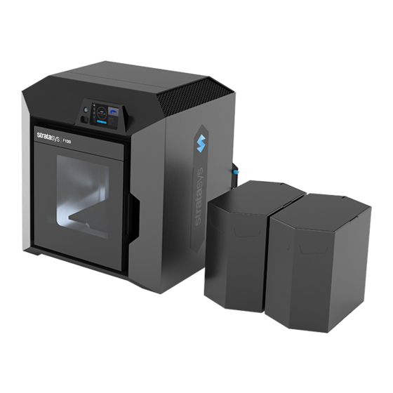
- Page 3 Direct Digital Manufacturing (DDM) allows for the creation of customized end- use parts straight from 3D CAD data. The F120 printers feature a servo/belt driven XY gantry with multiple modeling material capability.
- Page 4 • When you see text in blue, it indicates that the text is a linked reference to a specific figure, table, heading, or page number. • Standard bold text is used to emphasize items within instructional sequences or indicate a navigational path you must follow to locate/start a software application, open or save a file on your workstation PC, or perform an operation when working with GrabCAD Print.
-
Page 5: Table Of Contents
Connecting the Power Cable ......................... 11 Configuring the Network......................... 11 Installing GrabCAD Print ........................16 Connecting to the F120 Printer ......................16 Setting the Printer’s Date and Time ....................... 17 Updating the Controller software Version....................17 Adjusting the Tip Wipe Height ........................ 17 3 SYSTEM COMPONENTS .............. - Page 6 Print Heads ............................28 Materials Used ............................29 Material Coil Box Memory Chip......................30 Tips and Slice Height ..........................32 Controller Software ..........................33 GrabCAD Print Software ........................33 4 USER INTERFACE ................34 Navigation Menu ............................ 35 Display Area ............................36 Loading a File............................
- Page 7 5 OPERATING THE PRINTER ............. 95 Powering ON the Printer ........................95 Powering OFF the Printer ........................96 Material Coil Box Preparation ........................ 97 Connecting Material Coil Box To Printer....................98 Handling/Storing Materials ........................108 Replacing a Head..........................108 Before a Build............................110 Preparing the Printer ..........................
- Page 8 7 MAINTENANCE ................146 USB Flash Drive Method........................146 GrabCAD Print Method ........................149 USB Flash Drive Method........................149 GrabCAD Print Method ........................152 Cleaning the Oven Chamber........................ 154 Cleaning the Platen..........................154 Clean/Inspect Tip Wipe Assemblies ..................... 154 Cleaning the Exterior Surface of the Printer..................157 Cleaning the Touchscreen Display .......................
- Page 9 8 TROUBLESHOOTING ..............192 Warnings at Build Start......................... 193 Errors Preventing a Build from Starting....................194 Load/Unload Errors ..........................196 Build Pause Warnings .......................... 198 Build Abort Errors ..........................201 Head Warnings............................. 203 Head Errors............................203 9 SUPPLEMENTARY INFO ..............206 EMC Class A Warning ..........................
-
Page 10: Service And Support
Service Hazard Types 1 SERVICE AND SUPPORT This chapter provides information on service and support for the F120 as well as safety information and safety label locations. Service If you have a problem with your printer that is not covered in this guide, please contact Stratasys Customer Support. -
Page 11: Product Safety Signs
Stratasys makes every effort to ensure that our printers are safe and reliable at all times. However, there will be times when you must access areas of the printer where potentially high voltages, hot temperatures, and/or moving mechanical components could cause severe injury. -
Page 12: Product Safety Label Locations
Safety Instructions Product Safety Label Locations Product Safety Label Locations Figure 1: Oven safety label locations Figure 2: Rear panel safety label locations Page 3 © Copyright 2020 Stratasys. All rights reserved. -
Page 13: Potential Safety Hazard Areas
Oven Warning: Hot Surfaces. Always wear safety gloves and long sleeves when working inside the oven. Components are hot. Opening the oven door shuts the oven heaters off. Page 4 © Copyright 2020 Stratasys. All rights reserved. -
Page 14: Door Locks
Interlock switches are used to communicate the status of the oven door and the top cover to the printer. For safety reasons, the oven door and top cover must be closed before the X, Y, and Z motors will operate. Page 5 © Copyright 2020 Stratasys. All rights reserved. -
Page 15: General Safety Practices
Always wear safety gloves and long sleeves when working inside the oven. Components are hot. Environmental Requirements • The F120 printer is for indoor use only. • Air quality conditions with excessive solid particulates (conductive or non-conductive) may result in system damage. -
Page 16: Printer Setup
Description Welcome Insert Contains instructions for downloading the F120 User Guide (this document). Document This cable is used to establish a network connection between the F120 printer and your RJ45 Cable Ethernet network. See “Making the Network Connection” (page 10). - Page 17 Open the top cover and ensure that the orange clip has been removed from the X belt, and the orange tie wrap has been removed from the X motor. If not, remove the orange clip and/or orange tie wrap securing these components. Page 8 © Copyright 2020 Stratasys. All rights reserved.
- Page 18 Minimum 20 inches (50.8 cm) Left Side Clearance Minimum 4 inches (10.16 cm) Rear Clearance Minimum 6 inches (15.24 cm) Front Clearance Minimum 20 inches (50.80 cm) Overhead Clearance Minimum 20 inches (50.80 cm) Page 9 © Copyright 2020 Stratasys. All rights reserved.
-
Page 19: Identifying Your Printer
Model Tag Making the Network Connection Processed job files can be transferred from GrabCAD Print to the F120 printer through your facility’s Ethernet network. An RJ45 network connector is located on the right, rear corner of the printer (as viewed from the rear). See Figure 4 for the network connection location. -
Page 20: Connecting The Power Cable
A different IP address may be generated from time to time by the server or PC. • Wi-Fi address - the printer will scan for and allow you to connect to an available Wi-Fi network (if the Wi-Fi dongle has been installed). Page 11 © Copyright 2020 Stratasys. All rights reserved. - Page 21 If the Static option is enabled, you must manually configure the IP Address, Subnet Mask, and Gateway Address fields.To configure this information simply touch a field on the screen to select it and then use the keypad displayed to enter address information. Page 12 © Copyright 2020 Stratasys. All rights reserved.
- Page 22 PC; the generated IP address will be displayed within the IP Address field of the Network page, and corresponding Subnet Mask and Gateway Address information will also be displayed. Page 13 © Copyright 2020 Stratasys. All rights reserved.
- Page 23 Press the Scan button; the printer will scan for an available wireless (Wi-Fi) network. Figure 9: Scan for Wireless Network e. A list of available networks will be displayed; select the wireless network you’d like to connect to by pressing anywhere within the row. Page 14 © Copyright 2020 Stratasys. All rights reserved.
- Page 24 When finished, touch anywhere on the screen outside of the keypad to exit and close the keypad. h. Scroll to the bottom of the page and press the Connect button to save the network configuration. Figure 11: Connect Button Page 15 © Copyright 2020 Stratasys. All rights reserved.
-
Page 25: Installing Grabcad Print
While on the article/197-sign-up-download-and-install GrabCAD website, be sure to join the F120 User’s Group. Connecting to the F120 Printer Add the F120 printer to the GrabCAD Print application. Navigate to http://help.grabcad.com/ and follow the on-screen instructions. article/198-connect-your-printers Page 16 ©... -
Page 26: Setting The Printer's Date And Time
Update the Controller Software if necessary. See “Updating Controller Software” (page 146). Adjusting the Tip Wipe Height If necessary, adjust the tip wipe height. See “Tip Wipe Height Adjustment” (page 144). Page 17 © Copyright 2020 Stratasys. All rights reserved. -
Page 27: System Components
Printer Overview Access Doors and Panels 3 SYSTEM COMPONENTS This chapter describes the components of the F120 printer. Information regarding the materials and tips that can be used by the printer is also included in this chapter. Printer Overview Access Doors and Panels Do not energize when the rear panel is not secured in place. - Page 28 The printer’s camera is also housed within the oven door. Right & Left Side Panels The right and left side panels provide access to the oven chamber fans. Rear Panel The rear panel provides access to the electronics bay. Page 19 © Copyright 2020 Stratasys. All rights reserved.
-
Page 29: Interface Panel
The printer’s USB ports allow you to easily upload job files to be built. After plugging a USB flash drive into any of the USB ports you can access the flash drive’s contents via the Queue page (see “Working with the Queue Page” (page 45) for details). Page 20 © Copyright 2020 Stratasys. All rights reserved. -
Page 30: Oven Door
The oven door gasket, which runs around the perimeter of the oven door frame, helps to provide an airtight seal when the oven door is closed. The oven door window is composed of 2 panes of tempered glass. Page 21 © Copyright 2020 Stratasys. All rights reserved. - Page 31 Pictures are automatically taken at a set interval via GrabCAD Print. Please note that the camera image displayed will include some reflection as a result of the oven door’s glass. Figure 5: Camera Location Page 22 © Copyright 2020 Stratasys. All rights reserved.
-
Page 32: Oven Light
The Light button within the Tools page indicates the current state of the oven light and allows you to manually turn the light ON of OFF (see “Light” (page 94)). Figure 6: Oven Light Location Oven Light Page 23 © Copyright 2020 Stratasys. All rights reserved. -
Page 33: Platen
X and Y offset between model and support tips after either head has been replaced (during an automatic Tip Offset Calibration). Figure 7: Platen Components Tip Offset Calibration Targets Platen Page 24 © Copyright 2020 Stratasys. All rights reserved. -
Page 34: Tip Wipe Assemblies
Purged material debris is guided down from the tip wipe assemblies to the bottom of the oven chamber via the purge chute. Figure 8: Tip Wipe Assemblies Tip Wipe Assembly: Model = left Support = right Page 25 © Copyright 2020 Stratasys. All rights reserved. -
Page 35: Purge Chute
“Cleaning the Oven Chamber” (page 154) for instructions. Figure 9: Purge Chute Location Purge Chute Figure 10: Oven Chamber Cleaning Location Purged material debris will accumulate here Page 26 © Copyright 2020 Stratasys. All rights reserved. -
Page 36: Material Coil Box
The F120 printer uses a material coil box (Figure 11) to supply both model and support material to the printer. The material coil box is external to the F120 printer and must be manually loaded to one of the printer filament ports (Figure 11). -
Page 37: Print Heads
Assembly Print Heads The F120 printer utilizes one print head assembly for model and support material. The model and support heads are black. Once a head has been used for model or support, it can only be used for that designated material (model or support) thereafter. The heads are designed for use with a range of modeling materials. -
Page 38: Materials Used
Assembly Modeling Materials Materials Used The F120 printer can use a variety of model materials, in a range of colors. SR30 Soluble Release support material is used in conjunction with all model materials. See Table 3 (page 32) for model and support compatibility information. -
Page 39: Material Coil Box Memory Chip
Each material coil box has a memory chip; this memory chip recognizes the box’s material type and tracks the box’s volume. The F120 printer utilizes a different memory chip than other Stratasys materials and as a result, only F120 printer compatible material coil boxes can be used to build parts on the printer. - Page 40 A specific prompt will only be displayed if a material coil box volume related issue is detected. See “Warnings and Errors” (page 192) for details. Page 31 © Copyright 2020 Stratasys. All rights reserved.
-
Page 41: Tips And Slice Height
Tips and Slice Height Tips and Slice Height The F120 utilizes a T14 tip for all model and support materials. Tips are a component of the associated head assembly and cannot be changed individually. Instead, the entire head assembly is replaced as a single unit. -
Page 42: Controller Software
Controller Software is the software used to control the printer. GrabCAD Print Software The printer builds parts by processing an original CAD or STL file into a Stratasys CMB file which is then downloaded to the printer. GrabCAD Print is the software used to process files and then transfer them to the printer to be built. -
Page 43: User Interface
Overview 4 USER INTERFACE This chapter provides an overview of the F120 printer’s User Interface (UI). Specific printer operation information and procedures can be found in Chapter , 5 Operating the Printer (page 95). You must power ON the printer prior to using the touchscreen, see “Powering ON... -
Page 44: Navigation Menu
Table 1: Navigation Menu - Button States Button Selected Unselected Warning State Error State Name State State Build Button Unselected Selected Selected Unselected Queue Button Materials Button Selected Unselected Tools Button Page 35 © Copyright 2020 Stratasys. All rights reserved. -
Page 45: Display Area
(see Figure 4). Once all notifications have been corrected, press the Close button within the dialog to exit the dialog. Page 36 © Copyright 2020 Stratasys. All rights reserved. - Page 46 To access the Build page, press the Build button within the Navigation Menu; a screen similar to the one in Figure 3 will be displayed. Figure 3: Build Page Notifications display Print job Build information status panel display Print job controls Figure 4: Notification Details Page 37 © Copyright 2020 Stratasys. All rights reserved.
-
Page 47: Loading A File
To load a file: 1. Plug a USB flash drive into one of the available USB ports on the front of the printer (see Figure 3 (page 20) for USB port locations). Page 38 © Copyright 2020 Stratasys. All rights reserved. - Page 48 If a single flash drive is installed the job files located on the flash drive will be displayed in individual rows. Page 39 © Copyright 2020 Stratasys. All rights reserved.
- Page 49 7. Pressing the Print button within the Build page will initiate the build. Build progress will be displayed within the Build Status Display, see “Build Status Display” (page 42) for details. Figure 8: Build Page with Job Information Page 40 © Copyright 2020 Stratasys. All rights reserved.
-
Page 50: Viewing Print Job Information
Model and support materials associated with the job. Touching anywhere within this portion of the screen will open a page displaying additional details pertaining to the selected job (see “Viewing Job Details” (page 51)). Page 41 © Copyright 2020 Stratasys. All rights reserved. -
Page 51: Build Status Display
This indicates that the printer is in a state where it is ready to start a build. No progress is indicated within the outer build progress ring and the time remaining is displayed as zero. Figure 11: Build Status Display - Idle Page 42 © Copyright 2020 Stratasys. All rights reserved. - Page 52 Build Status Display will show the number of completed layers as compared to the total number of layers in the build. Touching the screen again, will toggle back to the time estimation information displayed initially. Page 43 © Copyright 2020 Stratasys. All rights reserved.
-
Page 53: Print Job Controls
(i.e. no substrate, etc.). See “Warnings at Build Start” (page 193) “Errors Preventing a Build from Starting” (page 194) for more information. Page 44 © Copyright 2020 Stratasys. All rights reserved. - Page 54 USB flash drive. Individual jobs are listed in numbered rows with row one corresponding to the first job in the Job Queue. Each row displays the name of the job, estimated build time Page 45 © Copyright 2020 Stratasys. All rights reserved.
-
Page 55: Adding A Job To The Job Queue
Adding a Job to the Job Queue The Job Queue is empty by default. To populate the Job Queue you must first load individual job files to the Job Queue using one of two methods: Page 46 © Copyright 2020 Stratasys. All rights reserved. - Page 56 3. Plug a USB flash drive into one of the available USB ports on the printer (see Figure 3 (page 20) for USB port locations). 4. Navigate to the Queue page by pressing the Queue button within the Navigation Menu. Page 47 © Copyright 2020 Stratasys. All rights reserved.
- Page 57 5. Press the Load File button in the upper-right corner of the touchscreen. Figure 15: Load File Button Location 6. The Load File page will be displayed; press the USB button within this page. Figure 16: Load File Page - USB Option Page 48 © Copyright 2020 Stratasys. All rights reserved.
- Page 58 Figure 17: Select File to Load 8. Within the Job Details page press the Add to Queue button; this will load the job into the Job Queue. Figure 18: Add File to Queue Page 49 © Copyright 2020 Stratasys. All rights reserved.
-
Page 59: Editing The Job Queue
Job Queue. Pressing the Back button will allow you to exit the Edit Queue page and return to the main Queue page. Figure 21: Edit Queue Page Queue Controls Page 50 © Copyright 2020 Stratasys. All rights reserved. -
Page 60: Viewing Job Details
Author: name of the user that submitted the job. • Materials: model and support materials associated with the job. • Layers: number of layers in the job. • Slice height: slice height associated with the job. Page 51 © Copyright 2020 Stratasys. All rights reserved. - Page 61 Press the Zoom Out button in the upper-right corner of the expanded view display to close the expanded view and return to the Job Details page. Figure 23: View Job Details - Expanded View Page 52 © Copyright 2020 Stratasys. All rights reserved.
-
Page 62: About The Sample Queue
Sample Queue, and therefore these job files cannot be deleted. • Jobs in the Sample Queue cannot be sorted (as described in “Editing the Job Queue” (page 50)). Page 53 © Copyright 2020 Stratasys. All rights reserved. - Page 63 After selecting any icons or opening a details page a "Back" button will be displayed within the heading of the page; press this button to return to the main Materials page. Page 54 © Copyright 2020 Stratasys. All rights reserved.
-
Page 64: Head Status Icons
Once temperature is reached, the tip will Loaded (solid blue) purge a small amount of material and the printer will begin building. Page 55 © Copyright 2020 Stratasys. All rights reserved. - Page 65 When the head’s odometer reaches 1350 build hours a warning will be displayed reminding you to order a Warning (head loaded) replacement head as the head is approaching is odometer limit. Page 56 © Copyright 2020 Stratasys. All rights reserved.
-
Page 66: Viewing Head Details
State: displays the load status of the corresponding head. • Last Material: displays the type of material last loaded to the head. • Date Loaded: displays the date that material was last loaded to the head. Page 57 © Copyright 2020 Stratasys. All rights reserved. - Page 67 Enable button has been pressed. After pressing the Maintenance button the button will toggle and instead display the Details button. Pressing the Details button will close the Head Maintenance page and return you to the Head Details page. Page 58 © Copyright 2020 Stratasys. All rights reserved.
- Page 68 Load Head button. A notification badge will be displayed within the button if any preconditions exist preventing the load/unload from occurring (see “Load/ Unload Errors” (page 196)). Page 59 © Copyright 2020 Stratasys. All rights reserved.
-
Page 69: Material Status Icons
Touching one of these icons on the screen, unless otherwise indicated in Table 7, will open that material’s Material Details page. Various graphics Page 60 © Copyright 2020 Stratasys. All rights reserved. - Page 70 User action required to replace the current material coil box with a valid one. See “Handling/Storing Materials” (page 108) “Connecting Material Coil Box To Printer” (page 98) for instructions. Invalid (red border) Page 61 © Copyright 2020 Stratasys. All rights reserved.
-
Page 71: Viewing Material Details
• Contact Customer Support or your regional Stratasys office if you experience this icon state (see “Getting Help”... - Page 72 The name of the type of material in the box is displayed at the bottom of the icon. To close this page and return to the main Materials page, press the Back button within the header of the page. Figure 29: View Material Details Warning/error information displayed here Page 63 © Copyright 2020 Stratasys. All rights reserved.
-
Page 73: Material Load Controls
Figure 30: Material Load Control Buttons Pressing the Load button initializes the load wizard. The load wizard instructs the user on the steps necessary to load material into the F120 (see “Loading Material” (page 97) for details). If the corresponding head is already loaded with material, the Load button will appear in its disabled state. - Page 74 Working with the Materials Page Material Load Controls Pressing the Unload initializes the unload wizard. The unload wizard instructs the user on the steps necessary to unload material from the F120 (see “Unloading Material” (page 105) details). Table 8: Material Load Control Buttons - Load Button States...
- Page 75 Material Status Icon and the corresponding Head Status Icon will be solid blue, the Head Status Icon will turn solid blue, and the Material Status Icon will display a blue Page 66 © Copyright 2020 Stratasys. All rights reserved.
- Page 76 The Load button will be displayed within the Material Details page once the filament has been completely retracted indicating that the material can be reloaded, if needed. Page 67 © Copyright 2020 Stratasys. All rights reserved.
- Page 77 Cancel button. In the event of a warning, text will be displayed on the screen to indicate the cause of the warning. Figure 33: Cancel Button Warning/error information will be displayed here Page 68 © Copyright 2020 Stratasys. All rights reserved.
- Page 78 To access the Tools page, press the Tools button within the Navigation Menu; a screen similar to the one in Figure 34 will be displayed. Figure 34: Tools Page Page 69 © Copyright 2020 Stratasys. All rights reserved.
-
Page 79: Tools Page Menu
ON and OFF. An indicator within the upper-left corner of the button displays the current state of the oven light (ON or OFF). See “Light” (page 94) Light for details. Page 70 © Copyright 2020 Stratasys. All rights reserved. -
Page 80: Navigation Overview
Back button in the upper-left corner of the page to exit the page. Figure 35: Settings Page Content List Page heading Back button Right arrow graphic Scrollbar Page 71 © Copyright 2020 Stratasys. All rights reserved. -
Page 81: Settings
After putting the printer into this state, you must send the processed job file to the Page 72 © Copyright 2020 Stratasys. All rights reserved. - Page 82 Job Queue upon completion of the build. The job’s file will need to be resent to the printer in order to be built again. Figure 39: Keep Previous Job Page 73 © Copyright 2020 Stratasys. All rights reserved.
- Page 83 (see Figure 42). The dialog will contain a graphic representing your printer’s platen as well as a blue bounding box graphic (the imaginary box surrounding the part). Page 74 © Copyright 2020 Stratasys. All rights reserved.
- Page 84 Figure 42: Part Placement Dialog First Layer Material The First Layer Material row displays the material type to be used for the first build layer, Model or Default. Figure 43: First Layer Material Page 75 © Copyright 2020 Stratasys. All rights reserved.
- Page 85 When the Energy Saver radio button is selected (i.e. Standby Mode is turned On) the printer’s oven will automatically shut off 2 hours after the completion of Page 76 © Copyright 2020 Stratasys. All rights reserved.
- Page 86 To configure this setting, press anywhere within the row; the Language page will be displayed. Use the scrollbar (along the right side of the page) to view the list of available languages. Select the radio button corresponding to your desired language. Page 77 © Copyright 2020 Stratasys. All rights reserved.
- Page 87 Within this page use the slider graphic to adjust brightness as needed. Sliding to the right will increase brightness while sliding to the left will dim brightness. Please note that you cannot set screen brightness to 0% (completely dim). Figure 52: Configure Screen Brightness Page 78 © Copyright 2020 Stratasys. All rights reserved.
- Page 88 Ethernet connection or through the use of a USB flash drive (see “Configuring the Network” (page 11) for details). Figure 55: Wifi Page 79 © Copyright 2020 Stratasys. All rights reserved.
- Page 89 To configure this setting, press anywhere within the row; the Camera page will be displayed. Use the radio buttons within the page to turn the setting On and Off as needed; On is selected by default. Figure 58: Configure Camera Page 80 © Copyright 2020 Stratasys. All rights reserved.
-
Page 90: Calibration
Calibrated will be displayed depending on the printer’s Calibration status. Pressing anywhere within the Tip Calibration row will open a page allowing you to select from a variety of tip calibration options. Figure 61: Tip Calibration Page 81 © Copyright 2020 Stratasys. All rights reserved. - Page 91 Touchscreen Calibration Pressing anywhere within the Touchscreen Calibration row will open a dialog allowing you to recalibrate the touchscreen display. See “Touchscreen Calibration” (page 141) for detailed instructions. Figure 63: Touchscreen Calibration Page 82 © Copyright 2020 Stratasys. All rights reserved.
-
Page 92: Maintenance
The single directional arrow button within the Gantry: section allows you to move the head in the X and Y axis. Pressing the Front Arrow button moves the head assembly to the front of the gantry. Page 83 © Copyright 2020 Stratasys. All rights reserved. - Page 93 Z positioning changes made using the directional arrow buttons. Figure 66: Gantry/Stage Page Chamber The Chamber row displays the current temperature as compared to the set point temperature of the oven chamber. Figure 67: Chamber Temperature Page 84 © Copyright 2020 Stratasys. All rights reserved.
- Page 94 “Updating Controller Software” (page 146) details). Figure 69: Update Controller Software Page System Odometers The System Odometers row displays the number of hours in which the printer has been building. Figure 70: System Odometers Page 85 © Copyright 2020 Stratasys. All rights reserved.
- Page 95 Figure 72: Open Source Licenses System Type The System Type row displays the printer’s model type information F120. Figure 73: System Type USB Tools Pressing anywhere within the USB Tools row will open a page allowing you to: •...
-
Page 96: Network
Pressing anywhere within the Connection Type row will allow you to select between a wired (Static or Dynamic) or wireless (Wi-Fi) network; Wired is selected by default. Use the Wired and Wireless radio buttons to select a connection type. After selecting a connection type press Page 87 © Copyright 2020 Stratasys. All rights reserved. - Page 97 Network page will vary. • If the Wired connection type is selected, the Network Mode row will be displayed. • If the Wireless connection type is selected, the Available Networks row will be displayed. Page 88 © Copyright 2020 Stratasys. All rights reserved.
- Page 98 Figure 78 (page 89) as a reference). Pressing anywhere within this row will open a page allowing you to scan for and connect to an available Wi-Fi network. After selecting an available Page 89 © Copyright 2020 Stratasys. All rights reserved.
- Page 99 Subnet Mask, Gateway Address, and MAC Address information will also be displayed. When finished, press the Back button to exit and return to the Tools page. Figure 81: Dynamic Network Configuration Page 90 © Copyright 2020 Stratasys. All rights reserved.
- Page 100 Press the Connect button to save the network information configured. Once the Connect button has been pressed and network information is saved, network information will not change. Page 91 © Copyright 2020 Stratasys. All rights reserved.
- Page 101 Press the Back button to exit the page and return to the Tools page. The Network button will refresh and a blue indicator will be displayed indicating that the printer is configured for a Wi-Fi network. Figure 84: Enter Network Settings Dialog Page 92 © Copyright 2020 Stratasys. All rights reserved.
-
Page 102: Power
Pressing the Yes button within this dialog will cause the printer to restart automatically. Press the Back button to exit the page and return to the Power page. Figure 87: Restart Confirmation Dialog Page 93 © Copyright 2020 Stratasys. All rights reserved. -
Page 103: Light
Oven light is ON. Selecting the Light button in this state will turn the oven light OFF. Oven light is OFF. Selecting the Light button in this state will turn the oven light ON. Page 94 © Copyright 2020 Stratasys. All rights reserved. -
Page 104: Operating The Printer
Basic User Operations Powering ON the Printer 5 OPERATING THE PRINTER This chapter explains basic steps in operating the F120 printer Basic User Operations Powering ON the Printer To power the printer ON: 1. Connect the male end of the supplied power cord directly into a grounded electrical outlet. -
Page 105: Powering Off The Printer
2. Press the power button located on the front of the printer (see Figure 1 for button location). 3. A dialog will be displayed asking you to confirm the power OFF; press Yes to power OFF. Figure 4: Power OFF Confirmation Page 96 © Copyright 2020 Stratasys. All rights reserved. -
Page 106: Material Coil Box Preparation
Two material coil boxes, one for model and one for support, must be connected to the F120 in order for it to build. -
Page 107: Connecting Material Coil Box To Printer
Pre-loading filament to the drive wheels places the filament into position to be loaded to the liquefier tip within the head. To connect and load material from a material coil box: Page 98 © Copyright 2020 Stratasys. All rights reserved. - Page 108 2. Select the Materials button from the Navigation Menu; a screen similar to Figure 6 (page 99) will be displayed. The information displayed represents the current configuration of your printer. Figure 6: Current Configuration - Load Material Page 99 © Copyright 2020 Stratasys. All rights reserved.
- Page 109 3. Click inside the grey outlined box for the material type (Model or Support) you wish to load. A screen similar to displays. Click the Load button. Figure 7: Current Configuration - Load Model Material Page 100 © Copyright 2020 Stratasys. All rights reserved.
- Page 110 Loading Material Connecting Material Coil Box To Printer 4. Clicking the Load button activates the F120 Material Load Wizard. The screen below displays. Figure 8: Load Material Wizard Screen Page 101 © Copyright 2020 Stratasys. All rights reserved.
- Page 111 This step also sets the oven temperature to the correct value for the material being loaded 8. Once the tip is within three degrees of the set point temperature the head moves to the purge area and the tip purges a small amount of material. Page 102 © Copyright 2020 Stratasys. All rights reserved.
- Page 112 Connecting Material Coil Box To Printer 9. Insert the filament key into the corresponding slot. While the material is loading, a screen similar to the one shown below will display. Figure 10: Material Loading Page 103 © Copyright 2020 Stratasys. All rights reserved.
- Page 113 Material Status Icon will display a solid blue border. You are now ready to select a job to build, see “Basic Job Build Tasks” (page 110) information on selecting and starting a job. Page 104 © Copyright 2020 Stratasys. All rights reserved.
- Page 114 1. Ensure that the printer is stopped (idle) and is not building. 2. Select the Materials button from the Navigation Menu; a screen similar to Figure 12 (page 106) will be displayed. The information displayed represents the current configuration of your printer. Page 105 © Copyright 2020 Stratasys. All rights reserved.
- Page 115 The Head Status Icon will refresh and become solid gray, indicating that material is no longer loaded to the head. 7. When the material is unloaded from the head and the F120 material unload wizard has completed its process. See Figure 15 (page 107).
- Page 116 Extract the remaining filament from the material port and discard. Figure 14: Cut Filament After Unloading 8. Open the material coil box and insert the filament key and filament tube. Close the material coil box. Figure 15: Material Unloaded Screen Page 107 © Copyright 2020 Stratasys. All rights reserved.
-
Page 117: Handling/Storing Materials
Like other thermoplastics, the filament can absorb moisture when exposed to ambient humidity. Stratasys material coil boxes are designed to minimize moisture exposure while unopened and opened. When a filament absorbs moisture a finished part's surface quality, seam quality, and overall part aesthetics can be affected. - Page 118 4. Disconnect the material tube for the head that will be replaced. 5. Unlock the head release lever for the head that will be replaced. Figure 16: Head Connections Material Tube Head Ribbon Cable Head Release Lever Page 109 © Copyright 2020 Stratasys. All rights reserved.
-
Page 119: Before A Build
Before a Build To build a job, you must first download job files to the printer and then load individual job files to the Job Queue using one of two methods: Page 110 © Copyright 2020 Stratasys. All rights reserved. -
Page 120: Preparing The Printer
Never print in the same location more than once on a substrate when building a job. Using substrates not provided by Stratasys may impact part quality and printer reliability. 4. Make sure that the tip wipe assembly’s brushes as well as the printer’s tips are clean and that the purge area is free of purged material debris. -
Page 121: Selecting A Job To Build
Available During a Build” (page 113)). 8. When finished, text is displayed on the touchscreen indicating that the completed part can be removed from the printer (see “After a Build is Complete” (page 118)). Page 112 © Copyright 2020 Stratasys. All rights reserved. -
Page 122: Information Available During A Build
The outer Build Progress Ring corresponds with the build information displayed. As build progress is made, the build’s percentage of completion is also displayed by radially filling in the outer progress ring, in blue, in a clockwise direction. Page 113 © Copyright 2020 Stratasys. All rights reserved. -
Page 123: Build Warnings
A warning generated from a mis-match of model/support material cannot be bypassed. • In some cases, the warning will prevent you from starting a build and will need to be corrected before the printer can build a part. Page 114 © Copyright 2020 Stratasys. All rights reserved. -
Page 124: Pausing A Build
(i.e. empty material coil box). Correct this condition and then press the Close button to exit the dialog. (See “Build Pause Warnings” (page 198) for a list of pause related warnings/errors and resolution instructions.) Page 115 © Copyright 2020 Stratasys. All rights reserved. -
Page 125: Aborting A Build
Pause button will be displayed in its unselected state (see Table 3 (page 45)). Aborting a Build When the printer is building, you have the option of directly aborting the build. To do so: Page 116 © Copyright 2020 Stratasys. All rights reserved. - Page 126 4. The Z stage will move to its end of travel. Once the Z stage reaches its end of travel the Build page will refresh and display a confirmation of the aborted build; "CANCELLED" will be displayed within the Build Status Display (see Figure 22 (page 118)). Page 117 © Copyright 2020 Stratasys. All rights reserved.
-
Page 127: After A Build Is Complete
The Print Job Control buttons will be hidden and instead "Print successful" will be displayed within this portion of the Build page. Touching this text on the screen will open a dialog with instructions on how to prepare for your next build. Page 118 © Copyright 2020 Stratasys. All rights reserved. - Page 128 Do not attempt to remove a part from the substrate while the substrate is on the platen. Damage to the platen or platen level may occur. 3. Remove the substrate from the platen. 4. Carefully remove the part from the substrate. Page 119 © Copyright 2020 Stratasys. All rights reserved.
-
Page 129: Job Storage
To configure this setting, press anywhere within the Keep Previous Job row; the Keep Previous Job page will be displayed. Use the radio buttons within this page to turn the setting On and Off as needed. Figure 24: Keep Previous Job Page 120 © Copyright 2020 Stratasys. All rights reserved. -
Page 130: Part Build Location
"Ghost box" graphics are also displayed; a "ghost box" represents the location where a part was built previously. Pressing the Clear History button will clear the display, removing all "ghost box" items. Page 121 © Copyright 2020 Stratasys. All rights reserved. -
Page 131: Display Units
Metric. To configure this setting, press anywhere within the Units row; the Units page will be displayed. Use the radio buttons within this page to select between English and Metric units. Figure 27: Configure Units Page 122 © Copyright 2020 Stratasys. All rights reserved. -
Page 132: Oven Temperature Control
0% (completely dim). After exiting the Screen Brightness page the configured brightness will be displayed as a percentage within the Screen Brightness row. Figure 29: Adjust Screen Brightness Page 123 © Copyright 2020 Stratasys. All rights reserved. -
Page 133: Display Language
To locate this information press the Materials button within the Navigation Menu, the Materials page will be displayed. Two “Head Status Icons” (page 55), one corresponding to the model head and the other corresponding to the support head, are displayed within the upper Page 124 © Copyright 2020 Stratasys. All rights reserved. -
Page 134: Materials Status
(displayed at the bottom the icon) indicate the current volume of material in the box. The name of the type of material in the box is displayed at the bottom of the icon. Page 125 © Copyright 2020 Stratasys. All rights reserved. - Page 135 A semi-solid red icon indicates that an error occurred when checking the data on the material coil box’s memory chip and the box is unusable. • A solid red icon indicates that communication with the material coil box is not possible. Page 126 © Copyright 2020 Stratasys. All rights reserved.
-
Page 136: Temperature Status
(See “Head Status Icons” (page 55) for details). The head’s current temperature as compared to its set point temperature is displayed within the lower portion of the icon. Page 127 © Copyright 2020 Stratasys. All rights reserved. -
Page 137: Software Version
2. Locate the Update Software row within the page (see “Maintenance” (page 83)). 3. The printer’s Controller Software version information is displayed within the Update Software row. Figure 34: Controller Software Version Information Page 128 © Copyright 2020 Stratasys. All rights reserved. -
Page 138: Calibration And Adjustments
6 CALIBRATION AND ADJUSTMENTS This chapter describes basic calibration and adjustment procedures for the F120. The buttons/ pages described within this chapter are accessible via the Calibration page. To open the Calibration page, press the Tools button within the Navigation Menu; the Tools page will be displayed (see “Working with the Tools Page”... -
Page 139: Automatic Tip Calibration
1. Place a new substrate onto the platen and lock the substrate into its build position by lifting up on the substrate ejection handle. Caution: Always wear gloves when installing the substrate. Hand oils on the substrate surface will result in poor part adhesion. Page 130 © Copyright 2020 Stratasys. All rights reserved. - Page 140 Completion times will vary depending on the material used and the initial chamber temperature. The status and time remaining will continually update on the screen. Figure 5: Calibrating Tip Offsets Page 131 © Copyright 2020 Stratasys. All rights reserved.
- Page 141 Figure 6: Automatic Tip Calibration Complete 6. The main Tip Calibration page will display again. Proceed with the Manual Tip Calibration as described in “Manual Tip Calibration” (page 133). Figure 7: Automatic Tip Calibration Option Page 132 © Copyright 2020 Stratasys. All rights reserved.
-
Page 142: Manual Tip Calibration
"ghost box" items). e. The calibration part will begin the print process and display the current status on the User Interface. "HEATING" or “COOLING” is followed by "PREPARING" and then “PRINTING“. Page 133 © Copyright 2020 Stratasys. All rights reserved. - Page 143 Press the Next button in the upper-right corner of the page; the Manual Tip Calibration page will be displayed. Figure 9: Manual Tip Calibration Page Up and down adjustment buttons for adjusting the Z-offset Sliding scale icons (4) Page 134 © Copyright 2020 Stratasys. All rights reserved.
- Page 144 (e.g., 4 = 0.004 in.). Figure 11: Calibration Part Magnified single side of a calibration part with a reading of 0. Calibration Part Most centered at 0 Support toolpath Alignme Page 135 © Copyright 2020 Stratasys. All rights reserved.
- Page 145 The Delta X and Delta Y fields will change to reflect adjustments made. One offset value must be selected for each side (X1, X2, Y1, and Y2). Page 136 © Copyright 2020 Stratasys. All rights reserved.
- Page 146 +0.002 in., the printer requires an adjustment. The following figure shows the Delta X value of 0.0050 in. and the Delta Y value of -0.0030 in. are both outside of the acceptable range. Figure 14: XY Offset - Adjustment Required Page 137 © Copyright 2020 Stratasys. All rights reserved.
- Page 147 Measure the thickness of the support layer on each side of the square with a caliper or micrometer. Measure in the center of each side; measuring near the corners will result in inaccurate values. Page 138 © Copyright 2020 Stratasys. All rights reserved.
- Page 148 Z offset adjustment using the Up and Down buttons within the Manual Tip Calibration page. Each button press equates to one ten thousandths of an inch. Page 139 © Copyright 2020 Stratasys. All rights reserved.
- Page 149 Apply button. Once the Apply button is pressed, values will be saved and the printer’s calibration settings will reflect the adjustment value entered. Use caution when entering an adjustment value to ensure it is correct prior to pressing the Apply button. Page 140 © Copyright 2020 Stratasys. All rights reserved.
- Page 150 You have the option of recalibrating the printer’s touchscreen display. Extreme care must be taken when performing this calibration as an improperly calibrated touchscreen can lead to button accuracy issues. Page 141 © Copyright 2020 Stratasys. All rights reserved.
- Page 151 If you wish to exit the page without calibrating the screen simply wait until the black portion of the graphic completes a full circle; the dialog will close and you will be returned to the Calibration page. Page 142 © Copyright 2020 Stratasys. All rights reserved.
- Page 152 The commanded motion used to determine all four gantry hard stop locations is identical. The controller sets upper time and distance limits for each hard stop location. These limits are used to ensure hard stop engagement occurs within expected parameters. Page 143 © Copyright 2020 Stratasys. All rights reserved.
- Page 153 Using a 3mm hex wrench, loosen the tip wipe mounting screw at the back of the oven enclosure. See Figure 23 b. Adjust the height of the tip wipe so that the tops of the brush and flicker just contact the bottom of the head tip shield. Page 144 © Copyright 2020 Stratasys. All rights reserved.
- Page 154 Make sure that the toggle bar is in the lower position when verifying/adjusting the height of the support tip wipe assembly. Figure 23: Tip Wipe Detail Shield Support Flicker Head Model Brush Head Support Tip Wipe Adjustment Model Tip Screw Wipe Page 145 © Copyright 2020 Stratasys. All rights reserved.
-
Page 155: Maintenance
1. Save the software upgrade file to a USB flash drive. 2. Insert the USB flash drive into one of the available USB ports on the F120 printer. 3. On the printer touchscreen, open the Tools page by pressing the Tools button within the Navigation Menu. - Page 156 4. Open the Maintenance page by pressing the Maintenance button within the Tools page. 5. From the Maintenance Page, select USB Tools and then select UPG Install. Figure 2: USB Tools Page 147 © Copyright 2020 Stratasys. All rights reserved.
- Page 157 Updating Controller Software will erase all job files from the Job Queue (files within the Internal Storage will be retained). After completing the software upgrade, you will need to resend jobs to the printer. Page 148 © Copyright 2020 Stratasys. All rights reserved.
-
Page 158: Grabcad Print Method
USB Flash drive method is the preferred method. USB Flash Drive Method 1. Insert the USB flash drive into one of the available USB ports on the F120 printer. 2. On the printer touchscreen, open the Tools page by pressing the Tools button within the Navigation Menu. - Page 159 Exporting System Configuration (.CFG) File USB Flash Drive Method 4. From the Maintenance Page, select USB Tools and then select CFG Save. Figure 7: USB Tools Page 150 © Copyright 2020 Stratasys. All rights reserved.
- Page 160 USB Flash Drive Method 5. Select USB. Figure 8: CFG Save 6. Navigate to a save file location on the USB drive and select the Download button. Figure 9: Save File Location Page 151 © Copyright 2020 Stratasys. All rights reserved.
-
Page 161: Grabcad Print Method
Figure 10: Configuration File Saved GrabCAD PRINT METHOD For detailed instructions on exporting a system configuration file navigate to: http://help.grabcad.com/article/196-printer-firmware-management and follow the procedure for “Exporting the printer configuration”. Page 152 © Copyright 2020 Stratasys. All rights reserved. - Page 162 Table 2 lists part numbers for various replacement consumable items. Use the part numbers listed in this table when ordering replacement parts from Stratasys or your regional Stratasys office. Table 1: Maintenance Schedule...
-
Page 163: Cleaning The Oven Chamber
The tip wipe assembly should be replaced once a significant notch develops within Page 154 © Copyright 2020 Stratasys. All rights reserved. - Page 164 Wear the safety gloves provided in the Welcome Kit to perform all remaining steps. 3. Remove the model side tip wipe assembly by lifting it upward until it clears its locating pins. Figure 11: Tip Wipe Assembly Removal Page 155 © Copyright 2020 Stratasys. All rights reserved.
- Page 165 9. Reinstall the support side tip wipe assembly by placing the assembly onto its locating pins and sliding the assembly downward. 10. Repeat step 9 above to reinstall the model side tip wipe assembly. Page 156 © Copyright 2020 Stratasys. All rights reserved.
-
Page 166: Cleaning The Exterior Surface Of The Printer
• 2.5 mm hex wrench Accessing the Oven Door Glass 1. Power off the printer. See “Powering Off” (page 159). 2. Allow the oven to cool. 3. Open the oven door. Page 157 © Copyright 2020 Stratasys. All rights reserved. - Page 167 3. Using a 2.5 mm hex wrench, install the inside door panel mounting screws (11). See Figure Do not over-tighten the inside door panel mounting screws. 4. Close the oven door. Page 158 © Copyright 2020 Stratasys. All rights reserved.
-
Page 168: Powering Off
Powering Off Customer Replaceable Units The following service procedures outline the replacement instructions for the customer replaceable units of the F120 printer. Powering Off Warning: Electrical Shock Hazard. Power OFF the printer and disconnect the power cord before replacing any of the customer replacement units. - Page 169 Customer Replaceable Units Powering Off 3. Remove the AC power cord from the rear of the system. Figure 15: AC power cord location Page 160 © Copyright 2020 Stratasys. All rights reserved.
-
Page 170: Rear Panel
2. Align the rear panel with the mounting holes in the frame. See Figure 16 (page 161). 3. Using a 3 mm hex wrench, loosely install the rear panel mounting screws (10). See Figure 16 (page 161). Page 161 © Copyright 2020 Stratasys. All rights reserved. -
Page 171: Right And Left Side Panels
3. Open the oven door to release the top cover latch. 4. Open the top cover. 5. Using a 3 mm hex wrench, remove the side panel mounting screws (2). See Figure 18 (page 163). Page 162 © Copyright 2020 Stratasys. All rights reserved. - Page 172 6. Press and hold down the side panel retaining slot on the cover support bracket. See Figure 18 (page 163). Figure 18: Side Panel Mounting Screw Locations (right side panel shown) Side Panel Side Panel Mounting Screws Retaining Slot Page 163 © Copyright 2020 Stratasys. All rights reserved.
- Page 173 3. Use a 3 mm hex wrench to reinstall the mounting screws (2). Torque to 21 in-lbs. See Figure 19 (page 164). 4. Close the top cover. 5. Install the rear panel. See “Installing the Rear Panel” (page 161). Page 164 © Copyright 2020 Stratasys. All rights reserved.
-
Page 174: Right And Left Side Louver Panels
6. Gently pull the louver panel away from printer until the formed bracket disengages from the rear cover standoff fastener. See Figure 20 (page 165). Figure 20: Louver Panel Location (Right Side Shown) Rear Cover Standoff Fastener 7. Remove the louver panel from the printer. Page 165 © Copyright 2020 Stratasys. All rights reserved. -
Page 175: Top Cover Assembly
Figure 21 (page 167). 9. While holding the front cover open, gently disengage the cover buttresses from the retaining pins on the left and right side support brackets. See Figure 21 (page 167). Page 166 © Copyright 2020 Stratasys. All rights reserved. - Page 176 6. Install the right and left side panels. See “Installing the Side Panels” (page 164). 7. Install the rear panel. See “Installing the Rear Panel” (page 161). 8. Close the top cover. Page 167 © Copyright 2020 Stratasys. All rights reserved.
-
Page 177: 3.3/5/12 Vdc Atx Power Supply
3. Use a 3mm hex wrench to reinstall the single mounting screw on top of the power supply bracket. 4. Connect the power supply cables to the I/O board (J16, J19, J20, J29). Page 168 © Copyright 2020 Stratasys. All rights reserved. -
Page 178: Oven Thermistor
1. Align the oven thermistor with its mounting location and use a 3 mm hex wrench to reinstall the mounting screw (1). See Figure 2. Route the oven thermistor wire through the printer and reconnect it to the I/O board (J36). Page 169 © Copyright 2020 Stratasys. All rights reserved. -
Page 179: Replacing A Head
3. Disconnect the head ribbon cable connectors (2) from the tops of the material and support heads. See Figure 24 (page 171). 4. Power OFF the printer. 5. Remove the rear panel. See “Removing the Rear Panel” (page 161). Page 170 © Copyright 2020 Stratasys. All rights reserved. - Page 180 7. Using a 3 mm hex wrench, remove the front ribbon cable bracket mounting screws (3) on the back of the toggle assembly. Retain the screws for re-installation. See Figure Figure 25: Front Ribbon Cable Bracket Mounting Screw Locations Page 171 © Copyright 2020 Stratasys. All rights reserved.
- Page 181 8. Lift and disengage the rear ribbon cable bracket from the back, top of the printer frame. Figure Figure 26: Rear Ribbon Cable Bracket Mounting Detail 9. Remove the head ribbon cables and cable brackets from the printer. See Figure Figure 27: Head Ribbon Cables and Brackets Page 172 © Copyright 2020 Stratasys. All rights reserved.
-
Page 182: Touchscreen Display
T8 Torx wrench (included with spare part) Removing the Touchscreen Display Caution: The connectors and cables of the touchscreen display are fragile. Excessive force may cause damage to connector pins or wiring. Page 173 © Copyright 2020 Stratasys. All rights reserved. - Page 183 See Figure 29 (page 175). Note: The flat display cable connector is fragile. Simultaneously pull both corners of the connector straight out, without rocking back and forth. Page 174 © Copyright 2020 Stratasys. All rights reserved.
- Page 184 Figure 28 (page 174). Note: Touchscreen calibration should be performed after proper touchscreen operation is confirmed. See “Touchscreen Calibration” (page 82). Caution: Do not over-tighten screws inside the plastic display housing. Page 175 © Copyright 2020 Stratasys. All rights reserved.
-
Page 185: Right And Left Side Oven Blowers
Take note of the wire routing configuration for ease of installation. 5. Using a 3 mm hex wrench, remove the mounting screws (5) that secure the blower assembly to the oven frame, see Figure 30 (page 177). Page 176 © Copyright 2020 Stratasys. All rights reserved. -
Page 186: Oven Door Gasket
4. Reinstall the side panels. See “Installing the Side Panels” (page 164). 5. Reinstall the rear panel. See “Installing the Rear Panel” (page 161). Oven Door Gasket Required Tools • Screwdriver or similar instrument Page 177 © Copyright 2020 Stratasys. All rights reserved. - Page 187 1. Insert the gasket pins into the holes around the perimeter of the entrance to the oven enclosure. 2. Use a screwdriver or similar instrument to poke the ends of the gasket into the hole below the entrance to the oven enclosure. 3. Close the oven door. Page 178 © Copyright 2020 Stratasys. All rights reserved.
-
Page 188: Z Drive Belt
See Figure Figure 33: Relaxing Z Belt Tension 5. While the belt tension is relaxed, remove the Z drive belt from its pulleys and extract it from the printer. Page 179 © Copyright 2020 Stratasys. All rights reserved. -
Page 189: Y Bellows
Using a 3 mm hex wrench, remove the screws (3) that secure the back bellows retainer to the back of the X bridge assembly tray. c. Remove the back Y bellows and retainers from the gantry enclosure. Page 180 © Copyright 2020 Stratasys. All rights reserved. -
Page 190: Oven Light
3. Remove the top gasket pins on both sides of the oven light above the oven enclosure. Temporarily displace the top of the oven door gasket to access the oven light. Page 181 © Copyright 2020 Stratasys. All rights reserved. - Page 191 5. While supporting the door box, use a 3mm hex wrench to remove the oven light mounting screws (2) and the retaining bracket. See Figure 36 (page 183). 6. Move the oven light out a small distance to access the oven light cable connector. Page 182 © Copyright 2020 Stratasys. All rights reserved.
- Page 192 7. Disconnect the oven light cable connector and remove it from the printer. If necessary, use a small flathead screwdriver to disengage the cable connector tabs. See Figure 36 (page 183). Figure 36: Oven light detail Page 183 © Copyright 2020 Stratasys. All rights reserved.
- Page 193 6. Reinstall the top gasket pins on both sides of the oven light. 7. Close the oven door. 8. Power ON the printer. Page 184 © Copyright 2020 Stratasys. All rights reserved.
-
Page 194: Oven Door Camera
4. Gently move the camera assembly out a small distance and disconnect the cable on the back of the camera. 5. Remove the camera assembly from printer. See Figure Figure 38: Camera Assembly Mounting Screw Location Page 185 © Copyright 2020 Stratasys. All rights reserved. -
Page 195: Oven Door Latch
1. Power off the printer. See “Powering Off” (page 159). 2. Open the oven door. 3. Using a 2.5 mm hex wrench, remove the inside door panel mounting screws (11). See Figure Page 186 © Copyright 2020 Stratasys. All rights reserved. - Page 196 7. Using a 4 mm socket wrench, remove the door latch assembly mounting nuts (2). See Figure 8. Remove the door latch assembly from the oven door. See Figure Figure 41: Door latch assembly mounting nut locations Page 187 © Copyright 2020 Stratasys. All rights reserved.
- Page 197 Rotate the top of door panel toward the door assembly. Gently press in the pivot arms to insert them into the upper notches on both sides of the door frame. Page 188 © Copyright 2020 Stratasys. All rights reserved.
- Page 198 Pivot Arm Notch Pivot Nut Notch 5. Using a 2.5 mm hex wrench, install the inside door panel mounting screws (11). See Figure 40 (page 187). 6. Close the oven door. Page 189 © Copyright 2020 Stratasys. All rights reserved.
-
Page 199: Top Cover Interlock Sensor And Actuator
6. Remove the top cover sensor from the mounting bracket. Figure 44: Top Cover Sensor Mounting Screw Locations 7. Use a 2.5 mm hex wrench to remove the top cover actuator mounting screws (2). See Figure 45 (page 191). Page 190 © Copyright 2020 Stratasys. All rights reserved. - Page 200 6. Power ON the printer. 7. Verify operation by opening and closing the top cover. 8. If the touchscreen displays errors indicating that the cover is not closed, adjust the position of the actuator. Page 191 © Copyright 2020 Stratasys. All rights reserved.
-
Page 201: Troubleshooting
If you have a problem with your printer or the printer’s materials that is not covered in this guide, or if you need to order replacement parts, please contact Customer Support for your region. Contact information is available from the Stratasys website at: http://www.stratasys.com/customer-support/contact-customer-support. -
Page 202: Warnings At Build Start
108)). Replace model head • The model head has reached 1500 build hours (odometer limit). Build hours are available within the head’s Head Details page (see “Viewing Head Details” (page 57)). Page 193 © Copyright 2020 Stratasys. All rights reserved. -
Page 203: Errors Preventing A Build From Starting
Insert a model head • Indicates that a model head has not been installed into the printer. • Correct condition - install model head. See “Head Replacement” (page 108) instructions. Page 194 © Copyright 2020 Stratasys. All rights reserved. - Page 204 (see “Head Replacement” (page 108) for details). If the error persists there is likely a problem with either the head or the head cable; please contact Stratasys Customer Support or your regional Stratasys office for further assistance (see “Getting Help”...
-
Page 205: Load/Unload Errors
Material Coil Box To Printer” (page 98) for details. reconnect the material coil box (see “Loading Material” (page 97)). Purge failed • Indicates that filament is currently in the head, but the load failed. Page 196 © Copyright 2020 Stratasys. All rights reserved. - Page 206 • Correct condition - wait until the load/unload in process is complete before attempting to load material to or unload material. Page 197 © Copyright 2020 Stratasys. All rights reserved.
-
Page 207: Build Pause Warnings
• Indicates that the installed material is not licensed for use with the printer. • Correct condition - to adjust your printer’s material license please contact Stratasys Customer Support or your regional Stratasys office (see “Getting Help” (page 192) contact information). - Page 208 (see “Unloading Material” (page 105) “Connecting Material Coil Box To Printer” (page 98)). If this does not correct the error, disconnect the current material coil box and connect a new one. Page 199 © Copyright 2020 Stratasys. All rights reserved.
- Page 209 Correct condition - ensure that the head is seated correctly within the gantry. If so, remove the head and then reinstall it (see “Head Replacement” (page 108)). If this does not correct the error, remove the head and install a new head. Page 200 © Copyright 2020 Stratasys. All rights reserved.
-
Page 210: Build Abort Errors
33)). If you encounter the same error when rebuilding with the reprocessed file, attempt to build a different file to see if the error occurs again. If so, contact Stratasys Customer Support or your regional Stratasys office (see “Getting Help” (page 192) for contact information). - Page 211 • Correct condition - attempt to restart the build, see “Basic Job Build Tasks” (page 110) instructions. If the error persists, contact Stratasys Customer Support or your regional Stratasys office (see “Getting Help” (page 192) for contact information).
-
Page 212: Head Warnings
(see “Head Replacement” (page 108) for details). If the error persists there is likely a problem with either the head or the head cable; please contact Stratasys Customer Support or your regional Stratasys office for further assistance (see “Getting Help”... - Page 213 “Connecting volume). Material Coil Box To Printer” (page 98)). The F120 uses a different material coil box memory chip than Incorrect other Stratasys printers. As a result, only F120 material coil material coil box boxes can be used to build parts on the printer.
- Page 214 (page 133). set correctly. Support material removes too easily Contact Customer Support or your regional Stratasys office Material Moisture in the oozing material coil box. (see “Getting Help” (page 192) for contact information). Contact Customer Support or your regional Stratasys office Heater failure.
-
Page 215: Supplementary Info
Declaration of Conformity EMC Class A Warning 9 SUPPLEMENTARY INFO Declaration of Conformity Declaration of Conformity information is available from the Stratasys website at: http:// articles.stratasys.com/additional-support-documentation/declaration-of-conformity/f170-f270- f370-ec-declaration-of-conformity. Regulatory and Environmental Information EMC Class A Warning Warning: This is a Class A product. In a domestic environment this product may cause radio interference in which case the user may be required to take adequate measures. -
Page 216: Canada Electromagnetic Compatibility (Emc)
Radio Interference Regulations of the Canadian Department of Communications. MSDS (Material Safety Data Sheet) You can obtain current Material Safety Data Sheets for printer materials from the Stratasys website at: http://www.stratasys.com/materials/material-safety-data-sheets. Disposal of Waste Equipment by Users in Private... - Page 217 _____ c-support@stratasys.com Copyright © 2020 Stratasys Ltd. All rights reserved. 405681-0001_REV_A THE 3D PRINTING SOLUTIONS COMPANY...
Need help?
Do you have a question about the F120 and is the answer not in the manual?
Questions and answers