Table of Contents
Advertisement
Quick Links
Advertisement
Chapters
Table of Contents

Related Manuals for Newport ESP6000


Summary of Contents for Newport ESP6000
- Page 1 Artisan Technology Group is your source for quality new and certified-used/pre-owned equipment SERVICE CENTER REPAIRS WE BUY USED EQUIPMENT • FAST SHIPPING AND DELIVERY Experienced engineers and technicians on staff Sell your excess, underutilized, and idle used equipment at our full-service, in-house repair center We also offer credit for buy-backs and trade-ins •...
- Page 2 Motion Controller/Driver ESP6000 UNIDRIVE6000 ’ ANUAL Artisan Technology Group - Quality Instrumentation ... Guaranteed | (888) 88-SOURCE | www.artisantg.com...
- Page 3 ESP6000 UNIDRIVE6000 Motion Controller/Driver ’ ANUAL Artisan Technology Group - Quality Instrumentation ... Guaranteed | (888) 88-SOURCE | www.artisantg.com...
-
Page 4: Warranty
If found to be defective during the warranty period, the product will either be repaired or replaced at Newport’s option. To exercise this warranty, write or call your local Newport office or repre- sentative, or contact Newport headquarters in Irvine, California. You will be given prompt assistance and return instructions. -
Page 5: Ec Declaration Of Conformity
EC DECLARATION OF CONFORMITY We declare that the accompanying product, identified with the " " mark, meets the intent of the Electromagnetic Compatibility Directive, 89/336/EEC and Low Voltage Directive 73/23/EEC. Compliance was demonstrated to the following specifications: EN50081-1 EMISSIONS: Radiated and conducted emissions per EN55011, Group 1, Class A EN50082-1 IMMUNITY: Electrostatic Discharge per IEC 1000-4-2, severity level 3... -
Page 6: Table Of Contents
2.2 PC Hardware and Software Requirements ........2-2 2.3 Equipment Controls and Indicators ..........2-2 2.4 Installation and Connection .............. 2-5 2.4.1 Installing the ESP6000 Controller Card and Software Driver ............... 2-5 2.4.2 Installing Windows Software ..........2-9 2.4.3 Verifying Communication Between the ESP6000 Card and the PC ................ - Page 7 4.1.3 Operation ................. 4-1 4.1.3.1 File Menu ..............4-3 4.1.3.1.1 Reset System ......... 4-3 4.1.3.1.2 Save ............4-3 4.1.3.1.3 Advanced ..........4-3 4.1.3.1.4 Demo Mode ........... 4-3 4.1.3.1.5 Exit ............4-4 4.1.3.2 Setup Menu ..............4-4 4.1.3.2.1 Motion ............ 4-5 4.1.3.2.2 Faults ............
- Page 8 7.2.3 Correcting Following Error ............ 7-2 7.2.4 Points To Remember .............. 7-4 Section 8 — Optional Equipment ............8-1 8.1 ESP6000 Controller Card ..............8-1 8.1.1 Terminal Block Board ............8-1 8.1.2 Analog I/O Cable ..............8-3 8.1.3 Digital I/O Cable ..............8-4 8.1.4 Auxiliary I/O Cable ..............
- Page 9 B.3 Cleaning ....................B-7 Appendix C — Connector Pin Assignments ........ C-1 C.1 ESP6000 Controller Card ..............C-1 C.1.1 Main I/O (100-Pin) Connector ..........C-2 C.1.2 Motor/Driver Interface (100-to-68 Pin) Cable ..... C-6 C.1.3 Digital I/O (50-Pin) JP4 Connector ........C-9 C.1.4 Auxiliary I/O (40-Pin) JP5 Connector .........
- Page 10 Appendix D — Binary Conversion Table ........D-1 Appendix E — System Upgrades ............E-1 E.1 ESP6000 Controller Card ..............E-1 E.1.1 Installing New Software ............E-1 E.1.2 Installing New Firmware ............E-4 Appendix F — ESP Configuration Logic ........F-1 Appendix G —...
-
Page 11: List Of Figures
Figure 2.3-2 — UniDrive6000 Front and Rear View ......................2-4 Figure 2.4-1 — Enclosure Removal ............................2-6 Figure 2.4-2 — ESP6000 Controller Card Insertion Orientation ..................2-7 Figure 2.4-3 — Controller Card Device Driver Prompt (Representative Screen Only) ..........2-7 Figure 2.4-4 — Install From Disk Message (Representative Screen Only)..............2-8 Figure 2.4-5 —... - Page 12 Figure 4.1-18 — Position Status Menu ..........................4-14 Figure 4.1-19 — Help Menu ..............................4-14 Figure 4.1-20 — About Screen ............................4-15 Figure 4.2-1 — Servo Tuning Main Screen ........................4-16 Figure 5.4-1 — VI Front Panel ............................5-105 Figure 6.1-1 —Typical Motion Control System ........................6-1 Figure 6.2-1 —...
- Page 13 Figure E.1-2 — Select Uninstall Method Screen ....................... E-3 Figure E.1-3 -— Perform Uninstall Screen ......................... E-3 Figure E.1-4 — ESP6000 Setup Menu ..........................E-4 Figure E.1-5 — Update Firmware Message Screen ......................E-4 Figure E.1-6 — Open Screen .............................. E-5 Figure E.1-7 —...
-
Page 14: List Of Tables
List of Tables Table 2.3-1 — ESP6000 Controls And Indicators .......................2-3 Table 2.3-2 — UniDrive6000 Controls And Indicators ......................2-4 Table 4.1-1 — Stage (Motor) Type Settings ........................4-2 Table 4.1-2 — Stage (Motor) Trajectory Settings ......................4-2 Table 5.2-1 — Software Version Requirements ......................... 5-1 Table 5.2-2 —... -
Page 15: Section 1 - Introduction
Scope This manual provides descriptions and operating procedures for the Enhanced System Performance (ESP) motion system, consisting of the ESP6000 controller card, UniDrive6000 universal motor driver, and various stages. Safety considerations, conventions and definitions, and a system overview are provided in Section 1, Introduction. -
Page 16: Safety Considerations
Shooting). There are no user-serviceable parts inside the UniDrive. – Do not make modifications or parts substitutions. – Return equipment to Newport Corporation for service and repair. – Do not touch, directly or with other objects, live circuits inside the unit. -
Page 17: Conventions And Definitions
WARNING This product operates with voltages that can be lethal. Pushing objects of any kind into cabinet slots or holes, or spilling any liquid on the product, may touch hazardous voltage points or short out parts. WARNING Opening or removing covers will expose you to hazardous voltages. observe the following precautions: •... - Page 18 This symbol indicates the principal on/off switch is in the on position. This symbol indicates the principal on/off switch is in the off position. A terminal which is used to connect instrument to earth ground. This symbol informs operator to read instructions in the operator manual before proceeding.
-
Page 19: Terminology
Positioner — used interchangeably with stage and motion device Stage — used interchangeably with motion device and positioner UniDrive6000 — the universal motor driver used with the ESP6000 con- troller card Section 1 — Introduction 1 - 5... -
Page 20: System Overview
The Enhanced System Performance (ESP) architecture consists of the ESP6000 controller card, UniDrive6000 universal motor driver, and ESP- compatible stages. The ESP6000 controller card (see Figure 1.4-1) is designed for convenient installation in the user’s own PC. The ESP 6000’s Windows-based setup utility provides a full range of functions for configuring and operating from one to six axes. -
Page 21: Features
– Configured for any combination of motor type (DC/stepper) or size – Feed-forward servo algorithm for smooth and precise motion – Multi-axis synchronization – Powerful motion programming capabilities in Visual Basic/C, and LabVIEW languages. Extensive set of Newport Corporation-provided commands. – User-selectable displacement units Section 1 — Introduction 1 - 7 Artisan Technology Group - Quality Instrumentation ... -
Page 22: Specifications
1.4.2 Specifications 1.4.2.1 ESP6000 Controller Card Trajectory Type: – Non-synchronized motion – Multi-axis synchronized motion – S-curve velocity profile – Trapezoidal velocity profile DC Motor Control: – 16-bit servo DAC resolution – 16 MHz maximum encoder input frequency – PID with velocity and acceleration feed-forward servo loop –... -
Page 23: Unidrive6000 Universal Motor Driver
1.4.2.2 UniDrive6000 Universal Motor Driver Number Of Motion Axes: – 1 to 6, in any combination or order of DC and stepper motors Stage Compatibility: – ESP-compatible (Smart-Stage) devices, non-ESP compatible Newport stages, other stages DC Motor Control: – 4 Amps, 60 Volts Stepper Motor Control: –... - Page 24 1 - 1 0 Artisan Technology Group - Quality Instrumentation ... Guaranteed | (888) 88-SOURCE | www.artisantg.com...
-
Page 25: Section 2 - System Setup
Further inspection of equipment should be made with the following precautions: – Do not remove the ESP6000 controller card from the anti-static ship- ping bag until you are ready to begin installation. – Avoid touching components on the ESP6000 controller card. -
Page 26: Pc Hardware And Software Requirements
10. 3 1/2″ floppy disk drive (for installation only) Equipment Controls and Indicators Controls and indicators for the ESP6000 controller card and UniDrive6000 are shown in Figures 2.3-1 and 2.3-2, and defined in Tables 2.3-1 and 2.3-2, respectively. Refer to Appendix C for connector orientations. -
Page 27: Table 2.3-1 - Esp6000 Controls And Indicators
Table 2.3-1 — ESP6000 Controls And Indicators Reference Designation Nomenclature Description Reset LED state controlled by ‘watchdog’ timer and PCI interface. LED OFF indicates board is in reset state. Possible causes for reset state include: 1. Normal power-on reset 2. Application Programmer Interface (API) initialization command 3. -
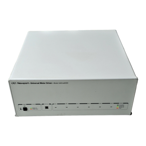
Page 28: Figure 2.3-2 - Unidrive6000 Front And Rear View
Universal Motor Driver UniDrive6000 POWER STATUS STOP ALL AXIS 1 AXIS 2 AXIS 3 AXIS 4 AXIS 5 AXIS 6 STATUS NO DRIVER MOTOR ON POWER ON MOTOR OFF POWER FAULT FAULT FRONT AXIS POWER CONTROLLER SUPPLY CONTROLLER INPUT LINE CAUTION: VOLTAGE SELECT... -
Page 29: Installation And Connection
Installation and Connection 2.4.1 Installing the ESP6000 Controller Card and Software Driver Power down the computer. Refer to the computer user manual for procedures. WARNING This product operates with voltages that can be lethal. Pushing objects of any kind into cabinet slots or holes, or spilling any liquid on the product, may touch hazardous voltage points or short out parts. -
Page 30: Figure 2.4-1 - Enclosure Removal
PCI card slot, and remove the panel. Due to varying card guide configurations of computers, it may be neces- sary to remove the bracket at the end of the ESP6000 card in order to install the card. Make a visual determination before attempting to con- tinue installation. -
Page 31: Figure 2.4-2 - Esp6000 Controller Card Insertion Orientation
Push down gently until the edge connector on the bottom of the ESP6000 card mates with the connector at the bottom of the computer chassis. Install the retaining screw into the bracket at the top of the ESP6000 card. Re-attach the enclosure and plug in the computer AC power cord. -
Page 32: Figure 2.4-4 - Install From Disk Message (Representative Screen Only)
Copy Manufacturer’s Files From: [A:\ Figure 2.4-4 — Install From Disk Message (Representative Screen Only) Insert the disk labeled ESP6000 Windows 95 Device Driver into the com- puter floppy disk drive and select OK. Another Windows 95 prompt appears (see Figure 2.4-5). -
Page 33: Installing Windows Software
The Windows Interface Software disk set (which includes software utili- ties, DLL, and language libraries) can be installed any time after the ESP6000 controller card and driver software have been installed. From the Windows 95 desk-top, press the start button and select SETTINGS and then CONTROL PANEL. -
Page 34: Figure 2.4-8 - Add/Remove Programs Properties Menu
Select ADD/REMOVE PROGRAMS from the Control Panel menu. The Add/ Remove Programs Properties menu appears (see Figure 2.4-8). Figure 2.4-8 — Add/Remove Programs Properties Menu Select the Install/Uninstall tab from the Add/Remove Programs Properties menu, then select INSTALL. The Install Program From Floppy Disk Or CD- ROM screen appears (see Figure 2.4-9). -
Page 35: Figure 2.4-9 - Install Program From Floppy Disk Or Cd-Rom Screen
Figure 2.4-9 — Install Program From Floppy Disk Or CD-ROM Screen Insert the disk labeled ESP6000 Windows Interface Software Disk 1 of 4 into the floppy drive and select NEXT. The Run Installation Program screen appears (Figure 2.4-10). Verify that the path appears as shown in the screen and select FINISH. -
Page 36: Figure 2.4-11 - Esp Welcome Screen
Figure 2.4-11 — ESP Welcome Screen Select NEXT. The ESP Select Destination Directory screen appears (see Figure 2.4-12). Figure 2.4-12 — ESP Select Destination Directory Screen 2 - 1 2 Artisan Technology Group - Quality Instrumentation ... Guaranteed | (888) 88-SOURCE | www.artisantg.com... -
Page 37: Figure 2.4-13 - Esp Ready To Install Screen
Select NEXT. The ESP Ready To Install screen appears (see Figure 2.4-13). Figure 2.4-13 — ESP Ready To Install Screen Section 2 — System Set-Up 2 - 1 3 Artisan Technology Group - Quality Instrumentation ... Guaranteed | (888) 88-SOURCE | www.artisantg.com... -
Page 38: Figure 2.4-14 - Installing Message Screen
Select NEXT. The Installing message screen appears (see Figure 2.4-14). Figure 2.4-14 — Installing Message Screen When installation of the first disk is complete, the Insert New Disk message screen appears (see Figure 2.4-15) prompting the user to insert disk 2. Follow the prompts for disks 2, 3, and 4. -
Page 39: Verifying Communication Between The Esp6000 Card And The Pc
Select FINISH to return to the Control panel menu. Figure 2.4-16 — ESP Installation Completed Screen 2.4.3 Verifying Communication Between the ESP6000 Card and the PC The ESP 6000 software performs a verification each time the system is booted-up. An ESP Initialization message screen appears that indicates the ESP6000 controller card status, the UniDrive axes configured, and ESP-compatible stages found during initialization (see Figure 2.4-17). -
Page 40: Selecting The Unidrive6000 Line Voltage
If the ESP6000 controller card is not present or communicating then an error message appears (see Figure 2.4-18). Figure 2.4-18 — ESP6000 Error Message Screen 2.4.4 Selecting The UniDrive6000 Line Voltage Unplug the UniDrive6000 AC power cord from the power source, and disconnect it from any equipment. -
Page 41: Figure 2.4-19 - Line Voltage Select Switch
AXIS POWER CONTROLLER SUPPLY LINE VOLTAGE CAUTION: SELECT NO USER SERVICEABLE 90-120V OR PARTS INSIDE. REFER 200-240V SERVICING TO QUALIFIED 230V 115V 50/60 Hz SERVICE PERSONNEL. MAX 4 AMP WARNING: FOR CONTINUED PROTECTION AGAINST FIRE RISK, REPLACE ONLY WITH FUSE 115V OF SPECIFIED RATING. -
Page 42: Connecting Stages
(encoder, limits, and home signals). The cable is termi- nated with a standard 25-pin D-Sub connector. CAUTION Make sure the UniDrive6000 and ESP6000 are powered off. CAUTION Position stage(s) on a flat, stable surface before connection to a rack-mounted UniDrive Carefully connect one end of the cable to the stage and the other end to a driver axis on the UniDrive6000 (see Figure 2.4-20). -
Page 43: Connecting The Unidrive6000 To The Esp6000 Controller Card
With the UniDrive6000 and personal computer powered off, attach the supplied 100-pin cable to the connector labeled CONTROLLER INPUT at the rear of the UniDrive6000. Next attach the cable to the ESP6000 card connector at the rear of the personal computer (see Figure 2.4-21). Con- nector orientation is shown in Appendix C. - Page 44 2 - 2 0 Artisan Technology Group - Quality Instrumentation ... Guaranteed | (888) 88-SOURCE | www.artisantg.com...
-
Page 45: Section 3 - Quick Start
General Description The following paragraphs cover procedures for operation after all equip- ment has been connected, and both the ESP6000 controller card driver and setup utility have been installed (see the System Setup section). Informa- tion includes how to power up the UniDrive and stage motor(s), activate home and jog motions, and to shut down the system. -
Page 46: Figure 3.2-1 - Motion Drop-Down Menu
Figure 3.2-1 — Motion Drop-Down Menu Select ENABLE. The Motor Power menu appears (see Figure 3.2-2). Figure 3.2-2 — Motor Power Menu Select numbered axes buttons one-by-one to turn on the motors you have connected to the specific axes, or select ALL ON to enable all motors. Buttons for enabled and connected motors will illuminate green, and the axis LED on the UniDrive will turn green to indicate a motor-on condition. -
Page 47: Homing A Stage
Homing a Stage From the Motion drop-down menu, select HOME. The Home Stages screen appears (see Figure 3.3-1) Figure 3.3-1 — Home Stages Menu Select an axis and search mode (Home Switch Only or Home Switch & Index), enter the number of units in the Home Speed input box, and Select START to home the stage(s). -
Page 48: Jog
From the Motion drop-down menu, select JOG (See Figure 3.2-1) or select the JOG button from the tool bar. The Jog menu appears (see Figure 3.4-1). Figure 3.4-1 — Jog Menu NOTE Enable stage(s) motor power before jogging. 3 - 4 Artisan Technology Group - Quality Instrumentation ... -
Page 49: Figure 3.4-2 - Speed Menu
Next select SPEED from the Jog menu (see Figure 3.4-2), then select the X or Y axis option from the Speed drop-down menu. The Set X/Y Speed menu appears (see Figure 3.4-3). Figure 3.4-2 — Speed Menu Figure 3.4-3 — Set X(Y) Speed Menu Enter a value in the New Speed text box and select OK. -
Page 50: System Shut-Down
NOTE You cannot designate both the X and Y axes for the same stage axis number. Press an X or Y arrow key to move a stage. Press and quickly release the arrow key for one-count (single) motions. Press and hold down an arrow key for continuous movement, and release the arrow key to stop movement. -
Page 51: Section 4 - Windows Utilities
4.1.3 Operation At start up the program will load the Dynamic Link Library (DLL) and initialize the ESP6000 controller card. When the system is ready to oper- ate a message window will identify ESP-compatible stages and motor drivers, and indicate that initialization status. -
Page 52: Figure 4.1-1 - Main Menu
Table 4.1-1 — Stage (Motor) Type Settings Motor Micro-Step Full-Step Motor Type Current Factor Resolution —- —- Stepper —- Table 4.1-2 — Stage (Motor) Trajectory Settings Characteristic Nominal Maximum Resolution/Units —- Speed Acceleration Deceleration Jerk NOTE Save configuration input on a systematic basis to ensure operating parameters are not lost. -
Page 53: Figure 4.1-2 - File Menu
Figure 4.1-2 — File Menu 4.1.3.1.1 Reset System Select RESET SYSTEM to perform a hardware reset of the ESP6000 control- ler card and UniDrive (if attached). The user will be prompted to verify the selection. After a hardware reset the ESP6000 will search for ESP- compatible stages and configure the UniDrive accordingly. -
Page 54: Figure 4.1-3 - Setup Menu
4.1.3.1.5 Exit Select EXIT to leave the ESP6000 utility and return to the Windows desktop. 4.1.3.2 Setup Menu The Setup Menu consists of a series of drop-down menus, as shown in Figure 4.1-3. Menu functions are described in the following paragraphs. -
Page 55: Figure 4.1-4 - Setup Resolution Sub-Menu
4.1.3.2.1 Motion The Motion drop-down menu includes a Setup Resolution sub-menu and a Motion Setup sub-menu. The Setup Resolution sub-menu enables a user to set resolution and user units by specifying unit of measure and input value. The Motion Setup sub-menu defines trajectory and PID parameters. Select MOTION and then RESOLUTION to access the Setup Resolution sub-menu (see Figure 4.1-4). -
Page 56: Figure 4.1-5 - Motion Setup Pid Tab
Figure 4.1-5 — Motion Setup PID Tab Figure 4.1-6 — Motion Setup Trajectory Tab Refer to Servo Tuning, Section 7, for tuning guidelines before entering values. Select the appropriate axis and enter parameters to set trajectory and PID. 4 - 6 Artisan Technology Group - Quality Instrumentation ... -
Page 57: Figure 4.1-7 - Setup Faults Sub-Menu
Default settings for ESP-compatible devices can be modified from the PID and trajectory tabs. Select Save from the Tool Bar to save the parameters to ESP6000 controller non-volatile flash EPROM memory. 4.1.3.2.2 Faults The Faults menu includes a Setup Faults sub-menu which enables a user to indicate a selection of events to be triggered if specified faults occur. -
Page 58: Figure 4.1-8 - Setup Hardware Amplifier I/O Tab
4.1.3.2.3 Hardware The Hardware menu includes a Setup Hardware sub-menu to configure hardware. Select HARDWARE to access the Setup Hardware sub-menu. The Setup Hardware sub-menu includes tabs for defining amplifier I/O, analog I/O, digital I/O, servo DAC offset, and travel limit parameters. The tabs are shown in Figures 4.1-8 through 4.1-12 and described in the following paragraphs. -
Page 59: Figure 4.1-9 - Setup Hardware Analog I/O Tab
Use the Amplifier I/O tab to configure a non-ESP compatible motor ampli- fier. Select the axis and motor type, then designate settings. Set Amplifier Fault in the applicable Setup Faults sub-menu tab before selecting the Amplifier Fault Input option. Figure 4.1-9 — Setup Hardware Analog I/O Tab Use the Analog I/O tab to select gain and range settings for the analog-to- digital conversion. -
Page 60: Figure 4.1-11 - Setup Hardware Servo Dac Offset Tab
Use the Digital I/O tab to define port direction. Select bits in the Bit Settings sub-panel to designate the bits for output (red illumination indicates a HIGH logic level). Figure 4.1-11 — Setup Hardware Servo DAC Offset Tab Use the Servo DAC Offset tab to designate voltage (±1 volt maximum) offset on the servo digital-to-analog outputs for each axis. -
Page 61: Figure 4.1-13 - Setup Unidrive Sub-Menu
4.1.3.2.4 Firmware The Hardware menu includes a Setup Firmware sub-menu for downloading firmware to the ESP6000 controller card in the event that it becomes necessary (e.g., future upgrades). Select FIRMWARE to begin the process of erasing existing firmware and downloading new firmware on the ESP6000 controller card. -
Page 62: Figure 4.1-14 - Motion Menu
4.1.3.3 Motion Menu The Motion Menu consists of a series of drop-down menus, as shown in Figure 4.1-14. Menu functions are described in the following paragraphs. Figure 4.1-14 — Motion Menu 4.1.3.3.1 Stop Select STOP to make the Stop Motion message screen appear (see Figure 4.1-15). -
Page 63: Figure 4.1-16 - Cycle Motors Sub-Menu
Figure 4.1-16 — Cycle Motors Sub-Menu Select the appropriate axis, the absolute position displacements in user units, and enter a dwell time (desired waiting period between positions) for each movement. There is no constraint for dwell. Select the stop-light icon to stop and start the motion. 4.1.3.3.5 Enable Select ENABLE to power on stage motors. -
Page 64: Figure 4.1-18 - Position Status Menu
4.1.3.4.1 Position Select POSITION to determine axis-by-axis position expressed in terms of user units. The Position Status sub-menu appears (see Figure 4.1-18). Figure 4.1-18 — Position Status Menu Select a single axis or multiple axis to display information. Axes 7 and 8 should be considered “virtual axes”... -
Page 65: Servo Tuning Utility
At boot-up, the program will load the Dynamic Link Library (DLL) and will attempt to establish communication with the ESP6000 controller card. If communication does not occur, the program will assume the ESP6000 card was not initialized, and will initiate a reset sequence and initialize the ESP6000 card (but not the personal computer) and the UniDrive6000. -
Page 66: Figure 4.2-1 - Servo Tuning Main Screen
Figure 4.2-1 — Servo Tuning Main Screen Default settings are provided for ESP-compatible stages, but settings for non-ESP-compatible stages must be individually configured by the user. To get detailed information about the functionality and usage of the tuning software utility, click the right mouse button on the desired object and select DESCRIPTION. -
Page 67: Section 5 - Programming
The ESP6000 controller card and device driver must be installed correctly before programming can begin. The Dynamic Link Library (DLL) provides communication to the ESP6000 controller card via the PCI bus. When the system is initialized the DLL will make a call to the device driver to open communications. -
Page 68: Commands
Table 5.2-2 — API Function Categories Category Initialization Configuration Motion Trajectory Motion-Related Servo Data Acquisition Digital I/O System Commands 5.3.1 Command Summary Commands are categorized by function in Table 5.3-1. Table 5.3-1 — Commands Function Command Page Initialization esp_init_system(void) ............... 5-8 esp_open_system(void) .............. - Page 69 Function Command Page Configuration (Cont.) esp_get_ampio_config(long axis, long *config) ......5-20 esp_set_feedback_config(long axis, long config) ......5-22 esp_get_feedback_config(long axis, long *config) ....... 5-22 esp_set_e_stop_config(long axis, long config) ......5-24 esp_get_e_stop_config(long axis, long *config) ......5-24 esp_set_dac_offset(long axis, float offset) ........5-25 esp_get_dac_offset(long axis, float *offset) ........
- Page 70 Function Command Page Trajectory (Cont.) esp_get_max_accel(long axis, float *accel) ........5-50 esp_set_jerk(long axis, float jerk) ............ 5-51 esp_get_jerk(long axis, float *jerk) ..........5-51 esp_set_max_jerk(long axis, float jerk) .......... 5-52 esp_get_max_jerk(long axis, float *jerk) ........5-52 esp_set_home_speed(long axis, float speed) ........ 5-53 esp_get_home_speed(long axis, float *speed) ......
- Page 71 Function Command Page Motion-Related (Cont.) esp_get_motor_current(long axis, float *current) ....... 5-72 esp_set_tach_constant(long axis, float tach) ....... 5-73 esp_get_tach_constant(long axis, float *tach) ......5-73 esp_set_gear_constant(long axis, float gear) ....... 5-74 esp_get_gear_constant(long axis, float *gear) ......5-74 Servo esp_set_kp(long axis, float kp) ............5-78 esp_get_kp(long axis, float *kp) .............
- Page 72 Function Command Page Digital I/O (Cont.) esp_get_portabc_dir(long *PortA, long *PortB, long *PortC) ............... 5-100 esp_set_dio_porta(long data) ............5-101 esp_get_dio_porta(long *data) ............. 5-101 esp_set_dio_portb(long data) ............5-102 esp_get_dio_portb(long *data) ............. 5-102 esp_set_dio_portc(long data) ............5-103 esp_get_dio_portc(long *data) ............. 5-103 System esp_get_error_num(int *error, int *ServoTick) ......5-106 esp_get_error_string(char *ErrorString, int *error, int *ServoTick) ..................
-
Page 73: Initialization
Initialization Section 5 — Programming Artisan Technology Group - Quality Instrumentation ... Guaranteed | (888) 88-SOURCE | www.artisantg.com... - Page 74 20 seconds to completely upload and parse all ESP-compat- ible stage data and configure UniDrive axes. The esp_init_system() API function must be the first ESP function called in any application. All motors are turned OFF and ESP6000 hardware is reset after an esp_init_system() function call. Returns: ESPOK, ESPERROR...
-
Page 75: Esp_Open_System(Void)
#include “esp6000.h” Synopsis: int esp_open_system(void) Arguments: None Library Location: \esp6000.dll Description: esp_open_system() initializes the ESP6000 PCI bus communication, but does not invoke a board hardware reset. Returns: ESPOK, ESPERROR Hint: Always evaluate returned value from esp_open_system() Usage Example: # include <stdio.h>... -
Page 76: Esp_Update_Unidrive(Long Axis)
ESPOK, ESPERROR Hint: Usage Example: #include “esp6000.h” main() long error, servotick; if (!esp_init_system()) printf(“ESP6000 Not Initialized! \r\n”); exit(-1); /* Change Axis-1 Motor Current */ esp_motor_current(1, 1.9); /* Update Unidrive6000 Axis-1 */ esp_update_unidrive(1); /* Save new settings to non-volatile memory */ esp_save_parameters();... -
Page 77: Configuration
Configuration Section 5 — Programming 5-11 Artisan Technology Group - Quality Instrumentation ... Guaranteed | (888) 88-SOURCE | www.artisantg.com... -
Page 78: Esp_Set_Motor_Type(Long Axis, Long Mtype)
This is necessary because the ESP6000 needs to apply different control algorithms for different motor types. For example, DC servos are controlled via digital-to-analog converter (DAC) whereas stepper motors are positioned via digital rate multiplier. -
Page 79: Esp_Get_Sys_Config(Long *Config)
Library Location: \esp6000.dll Description: esp_get_sys_config() reports the present ESP system stage/driver configuration. After each system reset or initialization the ESP6000 detects the presence of UniDrive6000 driver channels and ESP-compatible stages connected. BIT# VALUE DEFINITION axis-1 UniDrive6000 not detected... - Page 80 Report ESP System Configuration (Continued) Usage Example: #include “esp6000.h” main() long error, servotick, systconfig; if (!esp_init_system()) printf(“ESP6000 Not Initialized! \r\n”); exit(-1); /* Get ESP System Configuration */ esp_get_sys_config(&sysconfig); /* print present system configuration */ printf(“Configuration = %x \r\n”, sysconfig);...
-
Page 81: Esp_Set_Sys_Fault_Config(Long Config)
Set System Configuration Register esp_get_sys_fault_config Report System Configuration Register Synopsis: #include “esp6000.h” int esp_set_sys_fault_config(long config) int esp_get_sys_fault_config(long *config) Arguments: long config configuration register Library Location: \esp6000.dll Description: esp_set_sys_fault_config() is used to configure system fault checking, event handling, and general setup for all axes. - Page 82 ESPOK, ESPERROR Hint: Usage Example: #include “esp6000.h” main() if (!esp_init_system()) printf(“ESP6000 Not Initialized! \r\n”); exit(-1); /* Disable Motor Power & Flag Interlock Error */ status = esp_set_sys_fault_config(0x0b); See Also: 5-16 Artisan Technology Group - Quality Instrumentation ... Guaranteed | (888) 88-SOURCE | www.artisantg.com...
-
Page 83: Esp_Set_Followerr_Config(Long Axis, Long Config)
Returns: ESPOK, ESPERROR Hint: Usage Example: #include “esp6000.h” main() if (!esp_init_system()) printf(“ESP6000 Not Initialized! \r\n”); exit(-1); /* Disable Motor Power On Following Error */ esp_set_followerr_config(1,0x03); See Also: esp_set_following_error() Section 5 — Programming 5-17 Artisan Technology Group - Quality Instrumentation ... Guaranteed | (888) 88-SOURCE | www.artisantg.com... -
Page 84: Esp_Set_Hardlimit_Config(Long Axis, Long Config)
• • • reserved reserved Returns: ESPOK, ESPERROR Hint: Newport stages use “active high” travel limit input setting. Usage Example: #include “esp6000.h” main() if (!esp_init_system()) printf(“ESP6000 Not Initialized! \r\n”); exit(-1); /* Abort Motion & Flag Error On Hardware Limit */ esp_set_hardlimit_config(1,0x0d);... -
Page 85: Esp_Set_Softlimit_Config(Long Axis, Long Config)
Returns: ESPOK, ESPERROR Hint: Usage Example: #include “esp6000.h” main() if (!esp_init_system()) printf(“ESP6000 Not Initialized! \r\n”); exit(-1); /* Abort Motion & Flag Error On Software Limit */ esp_set_softlimit_config(1,0x0d); See Also: Section 5 — Programming 5-19 Artisan Technology Group - Quality Instrumentation ... Guaranteed | (888) 88-SOURCE | www.artisantg.com... -
Page 86: Esp_Set_Ampio_Config(Long Axis, Long Config)
Set Amplifier I/O Configuration Register esp_get_ampio_config Report Amplifier I/O Configuration Register Synopsis: #include “esp6000.h” int esp_set_ampio_config(long axis, long config) int esp_get_ampio_config(long axis, long *config) Arguments: long axis axis number from 1 to 6 long config configuration register Library Location: \esp6000.dll... - Page 87 Returns: ESPOK, ESPERROR Hint: Usage Example: #include “esp6000.h” main() if (!esp_init_system()) printf(“ESP6000 Not Initialized! \r\n”); exit(-1); /* Disable Motor & Flag Error On Amp Fault */ esp_set_ampio_config(1,0x0b); See Also: Section 5 — Programming 5-21 Artisan Technology Group - Quality Instrumentation ... Guaranteed | (888) 88-SOURCE | www.artisantg.com...
-
Page 88: Esp_Set_Feedback_Config(Long Axis, Long Config)
Set Amplifier Input Configuration Register esp_get_feedback_config Report Amplifier Input Configuration Register Synopsis: #include “esp6000.h” int esp_set_feedback_config(long axis, long config) int esp_get_feedback_config(long axis, long *config) Arguments: long axis axis number from 1 to 6 long config configuration register Library Location: \esp6000.dll... - Page 89 Returns: ESPOK, ESPERROR Hint: Usage Example: #include “esp6000.h” main() if (!esp_init_system()) printf(“ESP6000 Not Initialized! \r\n”); exit(-1); /* Set Flag On Feedback Error */ esp_set_feedback_config(1,0x09); See Also: Section 5 — Programming 5-23 Artisan Technology Group - Quality Instrumentation ... Guaranteed | (888) 88-SOURCE | www.artisantg.com...
-
Page 90: Esp_Set_E_Stop_Config(Long Axis, Long Config)
Returns: ESPOK, ESPERROR Hint: Usage Example: #include “esp6000.h” main() if (!esp_init_system()) printf(“ESP6000 Not Initialized! \r\n”); exit(-1); /* Abort Motion On E-STOP Event */ esp_set_e_stop_config(1,0x05); See Also: 5-24 Artisan Technology Group - Quality Instrumentation ... Guaranteed | (888) 88-SOURCE | www.artisantg.com... -
Page 91: Esp_Set_Dac_Offset(Long Axis, Float Offset)
Returns: ESPOK, ESPERROR Hint: Usage Example: #include “esp6000.h” main() if (!esp_init_system()) printf(“ESP6000 Not Initialized! \r\n”); exit(-1); /* Set Axis 1 DAC Offset */ esp_set_dac_offset(1, -0.075); /* Save Offset To Non-volatile Memory */ esp_save_parameters(); See Also: esp_save_parameters() Section 5 — Programming 5-25 Artisan Technology Group - Quality Instrumentation ... - Page 92 Library Location: \esp6000.dll Description: esp_save_parameters() API function call causes the ESP6000 to save present param- eters to non-volatile flash EPROM memory. Parameters saved to flash EPROM are automatically restored to working registers after system initialization or reset. NOTE Saved axis settings are automatically overwritten when a different ESP-compatible stage is detected in the same axis channel.
-
Page 93: Esp_Get_Hardware_Status(Long *Hardstat1, Long *Hardstat2)
Report Hardware Status For All Axes #include “esp6000.h” Synopsis: int esp_get_hardware_status(long *hardstat1, long *hardstat2) Arguments: long hardstat1 general hardware status register 1 long hardstat2 general hardware status register 2 Library Location: \esp6000.dll Description: (Register #1) esp_get_hardware_status() is used to get general hardware status for all axes. This routine allows you to observe the various digital input signals as they appear to the controller. - Page 94 esp_get_hardware_status Report Hardware Status For All Axes (Continued) axis 4 amplifier fault input low axis 4 amplifier fault input high axis 5 amplifier fault input low axis 5 amplifier fault input high axis 6 amplifier fault input low axis 6 amplifier fault input high reserved reserved reserved...
- Page 95 • • reserved reserved Returns: ESPOK, ESPERROR Hint: Usage Example: #include “esp6000.h” main() { long stat1, stat2; if (!esp_init_system()) exit(-1); /* Get Board Hardware Status */ esp_get_hardware_status(&stat1, &stat2); printf(“Hardware Status = %x,%x /n/r”, stat1, stat2) See Also: Section 5 — Programming 5-29 Artisan Technology Group - Quality Instrumentation ...
- Page 96 5-30 Artisan Technology Group - Quality Instrumentation ... Guaranteed | (888) 88-SOURCE | www.artisantg.com...
-
Page 97: Motion
Motion Section 5 — Programming 5-31 Artisan Technology Group - Quality Instrumentation ... Guaranteed | (888) 88-SOURCE | www.artisantg.com... -
Page 98: Esp_Move_Absolute(Long Axis, Double Position)
Remember to specify position parameter in user units (e.g., millimeters) Usage Example: #include “esp6000.h” main() long error, servotick; double position; if (!esp_init_system()) printf(“ESP6000 Not Initialized! \r\n”); exit(-1); /* enable motor power */ esp_enable_motor(2); /* move axis 2 to absolute position -3.0 */ esp_move_absolute(2,-3.0);... - Page 99 Hint: Usage Example: #include “esp6000.h” main() long error, servotick; double position; if (!esp_init_system()) printf(“ESP6000 Not Initialized! \r\n”); exit(-1); /* enable motor power */ esp_enable_motor(2); /* move axis 2 to absolute position -3.0 */ esp_move_absolute(2,-3.0); while (!esp_move_done(2)); /* Wait 2.5 seconds */ esp_delay(2.5);...
-
Page 100: Esp_Delay_After_Stop(Long Axis, Float Time)
Hint: Usage Example: #include “esp6000.h” main() long error, servotick; double position; if (!esp_init_system()) printf(“ESP6000 Not Initialized! \r\n”); exit(-1); /* enable motor power */ esp_enable_motor(2); /* move axis 2 to absolute position -3.0 */ esp_move_absolute(2,-3.0); /* Wait 2.5 seconds */ esp_delay_after_stop(2,2.5);... -
Page 101: Esp_Move_Relative(Long Axis, Double Position)
Returns: ESPOK, ESPERROR Hint: Usage Example: #include “esp6000.h” main() long error, servotick; if (!esp_init_system()) printf(“ESP6000 Not Initialized! \r\n”); exit(-1); /* enable motor power */ esp_enable_motor(2); /* move axis-2 relative -3 units */ esp_move_relative(2,-3); /* check error status */ esp_get_error_num(&error,&ServoTick) ;... -
Page 102: Esp_Find_Home(Long Axis, Long Mode)
ESPOK, ESPERROR Hint: Usage Example: #include “esp6000.h” main() long error, servotick; if (!esp_init_system()) printf(“ESP6000 Not Initialized! \r\n”); exit(-1); /* Enable Axis 2 Motor Power */ esp_enable_motor(2); /* Set Axis Home Speed */ esp_set_home_speed(2,20.0); /* Begin Home Search On Axis 2 */ esp_find_home(2,1);... - Page 103 Hint: Usage Example: #include “esp6000.h” main() long error, servotick; double position; if (!esp_init_system()) printf(“ESP6000 Not Initialized! \r\n”); exit(-1); /* enable motor power */ esp_enable_motor(2); /* move axis 2 to absolute position -3.0 */ esp_move_absolute(2,-3.0); while (!esp_move_done(2)); /* check error status */ esp_get_error_num(&error,&ServoTick) ;...
- Page 104 Query for possible motion/system errors after homing. Usage Example: #include “esp6000.h” main() long error, servotick; if (!esp_init_system()) printf(“ESP6000 Not Initialized! \r\n”); exit(-1); /* Enable Axis 2 Motor Power */ esp_enable_motor(2); /* Set Axis Home Speed */ esp_set_home_speed(2,20.0); /* Begin Home Search On Axis 2 */ esp_find_home(2,1);...
- Page 105 Report Motion Status For All Axes #include “esp6000.h” Synopsis: int esp_get_motion_status(long *mstat) Arguments: long mstat motion status register Library Location: \esp6000.dll Description: esp_get_motion_status() is used to report motion status for all axes. esp_get_motion_status() API call reports all axes’ motion status in binary format where axis-1 corresponds to bit-0 and axis-6 bit-5.
-
Page 106: Esp_Get_Motion_Status(Long *Mstat)
Report Motion Status For All Axes (Continued) Usage Example: #include “esp6000.h” main() long error, servotick, mstat; double position; if (!esp_init_system()) printf(“ESP6000 Not Initialized! \r\n”); exit(-1); /* enable motor power */ esp_enable_motor(1); esp_enable_motor(2); /* move axis 2 to absolute position -3.0 */ esp_move_absolute(1,+5.0);... -
Page 107: Esp_Stop(Long Axis)
Stop Specified Axes #include “esp6000.h” Synopsis: int esp_stop(long axis) Arguments: long axis axis number from 1-6, axis = 0 stops all axes Library Location: \esp6000.dll Description: esp_stop() causes all axes in motion to immediately decelerate using deceleration rate previously set by esp_set_decel() function call. -
Page 108: Esp_Stop_All(Void)
Stop All Axes #include “esp6000.h” Synopsis: int esp_stop_all(void) Arguments: none Library Location: \esp6000.dll Description: esp_ stop() causes all axes in motion to immediately decelerate using deceleration rate previously set by esp_set_decel() function call. Returns: ESPOK, ESPERROR Hint: Usage Example: #include “esp6000.h”... - Page 109 Trajectory Section 5 — Programming 5-43 Artisan Technology Group - Quality Instrumentation ... Guaranteed | (888) 88-SOURCE | www.artisantg.com...
- Page 110 Set Axis Trajectory Mode esp_get_traj_mode Report Axis Trajectory Mode Setting Synopsis: #include “esp6000.h” int esp_set_traj_mode(long axis, long mode) int esp_get_traj_mode(long axis, long *mode) Arguments: long axis axis number from 1-6 long mode possible trajectory modes are: TRAPEZOID, TRAPSTEP, SCURVE, SLAVEP,...
- Page 111 Report Axis Trajectory Mode Setting (Continued) Usage Example: #include “esp6000.h” main() long error, servotick; if (!esp_init_system()) printf(“ESP6000 Not Initialized! \r\n”); exit(-1); /* set S-Curve trajectory mode */ esp_set_traj_mode(1, SCURVE); /* set axis 1 trajectory parameters */ esp_set_speed(1, 30.0); esp_set_accel(1, 200.0);...
- Page 112 Returns: ESPOK, ESPERROR Hint: Usage Example: #include “esp6000.h” main() long error, servotick; if (!esp_init_system()) printf(“ESP6000 Not Initialized! \r\n”); exit(-1); /* set axis 1 trajectory parameters */ esp_set_speed(1, 30.0); esp_set_accel(1, 200.0); esp_set_decel(1, 150.0); /* check error status */ esp_get_error_num(&error,&ServoTick) ; if (error) printf(“Error %d Reported!\r\n”, error);...
- Page 113 Returns: ESPOK, ESPERROR Hint: Usage Example: #include “esp6000.h” main() long error, servotick; if (!esp_init_system()) printf(“ESP6000 Not Initialized! \r\n”); exit(-1); /* set axis 1 trajectory parameters */ esp_set_max_speed(1, 100.0); esp_set_max_accel(1, 500.0); esp_set_max_jerk(1,100.0); /* check error status */ esp_get_error_num(&error,&ServoTick) ; if (error) printf(“Error %d Reported!\r\n”, error);...
- Page 114 Hint: Acceleration typically equal to deceleration. Usage Example: #include “esp6000.h” main() long error, servotick; if (!esp_init_system()) printf(“ESP6000 Not Initialized! \r\n”); exit(-1); /* set axis 1 trajectory parameters */ esp_set_speed(1, 30.0); esp_set_accel(1, 200.0); esp_set_decel(1, 150.0); /* check error status */ esp_get_error_num(&error,&ServoTick) ;...
- Page 115 Deceleration typically is set equal to acceleration. Usage Example: #include “esp6000.h” main() long error, servotick; if (!esp_init_system()) printf(“ESP6000 Not Initialized! \r\n”); exit(-1); /* set axis 1 trajectory parameters */ esp_set_speed(1, 30.0); esp_set_accel(1, 200.0); esp_set_decel(1, 150.0); /* check error status */ esp_get_error_num(&error,&ServoTick) ;...
- Page 116 Returns: ESPOK, ESPERROR Hint: Usage Example: #include “esp6000.h” main() long error, servotick; if (!esp_init_system()) printf(“ESP6000 Not Initialized! \r\n”); exit(-1); /* set axis 1 trajectory parameters */ esp_set_max_speed(1, 100.0); esp_set_max_accel(1, 500.0); esp_set_max_jerk(1,100.0); /* check error status */ esp_get_error_num(&error,&ServoTick) ; if (error) printf(“Error %d Reported!\r\n”, error);...
- Page 117 Returns: ESPOK, ESPERROR Hint: Usage Example: #include “esp6000.h” main() long error, servotick; if (!esp_init_system()) printf(“ESP6000 Not Initialized! \r\n”); exit(-1); /* set S-Curve trajectory mode */ esp_set_traj_mode(1, SCURVE); /* set axis 1 trajectory parameters */ esp_set_speed(1, 30.0); esp_set_accel(1, 200.0); esp_set_decel(1, 150.0);...
- Page 118 Returns: ESPOK, ESPERROR Hint: Usage Example: #include “esp6000.h” main() long error, servotick; if (!esp_init_system()) printf(“ESP6000 Not Initialized! \r\n”); exit(-1); /* set axis 1 trajectory parameters */ esp_set_max_speed(1, 100.0); esp_set_max_accel(1, 500.0); esp_set_max_jerk(1,100.0); /* check error status */ esp_get_error_num(&error,&ServoTick) ; if (error) printf(“Error %d Reported!\r\n”, error);...
-
Page 119: Esp_Set_Home_Speed(Long Axis, Float Speed)
During first time system testing set home speed to 1/10 of maximum speed. Usage Example: #include “esp6000.h” main() long error, servotick; if (!esp_init_system()) printf(“ESP6000 Not Initialized! \r\n”); exit(-1); /* Enable Axis 2 Motor Power */ esp_enable_motor(2); /* Set Axis Home Speed */ esp_set_home_speed(2,20.0);... -
Page 120: Esp_Set_Startstop_Speed(Long Axis, Float Speed)
Most applications never need to change ESP-compatible default values. Usage Example: #include “esp6000.h” main() long error, servotick; if (!esp_init_system()) printf(“ESP6000 Not Initialized! \r\n”); exit(-1); /* set axis 1 speed parameters */ esp_set_speed(1, 30.0); esp_set_startstop_speed(1, 0.02); /* check error status */ esp_get_error_num(&error,&ServoTick) ;... -
Page 121: Esp_Set_Jog_Speed(Long Axis, Float Speed)
Set Axis Jog Mode Speed esp_get_jog_speed Report Axis Jog Mode Speed Setting Synopsis: #include “esp6000.h” int esp_set_jog_speed(long axis, float speed) int esp_get_jog_speed(long axis, float *speed) Arguments: long axis axis number from 1-6 float speed target jog speed and direction <= maximum speed (in user units/second) Library Location: \esp6000.dll... - Page 122 5-56 Artisan Technology Group - Quality Instrumentation ... Guaranteed | (888) 88-SOURCE | www.artisantg.com...
-
Page 123: Motion-Related
Motion-Related Section 5 — Programming 5-57 Artisan Technology Group - Quality Instrumentation ... Guaranteed | (888) 88-SOURCE | www.artisantg.com... -
Page 124: Esp_Enable_Motor(Long Axis)
Hint: Usage Example: #include “esp6000.h” main() long error, servotick; double position; if (!esp_init_system()) printf(“ESP6000 Not Initialized! \r\n”); exit(-1); /* enable motor power */ esp_enable_motor(2); /* move axis 2 to absolute position -3.0 */ esp_move_absolute(2,-3.0); while (!esp_move_done(2)); /* check error status */ esp_get_error_num(&error,&ServoTick) ;... - Page 125 Hint: Usage Example: #include “esp6000.h” main() long error, servotick; double position; if (!esp_init_system()) printf(“ESP6000 Not Initialized! \r\n”); exit(-1); /* enable motor power */ esp_enable_motor(2); /* move axis 2 to absolute position -3.0 */ esp_move_absolute(2,-3.0); while (!esp_move_done(2)); /* check error status */ esp_get_error_num(&error,&ServoTick) ;...
-
Page 126: Esp_Get_Motor_Onoff_Status(Long *Onoff)
Report Motor ON/OFF status #include “esp6000.h” Synopsis: int esp_get_motor_onoff_status(long *onoff) Arguments: long *onoff motor ON/OFF status where bits 0 - 5 correspond to axes 1-6 Library Location: \esp6000.dll Description: esp_get_motor_onoff_status() reports all axes motor on/off status in binary format where axis-1 corresponds to bit-0 and axis-6 bit-5. - Page 127 Report Motor ON/OFF status (Continued) Usage Example: #include “esp6000.h” main() long error, servotick, onoff; if(!esp_init_system()) printf(“ESP6000 Not Initialized! \r\n”); exit(-1); /* enable motor power */ esp_enable_motor(2); esp_get_motor_onoff_status(&onoff); /* test for exis 2 enabled */ if(onoff& 0x02) printf(“Axis 2 Motor Enabled! \r\n”);...
-
Page 128: Esp_Set_Master_Slave(Long Master, Long Slave)
Assign Master/Slave Axes esp_get_master_slave Report Master/Slave Axes Assignment Synopsis: #include “esp6000.h” int esp_set_master_slave(long master, long slave) int esp_get_master_slave(long *master, long slave) Arguments: long master master axis number from 1-8 (Note: axes 7 and 8 refer to auxiliary counters) long slave... -
Page 129: Esp_Set_Master_Slave_Ratio(Long Slave, Float Ratio)
Set Master/Slave Ratio esp_get_master_slave_ratio Report Master/Slave Ratio Synopsis: #include “esp6000.h” int esp_set_master_slave_ratio(long slave, float ratio) int esp_get_master_slave_ratio(long slave, float ratio) Arguments: long slave slave axis number from 1-6 float ratio master/slave ratio Library Location: \esp6000.dll Description: esp_set_master_slave_ratio() sets master-to-slave gear ratio. The sign of the ratio determines direction of gearing. -
Page 130: Esp_Set_Master_Initial_Position(Long Master, Double Position)
Set Master Initial Position esp_get_master_initial_position Report Master Initial Position Synopsis: #include “esp6000.h” int esp_set_master_initial_position(long master, double position) int esp_get_master_ initial_position(long master, double position) Arguments: long slave master axis number from 1-8 double position master initial position (in user units) Library Location: \esp6000.dll... -
Page 131: Esp_Set_Slave_Initial_Position(Long Slave, Double Position)
Set Slave Initial Position esp_get_slave_initial_position Report Slave Initial Position Synopsis: #include “esp6000.h” int esp_set_slave_initial_position(long slave, double position) int esp_get_slave_ initial_position(long slave, double position) Arguments: long slave slave axis number from 1-6 double position slave initial position (in user units) Library Location: \esp6000.dll... -
Page 132: Esp_Set_Resolution(Long Axis, Float Resolution, Long Units)
MILLIRADIAN (10), MICRORADIAN (11) NOTE ESP6000 motion UNITS are treated as labels only for user convenience. No conversion is performed when units of measurement are changed from one unit to another. Users will have to re-enter all affected motion parameters (e.g., speed) when units are changed. -
Page 133: Esp_Set_Soft_Limits(Long Axis, Double Neg, Double Pos)
/* Define Axis 1 Software Travel Limits */ esp_set_soft_limit(1, -100.0, +100.0); /* Abort Motion & Flag Error On Software Limit */ esp_set_softlimit_config(1, 0x0000000d); /* Save Parameters To ESP6000 Flash EPROM */ esp_save_parameters(); /* check error status */ esp_get_error_num(&error,&ServoTick) ; if (error) printf(“Error %d Reported!\r\n”, error);... -
Page 134: Esp_Set_Following_Error(Long Axis, Double Error)
Set Motor Following Error Threshold esp_get_following_error Report Motor Following Error Threshold Setting Synopsis: #include “esp6000.h” int esp_set_following_error(long axis, double ferr) int esp_get_following_error(long axis, double *ferr) Arguments: long axis axis number from 1-6 double ferr maximum motor following error threshold in user units Library Location: \esp6000.dll... -
Page 135: Esp_Set_Position(Long Axis, Double Position)
Position count is normally set to zero (0) after a home search. Usage Example: #include “esp6000.h” main() long error, servotick; double position; if (!esp_init_system()) printf(“ESP6000 Not Initialized! \r\n”); exit(-1); /* report axis 1 position count */ esp_get_position(1,&position); • • • /* zero axis 1 position count */ esp_set_position(1, 0.0);... -
Page 136: Esp_Set_Microstep_Factor(Long Axis, Long Resolution)
Description: esp_set_microstep_factor() provides the controller with the step motor microstepping factor used on the motor driver. This API function call enables the ESP6000 to properly calculate the number of step pulses to output in order to achieve desired encoder-based position. -
Page 137: Esp_Set_Fullstep_Resolution(Float, Fullstep)
\esp6000.dll Description: esp_set_fullstep_resolution() provides the controller with the step motor fullstep resolution in user units. This API function call enables the ESP6000 to properly calcu- late the number of step pulses to output in order to achieve desired encoder-based position. -
Page 138: Esp_Set_Motor_Current(Long Axis, Float Current)
ESPOK, ESPERROR Hint: Usage Example: #include “esp6000.h” main() long error, servotick; if (!esp_init_system()) printf(“ESP6000 Not Initialized! \r\n”); exit(-1); /* Change Axis-1 Motor Current */ esp_motor_current(1, 1.9); /* Update Unidrive6000 Axis-1 */ esp_update_unidrive(1); /* Save new settings to non-volatile memory */ esp_save_parameters();... - Page 139 ESPOK, ESPERROR Hint: Usage Example: #include “esp6000.h” main() long error, servotick; if (!esp_init_system()) printf(“ESP6000 Not Initialized! \r\n”); exit(-1); /* Set Axis-1 Motor Current */ esp_set_motor_current(1, 1.9); /* Set Axis-1 Stage Gear Constant */ esp_set_gear_constant(1, 0.3); /* Set Axis-1 Tachometer Constant */ esp_set_tachometer_constant(1, 3.1);...
-
Page 140: Esp_Set_Tach_Constant(Long Axis, Float Tach)
Hint: Usage Example: #include “esp6000.h” main() { long error, servotick; if (!esp_init_system()) printf(“ESP6000 Not Initialized! \r\n”); exit(-1); /* Set Axis-1 Motor Current */ esp_set_motor_current(1, 1.9); /* Set Axis-1 Stage Gear Constant */ esp_set_gear_constant(1, 0.3); /* Set Axis-1 Tachometer Constant */ esp_set_tach_constant(1, 3.1);... - Page 141 esp_set_gear_constant Set UniDrive Axis Motor Gear Constant esp_get_gear_constant Report UniDrive Axis Motor Gear Constant (Continued) /* check error status */ esp_get_error_num(&error,&ServoTick) ; if (error) printf(“Error %d Reported!\r\n”, error); See Also: esp_set_tach_constant(), esp_update_unidrive(), esp_save_parameters() Section 5 — Programming 5-75 Artisan Technology Group - Quality Instrumentation ... Guaranteed | (888) 88-SOURCE | www.artisantg.com...
- Page 142 5-76 Artisan Technology Group - Quality Instrumentation ... Guaranteed | (888) 88-SOURCE | www.artisantg.com...
-
Page 143: Servo
Servo Section 5 — Programming 5-77 Artisan Technology Group - Quality Instrumentation ... Guaranteed | (888) 88-SOURCE | www.artisantg.com... - Page 144 /* transfer PID to working registers */ esp_update_filter(); /* save parameters to ESP6000 Flash EPROM */ esp_save_parameters(); /* check error status */ esp_get_error_num(&error,&ServoTick) ; if (error) printf(“Error %d Reported!”, error); See Also: esp_set_kd(), esp_set_ki(), esp_set_il(), esp_update_filter() 5-78 Artisan Technology Group - Quality Instrumentation ...
- Page 145 /* transfer PID to working registers */ esp_update_filter(); /* save parameters to ESP6000 Flash EPROM */ esp_save_parameters(); /* check error status */ esp_get_error_num(&error,&ServoTick) ; if (error) printf(“Error %d Reported!”, error); See Also: esp_set_kp(), esp_set_ki(), esp_set_il(), esp_update_filter() Section 5 —...
- Page 146 /* transfer PID to working registers */ esp_update_filter(); /* save parameters to ESP6000 Flash EPROM */ esp_save_parameters(); /* check error status */ esp_get_error_num(&error,&ServoTick) ; if (error) printf(“Error %d Reported!”, error); See Also: esp_set_kd(), esp_set_moving_kp(), esp_set_il(), esp_update_filter() 5-80 Artisan Technology Group - Quality Instrumentation ...
- Page 147 /* transfer PID to working registers */ esp_update_filter(); /* save parameters to ESP6000 Flash EPROM */ esp_save_parameters(); /* check error status */ esp_get_error_num(&error,&ServoTick) ; if (error) printf(“Error %d Reported!”, error); See Also: esp_set_kd(), esp_set_kp(), esp_set_ki(), esp_update_filter() Section 5 —...
-
Page 148: Esp_Set_Vel_Feedforward(Long Axis, Float Vff)
/* set velocity feedforward */ esp_set_vel_feedforward(1,75); /* set acceleration feedforward */ esp_set_acc_feedforward(1,100); /* transfer PID to working registers */ esp_update_filter(); /* save parameters to ESP6000 Flash EPROM */ esp_save_parameters(); /* check error status */ esp_get_error_num(&error,&ServoTick) ; if (error) printf(“Error %d Reported!”, error); See Also:... -
Page 149: Esp_Set_Acc_Feedforward(Long Axis, Float Aff)
/* set velocity feedforward */ esp_set_vel_feedforward(1,75); /* set acceleration feedforward */ esp_set_acc_feedforward(1,100); /* transfer PID to working registers */ esp_update_filter(); /* save parameters to ESP6000 Flash EPROM */ esp_save_parameters(); /* check error status */ esp_get_error_num(&error,&ServoTick) ; if (error) printf(“Error %d Reported!”, error); See Also: esp_set_vel_feedforward, esp_update_filter() Section 5 —... - Page 150 /* transfer PID to working registers */ esp_update_filter(); /* save parameters to ESP6000 Flash EPROM */ esp_save_parameters(); /* check error status */ esp_get_error_num(&error,&ServoTick) ; if (error) printf(“Error %d Reported!”, error); See Also: esp_set_kd(), esp_set_kp(), esp_set_ki(), esp_set_il(), esp_update_filter() 5-84 Artisan Technology Group - Quality Instrumentation ...
-
Page 151: Data Acquisition
Data Acquisition Section 5 — Programming 5-85 Artisan Technology Group - Quality Instrumentation ... Guaranteed | (888) 88-SOURCE | www.artisantg.com... - Page 152 Set Analog-To-Digital Converter Input Gain esp_get_adc_gain Report Analog-To-Digital Converter Input Gain Setting Synopsis: #include “esp6000.h” int esp_set_adc_gain(long gain) int esp_get_adc_gain(long *gain) Arguments: long gain ADC gain (V1_25, V2_5, V5, V10) 0 - 3 (corresponding to gain of 1, 2, 4, or 8 respectively) Library Location: \esp6000.dll...
-
Page 153: Esp_Set_Adc_Range(Long Range)
Set Analog-To-Digital Converter Input Range esp_get_adc_range Report Analog-To-Digital Range Setting Synopsis: #include “esp6000.h” int esp_set_adc_range(long range) int esp_get_adc_range(long *range) Arguments: long range ADC range 0 or 1 (UNIPOLAR or BIPOLAR respectively) Library Location: \esp6000.dll Description: esp_set_adc_range() will set the range of all eight (8) ADC channels whereas esp_get_adc_range() will retrieve the current setting. - Page 154 Read Analog-To-Digital Converter Channel #include “esp6000.h” Synopsis: int esp_get_adc(long channel, float *volts, long *timestamp) Arguments: long channel ADC input channel 1 - 8 long data address of variable where ADC data is to be stored long timestamp current servo counter value at time of acquisition Library Location: \esp6000.dll...
- Page 155 Read All Analog-To-Digital Converter Channels #include “esp6000.h” Synopsis: int esp_get_all_adc(float *DataArray, long *timestamp) Arguments: float DataArray address of array where ADC data is to be stored long timestamp current servo counter value at time of acquisition Library Location: \esp6000.dll Description: esp_get_all_adc() reads all analog-to-digital converter channels 1-8.
-
Page 156: Long Feedback, Long Rate, Long Num)
\esp6000.dll Description: esp_set_daq_mode() API function call is used to set Data Acquisition (DAQ) mode. ESP6000 DAQ modes facilitate the capture of any combination of 16-bit, 8-channel analog-to-digital input and 8-quadrature encoded position data. Other commands like esp_get_daq_data() retrieve stored information. -
Page 157: Esp_Enable_Daq(Void)
Usage Example: #include “esp6000.h” main() long error, servotick; long Num, DaqStat, Mode, count; float DataArray[512]; if (!esp_init_system()) printf(“ESP6000 Not Initialized! \r\n”); exit(-1); /* Set ADC Gain and Range*/ esp_set_adc_gain(V10); esp_set_adc_range(BIPOLAR); /* Set Acquisition Mode */ esp_set_daq_mode(1, 1, 1, 1, 2, 512);... - Page 158 Usage Example: #include “esp6000.h” main() long error, servotick; long Num, DaqStat, Mode, count; float DataArray[512]; if (!esp_init_system()) printf(“ESP6000 Not Initialized! \r\n”); exit(-1); /* Set ADC Gain and Range*/ esp_set_adc_gain(V10); esp_set_adc_range(BIPOLAR); /* Set Acquisition Mode */ esp_set_daq_mode(1, 1, 1, 1, 2, 512);...
- Page 159 Usage Example: #include “esp6000.h” main() long error, servotick; long Num, DaqStat, Mode, count; float DataArray[512]; if (!esp_init_system()) printf(“ESP6000 Not Initialized! \r\n”); exit(-1); /* Set ADC Gain and Range*/ esp_set_adc_gain(V10); esp_set_adc_range(BIPOLAR); /* Set Acquisition Mode */ esp_set_daq_mode(1, 1, 1, 1, 2, 512);...
- Page 160 Usage Example: #include “esp6000.h” main() long error, servotick; long Num, DaqStat, Mode, count; float DataArray[512]; if (!esp_init_system()) printf(“ESP6000 Not Initialized! \r\n”); exit(-1); /* Set ADC Gain and Range*/ esp_set_adc_gain(V10); esp_set_adc_range(BIPOLAR); /* Set Acquisition Mode */ esp_set_daq_mode(1, 1, 1, 1, 2, 512);...
- Page 161 Report Data Acquisition Results #include “esp6000.h” Synopsis: int esp_get_daq_data(long *DataArray, long *Num, long *DaqStat) Arguments: long DataArray address of array where ADC data is to be stored long Num number of elements returned in array (512 maximum) long DaqStat data acquisition status.
-
Page 162: Esp_Get_Daq_Data
Usage Example: #include “esp6000.h” main() long error, servotick; long Num, DaqStat, Mode, count; float DataArray[512]; if (!esp_init_system()) printf(“ESP6000 Not Initialized! \r\n”); exit(-1); /* Set ADC Gain and Range*/ esp_set_adc_gain(V10); esp_set_adc_range(BIPOLAR); /* Set Acquisition Mode */ esp_set_daq_mode(1, 1, 1, 1, 2, 512);... - Page 163 Usage Example: #include “esp6000.h” main() long error, servotick; long Num, DaqStat, Mode, count; float DataArray[512]; if (!esp_init_system()) printf(“ESP6000 Not Initialized! \r\n”); exit(-1); /* Set ADC Gain and Range*/ esp_set_adc_gain(V10); esp_set_adc_range(BIPOLAR); /* Set Acquisition Mode */ esp_set_daq_mode(1, 1, 1, 1, 2, 512);...
- Page 164 5-98 Artisan Technology Group - Quality Instrumentation ... Guaranteed | (888) 88-SOURCE | www.artisantg.com...
-
Page 165: Digital I/O
Digital I/O Section 5 — Programming 5-99 Artisan Technology Group - Quality Instrumentation ... Guaranteed | (888) 88-SOURCE | www.artisantg.com... -
Page 166: Esp_Get_Portabc_Dir
Set Digital I/O Port A,B, & C Direction esp_get_portabc_dir Report Digital I/O Port A,B, & C Direction Setting Synopsis: #include “esp6000.h” int esp_set_portabc_dir(long a, long b, long c) int esp_get_portabc_dir(long *a, long *b, long *c) Arguments: long a, b, c... -
Page 167: Esp_Set_Dio_Porta(Long Data)
Set Digital I/O Port A esp_get_dio_porta Report Digital I/O Port A Status Synopsis: #include “esp6000.h” int esp_set_dio_porta(long data) int esp_get_dio_porta(long *data) Arguments: long data digital I/O Port A Library Location: \esp6000.dll Description: esp_set_dio_porta() writes specified value to digital I/O port A located on both auxiliary I/O and digital I/O connectors on the controller card. -
Page 168: Esp_Set_Dio_Portb(Long Data)
Write To Digital I/O Port B esp_get_dio_portb Report Digital I/O Port B Status Synopsis: #include “esp6000.h” int esp_set_dio_portb(long data) int esp_get_dio_portb(long *data) Arguments: long data digital I/O Port B Library Location: \esp6000.dll Description: esp_set_dio_portb() writes specified value to digital I/O Port B located on both auxiliary I/O and digital I/O connectors on the controller card. -
Page 169: Esp_Set_Dio_Portc(Long Data)
Write To Digital I/O Port C esp_get_dio_portc Report Digital I/O Port C Status Synopsis: #include “esp6000.h” int esp_set_dio_portc(long data) int esp_get_dio_portc(long *data) Arguments: long data digital I/O Port C Library Location: \esp6000.dll Description: esp_set_dio_portc() writes specified value to digital I/O Port C located on both auxiliary I/O and digital I/O connectors on the controller card. - Page 170 5-104 Artisan Technology Group - Quality Instrumentation ... Guaranteed | (888) 88-SOURCE | www.artisantg.com...
-
Page 171: System
System Section 5 — Programming 5-105 Artisan Technology Group - Quality Instrumentation ... Guaranteed | (888) 88-SOURCE | www.artisantg.com... -
Page 172: Esp_Get_Error_Num(Int *Error, Int *Servotick)
\esp6000.dll Description: esp_get_error_num() API function call reports ESP6000 error messages complete with error number and timestamp. The ESP6000 queues error messages in a 10-word FIFO buffer. The timestamp enables users to know the exact time of error posting. NOTE ESP6000 uses a 10-word FIFO buffer to queue error messages. -
Page 173: Esp_Get_Error_String(Char *Errorstring, Int *Error, Int *Servotick)
\esp6000.dll Description: esp_get_error_string() API function call reports ESP6000 error messages complete with error string, error number, and timestamp. The ESP6000 queues error messages in a 10-word FIFO buffer. The timestamp enables users to know the exact time of error posting. - Page 174 Report ESP6000 Firmware and DLL Version #include “esp6000.h” Synopsis: int esp_get_version(char *FirmwareVer, char *DllVer) Arguments: char *FirmwareVer pointer to start of character string containing firmware version number char *DllVer pointer to start of character string containing DLL version number Library Location: \esp6000.dll...
-
Page 175: Overview
ESP6000 controller card. A complete list of “C” function prototypes are available in the esp6000.h header file. This file should be included in all your “C” source code. 5.4.1.2 Examples There are several examples included in the install disk in the “\newport\esp6000\vc”... -
Page 176: Example(S)
5.4.3.2 Example(s) All VI’s have two modes of operation, simulated (default) and real execu- tion. VI’s automatically return to simulated mode after execution. If applicable, a single VI may include both read (default) and set parameter functionality . VI’s automatically return to read mode after execution. Input parameters are displayed on the left side of the panel and output parameters on the right side. - Page 177 Errors encountered are stored in the order received along with a ‘servo tick’ time-stamp. The default servo tick resolution is 409msec. Most ESP6000 API function calls return a value, -1 (error exists) or 0 (no error exists), which indicate whether an error has been detected or not.
- Page 178 5-112 Artisan Technology Group - Quality Instrumentation ... Guaranteed | (888) 88-SOURCE | www.artisantg.com...
-
Page 179: Section 6 - Motion Control Tutorial
Section 6 Motion Control Tutorial Motion Systems A typical motion control system is shown in Figure 6.1-1. Controller X-Y Stage Driver Figure 6.1-1—Typical Motion Control System Its major components are: Controller an electronic device that receives motion commands from a user directly or via a computer, verifies the real stage position and generates the necessary control signals. -
Page 180: Specification Definitions
The chances are that you are less interested in how the components look or what their individual specifications are, but want to be sure that they perform reliably together according to your needs. We mentioned this to make a point: A component is only as good as the system lets (or helps) it to be. -
Page 181: Error
To summarize, the Following Error is the instantaneous difference between the actual position as reported by the position feedback device and the ideal position, as seen by the controller. A negative following error means that the load is trailing the ideal stage. 6.2.2 Error Error has the same definition as the Following Error with the exception that the ideal trajectory is not compared to the position feedback device... -
Page 182: Local Accuracy
Resolution is the smallest motion that the controller attempts to make. For all DC motor and all standard stepper motor driven stages supported by the ESP6000 controller card, this is also the resolution of the encoder. Keeping in mind that the servo loop is a digital loop, the Resolution can be also viewed as the smallest position increment that the controller can handle. -
Page 183: Minimum Incremental Motion
6.2.6 Minimum Incremental Motion The Minimum Incremental Motion is the smallest motion that a device can reliably make, measured with an external precision measuring device. The controller can, for instance, execute a motion equal to the Resolution (one encoder count) but in reality, the load may not move at all. The cause for this is in the mechanics. -
Page 184: Repeatability
One way to solve the problem is to take a large number of measurements (a few hundred at minimum) for each motion step size and present them in a format that an operator can use to determine the Minimum Incremental Motion by its own standards. -
Page 185: Pitch, Roll, And Yaw
Hysteresis Error Position – Figure 6.2-7 — Hysteresis Plot The error plot in reverse direction is identical with the first one but seems to be shifted down by a constant error. This constant error is the Hysteresis of the system. To justify a little more why we call this error Hysteresis, let’s graph the information in a different format (Figure 6.2-8). -
Page 186: Wobble
Pitch Roll Figure 6.2-9 — Pitch, Yaw, and Roll Motion Axes The problem with this definition is that, though correct, it is difficult to remember. An expanded graphical representation is presented in Figure 6.2-10. Imagine a tiny carriage driven by a giant leadscrew. When the carriage rolls sideways on the lead screw, we call it a Roll. -
Page 187: Load Capacity
Usually it represents a lower value than the motor or driver are capable of. In most cases and in particular for the ESP6000 controller card, the default Maximum Velocity should not be increased. The hardware and firmware are tuned for a particular maximum velocity that cannot be exceeded. -
Page 188: Velocity Regulation
Velocity Regulation. Usually only higher-end motion control systems use this technology and the ESP6000 controller card is one of them. Since having a real tachometer is very expensive and in some... -
Page 189: Combined Parameters
Also, due to the integrated nature of the ESP6000 system, many basic errors can be significantly corrected by another component of the loop. Backlash, Accuracy and Velocity Regulation are just a few examples where the controller can improve motion device performance. -
Page 190: Pid Servo Loops
6.3.1 PID Servo Loops The PID term comes from the proportional, integral and derivative gain factors that are at the basis of the control loop calculation. The common equation given for it is: ∫ • + • e K e dt K where K = proportional gain factor = integral gain factor... -
Page 191: Figure 6.3-3 - Pi Loop
PI Loop To eliminate the error at stop and during long constant velocity motions (usually called steady-state error), an integral term can be added to the loop. This term integrates (adds) the error during each every servo cycle and the value, multiplied by the K gain factor, is added to the control signal (Figure 6.3-3). -
Page 192: Feed-Forward Loops
6.3.2 Feed-Forward Loops As described in the previous paragraph, the main driving force in a PID loop is the proportional term. The other two correct static and dynamic errors associated with the closed loop. Taking a closer look at the desired and actual motion parameters and at the characteristics of the DC motors, some interesting observations can be made. -
Page 193: Motion Profiles
There is another special note that has to be made about the feed-forward method. The velocity is approximately proportional to the voltage and only for constant loads, but this is true only if the driver is a simple voltage amplifier or current (torque) driver. A special case is when the driver has its own velocity feedback loop from a tachometer (Figure 6.3-7). -
Page 194: Jog
(the constant portion of it) can be set by the user before every move command. Advanced controllers like the ESP6000 controller card allow the user to change them even during the motion. However, the ESP6000 controller card always verifies that a parameter change can be safely performed. -
Page 195: Home Search
First, let’s look at the hardware required to determine the position of a motion device. The most common (and the one supported by the ESP6000 controller card) are incremental encoders. By definition, these are encod- ers that can track only relative movements, not absolute position. -
Page 196: Figure 6.4-4 - Slow-Speed Origin Switch Search
motion origin switch encoder index pulse Figure 6.4-4 — Slow-Speed Origin Switch Search So far, we can label the two motion segments D and E. During D the control- ler is looking for the origin switch transition and during E for the index pulse. -
Page 197: Encoders
CAUTION The home search routine is a very important procedure for the posi- tioning accuracy of the entire system and it requires full attention from the controller. Do not interrupt or send other commands during execution, unless it is for emergency purposes. Encoders PID closed-loop motion control requires a position sensor. -
Page 198: Figure 6.5-2- Optical Encoder Scale
Figure 6.5-2— Optical Encoder Scale The encoder read head has three major components: a light source, a mask, and a detector (Figure 6.5-3). The mask is a small scale-like piece, having identically spaced transparent and opaque lines. light source detector mask Figure 6.5-3 —... -
Page 199: Figure 6.5-5 - Two-Channel Optical Encoder Scale And Read Head Assembly
The detector signal is similar to a sine wave. Converting it to a digital waveform, we get the desired encoder signal. But this is only one phase, only half of the signal needed to get position information. The second channel is obtained the same way but from a mask that is placed 90% out of phase relative to the first one (Figure 6.5-5). -
Page 200: Motors
Another way to characterize motors is by the type of motion they provide. The most common ones are rotary but in some applications, linear motors are preferred. Though the ESP6000 controller card can drive both stepper and DC linear motors, the standard stage family supports only rotary motors. -
Page 201: Figure 6.6-3 - Phase Timing Diagram
The four phases, from A to D, are energized one at a time (phase A is shown twice). The rotor teeth line up with the first energized phase, A. If the current to phase A is turned off and B is energized next, the closest rotor tooth to phase B will be pulled in and the motor moves one step forward. -
Page 202: Figure 6.6-5 - Timing Diagram, Half-Stepping Motor
1 2 3 4 5 6 7 8 Figure 6.6-5 — Timing Diagram, Half-Stepping Motor Now, what happens if we energize the same two phases simultaneously but with different currents? For example, let’s say that phase A has the full current and phase B only half. -
Page 203: Figure 6.6-9 - Single Phase Energization
(noise) is decreased. The ESP6000 drivers use the mini-stepping technique to divide the full step in ten mini-steps, increasing the motor’s resolution by a factor of 10. However, mini-stepping comes at a price. First, the driver electronics are significantly more complicated. -
Page 204: Figure 6.6-12 - Torque And Tooth Alignment
The maximum torque is still one full step away from the stable (desired) position. When mini- and micro-stepping motors are used in open-loop applications there is inherent error, but advanced controllers like the ESP6000 can control the stepper motors with closed loop operation to eliminate this problem. Advantages Stepper motors are primarily intended to be used for low-cost, micropro- cessor controlled positioning applications. -
Page 205: Dc Motors
Disadvantages Some of the main disadvantages of the stepper motors are: • could loose steps (synchronization) in open loop operation • requires current (dissipates energy) even at stop • Generates higher heat levels than other types of motors • moves from one step to another are made with sudden motions •... -
Page 206: Drivers
Advantages DC motors are preferred in many applications for the following reasons: • smooth, ripple-free motion at any speed • high torque per volume • no risk of loosing position (in a closed loop) • higher power efficiency than stepper motors •... -
Page 207: Figure 6.7-1 - Simple Stepper Motor Driver
Figure 6.7-1 — Simple Stepper Motor Driver This driver works fine for simple, low-performance applications. But if high speeds are required, having to switch the current fast in inductive loads becomes a problem. When voltage is applied to a winding, the current (and thus the torque) approaches its nominal value exponentially (Figure 6.7-2). -
Page 208: Dc Motor Drivers
nominal current Phase ON Figure 6.7-4 — Motor Pulse with High Voltage Chopper Once the desired current value is reached, a chopper circuit activates to keep the current close to the nominal value. 6.7.2 DC Motor Drivers There are three major categories of DC motor drivers. The simplest one is a voltage amplifier (Figure 6.7-5). -
Page 209: Figure 6.7-6 - Dc Motor Current Driver
control signal ±10V Figure 6.7-6 — DC Motor Current Driver In this case, the control signal voltage defines the motor current. The driver constantly measures the motor current and always keeps it propor- tional to the input voltage. This type of driver is usually preferred over the stepper motor driver in digital control loops, offering a stiffer response and thus reducing the dynamic following error. -
Page 210: Figure 6.7-8 - Dc Motor Tachometer Gain And Compensation
The UniDrive can be configured either as a current driver or a velocity driver. When used with an ESP-compatible stage, the ESP6000 controller card will configure the UniDrive for optimum stage performance. -
Page 211: Section 7 - Servo Tuning
Section 7 Servo Tuning Tuning Principles The ESP6000 controller uses a PID servo loop with feed-forward. Servo tuning sets the Kp, Ki, and Kd, and feed-forward parameters of the digital PID algorithm, also called the PID filter. Tuning PID parameters requires a reasonable amount of closed-loop system understanding. -
Page 212: Hardware And Software Requirements
This can be done with external monitoring devices but can introduce errors. The ESP6000 controller avoids this problem by providing an internal trace capability. When trace mode is activated, the controller records a number of different parameters. The parameters can include real instantaneous position, desired position, desired velocity, desired acceleration, DAC output value, etc. - Page 213 Following Error Too Large This is the case of a soft PID loop caused by low values for Kp and Kd. It is especially common after performing the procedures described in para- graph 7.2.2. First increase Kp by a factor of 1.5 to 2. Repeat this operation while monitoring the following error until it starts to exhibit excessive ringing characteristics (more than 3 cycles after stop.) To reduce ringing, add some damping by increasing the Kd parameter.
-
Page 214: Points To Remember
Compare the results and parameters used with the previous iteration. – The ESP6000 controller uses a servo loop based on the PID with velocity and acceleration feed-forward algorithm. – Use the lowest acceleration the application can tolerate. Lower accel- eration generates less overshoot. -
Page 215: Table 7.2-1 - Servo Parameter Functions
A summary of servo parameter functions is listed in Table 7.2-1. Table 7.2-1 — Servo Parameter Functions Parameter Function Value Set Too Low Value Set Too High Determines Servo loop too soft Servo loop too tight stiffness of with high following and/or causing oscillation servo loop errors... - Page 216 7 - 6 Artisan Technology Group - Quality Instrumentation ... Guaranteed | (888) 88-SOURCE | www.artisantg.com...
-
Page 217: Section 8 - Optional Equipment
Section 8 Optional Equipment Options for the ESP6000 controller card consist of a terminal block board, three utility interface cables, and the 100-to-100 and 100-to-68 pin interface cables which connect to the UniDrive and Universal Interface Box (UIB), respectively. Each utility interface cable plugs into a connector on the controller card and has an integral faceplate for attaching to an individual PC slot. -
Page 218: Table 8.1-1 - Terminal Block Board Functions
Designation Description (Connector) Cable Part Number(s) J1-J6 15-pin connectors MD4 motion device Supplied with device (input connector) 100-pin connector ESP6000 controller card 22947-01 (controller connector) Leads for optional Customer-specified Supplied with device power supply power supply Leads for non-motion Customer-specified... -
Page 219: Analog I/O Cable
For PC-based configurations, the terminal block board can be connected any time after installation of the ESP6000 controller card, controller card driver software, and Windows motion utility software is complete. First power off the PC, then connect the terminal block board and cables/leads and device(s). -
Page 220: Digital I/O Cable
8.1.3 Digital I/O Cable The digital I/O cable is a 50-50 ribbon cable designed for use with the ESP6000 controller card. The cable has a 24-channel digital signal capacity for interfacing devices. Refer to the Windows Motion Utility Setup Hard- ware sub-menu, Digital I/O tab to configure devices for use. -
Page 221: Auxiliary I/O Cable
8.1.4 Auxiliary I/O Cable The auxiliary I/O cable is a 40-37 ribbon cable designed for accessing signals from the ESP6000 controller card for customer-defined applica- tions/usage. The cable is shown in Figure 8.1-4, connections are listed in Table 8.1-4, and connector pin-outs are provided in Appendix C. -
Page 222: Driver Interface (100-100 Pin) Cable
8.1.5 Driver Interface (100-100 pin) Cable The driver interface cable connects the ESP6000 controller card to the UniDrive6000. The cable is shown in Figure 8.1-5 and connector pin-outs and orientation are provided in Appendix C. N97131 Figure 8.1-5 — Driver Interface (100-100 pin) Cable 8.1.6 Motor/Driver (100-68 pin) Cable... -
Page 223: Unidrive6000
UniDrive6000 8.2.1 Motor Driver Card The UniDrive6000 can be upgraded to operate with up to six stages by installing a separate driver card for each additional stage. Procedures for adding a driver card are provided in the following paragraphs. WARNING Power off all equipment and unplug AC power cord(s) before installing any equipment. - Page 224 Insert the driver card into the black guides (top and bottom) in the slot (see Figure 8.2-2). N97001E Figure 8.2-2 — Driver Card Installation Push gently until the edge connector at the back of the card mates with the motherboard chassis connector. Tighten the thumbscrews on the driver card.
-
Page 225: Rack-Mount Ears
8.2.2 Rack-Mount Ears This option provides a means of mounting the UniDrive6000 in a 19-inch rack. There is no disassembly required for installation. The ears are attached by putting supplied screws through exterior screw-holes and into permanent nuts inside the enclosure. Installation is shown in Figure 8.2-3. N97109 Figure 8.2-3—... - Page 226 8 - 1 0 Artisan Technology Group - Quality Instrumentation ... Guaranteed | (888) 88-SOURCE | www.artisantg.com...
-
Page 227: Section 9 - Advanced Capabilities
Section 9 Advanced Capabilities Motion Control Software Overview 9.1.1 Introduction The ESP system motion control software provides the core functionality required for motion control applications. The motion control kernel consists of the servo system and the trajectory generator. A set of func- tions provide an Application Programming Interface (API) for configuring and controlling the software modules. -
Page 228: Axis Control
Data Acquisition Overview The ESP 6000 motion system combines high-performance data acquisition capability with control functions on one card, the ESP6000 controller. The controller card provides physical integration of the two functions, elimi- nating the problems normally associated with integrating different circuit boards, enhancing acquisition synchronization, and reducing power and space requirements. -
Page 229: Table 9.2-1 - Acquisition Array
ADC gain and polarity parameters are software-selectable from either API function calls or through the ESP-util.exe Windows setup utility. Gain settings are 1.25, 2.5, 5.0. or 10.0 volts. Users can select either uni-polar (0 to +) or bi-polar (- to +) polarity (range). First the Input-Multiplexer (MUX) automatically selects one of the eight (8) analog voltage inputs based on the API function call channel parameter. -
Page 230: Pci Bus Overview
PCI Bus Overview Newport Corporation’s ESP system employs the Compact Peripheral Interconnect Component (PCI) bus for its high-performance motion control and data acquisition applications. The ESP PCI bus structure is described in the following paragraphs. -
Page 231: Table 9.3-1 - Pci Design Goals
Table 9.3-1 — PCI Design Goals Feature Description Address spaces Full definition of three address spaces: memory, I/O, and configuration. Auto configuration Full bit-level specification of the configuration registers necessary to support automatic peripheral detection and configuration. Burst read and write transfers Burst mode for all read and write transfers. - Page 232 9 - 6 Artisan Technology Group - Quality Instrumentation ... Guaranteed | (888) 88-SOURCE | www.artisantg.com...
-
Page 233: Appendix A Error Messages
Appendix A Error Messages The ESP 6000 system utilizes messages available via API calls to notify the user when an error has occurred. System response is the same for the user whether operating the ESP-util Windows setup software, or for Visual C, Visual Basic, or LabVIEW. - Page 234 A - 2 Artisan Technology Group - Quality Instrumentation ... Guaranteed | (888) 88-SOURCE | www.artisantg.com...
- Page 235 Appendix A — Error Messages A - 3 Artisan Technology Group - Quality Instrumentation ... Guaranteed | (888) 88-SOURCE | www.artisantg.com...
- Page 236 A - 4 Artisan Technology Group - Quality Instrumentation ... Guaranteed | (888) 88-SOURCE | www.artisantg.com...
- Page 237 Appendix A — Error Messages A - 5 Artisan Technology Group - Quality Instrumentation ... Guaranteed | (888) 88-SOURCE | www.artisantg.com...
- Page 238 A - 6 Artisan Technology Group - Quality Instrumentation ... Guaranteed | (888) 88-SOURCE | www.artisantg.com...
-
Page 239: Appendix B - Trouble-Shooting And Maintenance
Trouble-Shooting Guide Most of the time, a blown fuse or an error reported by the ESP6000 con- troller card is the result of a more serious problem. Fixing the problem should include not only correcting the effect (blown fuse, limit switch, etc.) but also the cause of the failure. -
Page 240: Table B.1-1 - Trouble-Shooting Guide
Refer to Appendix G, Factory Service for assistance. NOTE Many other types of problems are detected by the ESP6000 controller card and reported via error messages. Refer to Appendix A for a complete list and descriptions. B - 2... -
Page 241: Fuse Replacement
Fuse Replacement B.2.1 Replacing Fuses On The UniDrive Rear Power Line Panel WARNING Power-down equipment and unplug AC power cord before replacing fuses. At the rear of the UniDrive6000, depress the fuseholder tabs with a small, thin-bladed screwdriver (see Figure B.2-1) and ease the fuseholder out of the AC plug receptacle. -
Page 242: Replacing Fuses On The Unidrive Motor Power Supply Board
B.2.2 Replacing Fuses On The UniDrive Motor Power Supply Board A defective motor power supply fuse is indicated by the UniDrive Power LED illuminating red. WARNING Power-down equipment and unplug AC power cord before replacing fuses. CAUTION The UniDrive6000 rear power line panel and motor power supply board are sensitive to static electricity. - Page 243 At the rear of the UniDrive, loosen the thumbscrews on the power line panel, and slide the assembly forward on its card guides and out (see Figure B.2-2). N97118D Figure B.2-2 — Rear Power Line Board Removal Appendix B — Troubleshooting B - 5 Artisan Technology Group - Quality Instrumentation ...
- Page 244 Slide the power supply board forward on its card guides and out (see Figure B.2–3) N97119B Figure B.2-3 — Power Supply Board Removal B - 6 Artisan Technology Group - Quality Instrumentation ... Guaranteed | (888) 88-SOURCE | www.artisantg.com...
-
Page 245: Cleaning
Place the power supply board on a flat surface, and rotate the notch in the fuseholder cover until it releases (see Figure B.2-4). FUSEHOLDER N97120A Figure B.2-4 — Power Supply Board Fuse Replacement Remove and inspect the fuse. Replace as needed with 3.15A, 250V fuse (Schurter part number 70353). - Page 246 B - 8 Artisan Technology Group - Quality Instrumentation ... Guaranteed | (888) 88-SOURCE | www.artisantg.com...
-
Page 247: Appendix C - Connector Pin Assignments
Appendix C Connector Pin Assignments ESP6000 Controller Card The controller card utilizes four primary connectors. The card interfaces with the UniDrive6000 via a 100-to-100 pin cable or with the Universal Interface Box via a 100-to-68 pin cable. The connector functions are defined in the following paragraphs. -
Page 248: Main I/O (100-Pin) Connector
N97104 Figure C.1-3 — JP2/JP4/JP5 Connector Orientation C.1.1 Main I/O (100-Pin) Connector This connector interfaces the ESP6000 controller card to the UniDrive6000 universal motor driver. Connector pin-outs are listed in Table C.1-1, and functionally described in the following paragraphs. C - 2... -
Page 249: Table C.1-1 - Main I/O Connector Pin-Outs
Table C.1-1 — Main I/O Connector Pin-Outs Pin Function Pin Function Cable Interlock Input E-Stop Input +5V, 250 mA (maximum) Reserved +5V, 250 mA (maximum) Reserved Amplifier Fault Input, Axis-6 Home input, Axis-6 Travel Limit(–) Input, Axis-6 Travel Limit(+) Input, Axis-6 Step/Direction Output, Axis-6 Step Output, Axis-6 Index(–) Input, Axis-6... - Page 250 Table C.1-1 — Main I/O Connector Pin-Outs (Continued) Pin Function Pin Function Amplifier Fault Input, Axis-1 Home Input, Axis-1 Travel Limit (–) Input, Axis-1 Travel Limit(+) Input, Axis-1 Step/Direction Output, Axis-1 Step Output, Axis-1 Index(–) Input, Axis-1 Index(+) Input, Axis-1 Encoder B(–) Input, Axis-1 Encoder B(+) Input, Axis-1 Encoder A(–) Input, Axis-1...
- Page 251 Cable Interlock Return This is the return for the Cable Interlock input. This signal should be coupled to the Cable Interlock Input at the motor driver (amplifier) side to indicate that the 100-pin connector is properly fastened. Digital Ground Ground reference used for all digital signals. E-Stop Input The Emergency Stop input is pulled-up to +5 volts with a 1KΩ...
-
Page 252: Motor/Driver Interface (100-To-68 Pin) Cable
HIGH. C.1.2 Motor/Driver Interface (100-to-68 Pin) Cable This cable interfaces the ESP6000 controller card to the Universal Inter- face Box (UIB). Connector pin-outs are listed in Table C.1-2 and functional descriptions are provided in the following paragraphs. -
Page 253: Table C.1-2. - Motor/Driver Interface (100-To-68 Pin) Cable Connector Pin-Outs
Table C.1-2. Motor/Driver Interface (100-to-68 pin) Cable Connector Pin-Outs 68-Pin 100-Pin Connector Connector Function Servo DAC Output, Axis-1 Analog Ground Encoder B(+) Input, Axis-1 Encoder A(+) Input, Axis-1 Index(+) Input, Axis-1 Home Input, Axis-1 Travel Limit(+) Input, Axis-1 +05V, 250 mA (maximum) Travel Limit (-) Input, Axis-1 Digital Ground Servo DAC Output, Axis-3... - Page 254 Table C.1-2. Motor/Driver Interface (100-to-68 pin) Cable Connector Pin-Outs (Continued) 68-Pin 100-Pin Connector Connector Function Index(+) Input, Axis-4 Home Input, Axis-4 Travel Limit(+) Input, Axis-4 Travel Limit (-) Input, Axis-4 +12V, 250mA (maximum) -12V, 250mA (maximum) Amplifier Enable Output, Axis-1 Amplifier Enable Output, Axis-3 Reset Output From Controller +5V, 250 mA (maximum)
-
Page 255: Digital I/O (50-Pin) Jp4 Connector
Reset Output From Controller The Reset output is a TTL buffered output which represents ESP6000 hardware reset status of the controller itself. When the controller is held in a reset state this output is a logical LOW. -
Page 256: Table C.1-3 - Digital Connector Pin-Outs
Table C.1-3 — Digital Connector Pin-Outs JP4 Pins Function DB 50 Pins Port C, Bit-7 Ground Port C, Bit-6 Ground Port C, Bit-5 Ground Port C, Bit-4 Ground Port C, Bit-3 Ground Port C, Bit-2 Ground Port C, Bit-1 Ground Port C, Bit-0 Ground Port B, Bit-7... -
Page 257: Auxiliary I/O (40-Pin) Jp5 Connector
Ground reference used for all digital signals. C.1.4 Auxiliary I/O (40-Pin) JP5 Connector This connector provides access to the ESP6000 auxiliary I/O signals. The auxiliary I/O connector provides access to; (a) additional quadrature encoder counters, (b) digital I/O, and (c) E-Stop input. Connector pin-outs are listed in Table C.1-4, and functionally described in the following... -
Page 258: Table C.1-4 - Auxiliary Connector Pin-Outs
Table C.1-4 — Auxiliary Connector Pin-Outs JP5 Pins Function DB 37 Pins Auxiliary Ch. 7 Input A(+) Auxiliary Ch. 7 Input A(–) Auxiliary Ch. 7 Input B(+) Auxiliary Ch. 7 Input B(–) Reserved Reserved Auxiliary Ch. 8 Input A(+) Auxiliary Ch. 8 Input A(–) Auxiliary Ch. - Page 259 Table C.1-4 — Auxiliary Connector Pin-Outs (Continued) JP5 Pins Function DB 37 Pins Digital Ground Unused Unused Unused +5V, 250mA (maximum) +5V supply available from the PC. +12V, 250mA (maximum) +12V supply available from the PC. –12V, 250mA (maximum) –12V supply available from the PC. Axis Ch.
- Page 260 Auxiliary Ch. 7 Input B(+) The B(+) input is pulled-up to +5 volts with a 1KΩ resistor. The signal is buffered with a 26LS32 differential receiver. The B(+) quadrature encoded signal originates from external feedback circuitry and is used for position tracking.
-
Page 261: Analog I/O (26-Pin) Jp2 Connector
32mA (maximum). DSP Reset Output The Reset output is a TTL-buffered output which represents ESP6000 hardware reset status of the controller itself. When the controller is held in a reset state this output is a logical LOW. This output can be used to reset external devices whenever the ESP6000 DSP is reset. - Page 262 Digital Ground Ground reference used for all digital signals. E-Stop Interrupt to DSP This input is normally high. Pulling it low will interrupt the ESP6000 controller card. Reset Output from DSP This signal is a buffered active-low signal connected to the ESP6000 controller card reset signal.
-
Page 263: Unidrive6000 Universal Motor Driver
UniDrive6000 Universal Motor Driver C.2.1 Controller Input Connector This connector interfaces the UniDrive6000 to the ESP6000 controller card via a one hundred-pin Newport-supplied cable. Refer to the ESP6000 controller card paragraph in this section for pin-out descriptions. Connec- tor orientation is shown in Figure C.2-1. -
Page 264: Table C.2-1 - Driver Card Connector Pin-Outs
Table C.2-1 — Driver Card Connector Pin-Outs Pins Stepper Motor DC Motor Stepper Phase 1 Tacho Generator(+) Stepper Phase 1 Tacho Generator(+) Stepper Phase 2 Tacho Generator(–) Stepper Phase 2 Tacho Generator(–) Stepper Phase 3 DC Motor Phase(+) Stepper Phase 3 DC Motor Phase(+) Stepper Phase 4 DC Motor Phase(–) - Page 265 Stepper Motor Phase 1 Output This output must be connected to Winding A+ lead of a two-phase stepper motor. The voltage seen at this pin is pulse-width modulated with a maximum amplitude of 60V DC. Stepper Motor Phase 2 Output This output must be connected to Winding A- lead of a two-phase stepper motor.
- Page 266 Encoder A(–) Input The A(–) input is pulled-up to +5 volts and pulled down to ground with 1KΩ resistors. This facilitates both single- and double-ended signal han- dling into a 26LS32 differential receiver. The A(–) encoder encoded signal originates from the stage position feedback circuitry and is used for position tracking.
-
Page 267: Terminal Block Board
UniDrive6000 is going to be incorporated. The various connector functions and signals are defined in the following paragraphs. Connector orientations are shown in Figure C.3-1. PIN 100 PIN 1 A, B PIN 1 MODEL#: ESP6000-INTF BD J13B J14B J15B J16B J12B J11B... -
Page 268: Md4 15-Pin Connector
C.3.1 MD4 15-Pin Connector This connector is used for interfacing with the MD4 motor driver. Connec- tor pin-outs are listed in Table C.3-1, and functionally described in the following paragraphs. Table C.3-1 — MD4 Connector Pin-Outs J1-J6 Pins Function Not Connected Enable_1 +P_1 -P_1... - Page 269 +P_1 The Step Output is an open collector (i.e., 7407) output pulled-up to +5 volts with a 1KΩ resistor. This output is used to control the commutation sequence of a step motor. The motor will increment one step for each ‘pulse’...
-
Page 270: Eighteen-Lead Connector
C.3.2 Eighteen-Lead Connector This connector interfaces the ESP6000 controller card to customer-defined devices. The connector is physically comprised of two banks of leads, upper and lower. Connector pin-outs are listed in Table C.3-2 and C.3-3, and functionally described in the following paragraphs. -
Page 271: Table C.3-3 - Eighteen-Lead Lower Connector Pin-Outs
Table C.3-3 — Eighteen-Lead Lower Connector Pin-Outs J11A-J16A Leads Function Home_1 - _6 -Limit_1 - _6 +Limit_1 - _6 Fault_1 - _6 Enable_1 - _6 -P_1 - _6 +P_1 - _6 AGND ESP_DAC_1 - 6 +Limit_1 - _6 This input is pulled-up to +5 volts with a 4.7KΩ resistor by the controller and represents the stage positive direction hardware travel limit. -
Page 272: Optional Power Supply Connector
Fault_1 - _6 This Amplifier Fault input is pulled-up to +5 volts with a 1KΩ resistor by the controller. The state of this signal is controlled by the motor driver and monitored by the controller. ESP_DAC_1 - 6 ESP_DAC is the controller’s servo control, ±10 volt analog signal output. AGND Servo digital-to-analog converter (DAC) ground. -
Page 273: Nine-Lead Connector
C.3.4 Nine-Lead Connector This connector provides access to non-motion signals from the ESP6000 controller card. Connector pin-outs are listed in Table C.3-5, and function- ally described in the following paragraphs. Table C.3-5 — Nine-Pin Connector Pin-Outs J9 Leads Function +12V –12V... -
Page 274: Jumpers
RS_A The RS_A input is pulled-up to +5 volts with a 1KΩ resistor. The signal is buffered with a 26LS32 differential receiver. The RS_A encoder encoded signal originates from the stage position feedback circuitry and is used for position tracking. RS_B The RS_B input is pulled-up to +5 volts with a 1KΩ... - Page 275 Appendix D Binary Conversion Table Some of the status reporting commands return an ASCII character that must be converted to binary. To aid with the conversion process, the following table converts all character used and some other common ASCII symbols to decimal and binary. To also help in working with the I/O port related commands, the table is extended to a full byte, all 256 values.
- Page 276 Number ASCII Binary Number ASCII Binary (decimal) code code (decimal) code code 01000000 01110000 01000001 01110001 01000010 01110010 01000011 01110011 01000100 01110100 01000101 01110101 01000110 01110110 01000111 01110111 01001000 01111000 01001001 01111001 01001010 01111010 01001011 01111011 01001100 01111100 01001101 01111101 01001110 01111110 01001111...
- Page 277 Number ASCII Binary Number ASCII Binary (decimal) code code (decimal) code code 10100000 11010000 10100001 11010001 10100010 11010010 10100011 11010011 10100100 11010100 10100101 11010101 10100110 11010110 10100111 11010111 10101000 11011000 10101001 11011001 10101010 11011010 10101011 11011011 10101100 11011100 10101101 11011101 10101110 11011110 10101111...
- Page 278 D - 4 Artisan Technology Group - Quality Instrumentation ... Guaranteed | (888) 88-SOURCE | www.artisantg.com...
-
Page 279: Appendix E System Upgrades
System Upgrades ESP6000 Controller Card E.1.1 Installing New Software Refer to Appendix G, Factory Service to contact Newport Corporation for software upgrades. A new version of the Windows software can be installed any time after the ESP6000 controller card and driver software have been installed. New- version software installations are performed in the same manner as first- time installations. - Page 280 Figure E.1-1 — Add/Remove Programs Properties Screen E - 2 Artisan Technology Group - Quality Instrumentation ... Guaranteed | (888) 88-SOURCE | www.artisantg.com...
- Page 281 Select the Install/Uninstall tab from the Add/Remove Programs Properties screen, then select ESP-util and ADD/REMOVE. The Select Uninstall Method screen appears (Figure E.1-2) Figure E.1-2 — Select Uninstall Method Screen Select NEXT from the Select Uninstall Method screen. The Perform Uninstall screen appears ( Figure E.1-3).
-
Page 282: Installing New Firmware
New firmware installation may be required due to upgrading. Refer to Appendix G, Factory Service to contact Newport Corporation for ordering information. To begin an installation, select FIRMWARE From the ESP6000 Setup Menu (see Figure E.1-4). Figure E.1-4 — ESP6000 Setup Menu The Update Firmware message screen appears (see Figure E.1-5). - Page 283 (see Figure E.1-7). Figure E.1-7 — Firmware Update Screen The Firmware Update screen will display status until downloading is complete, then the user will be returned to the ESP6000 Initialization screen (see Figure E.1-8). Appendix E — System Upgrades E - 5 Artisan Technology Group - Quality Instrumentation ...
- Page 284 Figure E.1-8 — ESP6000 Initialization Screen When the screen message indicates that the ESP6000 is initialized, the system is ready for use again. E - 6 Artisan Technology Group - Quality Instrumentation ... Guaranteed | (888) 88-SOURCE | www.artisantg.com...
-
Page 285: Appendix Fesp Configuration Logic
ESP Configuration Logic Each time a stage or stages are disconnected/re-connected, or the system is powered down and then back up, the ESP6000 controller card verifies the type of stage(s) present and re-configures its own flash memory if necessary (i.e., new stage). The controller card does not modify parameters on ESP-compatible stage memory. - Page 286 F - 2 Artisan Technology Group - Quality Instrumentation ... Guaranteed | (888) 88-SOURCE | www.artisantg.com...
-
Page 287: Appendix G Factory Service
Service Form (see next page). Please have the following information available: – Equipment model number (ESP 6000) – Equipment serial number (for either ESP6000 controller card or UniDrive6000 universal motor driver) – Distribution revision number from a floppy disk (see Figure 4.1-20 in the Windows Utilities section) –... - Page 288 G - 2 Artisan Technology Group - Quality Instrumentation ... Guaranteed | (888) 88-SOURCE | www.artisantg.com...
-
Page 289: Service Form
Newport Corporation Service Form U.S.A. Office: 714/863-3144 FAX: 714/253-1800 Name RETURN AUTHORIZATION # __________________________ ____________________________________________________________________________________ (Please obtain prior to return of item) Company ______________________________________________________________________________ Address Date ________________________________________________________________________________ ______________________________________________________________ Phone Number Country ________________________________________________________________________________ ______________________________________________ FAX Number P.O. Number _________________________________________________________________________ _________________________________________________ Item(s) Being Returned:... - Page 290 G - 4 Artisan Technology Group - Quality Instrumentation ... Guaranteed | (888) 88-SOURCE | www.artisantg.com...
- Page 291 Artisan Technology Group is your source for quality new and certified-used/pre-owned equipment SERVICE CENTER REPAIRS WE BUY USED EQUIPMENT • FAST SHIPPING AND DELIVERY Experienced engineers and technicians on staff Sell your excess, underutilized, and idle used equipment at our full-service, in-house repair center We also offer credit for buy-backs and trade-ins •...
Need help?
Do you have a question about the ESP6000 and is the answer not in the manual?
Questions and answers