Table of Contents
Advertisement
User's Guide
Laser Diode Controller
LDC-3706 Series
Newport Corporation
www.newport.com
31950 Frontage Road Bozeman, MT, USA
PHONE:
1-800-459-9459 1-406-556-2481
FAX:
1-406-586-9405
EMAIL:
sales@ilxlightwave.com
Complete listings for all global office locations are available online at
www.newport.com/contact
Newport Corporation, Irvine and Santa Clara, California and Franklin, Massachusetts; Evry and Beaune-La-Rolande, France; Stahnsdorf, Germany and Wuxi, China have all been certified compliant with ISO 9001 by the British Standards Institution.
700483 December 2019
Advertisement
Table of Contents
Troubleshooting

Related Manuals for Newport LDC-3706 Series


Summary of Contents for Newport LDC-3706 Series
- Page 1 Complete listings for all global office locations are available online at www.newport.com/contact Newport Corporation, Irvine and Santa Clara, California and Franklin, Massachusetts; Evry and Beaune-La-Rolande, France; Stahnsdorf, Germany and Wuxi, China have all been certified compliant with ISO 9001 by the British Standards Institution. 700483 December 2019...
-
Page 3: Table Of Contents
T able of Contents Safety Information and the Manual ................v General Safety Considerations ................... v Safety Symbols ......................vi Safety Marking Symbols ................... vii Warranty ........................vii Limitations ........................ vii Returning an Instrument ..................viii ... - Page 4 GPIB vs. USB Communication ................. 45 Command Syntax ..................... 45 Letters ............................. 45 White Space ........................... 46 Terminators ............................ 46 Command Separators ........................46 Parameters ............................. 46 December 2019 LDC-3706 Series Laser Controller...
- Page 5 Appendix A: AD590 and LM335 Sensor Calibration ....... 107 AD590 Sensor ......................107 LM335 Sensor ......................108 One Point Calibration Method ................. 109 Two Point Calibration Method ................1100 Appendix B: Auto-Tune Method .............. 111 December 2019 LDC-3706 Series Laser Controller...
- Page 6 Figure 3.4 – Status Reporting Scheme ..................50 Figure 5.1 – I Calibration Circuit ....................104 Figure A.1 – Non Linearity Graph ....................108 Figure B.1 – Tuning Process......................111 December 2019 LDC-3706 Series Laser Controller...
-
Page 7: Safety Information And The Manual
All instruments returned to ILX Lightwave are required to have a Return Merchandise Authorization Number assigned by an official representative of ILX Lightwave Corporation. See Returning an Instrument for more information. December 2019 LDC-3706 Series Laser Controller... -
Page 8: Safety Symbols
Operating temperature range of 10 °C to 40 °C Storage and transportation temperature of –40 °C to 70 °C Maximum altitude: 3000 m (9843 ft.) This equipment is suitable for continuous operation. December 2019 LDC-3706 Series Laser Controller... -
Page 9: Safety Marking Symbols
ILX Lightwave Corporation shall not be liable for any incidental, special, or consequential damages. If a problem occurs, please contact ILX Lightwave Corporation with the instrument's serial number, and thoroughly describe the nature of the problem. December 2019 LDC-3706 Series Laser Controller... -
Page 10: Returning An Instrument
If the instrument is damaged, file a claim with the carrier. The factory will supply a quotation for estimated costs of repair. The user must negotiate and settle with the carrier for the amount of damage. December 2019 viii LDC-3706 Series Laser Controller... -
Page 11: Comments, Suggestions, And Problems
3 inches (7.5 cm) of compressible packaging material on all sides. We look forward to serving you even better in the future! December 2019 LDC-3706 Series Laser Controller... - Page 12 December 2019 LDC-3706 Series Laser Controller...
-
Page 13: Chapter 1: Introduction And Specifications
50-Ohm BNC terminator (LDC-37620 only) Shipping Kit The shipping kit for the LDC-3706 instrument includes a USB A/B cable and a USB Flash Drive containing the ILX Lightwave USB Driver, and product manual. December 2019 LDC-3706 Series Laser Controller... -
Page 14: Product Overview
USB interfaces ensure trouble-free remote programming and readout. If cleaning is required, use a clean dry cloth. Do not use solvents. Figure 1.1 – LDC-3726 Front Panel Figure 1.2 – LDC-3726 Rear Panel December 2019 LDC-3706 Series Laser Controller... -
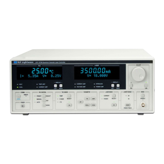
Page 15: Figure 1.3 - Ldc-3736 Front Panel
Figure 1.3 – LDC-3736 Front Panel Figure 1.4 – LDC-3736 Rear Panel December 2019 LDC-3706 Series Laser Controller... -
Page 16: Figure 1.5 - Ldc-37620 Front Panel
Figure 1.5 – LDC-37620 Front Panel Figure 1.6 – LDC-37620 Rear Panel December 2019 LDC-3706 Series Laser Controller... -
Page 17: Options And Accessories
CS Bar Laser Diode Mount LDM-4415 Laser Diode, TO-3 and HHL Mount LDM-4442 Butterfly Laser Diode Mount LDM-49840 2-Pin Module Laser Diode Mount LDM-49860 See Chapter 2, TEC Connections. December 2019 LDC-3706 Series Laser Controller... -
Page 18: Ldc-3706 Specifications
LDC-3706 Specifications December 2019 LDC-3706 Series Laser Controller... - Page 19 December 2019 LDC-3706 Series Laser Controller...
- Page 20 December 2019 LDC-3706 Series Laser Controller...
- Page 21 December 2019 LDC-3706 Series Laser Controller...
- Page 22 December 2019 LDC-3706 Series Laser Controller...
-
Page 23: Chapter 2: General Operation
Check the power switch on the rear panel is in the proper position prior to power up. Damage to internal fuses and other internal circuitry may occur if the wrong line voltage is selected. December 2019 LDC-3706 Series Laser Controller... -
Page 24: The Power Up Sequence
Recall Button descriptions in the Front Panel Operation section of this chapter for more information. Firmware Upgradeability The firmware on the LDC-3706 instrument can be reinstalled or upgraded via USB. Contact ILX Lightwave technical support for information on upgrading the software of the LDC-3706 instrument. December 2019 LDC-3706 Series Laser Controller... -
Page 25: Gpib Communication
The LDC-3706 Laser Controller may be rack mounted by installing the appropriate rack mount flange on either side of the enclosure. All rack mount accessory kits contain detailed mounting instructions. Refer to the Options and Accessories table in Chapter 1 for applicable rack mount accessory part numbers. December 2019 LDC-3706 Series Laser Controller... -
Page 26: Connections
The Current Source output terminals of the LDC-3706 Laser Controller (Laser Anode and Laser Cathode) should never be shorted together or loaded with less than 0.1 Ω. Doing so may result in damage to the instrument. December 2019 LDC-3706 Series Laser Controller... - Page 27 Pin 17 (LDC-3736 & LDC-37620) Pin 18 (LDC-3736 & LDC-37620) 8A Pin 17 to Analog Ground Pins 18 to Analog Ground 5A Pin 17 to Analog Ground Pin 18 N/C 1A Pin 17 N/C Pin 18 N/C December 2019 LDC-3706 Series Laser Controller...
- Page 28 LDC-3706, a TTL level trigger output is provided through a grounded, female BNC connector on the rear of the instrument. For further information please consult the Specifications section of Chapter 1. December 2019 LDC-3706 Series Laser Controller...
-
Page 29: Connecting To The Laser Controller
(such as through the laser package and mount), the user must be careful to avoid multiple earth ground in the circuit. Multiple earth grounds may provide circuit paths that induce spurious currents in the photodiode feedback circuit and output leads. Figure 2.1 - Laser Diode Connection Configurations December 2019 LDC-3706 Series Laser Controller... - Page 30 3-pin lasers (where the common connection is internal to the device). A 4-pin laser should be connected with the same shielding as shown in Figure 2.1. It is recommended that the laser and photodiode remain isolated when possible. December 2019 LDC-3706 Series Laser Controller...
-
Page 31: Front Panel Operation
GPIB address, enter Save or Recall bin numbers or enter instrument calibration data. The enable button LEDs indicate the three modes of operation of the knob: Disabled (both LEDs off), TEC adjustment enabled (TEC LED on), and LASER adjustment enabled (LAS LED on). December 2019 LDC-3706 Series Laser Controller... -
Page 32: Parameters Setup
Calibration: This menu allows calibration of sensor readings (10 µA thermistor, 100 µA thermistor, 1 mA RTD, 2.5 mA RTD, ICI, and ICV), TEC current output and readings, and TEC voltage readings. See Chapter 5 for more details. December 2019 LDC-3706 Series Laser Controller... -
Page 33: Pid Temperature Control
When a preset has been selected for a mount, the LDC-3706 will set the PID values, sensor type, and current limits. Models Presets All LDC-3706 Models GAIN1, GAIN3, GAIN10, GAIN 30, GAIN100, GAIN300 LDC-3726 Only LDM4405, LDM4980, LDM4990, 710 LDC-3736 Only LDM4872 LDC-37620 Only LDM49840, LDM49860 December 2019 LDC-3706 Series Laser Controller... - Page 34 Reaching any output off enable condition (such as temperature or voltage limits) during the auto-tune operation. If the auto-tune algorithm fails for a particular thermal system, it may be necessary to modify the PID coefficients manually. December 2019 LDC-3706 Series Laser Controller...
-
Page 35: Temperature Control Mode
Limits: The limits for the Laser Current source are divided into three different limits which are accessible at the top of the laser menu: Laser Current Limit Laser Voltage Limit Laser Power Limit December 2019 LDC-3706 Series Laser Controller... - Page 36 BNC input port on the front of the instrument, make sure that the Modulation State is set to the OFF condition by pressing the Enable button until the ENABLE LED is unlit. December 2019 LDC-3706 Series Laser Controller...
-
Page 37: Current Control Mode
RIGHT Button (Right) – Cycles right-half of the right-hand (Laser) display through the available laser current source measurement and setpoint parameters that can be displayed When the same parameter is displayed on the left and right display the LDC-3706 will provide the maximum resolution allowed. December 2019 LDC-3706 Series Laser Controller... -
Page 38: Error Indicators
To achieve the rated accuracy, allow the LDC-3706 instrument to warm-up for at least one hour before use. Always operate the controller within the environmental limits specified in the Specifications section of Chapter 1. The best accuracy is achieved near the calibration temperature of 23°C. December 2019 LDC-3706 Series Laser Controller... -
Page 39: Operating The Laser Current Source From The Front Panel
8. The user can display measured voltage, photodiode current, calculated photodiode power, and current setpoint on either the left or right side of the LASER display by pressing the LEFT or RIGHT display soft buttons under the LASER display. December 2019 LDC-3706 Series Laser Controller... - Page 40 9. The user can display measured voltage, photodiode current, calculated photodiode power, and current setpoint on either the left or right side of the LASER display by pressing the LEFT or RIGHT display soft buttons under the LASER display. December 2019 LDC-3706 Series Laser Controller...
- Page 41 8. The user can display measured voltage, photodiode current, photodiode power set point, and measured current in either the left or right side of the LASER display by pressing the LEFT or RIGHT display soft buttons under the LASER display. December 2019 LDC-3706 Series Laser Controller...
-
Page 42: Using The Ldc-3706 Controller's Trigger Output Function
A grounded female BNC connector on the rear panel of the LDC-3706 Laser Controller is available for connecting any standard BNC terminated cable and connecting to equipment that can accept the levels produced by the LDC-3706 instrument trigger out signal. December 2019 LDC-3706 Series Laser Controller... -
Page 43: Operating The Temperature Controller From The Front Panel
10 µA or 100 µA in the front panel TEC parameter menu. Using 10 µA as the thermistor current allows a maximum thermistor resistance of 450 kΩ to be used. The 100 µA setting allows a 45 kΩ maximum. December 2019 LDC-3706 Series Laser Controller... -
Page 44: Figure 2.4 - Example Thermistor Resistance Vs. Temperature
Notice also that the lower slope of the curve at the higher temperatures results in a smaller feedback signal. If higher temperatures are being controlled, it may be necessary to use a thermistor with a different curve. Figure 2.4 - Example Thermistor Resistance vs. Temperature December 2019 LDC-3706 Series Laser Controller... - Page 45 PARAM menu. The sensor will have approximately 1 mA of current through it at all times. In IC-V sensor mode, the LDC-3706 instrument has a sensor voltage limit of 6 V, which is approximately 325°C. December 2019 LDC-3706 Series Laser Controller...
- Page 46 100 Ω RTD than that of a typical 10 kΩ thermistor. The proportional and integral terms for the PID loop must be increased appropriately when using an RTD sensor for optimal setting time and stability. December 2019 LDC-3706 Series Laser Controller...
-
Page 47: Safety Limits
LD TEC error link is enabled) and generates an error on the TEC display. Additionally, setting the positive current limit to a lower value will reduce the likelihood of thermal runaway. December 2019 LDC-3706 Series Laser Controller... -
Page 48: Constant Temperature Mode Operation
7. Enable the TEC output of the LDC-3706 by pressing the ON soft button (left) in the TEC MODE section of the front panel. This button has a toggling action so pressing this button once more will disable the TEC output. December 2019 LDC-3706 Series Laser Controller... -
Page 49: Constant Sensor Mode Operation
7. Enable the TEC output of the LDC-3706 by pressing the ON soft button (left) in the TEC MODE section of the front panel. This button has a toggling action so pressing this button once more will disable the TEC output. December 2019 LDC-3706 Series Laser Controller... -
Page 50: Constant Current Mode Operation
7. Enable the TEC output of the LDC-3706 instrument by pressing the ON soft button (left) in the TEC MODE section of the front panel. This button has a toggling action so pressing this button once more will disable the TEC output December 2019 LDC-3706 Series Laser Controller... -
Page 51: Resistive Heater Mode Operation
7. Enable the TEC output of the LDC-3706 by pressing the ON soft button (left) in the TEC MODE section of the front panel. This button has a toggling action so pressing this button once more will disable the TEC output December 2019 LDC-3706 Series Laser Controller... - Page 52 December 2019 LDC-3706 Series Laser Controller...
-
Page 53: Chapter 3: Remote Operation
Depending on its content, data is often called a “device dependent message” or a “device dependent command”. Interface messages manage the bus, with functions such as initializing the bus and addressing or un-addressing devices. In addition, some individual bus lines are designated for this purpose. December 2019 LDC-3706 Series Laser Controller... -
Page 54: Talkers, Listeners, And Controllers
Up to 15 devices may be connected to the bus. The maximum length of cable used should be limited to 20m. Caution should be taken if individual cable lengths exceed 4m. Figure 3.1 – GPIB Cable Connection December 2019 LDC-3706 Series Laser Controller... -
Page 55: The Gpib Connector
SRQ (service request) can be set by any device in the system to request service from the controller. EOI (end or identify) is used by talkers to identify the end of a message. December 2019 LDC-3706 Series Laser Controller... -
Page 56: Reading The Gpib Address
GPIB specific operations. USBTMC allows instrument manufacturers to upgrade the physical layer from GPIB to USB while maintaining software compatibility with existing software, such as instrument drivers and any application that uses VISA. December 2019 LDC-3706 Series Laser Controller... -
Page 57: Changing Between Local And Remote Operation
Some examples of what works and what does not are shown below. Table 3.1 – Acceptable and Not Acceptable Spelling ACCEPTABLE NOT ACCEPTABLE DISP DISPlay or DISPLAY Displa or DISPL December 2019 LDC-3706 Series Laser Controller... -
Page 58: White Space
The semicolon can be preceded by one or more spaces. For example: DISPLAY ON;*IDN?;READ? DISPLAY ON ; *IDN?; READ? Parameters Some commands require a parameter. The parameter must be separated by at least one white space. December 2019 LDC-3706 Series Laser Controller... - Page 59 For further clarity in programming, the Boolean values of one (1) and zero (0) may be used. Other acceptable names are indicated in Table 3.5. Parameters of a Boolean type are sometimes referred to as <bool>. Table 3.5 – Substitute Parameter Values SUBSTITUTE NAME VALUE December 2019 LDC-3706 Series Laser Controller...
-
Page 60: Syntax Summary
Missing colon between “LIM” and “HIGH”. Missing semicolon; ”SYST:VERS” command causes an OUTPUT ON SYST:VERS? error. DISPLAY ? Space not allowed before question mark. Space missing between “LIM” command and the SOURCE:POW:LIM1.2 parameter value 1.2. December 2019 LDC-3706 Series Laser Controller... -
Page 61: Ieee 488.2 Common Commands
Numeric data is required with *RCL (0 – 10, see front panel RECALL function), *SAV (1 – 10, see front panel STORE function), and *ESE (0 – 255, see Figure 3.4 – Status Reporting Scheme). December 2019 LDC-3706 Series Laser Controller... -
Page 62: Command Timing
See the Operation Complete Definition in chapter 4 for conditions about setting the operation complete flag. December 2019 LDC-3706 Series Laser Controller... -
Page 63: Sequential / Overlapped Commands
Query responses are evaluated at the time the query request is parsed, and not at the time the response message is sent. In most cases, this does not create a problem since the time between parsing a query and sending its response is small. December 2019 LDC-3706 Series Laser Controller... - Page 64 December 2019 LDC-3706 Series Laser Controller...
-
Page 65: Chapter 4: Command Reference
“INSTrument LAS” or “INSTrument TEC”. Some commands listed in Table 4.2 operate on only one logic instrument while some operate on both as identified by the column on the right. December 2019 LDC-3706 Series Laser Controller... - Page 66 Sets the Service Request Enable Register bits to allow generation of user-selectable service requests. *SRE? Returns the current contents of the Service Request Enable Register. *STB? Returns the current contents of the Status Byte Register. *WAI Prevents executing any further commands until the No-Operation-Pending flag is true. December 2019 LDC-3706 Series Laser Controller...
- Page 67 CALCulate:TRANsform:TEMPerature:SHHart:A <nrf> resistance to temperature equation for thermistors. Report coefficient A in Steinhart- CALCulate:TRANsform:TEMPerature:SHHart:A? Hart resistance to temperature equation for thermistors. Set coefficient B in Steinhart-Hart resistance to temperature equation CALCulate:TRANsform:TEMPerature:SHHart:B <nrf> for thermistors. December 2019 LDC-3706 Series Laser Controller...
- Page 68 Send measured RTD resistance to 2.5 CALibrate:RTD2500UA:DATA <nrf> mA RTD calibration procedure. Execute ICI sensor current CALibrate:SENSORI:STARt calibration procedure. Perform ICV sensor voltage CALibrate:SENSORV:STARt measurement calibration. Send measured ICV sensor voltage to CALibrate:SENSORV:DATA <nrf> sensor voltage calibration procedure. December 2019 LDC-3706 Series Laser Controller...
- Page 69 TE controller instrument operating modes. Reports currently selected INSTrument:NSELect? instrument operating mode. Selects between Laser current INSTrument[:SELect] <string> source or TE controller instrument operating modes. Reports currently selected INSTrument[:SELect]? instrument operating mode. December 2019 LDC-3706 Series Laser Controller...
- Page 70 Report photodiode current MEASure[:SCALar]:CURRent2? measurement. Report photodiode power MEASure[:SCALar]:POWer? measurement. MEASure[:SCALar]:TEMPerature? Report temperature measurement. Report LDV or VTE, depending on the MEASure[:SCALar]:VOLTage? LAS, TEC currently selected instrument mode. Report the currently-selected MEASure:SENSor? sensor measurement. December 2019 LDC-3706 Series Laser Controller...
- Page 71 Report high voltage limit for IC SENSor:ICV:LIMit:HIGH? sensor. SOURce[1]:AM[:STATE] <nrf> Enable or disable LDI modulation. Report currently selected LDI SOURce[1]:AM[:STATE]? modulation state. SOURce[1]:CURRent:LIMit:HIGH <nrf> Set upper TEC current limit. SOURce[1]:CURRent:LIMit:HIGH? Report upper TEC current limit. December 2019 LDC-3706 Series Laser Controller...
- Page 72 Report the TE controller resistance SOURce[1]:RESistance:PROTection:LOW? lower limit. Set the TE controller resistance SOURce[1]:RESistance:PROTection[:HIGH] <nrf> upper limit. Report the TE controller resistance SOURce[1]:RESistance:PROTection[:HIGH]? upper limit. SOURce[1]:RESistance:SPOint <nrf> Set the TE controller resistance December 2019 LDC-3706 Series Laser Controller...
- Page 73 SOURce[1]:TEMPerature:TOLerance? Report TEC temperature tolerance. Set duration for temperature to be SOURce[1]:TOLerance:TIME <nrf> stable. Report duration for temperature to SOURce[1]:TOLerance:TIME? be stable. Report if temperature has settled SOURce[1]:STABle? to user-specified temperature and time window. December 2019 LDC-3706 Series Laser Controller...
- Page 74 Report the number of errors in the SYSTem:ERRor:COUNt? error queue. SYSTem:ERRor[:NEXT]? Report next error from error queue. Purge error queue, reset laser SYSTem:PREset controller and TE controller to default settings. Report currently installed firmware SYSTem:VERSion? version. December 2019 LDC-3706 Series Laser Controller...
-
Page 75: Command Reference
See *ESR? for a description of each bit in the status register along with a diagram of the reporting structure Examples *ESE? A response of 68 means the user request and query error bits have been enabled in the standard event status enable register (68 = 2 December 2019 LDC-3706 Series Laser Controller... - Page 76 Requests the instrument to identify itself Notes Returns a string of instrument identification information. The string contains a comma separated list of manufacturer, model number, serial number, and firmware revision. Examples *IDN? Responds with “ILX Lightwave,LDC-3706,37061111,1.00-1.00” December 2019 LDC-3706 Series Laser Controller...
- Page 77 Stops operation of overlapped commands Sets all device specific function to a known state (*RST Value) The reset command does NOT affect the following: Output Queue Enable Registers Event Registers *PSC state Memory contents associated with *SAV December 2019 LDC-3706 Series Laser Controller...
- Page 78 The response is a value between 0 and 255, representing the bits of the standard event status enable register when expressed in base 2 binary format Examples *SRE? A response of 16 signifies that the message available summary bit is enabled December 2019 LDC-3706 Series Laser Controller...
- Page 79 Care should be taken to set the time-out appropriately for use with the *WAI command. After this command is sent, the instrument may block subsequent commands waiting for the input queue to empty. Examples :OUTPUT ON;*WAI;:MEAS:T? The temperature measurement will occur after the output is on December 2019 LDC-3706 Series Laser Controller...
- Page 80 The Callendar-Van Dusen equation: − 100 ( < 0 °C) ( ≥ 0 °C) Where is the resistance at temperature . Reset Value -4.183 Example CALC:TRAN:TEMP:CVD:C -4.183; Sets CVD:B to -4.183 x 10 °C December 2019 LDC-3706 Series Laser Controller...
- Page 81 CALCulate:TRANsform:TEMPerature:ICV[:GAIN] <nrf> TEC CALCulate:TRANsform:TEMPerature:ICV[:GAIN]? Description Sets/Reports slope compensation for a temperature to voltage transducer. Parameters -99.99 – 99.99 – The compensating slope. Reset Value 10.0 Example CALC:TRAN:TEMP:ICV 10.0; Sets the ICV sensor slope to 10. December 2019 LDC-3706 Series Laser Controller...
- Page 82 CALibrate:CURR100UA:DATA <nrf> TEC Description Send data point for the 100 µA thermistor calibration procedure. Parameters DATA – a number representing the actual current in Amps Example CAL:CURR100UA:DATA 0.01; Sends a data point of 0.01A. December 2019 LDC-3706 Series Laser Controller...
- Page 83 DATA – a number representing the actual current in Amps Notes This is the same as CALibrate:PDI:STARt and CALibrate:PDI[:DATA] below; there are two versions for user flexibility Example CAL:MDI:DATA 0.0005; Sends a data point of 0.0005A. December 2019 LDC-3706 Series Laser Controller...
- Page 84 CAL:RTD2500UA:DATA 250; Sends a data point of 250Ω. CALibrate:SENSORI:STARt TEC Description Execute the TE ICI sensor current calibration procedure. Notes There must be nothing connected to the sensor pins. CALibrate:SENSORV:STARt TEC Description Begins the TE ICV sensor voltage calibration procedure. December 2019 LDC-3706 Series Laser Controller...
- Page 85 DISP:BRIG 5; Changes the brightness to 5. DISPlay[:ENABle] <nrf> N/A DISPlay[:ENABle]? Description Sets/Reports on/off state of the front panel displays. Parameters 0 or 1 – 0 for off, 1 for on Reset Value Example DISP 1; Turns the display on. December 2019 LDC-3706 Series Laser Controller...
- Page 86 Reports the selected instrument’s Condition status register. See chapter 3, Status Reporting. Example COND? A response of 1025 (bits 10 and 0 set) indicates the output is on and the laser is in current limit. December 2019 LDC-3706 Series Laser Controller...
- Page 87 Example EVE? A response of 8 (bit 3 set) indicates that a Over High T or R Limit condition occurred since the last read of the Event register. December 2019 LDC-3706 Series Laser Controller...
- Page 88 INP:FILT 0; Sets the laser current filter to low pass. INSTrument:CATalog? N/A Description Reports the possible instrument mode selections for the LDC-3706. Response Responds with the string “LAS, TEC”, the two possible operating modes for the LDC-3706. December 2019 LDC-3706 Series Laser Controller...
- Page 89 Sets/Reports the ending current for LIV. Parameters End point in Amps. LDC-3726 0 – 0.5 LDC-3736 0 – 4 LDC-37620 0 – 20 Reset Value LDC-3726 LDC-3736 LDC-37620 Example LIV:ENDLDI 0.5; Sets the ending current for LIV to 0.5A. December 2019 LDC-3706 Series Laser Controller...
- Page 90 This command will output LIV:READCOUNT points, starting at the value specified for LIV:DATA? <nrf>. Example LIV:DATA? 5; (Assuming LIV:READCOUNT 10, 15 total points) , LDI , LDV , MDI , LDI , LDV … MDI , LDI , LDV December 2019 LDC-3706 Series Laser Controller...
- Page 91 TEC controller mode. MEASure:SENSor? TEC Description Reports the currently selected sensor’s native quantity. For a resistive sensor, response value is in ohms. For ICI, response is in uA. For ICV, response is in mV. December 2019 LDC-3706 Series Laser Controller...
- Page 92 LDM49840, LDM49860, DEFAULT Notes Refer to Chapter 2, PID Temperature Control, for parameter values for each preset. Reset Value LDM-3726 LDM-3736 LDM-37620 LDM4872 GAIN1 GAIN1 Example PID:PRESET GAIN10; Sets the PID preset to GAIN10. December 2019 LDC-3706 Series Laser Controller...
- Page 93 SENSor:ICV:SETpoint <nrf> TEC SENSor:ICV:SETpoint? Description Sets/Reports voltage setpoint for the IC sensor. Parameters 0 – 6.0 – Range in Volts. Reset Value Example SENS:ICV:SET 0; Sets the voltage setpoint for the IC sensor to 0V. December 2019 LDC-3706 Series Laser Controller...
- Page 94 Parameters Lower current limit in Amps LDC-3726 0.00 – -4.00 LDC-3736 0.00 – -8.00 LDC-37620 0.00 – -8.00 Reset Value -1.00 Example SOUR:CURR:LIM:LOW -4; Sets the lower current limit for the TEC to -4A. December 2019 LDC-3706 Series Laser Controller...
- Page 95 LDC-37620 Laser Laser Laser 0.00 – 0.500 -4.00 – +4.00 0.00 – 4.00 -8.00 – +8.00 0.00 – 20.00 -8.00 - +8.00 Example SOUR:CURR 4; Sets the current for the selected instrument to 4A. December 2019 LDC-3706 Series Laser Controller...
- Page 96 Sets/reports integral term for TEC controller PID loop in sensor mode. See Chapter 2 for a summary of PID control. Parameters 0.000000 – 10.000000 – Integral value setting Reset Value Example SOUR:RES:LCON:INT 0.1; Sets the integral term for resistance to 0.1. December 2019 LDC-3706 Series Laser Controller...
- Page 97 The bit will also be set if the measured resistance is less than this amount below the setpoint. Parameters 0.00 – 500000.0 – Tolerance in Ω Reset Value 5000.0 Example SOUR:RES:TOL 7500.0; Sets the resistance tolerance to 7.5kΩ. December 2019 LDC-3706 Series Laser Controller...
- Page 98 SOUR:TEMP:LCON 15; Sets the proportional term for temperature mode to 15. SOURce[1]:TEMPerature:PROTection:LOW <nrf> TEC SOURce[1]:TEMPerature:PROTection:LOW? Description Sets/reports low limit for temperature. Parameters -100.00 – 200.00 – Low temperature limit in ˚C. Reset Value Example SOUR:TEMP:PROT:LOW 0; Sets the lower limit for temperature to 0ºC. December 2019 LDC-3706 Series Laser Controller...
- Page 99 Reports if the temperature has settled to user-specified temperature and time window. SOURce[1]:VOLTage:LIMit <nrf> LAS SOURce[1]:VOLTage:LIMit? Description Sets/reports laser diode compliance voltage maximum limit. Parameters 0.000 – 18.000 – Maximum voltage in Volts. Reset Value 9.000; Sets the compliance voltage to 9V. December 2019 LDC-3706 Series Laser Controller...
- Page 100 Reports the number of errors in the error queue. SYSTem:ERRor[:NEXT]? N/A Description Reports the first error and removes it from the error queue. SYSTem:PRESet N/A Description Resets laser controller and TE controller to default settings. December 2019 LDC-3706 Series Laser Controller...
- Page 101 December 2019 LDC-3706 Series Laser Controller...
-
Page 102: Chapter 5: Troubleshooting And Calibration
Calibration turn-around times are normally five business days or less. Please contact ILX Customer Support (see Comments, Suggestions, and Problems on page ix for contact information) for additional calibration information. For further assistance with technical solutions and troubleshooting, visit us online at www.newport.com/b/ilx-lightwave. December 2019 LDC-3706 Series Laser Controller... -
Page 103: Troubleshooting Guide
GPIB function. The LDC-3706 instrument is not being Check the USB cable connection between the LDC-3706 recognized by USB and the computer. Ensure proper drivers are installed. December 2019 LDC-3706 Series Laser Controller... - Page 104 Remove all other instruments from the GPIB bus to isolate the LDC-3706. If this corrects the problem, re-connect one instrument at a time until the problem returns. Then check the other instrument for address conflicts and proper GPIB function. December 2019 LDC-3706 Series Laser Controller...
- Page 105 The LDC-3706 has an adjustable laser compliance voltage. error E505 prevents output from Check to see if the LASER voltage limit setting is too low reaching desired value. (see Chapter 2). Check laser connections. December 2019 LDC-3706 Series Laser Controller...
- Page 106 Inaccurate sensor, TEC voltage, or TEC Insure the 4-wire TEC sensor connections (pins 7 and 8) are current measurement on the LDC-3706. connected. For thermistor or RTD sensors insure the 4-wire sensor connections (pins 1 and 2) are connected. December 2019 LDC-3706 Series Laser Controller...
-
Page 107: Error Messages
Configuration memory has been lost. -320 A storage fault has occurred. -321 The device is out of memory. -340 The calibration procedure has failed. -341 The calibration data entered is invalid. -342 The measurement calibration has failed. December 2019 LDC-3706 Series Laser Controller... - Page 108 TEC open circuit error. TEC temperature limit error. General TEC programming error. Laser interlock error. Laser open circuit error. Laser over current error. Laser temperature out of range error. Unknown laser board detected. Laser over power. December 2019 LDC-3706 Series Laser Controller...
-
Page 109: Calibration Overview
LDC-3706 instrument may be calibrated at its intended use temperature if this is within the specified operating temperature range of 10 to 40°C. Warm-up The LDC-3706 instrument should be allowed to warm-up for at least 1 hour before calibration unless otherwise specified. December 2019 LDC-3706 Series Laser Controller... -
Page 110: Calibration Adjustments
4. Press the TEC button and wait for the 7-segment display to exit the calibration mode. Once the calibration is completed, the calibration constants will be stored to the non- volatile memory and the display will return to its previous state. December 2019 LDC-3706 Series Laser Controller... -
Page 111: Ic-I (Ad590 Or Equivalent) Sensor Calibration
7. Press the TEC button and wait for the 7-segment display to exit the calibration mode and reflect the entered sensor resistance setpoint. Once the calibration is completed, the calibration constants will be stored to the non-volatile memory and the display will return to its previous state. December 2019 LDC-3706 Series Laser Controller... -
Page 112: Rtd Sensor Calibration
8. Wait for the 7-segment display to exit the calibration mode and reflect the entered sensor resistance setpoint. Once the calibration is completed, the calibration constants will be stored to the non-volatile memory and the display will return to its previous state. December 2019 LDC-3706 Series Laser Controller... -
Page 113: Ite Current Calibration
7. Wait for the 7-segment display to exit the calibration mode. Once the self-calibration is completed and calibration mode is exited, the calibration constants will be stored to the non-volatile memory and the display will return to its previous state. December 2019 LDC-3706 Series Laser Controller... -
Page 114: Laser Driver Current Calibration
6. Wait for the 7-segment display to exit the calibration mode. Once the self-calibration is completed, the calibration constants will be stored to the non-volatile memory and the display will return to its previous state. December 2019 LDC-3706 Series Laser Controller... -
Page 115: Laser Voltage Measurement Calibration
6. The instrument will apply a second current after a short time. Repeat step 5 for the second current. 7. Once the self-calibration is completed and calibration mode is exited, the calibration constants will be stored to the non-volatile memory and the display will return to its previous state. December 2019 LDC-3706 Series Laser Controller... -
Page 116: Photodiode Current Calibration
R is the accurately measured load resistance. 8. Turn the ADJUST knob until the display shows the value of the photodiode current measurement as calculated from step 6. Then press the LAS button. December 2019 LDC-3706 Series Laser Controller... - Page 117 10. Wait for the 7-segment display to exit the calibration mode. Once the self-calibration is completed, the calibration constants will be stored to the non-volatile memory and the display will return to its previous state. December 2019 LDC-3706 Series Laser Controller...
- Page 118 December 2019 LDC-3706 Series Laser Controller...
-
Page 119: Appendix A: Ad590 And Lm335 Sensor Calibration
This non-linearity is shown in Figure A.1, reprinted from Analog Devices specifications, where the error associated with C is assumed to be zero. December 2019 LDC-3706 Series Laser Controller... -
Page 120: Lm335 Sensor
°C. The temperature, T , which is displayed by the LDC-3706, is first calibrated as follows: ∗ Where C and C are the constants stored by the user in the LDC-3706 for the LM335. December 2019 LDC-3706 Series Laser Controller... -
Page 121: One Point Calibration Method
4. Determine the new value of the offset, offset-new, from the formula: − − and replace the previous offset value with the newly calculated value by selecting the offset parameter and entering the offset-new value. December 2019 LDC-3706 Series Laser Controller... -
Page 122: Two Point Calibration Method
+ ( ∗ ∗ 6. Replace C with C by selecting the C parameter and entering the new C value. Replace C with C by selecting the C parameter and entering the new C value. December 2019 LDC-3706 Series Laser Controller... -
Page 123: Appendix B: Auto-Tune Method
1 and point 2. When the temperature exceeds the setpoint temperature at point 1, the current immediately switches to the maximum value, as seen at point 2. Eventually, the December 2019 LDC-3706 Series Laser Controller... - Page 124 These values can be altered through the manual PID setting section of the front panel or through remote commands to fine tune performance or to adjust for different set points and operating conditions. December 2019 LDC-3706 Series Laser Controller...
Need help?
Do you have a question about the LDC-3706 Series and is the answer not in the manual?
Questions and answers