Table of Contents
Advertisement
Quick Links
Download this manual
See also:
Manual
Advertisement
Table of Contents

Related Manuals for Newport XPS-Q8


Summary of Contents for Newport XPS-Q8
- Page 1 XPS-Q8 Universal High-Performance Motion Controller/Driver User’s Manual, Software Tools and Tutorial V1.4.x...
- Page 2 Universal High-Performance Motion Controller/Driver Warranty Newport Corporation warrants that this product will be free from defects in material and workmanship and will comply with Newport’s published specifications at the time of sale for a period of one year from date of shipment. If found to be defective during the warranty period, the product will either be repaired or replaced at Newport's option.
-
Page 3: Table Of Contents
General Warnings and Cautions ....................4 2.0 System Overview................... 6 Specifications ........................... 6 Drive Options .......................... 7 Compatible Newport Positioners and Drive Power Consumption ........... 8 XPS Hardware Overview......................9 Front Panel Description ......................9 Rear Panel Description ......................10 2.6.1... - Page 4 3.8.1 Auto Configuration .................... 29 3.8.2 Manual Configuration for Newport Positioners ..........31 3.8.3 Manual Configuration for non Newport stages ..........35 System Shut-Down ........................ 35 Software Tools 4.0 Software Tools..................... 36 Software Tools Overview ...................... 36 CONTROLLER CONFIGURATION – Users Management..........37 CONTROLLER CONFIGURATION –...
- Page 5 XPS-Q8 Universal High-Performance Motion Controller/Driver 4.11 STAGE – Modify ........................ 50 4.12 FRONT PANEL – Move ..................... 52 4.13 FRONT PANEL – Jog ......................53 4.14 FRONT PANEL – Spindle ....................53 4.15 FRONT PANEL – I/O View....................54 4.16 FRONT PANEL –...
- Page 6 XPS-Q8 Universal High-Performance Motion Controller/Driver 7.3.2 Moves of Certain Displacements ............... 80 7.3.3 Position Counter Resets ..................80 7.3.4 State Diagram ....................81 7.3.5 Example: MechanicalZeroAndIndexHomeSearch ..........81 Move ............................81 Motion Done .......................... 83 JOG ............................85 Master Slave .......................... 86 Analog Tracking ........................
- Page 7 XPS-Q8 Universal High-Performance Motion Controller/Driver 9.0 Emergency Brake and Emergency Stop Cases ........108 10.0 Compensation..................111 10.1 Backlash Compensation ..................... 112 10.2 Linear Error Correction ..................... 113 10.3 Positioner Mapping ......................113 10.4 XY Mapping ........................116 10.5 XYZ Mapping ........................118 10.6...
- Page 8 XPS-Q8 Universal High-Performance Motion Controller/Driver 15.0 Analog Encoder Calibration ..............185 16.0 Excitation Signal ..................190 16.1 Introduction........................190 16.2 How to Use the Excitation-Signal Function ..............190 16.3 Group State Diagram ......................191 16.4 Function Description......................191 17.0 Pre-Corrector Excitation Signal ............192 17.1...
- Page 9 XPS-Q8 Universal High-Performance Motion Controller/Driver Appendix 19.0 Appendix A: Hardware............... 204 19.1 Controller ........................... 204 19.2 Rear Panel Connectors ....................... 205 19.3 Environmental Requirements..................... 205 20.0 Appendix B: General I/O Description ..........206 20.1 Digital I/Os (All GPIO, Inhibit and Trigger In, and PCO Connectors) ....... 206 20.1.1...
-
Page 10: Eu Declaration Of Conformity
XPS-Q8 Universal High-Performance Motion Controller/Driver EU Declaration of Conformity XPSDocumentation V1.4.x (EDH0301En1060 — 10/17) -
Page 11: Preface
Customer shall protect the Newport Programs and Related Materials as trade secrets of Newport, and shall devote its best efforts to ensure that all its personnel protect the Newport Programs as trade secrets of Newport Corporation. Customer shall not at any... - Page 12 • Can you identify anything that may have caused the problem? Newport Corporation RMA Procedures Any XPS Series Controller/Driver being returned to Newport must be assigned an RMA number by Newport. Assignment of the RMA requires the item’s serial number.
-
Page 13: User's Manual
XPS-Q8 Controller User’s Manual User’s Manual Introduction Scope of the Manual The XPS is an extremely high-performance, easy to use, integrated motion controller/driver offering high-speed communication through 10/100 Base-T Ethernet, outstanding trajectory accuracy and powerful programming functionality. It combines user-friendly web interfaces with advanced trajectory and synchronization features to precisely control from the most basic to the most complex motion sequences. - Page 14 XPS-Q8 Controller User’s Manual The second part provides a detailed description of all software tools of the XPS controller. It also includes an introduction to FTP connections and some general guidelines for troubleshooting, maintenance and service: 4. Software Tools 5. FTP connection 6.
-
Page 15: Definitions And Symbols
European Union CE Mark Figure 3: CE Mark. The presence of the CE Mark on Newport Corporation equipment means that it has been designed, tested and certified to comply with all current and applicable European Union (CE) regulations and recommendations. -
Page 16: Warnings And Cautions
XPS-Q8 Controller User’s Manual Warnings and Cautions The following are definitions of the Warnings, Cautions and Notes that may be used in this manual to call attention to important information regarding personal safety, safety and preservation of the equipment, or important tips. - Page 17 • Do not open the XPS Controller/Driver stand alone motion controller. There are no user-serviceable parts inside the XPS Controller/Driver. • Return equipment to Newport Corporation for service and repair. • Dangerous voltages associated with the 100–240 VAC power supply are present inside Controller/Driver unit.
-
Page 18: System Overview
XPS-Q8 Controller User’s Manual System Overview Specifications Number of Axes • 1 to 8 axes of stepper, DC brush, DC brushless motors or piezo-electric stacks using internal drives • Other motion devices using external third-party drives Communication Interfaces • Internet protocol TCP/IP •... -
Page 19: Drive Options
• 15 kg max Drive Options The XPS controller is capable of driving up to 8 axes of most Newport positioners using driver cards that slide through the back of the chassis. These factory-tested drives are powered by an internal 500 W power supply, which is independent of the controller power supply. -
Page 20: Compatible Newport Positioners And Drive Power Consumption
Furthermore, the XPS-DRV03 features individual limits for the rms current and the peak current. The XPS-DRVP1 is a programmable driver card for Newport's NanoPositioning line of piezoelectric stack stages. This driver card has a range of -10 to 150 VDC with 30 mA continuous. -
Page 21: Xps Hardware Overview
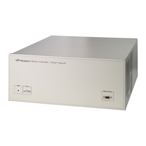
XPS-Q8 Controller User’s Manual XPS Hardware Overview Figure 6: XPS Hardware Overview. Front Panel Description Figure 7: Front Panel of XPS Controller/Driver. The XPS-RC Remote Control plugs into the front panel of the XPS controller to enable computer-independent motion and basic system diagnostics. For more information, refer to the XPS data sheet and the XPS-RC manual. -
Page 22: Rear Panel Description
Axis Connectors (AXIS 1 – AXIS 8) Each installed axis driver card features a connector to attach a cable (supplied with every Newport stage) between the controller and a motion device. CAUTION Carefully read the labels on the driver cards and make sure the specifications (motor type, voltage, current, etc.) match those of the... -
Page 23: Ethernet Configuration
XPS-Q8 Controller User’s Manual Figure 9: Axis Driver Card. Please see the next section for installation instructions. NOTE Power Input: 100–240 V, 50–60 Hz, 11 A–5.5 A. Ethernet Configuration Figure 10: Ethernet Configuration. 2.7.1 Communication Protocols The Ethernet connection provides a local area network through which information is transferred in units known as packets. -
Page 24: Addressing
XPS-Q8 Controller User’s Manual 2.7.2 Addressing There are two levels of addresses that define Ethernet devices. The first is the MAC address. This is a unique and permanent 6 byte number. No other device will have the same MAC address. The second level of addressing is the IP address. This is a 32-bit (or 4 byte) number. - Page 25 XPS-Q8 Controller User’s Manual one million users. It is quickly becoming a standard and critical component in thousands of corporations. Consequently TCL is field proven, very well documented and has many tutorials, applications, tools and books publicly available (www.tcl.tk). XPS users can use TCL to write complete application code and the XPS allows them to include any function in a TCL script.
-
Page 26: Getting Started
XPS Controller/Driver has been carefully packaged at the factory to minimize the possibility of damage during shipping. Inspect the box for external signs of damage or mishandling. Inspect the contents for damage. If there is visible damage to the equipment upon receipt, inform the shipping company and Newport Corporation immediately. WARNING Do not attempt to operate this equipment if there is evidence of shipping damage or you suspect the unit is damaged. -
Page 27: Installing Driver Cards
XPS-Q8 Controller User’s Manual 3.4.1 Installing Driver cards Figure 11: Installing Driver cards. Due to the high power of the XPS controller (300 W for the CPU and 500 W for the drives), ventilation is very important. To ensure a good level of heat dissipation, the following rules must be followed: 1. -
Page 28: Connecting To The Xps
User’s Manual Connecting to the XPS The Newport’s XPS Controller/Driver is a multi-axis motion controller system that is based on a high performance 10/100 Base-T Ethernet connection using a CAT5 cable. The controller can be connected in 2 different ways: 1. -
Page 29: Direct Connection To The Xps Controller
XPS-Q8 Controller User’s Manual 3.5.3 Direct Connection to the XPS Controller For a direct connection between a PC and the XPS controller you need to use the crossover cable and the HOST or REMOTE connector at the back of the XPS. - Page 30 XPS-Q8 Controller User’s Manual 5. Click “OK”. NOTE The The Last number of the IP address must be set to any number between 2 to 253: 100 for example. NOTE When configuring the controller to be on the network, the settings for the PC’s Ethernet card will have to be set back to default under “Obtain an IP address...
-
Page 31: Connecting The Xps To A Corporate Network Using Static Ip Configuration
XPS-Q8 Controller User’s Manual Once logged in, the XPS has established a direct connection to the local computer. If you don’t want to connect the XPS controller through a Corporate Network you may skip to section 3.7: “Connecting the Stages“. - Page 32 XPS-Q8 Controller User’s Manual NOTE To avoid conflict with the REMOTE Ethernet plug, the IP address must be different from 192.168.254… NOTE For the majority of Networks, the setting above for the Subnet Mask will work. However, for larger networks (200 computers or more), the Subnet Mask address must be verified with the IT department.
-
Page 33: Configuring The Xps For Connection To A Corporate Network Using Dynamic Ip Configuration
XPS-Q8 Controller User’s Manual 3.5.5 Configuring the XPS for Connection to a Corporate Network Using Dynamic IP Configuration It is recommended to ask your IT department to configure the XPS to your network to avoid any issue with your network policies and rules. - Page 34 XPS-Q8 Controller User’s Manual Wait for controller to reboot, open the internet browser and connect to REMOTE You can see the dynamic IP address in CONTROLLER CONFIGURATION => General The IP address delivered by your DHCP is displayed above. In case the XPS cannot negotiate an IP address from the DHCP the displayed address will be 0.0.0.0.
- Page 35 XPS-Q8 Controller User’s Manual Remove the REMOTE cable and, if needed, configure your PC back to its original Ethernet configuration, you have saved before modification. Make sure that the standard CAT-5 network cable (black) is connected to the HOST connector of the XPS controller and to your network.
-
Page 36: Recovering A Lost Ip Configuration
XPS-Q8 Controller User’s Manual 3.5.6 Recovering a lost IP configuration If you want to recover a lost IP configuration, you need to connect the PC directly to the REMOTE connector at the back of the XPS with the gray cross-over cable. - Page 37 XPS-Q8 Controller User’s Manual 5. Click “OK”. NOTE The last number of the IP address must be set to any number between 2 to 253: 100 in this example. NOTE When configuring the controller to be on the network, the settings for the PC’s Ethernet card must be set back to default which is “Obtain an IP address...
-
Page 38: Testing Your Xps-Pc Connection And Communication
XPS-Q8 Controller User’s Manual Once you are logged in, you can change the IP configuration by following the steps described in section 3.5.4 or 3.5.5 depending on your configuration. NOTE If you want to reset the IP address to the default factory setting, follow the section 3.5.4 to set the IP address back to 192.168.0.254. -
Page 39: Connecting The Stages
For a dummy stage, use a male 25-pin D-Sub connector with the signals for + and - travel limits connected to ground, and plug this connector to the Newport stage interface (see pinout description of the motor driver connectors in appendix F). Configure your system with a number of these dummy stages. -
Page 40: Configuring The Controller
XY or XYZ compensation). To take full benefit of the capabilities of the XPS controller, a manual configuration is needed. • For non-Newport stages or very old Newport stages, manual configuration is required. See document ConfigurationWizard.pdf for details. This document is accessible from the XPS web tools under the tab DOCUMENTATION. -
Page 41: Auto Configuration
XPS-Q8 Controller User’s Manual 3.8.1 Auto Configuration When logged in as Administrator, select SYSTEM, then “Auto configuration”. The following screen appears: If you want to continue, click the "Yes, I confirm" button and the following page appears: Check, if all connected stages are recognized by the system. If yes, click “GENERATE CONFIGURATION FILES”. - Page 42 XPS-Q8 Controller User’s Manual Click “Initialize”. The State number changes from 0 to 42 and the Action button changes from “Initialize” to “Home”. Click “Home”. The stage starts moving to find its reference position. When done, the state number is 11 and the action button changes to disable.
-
Page 43: Manual Configuration For Newport Positioners
Users can assign any name for their stages. The default name is the Newport part number, but in some cases it makes sense to use a different name. This way, for instance, it is possible to add the same set of parameters several times in the stage data base under different stage names. - Page 44 ESP chip inside (see the ESP-compatible sticker on the stage) this box should remain checked. Otherwise, with vacuum compatible stages or with old Newport stages, or with non-Newport stages, uncheck this box. 7. Click on “Add new stage” to add the stage.
- Page 45 XPS-Q8 Controller User’s Manual 11. Enter the positioner names. Any positioner name can be used. In this example the X positioner name is ILS150CC_UPPER. The home sequence can be either “Together” or “X then Y”. The other fields refer to the error compensation (mapping) of the XPS controller, see chapter 10.0...
- Page 46 XPS-Q8 Controller User’s Manual 17. Click on “VALID” to return to the initial screen. 18. Continue the same way with the other motion groups. 19. When done, click on “Create new system.ini file” to complete the System configuration. The controller re-boots and the following message appears: Click on “OK”.
-
Page 47: Manual Configuration For Non Newport Stages
Manual Configuration for non Newport stages For configuring the XPS controller to stages or positioning devices not made by Newport, use the tool “Add Custom Stage” under the main tab STAGE. For detailed information about this tool, please refer to the document ConfigurationWizard.pdf provided under the main tab DOCUMENTATION. -
Page 48: Software Tools
XPS-Q8 Controller Software Tools Software Tools Software Tools Software Tools Overview The XPS software tools provide users a convenient access to the most common features and functions of the XPS controller. All software tools are implemented as a web interface. The advantage of a web interface is that it is independent from the user's operating system and doesn't require any specific software on the host PC. -
Page 49: Controller Configuration - Users Management
XPS-Q8 Controller Software Tools The main tab is displayed across the top of the XPS Motion Controller/Driver main program window, and lists each primary interface option. Each interface option has its own pull-down menu that allows the user to select various options by clicking the mouse's left button. -
Page 50: Controller Configuration - Ip Management
XPS-Q8 Controller Software Tools CONTROLLER CONFIGURATION – IP Management See chapter 3.5 for details. CONTROLLER CONFIGURATION – General This screen provides valuable information about the firmware and the hardware of the controller. It is an important screen for troubleshooting the controller. -
Page 51: System - Error File Display
XPS-Q8 Controller Software Tools SYSTEM – Error file display The Error File Display is another important screen for troubleshooting the XPS controller. When the XPS encounters any error during booting, for instance due to an error in the configuration files or because the configuration is not compatible with the connected hardware, there are entries in the error log file that guides you to correct the error. -
Page 52: System - Auto Configuration
For troubleshooting a system, make sure that you have a copy of the original system.ini file for recovery. Under Driver Model and Stage Model, all motor drivers and Newport ESP compatible stages seen by the XPS controller are listed. This screen also provides valuable information for diagnosing or troubleshooting the system. - Page 53 XPS-Q8 Controller Software Tools 2. Enter the name for each positioner associated with the motion group (StepAxis and ScanAxis in this case). Define the home sequence (“Together” or “XThenY” or “YThenX”). For error compensation, define the name and structure of the correction data, otherwise leave these fields blank.
- Page 54 XPS-Q8 Controller Software Tools Like most gantries, the two positioners are rigidly attached to each other. Hence, all motions, including motor initialization, homing, and emergency stops must be done in perfect synchronization. For details about Gantries and their configuration, please refer to section 4.9.
- Page 55 XPS-Q8 Controller Software Tools NOTE “Generate config files and Boot” deletes the current system.ini file. To create a copy of the current system.ini file, retrieve this from the “..admin\config” folder of the XPS controller. The following screen appears: Click on “OK”.
-
Page 56: System - Manual Configuration - Gantries (Secondary Positioners)
XPS-Q8 Controller Software Tools SYSTEM – Manual Configuration – Gantries (Secondary Positioners) This section is for experienced users of the XPS controller and addresses the configuration of a gantry via a secondary positioner. A gantry is a motion device where two positioners, each of them having a motor, an encoder, limits, etc., are used for a motion in one direction. -
Page 57: Home Search Of Gantries
XPS-Q8 Controller Software Tools Define the plug number for the secondary positioner and the name from the stage data base. The secondary positioner must have common values with the primary positioner for the following parameters: • MaximumVelocity • MaximumAcceleration • HomeSearchMaximumVelocity •... -
Page 58: Gantries With Linear Motors
XPS-Q8 Controller Software Tools The sketch below illustrates this process: Primary Secondary Pos = 0 Pos = End referencing Position Pos = 0 Pos = Index difference Initial position 1) Search home of the Secondary positioner. The primary positioner follows 2) Search home of the Primary positioner. -
Page 59: Gantries With Linear Motors And Variable Force Ratio
• Y Offset for force ratio • Primary Y Motor Force Ratio • Secondary Y Motor Force Ratio A correct definition of these three parameters is not simple. For additional information about this function, please call Newport. XPSDocumentation V1.4.x (EDH0301En1060 — 10/17) - Page 60 XPS-Q8 Controller Software Tools This is an example of a system.ini file with one XY gantry: [GROUPS] SingleAxisInUse = SpindleInUse = XYInUse = MyXYGantry XYZInUse = MultipleAxesInUse = [MyXYGantry] PositionerInUse = X, Y InitializationAndHomeSearchSequence = YThenX XMappingFileName = YMappingFileName = ;--- Gantry Force Ratio parameters...
-
Page 61: Stage - Add From Data Base
4.10 STAGE – Add from Data Base With the help of this screen, a stage from the Newport stage data base can be added to the personal stage data base, called stages.ini. In the lower left corner, you can review the name of the stages that are already in this stage data base. -
Page 62: Stage - Modify
XPS-Q8 Controller Software Tools 4.11 STAGE – Modify This screen allows you to review and modify all parameters of stages included in the stages.ini. Only experienced users should modify these parameters. For the exact meaning of the different parameters, please refer to the document ConfigurationWizard.pdf, accessible from the main tab DOCUMENTATION. - Page 63 XPS-Q8 Controller Software Tools To modify the parameters of a stage, do the following: 1. Select a stage from the list. Click on “Modify”. 2. Scroll down to the section that contains the parameters that will be modified. Parameters that require quite common changes, are the minimum and the maximum target positions of a rotation stage.
-
Page 64: Front Panel - Move
XPS-Q8 Controller Software Tools 4.12 FRONT PANEL – Move The Move page provides access to basic group functions like initialize, home, or motor disable, and executes relative and absolute moves. The Move page also provides a convenient review of all important group information like group names, group states and positions. -
Page 65: Front Panel - Jog
XPS-Q8 Controller Software Tools 4.13 FRONT PANEL – Jog The Jog page allows executing a jog motion. A jog motion is a continuous motion, where only the speed and acceleration are defined, but no target position. Speed and acceleration can be changed during the motion (but not during the acceleration period). -
Page 66: Front Panel - I/O View
XPS-Q8 Controller Software Tools 4.15 FRONT PANEL – I/O View The I/O View page shows the current states or values of all analog and all digital I/O’s of the controller. To set the outputs, use the page I/O Set. 4.16 FRONT PANEL –... -
Page 67: Front Panel - Positioner Errors
XPS-Q8 Controller Software Tools 4.17 FRONT PANEL – Positioner Errors The Positioner Errors page is an important page for trouble-shooting. When encountering any problems during the use of the system, information about the errors related to the positioners are found in this page. Hovering the cursor over the letters brings up the type of error. -
Page 68: Front Panel - Driver Status
XPS-Q8 Controller Software Tools 4.19 FRONT PANEL – Driver Status The Driver Status page is another important page for trouble-shooting, but not all information is related to an error. The type of status information that you can get depends on the drivers used. - Page 69 XPS-Q8 Controller Software Tools For some arguments like ExtendedEventName, ExtendedActionName or GatheringType, the argument name is not directly accessible. In these cases, define the first part of the argument name, then click in the field again and define the second part of the argument name. See the example below for defining the GatheringType with the function GatheringConfigurationSet(): XPSDocumentation V1.4.x (EDH0301En1060 —...
- Page 70 XPS-Q8 Controller Software Tools 3. When all arguments are defined, click “OK”. Now review the final syntax of the function and make final text changes, as needed. When done, click “Execute”. 4. When the function is executed, the controller’s response will appear in the Received message window.
-
Page 71: Tuning - Auto-Scaling
XPS-Q8 Controller Software Tools 4.21 TUNING – Auto-Scaling Auto-scaling is only available with positioners that feature a direct drive motor such as the XM, ILS-LM, IMS-LM or RGV100BL. To guarantee consistent performance of these stages, it is strongly recommended to perform Auto-scaling once the load is attached to the stage. -
Page 72: Tuning - Auto-Tuning
All Newport positioners are supplied with default tuning parameters that provide consistently high performance for the vast majority of applications. Use the Tuning tool with Newport positioners only when not fully satisfied with the dynamic behavior of the positioners. Auto-Tuning works best with direct drive stages. - Page 73 XPS-Q8 Controller Software Tools 2. Perform a data gathering with your current parameter settings. 1. Initialize and home the positioner, then move to the desired start position. 2. Define the gathering data: For the stage tuning, it is recommended to gather only the following error and the current position.
- Page 74 To permanently save the settings to the stages.ini, press “Save”. “Save” overwrites the current settings in your stages.ini. Press “Save” only when fully satisfied with the results. For recovery, Newport recommends making a copy of the stages.ini with the old settings.
-
Page 75: Functional Tests
XPS-Q8 Controller Software Tools 4.23 FUNCTIONAL TESTS The FUNCTIONAL TESTS page allows running TCL scripts saved in the “/Admin/Public/Scripts/ FunctionalTests” folder of the XPS controller. Supplied in the firmware, the Functional Tests scripts will then display the results of a gathering file. - Page 76 XPS-Q8 Controller Software Tools Specify the user name and password. Press log on. The folders of the XPS controller are displayed (see below). Browse through the different folders and transfer data from or to your host PC the same way as Windows Explorer.
-
Page 77: Maintenance And Service
• Instrument serial number (on rear panel). • Description of the problem. If the XPS is to be returned to Newport Corporation, a Return Number will be issued, which should be referenced in the shipping documents. Complete a copy of the Service Form found at the end of this User’s Manual and include it with your shipment. -
Page 78: Updating The Firmware Version Of Your Xps Controller
Refer to the FirmwareHistory document which explains the changes needed in the stages.ini and system.ini files. Refer to the XPS page at www.newport.com for more information. A history file for the firmware and the stage database is added to the XPS web documentation. -
Page 79: Motion Tutorial
XPS-Q8 Controller Motion Tutorial Motion Tutorial XPS Architecture Introduction The architecture of the XPS firmware is based on an object-oriented approach. Objects are key to understanding this approach. Real-world objects share two characteristics: state and behavior. Software objects are modeled after real-world objects, so they have state and behavior too. -
Page 80: State Diagrams
XPS-Q8 Controller Motion Tutorial State Diagrams State diagrams are a way to describe the behavior of each group or object. They represent each steady state of a group and every transition between states in an exhaustive way. State diagrams contain the following components:... - Page 81 XPS-Q8 Controller Motion Tutorial As shown in the above state diagram, all groups have to be first initialized and then homed before any group is ready to perform any other function. Once the group is homed, it is in a ready state. There are five different motion groups available with the XPS controller: •...
-
Page 82: Motion Groups
XPS-Q8 Controller Motion Tutorial Called function 1. GroupInitialize 7. GroupMoveAbort 13. GroupAnalogTrackingModeEnable 2. GroupHomeSearch 8. GroupKill or KillAll 14. GroupAnalogTrackingModeDisable 3. GroupMoveAbsolute 9. GroupSpinParametersSet 15. GroupInitializeWithEncoderCalibration 4. GroupMoveRelative 10. GroupSpinModeStop 16. GroupReferencingStart 5. GroupMotionDisable 11. SpinSlaveModeEnable 17. GroupReferencingStop 6. GroupMotionEnable 12. -
Page 83: Specific Singleaxis Group Features
The units for each positioner are set in the configuration file where the parameter EncoderResolution indicates the number of units per encoder count. When using the XPS controller with Newport stages, this part of the configuration is done automatically. Once defined, all motions, speeds and accelerations can be commanded in the same native unit without any math needed. - Page 84 XPS-Q8 Controller Motion Tutorial The FollowingError is the difference between the CurrentPosition and the SetpointPosition. The TargetPosition is the position where the positioner must be after the completion of a move. When the controller receives a new motion command after the previous move is completed, a new TargetPosition is calculated.
-
Page 85: Motion
XPS-Q8 Controller Motion Tutorial Motion Motion Profiles Motion commands refer to strings sent to a motion controller that will initiate a motion. The XPS controller provides several modes of positioning from simple point-to-point motion to the most complex trajectories. On execution of a motion command, the positioner moves from the current position to the desired destination. - Page 86 • MaximumJerkTime (s) The above parameters are set in the stages.ini file for a positioner. When using the XPS controller with Newport stages, these parameters are automatically set during the configuration of the system. The velocity, acceleration and jerk time parameters is modified by the function PositionerSGammaParametersSet().
-
Page 87: Home Search
XPS-Q8 Controller Motion Tutorial In the above example, for a position of 50.55 mm, the command returns a value of 50.552. This means that in order for the positioner “MyStage” to achieve the desired velocity in the most accurate way, the commanded position should be 50.552 mm instead of 50.55 mm. - Page 88 XPS-Q8 Controller Motion Tutorial A Home switch (Figure 18) separates the entire travel in two areas: one has a high level and the other has a low level. The most important part is the transition between the two areas. Just by looking at the origin switch level, the controller knows already on which side of the transition the positioner is and which direction to start the homing process.
- Page 89 This home search works only with the CIE05 (E3920x) board or later versions. The home search process is set up in the stages.ini file. When using the XPS controller with Newport ESP-compatible stages, this setting is done automatically with the configuration of the system. The home search velocity, acceleration and time-out are also set up in the stages.ini file.
-
Page 90: Referencing State
XPS-Q8 Controller Motion Tutorial Example This is the sequence of functions that initialize and home a motion group. GroupInitialize (MyGroup) GroupHomeSearch (MyGroup) … GroupKill (MyGroup) Referencing State The predefined home search processes described in the previous section might not be compatible with all motion devices or might not be always executable. -
Page 91: Move On Sensor Events
XPS-Q8 Controller Motion Tutorial The following table summarizes all possible configurations: Sensor Parameter Action MechanicalZero MinusEndOfRun None Position Velocity LatchOnLowToHighTransition LatchOnHighToLowTransition LatchOnIndex LatchOnIndexAfterSensorHighToLowTransition SetPosition SetPositionToHomePreset MoveToPreviouslyLatchedPosition ... -
Page 92: Moves Of Certain Displacements
XPS-Q8 Controller Motion Tutorial 7.3.2 Moves of Certain Displacements These two move commands which don’t use the same parameters, are explained below. • MoveRelative The action MoveRelative commands a relative move of a positioner similar to the function GroupMoveRelative. However, the function GroupMoveRelative is not available in the Referencing state. -
Page 93: State Diagram
XPS-Q8 Controller Motion Tutorial 7.3.4 State Diagram The Referencing state is a parallel state to the homing state. It is between the NotReferenced state and the Ready state. Please see the state diagram below: Figure 22: State Diagram. 7.3.5 Example: MechanicalZeroAndIndexHomeSearch... - Page 94 XPS-Q8 Controller Motion Tutorial There are two types of moves that can be commanded: an absolute move and a relative move. For an absolute move, the positioner will move relative to the HomePreset position as defined in the stages.ini file. In most cases the HomePreset is 0, which makes the home position equal to the zero position of the positioner.
-
Page 95: Motion Done
XPS-Q8 Controller Motion Tutorial A move can be stopped at any time with the function GroupMoveAbort() that accepts GroupNames and PositionerNames. It is important to note, however, that the function GroupMoveAbort(PositionerNames) is accepted when the motion was commanded to the positioner, and not to the group. In the previous example, the function GroupMoveAbort(ScanTable.ScanAxis) is rejected for a motion that has been... - Page 96 XPS-Q8 Controller Motion Tutorial • MotionDonePositionThreshold: This parameter defines the position error window. The position error has to be within ± of this value for a period of MotionDoneCheckingTime to validate this condition. • MotionDoneVelocityThreshold: This parameter defines the velocity window. The velocity at the end of the motion has to be within ±...
-
Page 97: Jog
XPS-Q8 Controller Motion Tutorial Use the following functions: GroupInitialize(MyGroup) GroupHomeSearch(MyGroup) PositionerMotionDoneGet(MyGroup.MyPositioner) This function returns the parameters for the VelocityAndPositionWindow Motion done previously set in the stages.ini file, so 4, 100, 0.1, 0.001 and 0.5. PositionerMotionDoneSet(MyGroup.MyPositioner, PositionThresholdNewValue, VelocityThresholdNewValue, CheckingTimeNewValue, MeanPeriodNewValue, TimeoutNewValue) This function replaces the parameters with the newly entered values. -
Page 98: Master Slave
XPS-Q8 Controller Motion Tutorial GroupJogParameterSet (MyXYGroup, 0, 20, 0, 40) Both stages stop moving, their velocities being 0 units per second. To apply new parameters to only one stage, use the following function: GroupJogParameterSet (MyXYGroup.XPositioner, 5, 20) Only the X axis starts moving with a velocity of 5 units per second and an acceleration of 20 units per second GroupJogParameterSet (MyXYGroup.XPositioner, 0, 20) -
Page 99: Analog Tracking
XPS-Q8 Controller Motion Tutorial Example 2 This example shows the sequence of functions used to set-up a Master slave relation between two axes that are mechanically joined. Different from example 1, all motions, including the motion done during the home search routine, are performed synchronously. -
Page 100: Analog Position Tracking
XPS-Q8 Controller Motion Tutorial 7.8.1 Analog Position Tracking The parameters that can be set for analog position tracking are the GPIO Name, scale and offset. The GPIO Name denotes which connector and pin number the analog signal will be input. The scale and the offset are used to calibrate the output position in the... - Page 101 XPS-Q8 Controller Motion Tutorial The tracking velocity calculates as follows: • AnalogInput is the voltage input at the GPIO • AnalogGain refers to the AnalogGain setting of the analog input • Offset, Order, DeadBandThreshold, and scale are defined with the function PositionerAnalogTrackingVelocityParametersSet •...
-
Page 102: Trajectories
XPS-Q8 Controller Motion Tutorial Trajectories The XPS controller supports 3 different types of trajectories: The Line-arc trajectory is a trajectory defined by a combination of straight and curved segments. It is available only for positioners in XY groups. The major benefit of a Line-... -
Page 103: Trajectory Conventions
XPS-Q8 Controller Motion Tutorial 8.1.2 Trajectory Conventions When defining and executing a Line-arc trajectory, a number of rules must be followed: • The motion group must be an XY group. • All trajectories must be stored in the controller’s memory under ..\public\trajectories (one file for each trajectory). -
Page 104: Define Lines
XPS-Q8 Controller Motion Tutorial Figure 25 shows a trajectory example. Every trajectory must have a first element entry angle (called First Tangent) defined in the head of the trajectory data file. If the first element is a line, this parameter has no effect. If the first element is an arc, the entry angle is the tangent to the first point of the arc. -
Page 105: Define Arcs
XPS-Q8 Controller Motion Tutorial 8.1.6 Define Arcs An arc is defined by specifying the radius R and the sweep angle A (Figure 28). Figure 28: An arc defined with radius and angle. Both radius and sweep angles are expressed in double precision floating point numbers. -
Page 106: Trajectory Verification And Execution
XPS-Q8 Controller Motion Tutorial The following is an example of a trajectory file that represents a rectangle with rounded corners and with the end point equal to the starting point: Figure 30: Graphical display of the second Line-arc trajectory data file example. -
Page 107: Examples Of The Use Of The Functions
XPS-Q8 Controller Motion Tutorial positioner. The returned velocity/acceleration values are the same for all positioners, because they represent the trajectory’s velocity/acceleration. To execute a Line-arc trajectory, send the function XYLineArcExecution() with the parameters for the trajectory velocity, and the trajectory acceleration that is used during the start and end of the trajectory. -
Page 108: Splines
XPS-Q8 Controller Motion Tutorial Splines 8.2.1 Trajectory Terminology Trajectory: Continuous multidimensional motion path. Spline trajectories are defined in a three-dimensional XYZ space. They are available with XYZ groups only. The major benefit provided by a spline trajectory is to hit all points (except for the first and... -
Page 109: Catmull-Rom Interpolating Splines
XPS-Q8 Controller Motion Tutorial 8.2.4 Catmull-Rom Interpolating Splines To trace a smooth curve that links different predefined trajectory points, the intermediate points must be calculated following a mathematical model. For the sake of simplicity, in most cases this is done by a polynomial curve (polynomial interpolation). -
Page 110: Trajectory File Description
XPS-Q8 Controller Motion Tutorial Here, u = 0 is the segment starting point and u = 1 is the segment ending point. Sx, Sy, Sz are x-, y-, and z-components of the segment function. This integral can only be numerically calculated, which is done by the XPS controller using the Romberg numerical integration algorithm. - Page 111 XPS-Q8 Controller Motion Tutorial points are only needed to define the start and end conditions of the trajectory. Because the second line (0, 20, 0) is not equal to zero (0, 0, 0), all points that the motion group will hit during the execution of the trajectory are reduced by this value from the physical starting position of the motion group.
-
Page 112: Spline Trajectory Verification And Execution
XPS-Q8 Controller Motion Tutorial 8.2.8 Spline Trajectory Verification and Execution Here are four functions to verify or execute a spline trajectory: • XYZSplineVerification(): Verifies a spline trajectory data file. • XYZSplineVerificationResultGet(): Returns the last trajectory verification results, actuator by actuator. This function works only after an XYZSplineVerification(). -
Page 113: Examples
XPS-Q8 Controller Motion Tutorial 8.2.9 Examples XYZSplineVerification (XYZGroup, Spline1.trj) This function returns a 0 if the trajectory is executable. XYZSplineVerificationResultGet (XYZGroup.XPositioner, *Name, *NegTravel, *PosTravel, *MaxSpeed, *MaxAcceleration) This function returns the name of the trajectory checked with the last sent function XYZSplineVerification to that motion group (Spline1.trj), the negative travel required for the XYZGroup.XPositioner, the positive travel... -
Page 114: Geometric Conventions
XPS-Q8 Controller Motion Tutorial (at time t with a velocity v ). There is no direct link between the trajectories of the different positioners in a MultipleAxes group. • PVT trajectories form a continuous path (each segment output position is equal to the next segment input position), and the segment tangential angles at the connection point of any two consecutive segments are continuous including its derivative. -
Page 115: Influence Of The Element Output Velocity To The Trajectory
XPS-Q8 Controller Motion Tutorial Here: is the segment duration in seconds is the displacement during DT is the output velocity of the previous segment (which is equal to the input velocity of the current segment) is the output velocity of the current segment. -
Page 116: Trajectory File Description
XPS-Q8 Controller Motion Tutorial Figure 33: PVT trajectory element in execution: the comparison. A PVT trajectory must have three parameters: position, velocity and time. With a given target displacement, output velocity and time duration, the PVT trajectory calculates intermediate positions and velocities as a function of time. -
Page 117: Trajectory File Example
XPS-Q8 Controller Motion Tutorial 8.3.7 Trajectory File Example Following is an example of a PVT trajectory defined in a MultipleAxes group that contains two positioners. The tabs are added for better readability and are ignored in a line: 1.0, 0.4167, 1.25,... -
Page 118: Pvt Trajectory Verification And Execution
XPS-Q8 Controller Motion Tutorial Figure 34: Executing the trajectory data file with the PVT algorithm. 8.3.8 PVT Trajectory Verification and Execution Here are four functions to verify or execute a PVT trajectory: • MultipleAxesPVTVerification(): Verifies a PVT trajectory data file. -
Page 119: Examples Of The Use Of The Functions
XPS-Q8 Controller Motion Tutorial 8.3.9 Examples of the Use of the functions MultipleAxesPVTVerification (NGroup, PVT1.trj) This function returns a 0 if the trajectory is executable. MultipleAxesPVTVerificationResultGet (NGroup.1Positioner, *Name, *NegTravel, *PosTravel, *MaxSpeed, *MaxAcceleration) This function returns the name of the trajectory verified with the last functions call of MultipleAxesPVTVerification to the motion group NGroup (PVT1.trj) and the trajectory limits for the positioner NGroup.1Positioner. -
Page 120: Emergency Brake And Emergency Stop Cases
XPS-Q8 Controller Motion Tutorial Emergency Brake and Emergency Stop Cases Note Emergency brake brings a stage to a stop, then sets the motor power to Off. Emergency stop: sets motor power to Off only. XPSDocumentation V1.4.x (EDH0301En1060 — 10/17) - Page 121 XPS-Q8 Controller Motion Tutorial Emergency Brake occurs when: Case Error Standard end of run driver safety supervisor • Plus end of run is detected Standard limit and home encoder safety supervisor • Minus end of run is detected Standard limit and limit encoder safety supervisor •...
- Page 122 XPS-Q8 Controller Motion Tutorial Emergency Stop occurs when: Case Error AquadBEncoder fault Quadrature error • FOC fault (signals noisy or too • fast) Analog interpolator encoder fault • Quadrature error • FOC fault Hard interpolator quadrature fault • Hard interpolator fault (IP200) •...
-
Page 123: Compensation
XPS-Q8 Controller Motion Tutorial 10.0 Compensation The XPS controller features different compensation methods that improve the performance of a motion system: Backlash compensation: The use of backlash compensation improves the bi- directional repeatability and accuracy of a motion device that has mechanical play. -
Page 124: Backlash Compensation
XPS-Q8 Controller Motion Tutorial Figure 35: Definition of different positions for one actuator. 10.1 Backlash Compensation Backlash compensation is applicable on all positioners, but works only under certain conditions: • The “HomeSearchSequenceType” in the stages.ini must be different from “CurrentPositionAsHome”. -
Page 125: Linear Error Correction
XPS-Q8 Controller Motion Tutorial Example In the Backlash section of the stages.ini file, set a value greater than or equal to 0: ;--- Backlash Backlash = 5 ; units This example shows the sequence of functions that enable backlash compensation: PositionerBacklashEnable (MyGroup.MyPositioner) - Page 126 XPS-Q8 Controller Motion Tutorial Figure 36: Positioner Mapping. • HomePreset: Encoder position value at the home position. • LinearEncoderCorrection: Value in ppm. Correction is given by CorrectedPosition = HomePreset + (EncoderPosition – HomePreset)*(1+LinearCorrection/10 • Mapping file: Declaration of mapping in the stages.ini file (Positioner mapping section).
- Page 127 XPS-Q8 Controller Motion Tutorial Example The following shows an example of a positioner mapping data file: PosMapping.txt -3.00 -0.00125 -2.00 -0.00112 -1.00 -0.00137 0.00 0.00000 1.00 0.00140 2.00 0.00145 3.00 0.00154 Define the positioner mapping in the stages.ini file: ;--- Backlash Backlash =0 ;...
-
Page 128: Xy Mapping
XPS-Q8 Controller Motion Tutorial 10.4 XY Mapping XY mapping is only applicable to XY groups. It compensates for all errors of an XY group at any position of that XY group. XY mapping can be used in conjunction with other compensations, including positioner mapping. So care must be taken about the unwanted effects of using XY mapping and other compensation at the same time. - Page 129 XPS-Q8 Controller Motion Tutorial To activate XY mapping, the mapping files must be in the ..\admin\config directory of the XPS controller and the following settings must be configured in the system.ini: • XMappingFileName: Name of the mapping file. • XMappingLineNumber: Total number of lines of that file.
-
Page 130: Xyz Mapping
XPS-Q8 Controller Motion Tutorial NOTE The limit travels must be equal or within the X and Y limit positions of the mapping files, +3 and –3, respectively in this example. Apply the following settings in the system.ini file: ;--- Mapping XY XMappingFileName = XYMapping_X.txt... - Page 131 XPS-Q8 Controller Motion Tutorial All positions are relative to the physical home position of the XYZ group. The data files must contain the X position = 0, the Y position = 0, and the Z position = 0. The error at X = Y = Z = 0 must be 0, which means that the error at the home position is 0.
- Page 132 XPS-Q8 Controller Motion Tutorial NOTE The error at X = Y = Z = 0 must be 0. This value in the file corresponds to the HomePreset positions in the XY group reference. A terminator (#) must be added at end of each table.
- Page 133 XPS-Q8 Controller Motion Tutorial Example The following example shows the X error mapping files for an XYZ mapping. Note that it is not necessary to repeat the XY coordinates in the table, Z = -1 to the other tables, Z = 0 and Z = 1.
- Page 134 XPS-Q8 Controller Motion Tutorial Matrix of Y errors: XYZMapping_Y.txt -1.00 -3.00 -2.00 -1.00 0.00 1.00 2.00 3.00 -3.00 -0.00190 -0.00530 0.00190 0.00125 -0.00190 0.00530 0.00190 -2.00 -0.00190 -0.00530 0.00190 0.00125 -0.00190 0.00530 0.00190 -1.00 -0.00190 -0.00530 0.00190 0.00125 -0.00190 0.00530 0.00190...
- Page 135 XPS-Q8 Controller Motion Tutorial Verify in the corresponding sections of the stages.ini: For the X axis: ;--- Travels MinimumTargetPosition =-3 ; unit HomePreset =0; unit MaximumTargetPosition =3 ; unit NOTE The limit travels must be equal or within the X limit positions of the mapping files (shown here +3 and -3).
-
Page 136: Yaw" Mapping (Pp Firmware Version Only)
XPS-Q8 Controller Motion Tutorial Use of the functions: • GroupInitialize(XYZ) • GroupHomeSearch(XYZ) • GroupMoveAbsolute(XYZ, 3, 1, 1) The mapping files must at least cover the minimum and the maximum travel of the XYZ group (they must cover the MinimumTargetPosition and the MaximumTargetPosition for the X, Y and Z positioners, parameters defined in the stages.ini, see section Travels). - Page 137 XPS-Q8 Controller Motion Tutorial Configuration in the system.ini file: Yaw mapping is enabled when an “XY” group is associated with the “Theta” group. It is defined by this key word: YawMappingXYGroupName The XY motions induce errors along “Theta”. These errors are defined in a mapping...
- Page 138 XPS-Q8 Controller Motion Tutorial XPSDocumentation V1.4.x (EDH0301En1060 — 10/17)
-
Page 139: Theta" Encoder And Xy Correction
XPS-Q8 Controller Motion Tutorial 10.7 “Theta” Encoder and XY Correction In a Theta-XY group, a motion in Theta will induce an offset of the center of the Theta- axis. Utilizing the 3 encoders of the Theta stage, a correction in X and Y can be implemented to correct for the induced eccentricity, effectively keeping the Theta axis in the same position relative to the base. -
Page 140: Event Triggers
XPS-Q8 Controller Motion Tutorial 11.0 Event Triggers XPS event triggers work similar to IF/THEN statements in programming. “If” the event occurs, “then” an action is triggered. Programmers can trigger any action (from a list of possible actions, see section 11.2) at any event (from a large list of possible events, see section 11.1). -
Page 141: Events
XPS-Q8 Controller Motion Tutorial 11.1 Events General events are defined as “Always”, “Immediate” and “Timer”. With the event “Always”, an action is triggered each servo cycle, meaning every 125 µs. For events that are defined as “Immediate”, an action is triggered once immediately (during the very next servo cycle). - Page 142 XPS-Q8 Controller Motion Tutorial An event is entirely composed of: [Actor].[Category].Event Name, Parameter1, Parameter2, Parameter3, Parameter4 Not all event names have a preceding actor and category, but all events have four parameters, even though some parameters are not needed. For these parameters, it is still required to use zero (0) as default.
- Page 143 XPS-Q8 Controller Motion Tutorial NOTE: This event is PERMANENT until the next reboot. Call the EventExtendedRemove function to remove it. MotionDone: Triggers an action when a position is reached. Event parameter 1 to 4 = 0 by default. For the exact definition of MotionDone, please refer to section 7.5.
- Page 144 XPS-Q8 Controller Motion Tutorial the theoretical motion which is not the same as the definition of MotionDone (see section 7.5). MotionState: Triggers an action during motion. Event parameter 1 to 4 = 0 by default. Figure 43: Motion Event. There are also several trajectory events that can be defined: TrajectoryStart: Triggers an action when the trajectory has started.
- Page 145 XPS-Q8 Controller Motion Tutorial TrajectoryPulse: Triggers an action when a pulse on the trajectory is generated (see chapter 13.0: ““Output Triggers for details). All event parameters are 0 by default. TrajectoryPulseOutputState: Triggers an action during the trajectory pulse output state, meaning between the start and the end of the trajectory output pulses (see sections Erreur ! Source du renvoi introuvable.
- Page 146 XPS-Q8 Controller Motion Tutorial PositionerError: Triggers an action when the current positioner error applied with the error mask (for the 32 bit register) results in a value other than zero. The first event parameter specifies the error mask in a decimal format. The other event parameters are 0 by default.
- Page 147 XPS-Q8 Controller Motion Tutorial PositionerHardwareStatus: Triggers an action when the current hardware status applied with the error mask results in a value other than zero. The first event parameter specifies the status mask in decimal format. The other event parameters are 0 by default.
- Page 148 XPS-Q8 Controller Motion Tutorial DoubleGlobalArrayDifferent: Triggers an action when the value of the variable in the DoubleGlobalArray and referenced by the global variable number is different from the value to check. The variable can be modified by using the DoubleGlobalArraySet() function.
-
Page 149: Actions
XPS-Q8 Controller Motion Tutorial 11.2 Actions There are several actions that can be triggered by the events discussed previously. Users have the full flexibility to trigger any action (out of the list of possible actions) at any event (out of the list of possible events). It is also possible to trigger several actions at the same event by adding several sets of parameters to the function EventExtendedConfigurationActionSet(), similar to how it is done with events. - Page 150 XPS-Q8 Controller Motion Tutorial Example: EventExtendedConfigurationActionSet (GPIO1.DO.DOToggled, 4, 0, 0, 0) In this case the actor is the digital output GPIO1.DO and the action is to toggle the output. The value 4 refers to bit #3, 00000100. Hence, this action toggles the value of bit 3 on the digital output GPIO.DO.
- Page 151 XPS-Q8 Controller Motion Tutorial DOSet: This action is used to modify the value of bit(s) on a Digital Output. Action Parameter #1 – Mask The mask defines which bits on the GPIO output are being addressed. For example, if the GPIO output is an 8 bit output and the mask is set to 26 then the equivalent binary number is 00011010.
- Page 152 XPS-Q8 Controller Motion Tutorial Analog output = Velocity value * gain + offset Action parameter #4 This parameter must be 0 by default. DACSet.SetpointAcceleration: This action is used to output a voltage on the Analog output to form an image of the theoretical acceleration. The gain and the offset are used to calibrate this image.
- Page 153 XPS-Q8 Controller Motion Tutorial simultaneously, different or even the same script, the TCL Task Name is used to track individual TCL programs. Action parameter #2 to #4 These parameters are 0 by default. GatheringOneData: This action acquires one data as defined by the function GatheringConfigurationSet.
-
Page 154: Functions
XPS-Q8 Controller Motion Tutorial will take place. This parameter must be an integer and greater than or equal to 1. For example if the divisor is set to 5 then gathering will take place every 5th trigger on the trigger input signal. -
Page 155: Examples
XPS-Q8 Controller Motion Tutorial 11.4 Examples Below is a table that shows possible events that can be associated with possible actions. Some of these examples however, may have unwanted results. Since the XPS controller provides great flexibility to trigger almost any action at any event, the user must be aware of the possible unwanted effects. - Page 156 XPS-Q8 Controller Motion Tutorial with the event “Always” (see next example). This link will avoid that the event trigger gets removed after it is not happening anymore. 3. EventExtendedConfigurationTriggerSet (Always, 0, 0, 0, 0, G1.P1.SGamma.ConstantVelocityStart, 0, 0, 0, 0) EventExtendedConfigurationActionSet (GPIO1.DO.DOSet, 4, 4, 0, 0)
- Page 157 XPS-Q8 Controller Motion Tutorial In this example, the analog output #1 on GPIO2 will always output a voltage in relation to the SetpointPosition of the positioner G1.P1, and the output #2 on GPIO2 will always output a voltage in relation to the SetpointVelocity of the same positioner.
- Page 158 XPS-Q8 Controller Motion Tutorial G1.P1. The type of data that gathered is defined with the function GatheringConfigurationSet (CurrentPosition of positioner G1.P1). To store the data from internal memory to the flash disk in the XPS controller, send the function GatheringStopAndSave(). The GatheringRun deletes the current data file in internal memory (in contrast to the GatheringOneData which appends data to the current file).
-
Page 159: Data Gathering
XPS-Q8 Controller Motion Tutorial 12.0 Data Gathering The XPS controller provides four methods for data gathering: 1. Time-based (internal) data gathering. With this method one data set is gathered for every n servo cycle. 2. Event-based (internal) data gathering. With this method one data set is gathered at an event. -
Page 160: Time-Based (Internal) Data Gathering
XPS-Q8 Controller Motion Tutorial Gathering.dat SamplePeriod GatheringTypeA GatheringTypeB GatheringTypeC ValueA1 ValueB1 ValueC1 ValueA2 ValueB2 ValueC2 … … … ValueAN ValueBN ValueCN 12.1 Time-Based (Internal) Data Gathering The data for time-based gathering are latched by an internal interrupt related to the servo cycle of the XPS (8 kHz). - Page 161 XPS-Q8 Controller Motion Tutorial Other functions associated with internal Gathering are: GatheringConfigurationGet() GatheringCurrentNumberGet() GatheringDataGet() GatheringDataMultipleLinesGet() GatheringStop() GatheringRunAppend() See the Programmer’s Manual for details about these functions. NOTE When using the function GatheringConfigurationSet() from the terminal screen of the XPS utility, the syntax for one parameter is not directly accessible. For instance, for the parameter XY.X.SetpointPosition, first select XY.X from the...
-
Page 162: Event-Based (Internal) Data Gathering
XPS-Q8 Controller Motion Tutorial In this example, gathering is started when the positioner XY.X starts its next motion using the Sgamma profiler, in this case with GroupMoveRelative() or possibly with GroupMoveAbsolute(). The types of data being collected are the Setpoint Position, Current Velocity and Setpoint Acceleration for the positioner XY.X. - Page 163 XPS-Q8 Controller Motion Tutorial PositonerName.CurrentAcceleration PositionerName.SetpointAcceleration PositionerName.CorrectorOutput GPIO (ADC, DAC, DI, DO) See Programmer’s manual for a list of all the GPIO Names for the Analog and Digital I/O. The Setpoint values refer to the theoretical values from the profiler where as the current values refer to the actual or real values of position, velocity and acceleration.
- Page 164 XPS-Q8 Controller Motion Tutorial Example 2 TimerSet(Timer1, 8) Sets the timer 1 to 8 servo ticks, means every 1 ms. GatheringReset() Deletes gathering buffer from memory. GatheringConfigurationSet(XY.X.CurrentPosition, XY.Y.CurrentPosition, GPIO2.ADC1) The 3 data XY.X.CurrentPosition, XY.Y.CurrentPosition and GPIO2.ADC1 will be gathered. EventExtendedConfigurationTriggerSet(Timer1,0,0,0,0, GPIO2.ADC1.ADCHighLimit,5,0,0,0)
-
Page 165: Function-Based (Internal) Data Gathering
XPS-Q8 Controller Motion Tutorial 12.3 Function-Based (Internal) Data Gathering Function-based gathering provides a method to gather one set of data using a function. It uses the same data file as the time-based and the event-based data gathering, see chapters 13.1 and Erreur ! Source du renvoi introuvable. for details. At receipt of the function, one set of data is appended to the gathering file in memory. - Page 166 XPS-Q8 Controller Motion Tutorial For devices with sine/cosine 1Vpp analog encoder interface, the resolution is equal to the encoder scale pitch divided by the value of the positioner hard interpolator, see function PositionerHardInterpolatorFactorGet(). Its value is set to 20 by default; the maximum allowed value is 200.
-
Page 167: Output Triggers
XPS-Q8 Controller Motion Tutorial 13.0 Output Triggers External data acquisition tools, lasers, and other devices can be synchronized to the motion. For this purpose, the XPS features one dedicated trigger output per axis, see Appendix E, PCO connector for details. The XPS can be configured to either output distance spaced pulses, AquadB encoder signals, or time spaced pulses on this connector. - Page 168 XPS-Q8 Controller Motion Tutorial To define the StartLength, EndLength, and PathLengthInterval, use the function XYLineArcPulseOutputSet(). Example XYLineArcPulseOutputSet(XY, 10, 30, 0.01) One pulse will be generated every 10 µm on the next Line-Arc Trajectory between 10 mm and 30 mm. XYLineArcVerification(XY, Traj.trj) Loads and verifies the trajectory Traj.trj...
-
Page 169: Triggers On Pvt Trajectories
XPS-Q8 Controller Motion Tutorial 13.2 Triggers on PVT Trajectories This capability outputs pulses at constant time intervals on a PVT trajectory. The pulses are generated between a first and a last trajectory element (see 9.3, PVT Trajectories for details). The minimum possible time interval is 125 µs. -
Page 170: Distance, Time Spaced Pulses Or Aquadb Position Compare
XPS-Q8 Controller Motion Tutorial Saves the gathering data from memory in a file gathering.dat in the ..admin/public folder of the XPS. In this example, one set of data will be gathered every 10 ms on the trajectory between the start of the 3rd and the end of the 5th element. -
Page 171: Even Distance Spaced Pulses Position Compare
XPS-Q8 Controller Motion Tutorial Note When changing the PCO pulse settling time you must limit the maximum velocity of the stage accordingly otherwise you will loose the PCO position and generate the wrong number of pulses at wrong positions. As per the above table, if you set the pulse settling time to 4 µs, the maximum PCO encoder frequency needs to be... - Page 172 XPS-Q8 Controller Motion Tutorial one trigger pulse is generated (since the stage, seen by the controller, is moving back and forth). A higher value setting for the EncoderSettlingTime could avoid these unwanted and unpredictable extra trigger pulses in this case.
- Page 173 XPS-Q8 Controller Motion Tutorial This table summarizes the results of the example above: Position Pulse enable Pulse 1 of the stage 1 state activation Explanation Position compare not enabled Position compare enabled, first pulse 5…25 One pulse every 0.002 mm Last pulse 25.002...
- Page 174 XPS-Q8 Controller Motion Tutorial time constant of the RC circuit used. Please note that only the falling edge of the pulse is precise and should be used for synchronization purposes. NOTE The parameters PositionStep, MinimumPosition, and MaximumPosition (specified with the function PositionerPositionCompareSet) are rounded to the nearest detectable trigger position.
-
Page 175: Compensated Position Compare
XPS-Q8 Controller Motion Tutorial 13.3.3 Compensated Position Compare This feature requires hardware boards to be E4323x or later. Older hardware will return an error. This feature is used to output a pulse each time the stage moves over user predefined positions. - Page 176 XPS-Q8 Controller Motion Tutorial CIE08 compensated position compare signals definition 13.3.3.2 If the CIE08 compensated PCO pulses generation is activated, the PCO pulses will be generated at each predefined position with a pulse time duration that can be set with the PositionerPositionComparePulseParametersSet() function (cf.
- Page 177 XPS-Q8 Controller Motion Tutorial PositionerCompensatedPCOFromFile (Positioner,File) PositionerCompensatedPCOSet (Positioner,Start,Stop,Distance,Width) UserPos[i] buffer, i=0…N-1 PositionerCompensatedPCOLoadToMemory (Positioner,DataLines) - Calculate the firing absolute positions in the user’s coordinate system and convert them to raw encoder positions: PositionerCompensatedPCOPrepare (Positioner,Direction,StartPos1,StartPos2,…) - Activate CIE08 compensated PCO pulses generation: RawPos[i] buffer, i=0…N-1...
-
Page 178: Time Spaced Pulses (Time Flasher)
XPS-Q8 Controller Motion Tutorial Firing positions preparation 13.3.3.4.2 Function PositionerCompensatedPCOPrepare (Positioner, ScanDirection, StartPosition1, StartPosition2, …) calculates the firing at absolute positions, in user’s coordinate system and converts them to firing absolute raw PCO positions, in encoder’s coordinate system. When mappings are enabled, the correction between the user’s coordinate system position and raw encoder position will be different at each different location. - Page 179 XPS-Q8 Controller Motion Tutorial The following functions are used to generate time spaced pulses: PositionerTimeFlasherSet PositionerTimeFlasherGet PositionerTimeFlasherEnable PositionerTimeFlasherDisable The function PositonerTimeFlasherSet() defines the position window and the time intervals for the trigger signals. It has four input parameters: Position Name...
-
Page 180: Aquadb Signals On Pco Connector
XPS-Q8 Controller Motion Tutorial Example 2 The time flasher function is of particular use with high precision (direct drive) stages. At high speeds, these stages typically provide very good speed stability. In other words, the position change over a short time interval is highly consistent and repeatable. Hence, time spaced pulses can be used for synchronization with similar, in some cases even higher precision as distance spaced pulses. - Page 181 XPS-Q8 Controller Motion Tutorial The function PositonerPositonCompareAquadBAlwaysEnable() has only one input parameter, the positioner name. When sent, AquadB signals are generated always. To disable this mode use the function PositionerPositionCompareDisable(). The function PositonerPositonCompareAquadBWindowedSet () has three input parameters. Positioner name...
- Page 182 XPS-Q8 Controller Motion Tutorial NOTE The AquadB signal configuration is only available with positioners that have an encoder (AquadB or AnalogInterpolated). The AquadB signals can not be provided at the same time as the distance spaced pulses (PCO) or the time spaced pulses.
-
Page 183: Control Loops
The calculations done by the “servo loop” result in a voltage output from the controller that is applied to the driver, which can be either any of Newport's Universal drive modules or to an external driver through the XPS pass-through module. Depending on the corrector loop type selected, the level of this output voltage can be the result of two gain factors, the PID corrector and the FeedForward loop. - Page 184 SetpointSpeed. The XPS stores standard Newport stage configuration files that can be used to quickly and easily develop the stage and system initialization (.ini) files. Below is an example of a typical stage and the type of DriverName, MotorDriverInterface and CorrectorType each is assigned.
-
Page 185: Xps Pidff Architecture
These are just examples of available positioner associations in the XPS. The flexibility of positioner associations allows many other configurations to be developed to drive non-Newport positioners or other products. Before developing other configurations, the user must be aware that the main goal of creating these associations is to match the servo loop output to the appropriate driver input as stated by the manufacturer. - Page 186 XPS-Q8 Controller Motion Tutorial PID Corrector Architecture 14.1.2.1 The PID corrector uses the following error (SetpointPosition – EncoderPosition) as its input and applies the sum of three correction terms (Kp, Kd and Ki) to determine the output. Figure 52: PID Corrector Architecture.
- Page 187 XPS-Q8 Controller Motion Tutorial much lower than static friction and would generally require less correction gain than smaller moves. However, if Kp becomes too large, the mechanical system may begin to overshoot (encoder position > SetpointPosition), and at some point, it may begin to oscillate, becoming unstable if it does not have sufficient damping.
- Page 188 This can be very effective when positioning high inertial loads or when very short settling times are critical. The default setting for the Kform parameter is 0 for all standard Newport stages.
-
Page 189: Filtering And Limitation
XPS-Q8 Controller Motion Tutorial 14.2 Filtering and Limitation In addition to the various PID correctors and calculations, filtering and limitation parameters also have the same structure for all the correctors (PIDFFVelocity, PIDFFAcceleration and PIDFFDualVoltage, etc). Figure 54: Filtering and Limitation. - Page 190 XPS-Q8 Controller Motion Tutorial Parameters 14.3.1.1 FeedForward Method: • Velocity • KFeedForwardVelocity is a gain that can be applied to this feed forward. • When the system is used in open loop, the PID output is not applied and the feed forward gain is set to 1 (the entire output of the controller is FF gain).
-
Page 191: Corrector = Pidffacceleration
XPS-Q8 Controller Motion Tutorial Methodology of Tuning PID's for PIDFFVelocity Corrector (DC motors with or 14.3.1.3 without tachometer) 1. Verify the speed in open loop (adjustment done using ScalingVelocity). 2. Close the loop, set Kp, increase it to minimize following errors to the level until oscillations/vibrations start during motion, then decrease Kp slightly to cancel these oscillations. - Page 192 XPS-Q8 Controller Motion Tutorial • Output of the PID is an acceleration value in units/s Kp is given in 1/s Ki is given in 1/s Kd is given in 1/s. Filtering and Limitation: • ScalingAcceleration (units/s ) is the theoretical acceleration of the stage resulting from a 10 V input to the driver (depends on the stage payload).
- Page 193 XPS-Q8 Controller Motion Tutorial Methodology of Tuning PID's for PIDFFAcceleration Corrector (direct drive DC 14.3.2.3 motors) 1. Verify the AccelerationFeedForward in open loop (adjustment done using ScalingAcceleration). Close the loop, set Kd, increase it to minimize following errors until vibrations appear during motion.
-
Page 194: Corrector = Piddual Ffvoltage
• ScalingVoltage is the theoretical motor voltage resulting from a 10 V input on the driver (48 V). • VoltageLimit (volts) is the maximum motor voltage allowed to be commanded to the driver. Refer to the XPS-Q8 Configuration Wizard Document for a detailed explanation. XPSDocumentation V1.4.x (EDH0301En1060 — 10/17) -
Page 195: Corrector = Piposition
XPS-Q8 Controller Motion Tutorial Basics 14.3.3.2 The PIDDualFFVoltage corrector can be seen as a mix between the PIDFFVelocity and PIDFFAcceleration correctors. It is difficult to give a precise picture of this behavior which depends a lot on the response of the stage (speed and acceleration versus motor voltage). - Page 196 XPS-Q8 Controller Motion Tutorial Basics & Tuning 14.3.4.2 In most cases, only Ki is needed to correct static errors. The overall gain of the integral part of the servo loop at a given frequency Frq is: This gain is equal to one at:...
-
Page 197: Analog Encoder Calibration
XPS-Q8 Controller Motion Tutorial 15.0 Analog Encoder Calibration This section refers only to analog sine encoder inputs. The purpose of the analog encoder interpolation feature is to improve the stage accuracy by detecting and correcting analog encoder errors such as offsets, sine to cosine amplitude differences, and phase shift. - Page 198 XPS-Q8 Controller Motion Tutorial The amplitude mismatch between sine and cosine signals generates 0.17% interpolation error per percent amplitude mismatch. With a 20 µm scale pitch, 1% amplitude mismatch generates 33 nm peak to peak interpolation error. Note Positive amplitude is the distance between the signal's maximum value and the signal axis.
- Page 199 To apply these values, add them manually to the appropriate section in the stages.ini file, and reboot the controller. In the folder ..\Admin\Public\Drivers\LabView\XPS-Q8 of the XPS controller, embedded in Examples.llb, there is a LabVIEW application to display the current analog encoder values.
- Page 200 XPS-Q8 Controller Motion Tutorial Step 1 Initialize the positioner and run the calibration routine. Step 2 Start the AnalogEncoderCalibrationDiplay VI which is found in the ftp site. Move the positioner at very low speed. Notice the variations between the actual (green) values and the ideal (red) values. In this case, it makes sense to apply new compensation values.
- Page 201 XPS-Q8 Controller Motion Tutorial Step 3 Apply the compensation values gathered in step 1 into the stages.ini; reboot the controller. Initialize the positioner: run the AnalogEncoderCalibrationDiplay VI; move the positioner at a very low speed. Notice the difference to the previous results. It might be necessary to run the compensation at several positions and several times to optimize the results.
-
Page 202: Excitation Signal
XPS-Q8 Controller Motion Tutorial 16.0 Excitation Signal 16.1 Introduction The excitation-signal function generates a typical signal (a sine, a blank noise or an echelon signal) that the controller sends to motors to excite the system. In measuring the output signal of the excited system, we can determine some system characteristics, such as the system transfer function. -
Page 203: Group State Diagram
XPS-Q8 Controller Motion Tutorial 16.3 Group State Diagram Notes : The numbers in the boxes represent the values of the group status. Bold transitions are driven by function, the others are internal transitions. (a) GroupInitialize (b) GroupHomeSearch or (c) GroupReferencingStart (d) GroupReferencingStop (e) PositionerExcitationSignalSet 16.4... -
Page 204: Pre-Corrector Excitation Signal
XPS-Q8 Controller Motion Tutorial 17.0 Pre-Corrector Excitation Signal 17.1 Description The XPS firmware integrates functions to measure the response of the system by injecting different excitation signals inside the control loop. To extend the capabilities to use alternate ways measuring a system transfer function the injection of an excitation sine wave signal will be made available outside the control loop. - Page 205 XPS-Q8 Controller Motion Tutorial Fig. 1: Position excitation signals, amplitude A (unit). Fig. 2: Velocity excitation signals, amplitude = A*2πF (units/s). XPSDocumentation V1.4.x (EDH0301En1060 — 10/17)
-
Page 206: Technical Implementation
XPS-Q8 Controller Motion Tutorial Fig. 3: Acceleration excitation signals, amplitude = A*(2πF) (units/s²). 17.3 Technical Implementation 17.3.1 Use case The following sequence of commands will allow to gather the required informations: Prior to the use of this new feature the group must be in the ready state, to do so the... -
Page 207: Implementation
XPS-Q8 Controller Motion Tutorial The difference between the existing excitation signal function (PositionerExcitationSignalSet) and the new one (PositionerPreCorrectorExcitationSignalSet) is : – PositionerExcitationSignalSet inserts the excitation signal into corrector output after the (PID corrector) control loop calculation. – PositionerPreCorrectorExcitationSignalSet inserts the excitation into corrector inputs before the (PID corrector) control loop calculation. -
Page 208: Group Capsule State Diagram Modification
XPS-Q8 Controller Motion Tutorial 17.3.3 Group capsule state diagram modification Notes The numbers in the boxes represent the values of the group status. Bold transitions are driven by function, the others are internal transitions. (a) GroupInitialize (b) GroupHomeSearch or (c) GroupReferencingStart (d) GroupReferencingStop... -
Page 209: Introduction To Xps Programming
XPS-Q8 Controller Motion Tutorial 18.0 Introduction to XPS Programming For advanced applications and repeating tasks, it is usually better to sequence different functions in a program rather than executing them manually via the web site interface. Motion process programs can be written in different ways, but essentially are distinguished between host-managed and XPS-managed processes. -
Page 210: Tcl Generator
XPS-Q8 Controller Motion Tutorial 18.1 TCL Generator The TCL generator provides a convenient way of generating simple executable TCL scripts. These scripts are also a good place to start for the development of more complex scripts. Note that applications that are memory intensive or require links other XPS may require a script that is external to the XPS. -
Page 211: Labview
LabVIEW LabVIEW is one of the most popular programming languages used with the XPS controller. Newport provides a complete set of LabVIEW drivers for the XPS controller. Refer to the XPS-Q8-LabVIEW Manual.pdf and the XPS-Q8- ProgrammerManual.pdf for additional details on implementing LabVIEW with the XPS and the location of the drivers. -
Page 212: Dll Drivers
XPS-Q8 Controller Motion Tutorial 18.3 DLL Drivers A DLL simplifies function calls from most programming languages. The DLL of the XPS controller is located in the ..Admin/Public/Drivers/DLL folder of the XPS controller. The files XPS_Q8_drivers.h and XPS_Q8_drivers.lib must be copied to the project folder and the file XPS_Q8_drivers.dll to the folder of the executable file. -
Page 213: Running Processes In Parallel
XPS-Q8 Controller Motion Tutorial This example opens a TCP connection, gets the firmware version of the XPS controller and closes the connection. The execution is displayed in message boxes: To learn more about the DLL prototypes, refer to the Programmer’s Manual, accessible from the web site interface of the XPS controller. - Page 214 XPS-Q8 Controller Motion Tutorial this case, the XPS will unblock the last socket after the TCPTimeOut time. However, this method loses the ability to pinpoint which commands were not properly executed. Examples of the use of parallel sockets The following examples illustrate how to open several sockets via the web site interface, TCL scripts, LabVIEW VIs and C++ programs.
- Page 215 XPS-Q8 Controller Motion Tutorial NOTE Socket 2 and Socket 3 are not opened by the TCLScriptExecute function, but it is assumed that these scripts open a socket in their code. LabVIEW VIs In a VI file, several processes can easily be created, all beginning with a TCP Open and all finishing with a TCP Close.
-
Page 216: Appendix
XPS-Q8 Controller Appendix Appendix 19.0 Appendix A: Hardware 19.1 Controller Weight: 16 kg (32 lb) Input voltage: 100–240 VAC Input current: 11 A/115 V 5.5 A/230 V Frequency: 60/50 Hz XPSDocumentation V1.4.x (EDH0301En1060 — 10/17) -
Page 217: Rear Panel Connectors
XPS-Q8 Controller Appendix 19.2 Rear Panel Connectors 19.3 Environmental Requirements Temperature range: Storage: -20 to +80 °C Operating: +5 to +35 °C Relative Humidity (Non-condensing): Storage: 10 to 95% RH Operating: 10 to 85% RH Altitude: Storage: To 10,000 ft... -
Page 218: Appendix B: General I/O Description
XPS-Q8 Controller Appendix 20.0 Appendix B: General I/O Description This paragraph briefly describes all XPS signal types. A description of each XPS connector interface is detailed in further paragraphs. 20.1 Digital I/Os (All GPIO, Inhibit and Trigger In, and PCO Connectors) All digital I/Os are TTL compatible: •... -
Page 219: Digital Outputs
XPS-Q8 Controller Appendix 20.1.2 Digital Outputs Parameter Symbol Min. Max. Units Low Level Output Voltage High Level Output Voltage Input Current LOW – Input Current HIGH – Figure 64: Open Collector Digital Output. GPIOn outputs (n = 1 to 4) can be accessed via the GPIODigitalSet(GPIOn.DO, …) function. -
Page 220: Analog I/O (Gpio2 Connector)
XPS-Q8 Controller Appendix 20.5 Analog I/O (GPIO2 Connector) 20.5.1 Analog Inputs The 4 analog inputs have a range of ±10 V, 14 Bit resolution, and a 15 kHz 2nd order low pass filter. In all cases, the analog input values must be within the ±10 V range. The analog input impedance is typically 22 kΩ. -
Page 221: Appendix C: Power Inhibit Connector
XPS-Q8 Controller Appendix 21.0 Appendix C: Power Inhibit Connector Figure 65: Inhibition connector. This connector is provided for the wiring of a remote STOP ALL switch. It has the same effect as the front panel STOP ALL button. Inhibition input is a standard TTL input. -
Page 222: Appendix D: Gpio Connectors
XPS-Q8 Controller Appendix 22.0 Appendix D: GPIO Connectors 22.1 GPIO1 Connector Figure 66: GPIO1 Digital I/O Connector. General Purpose Inputs Outputs GPIO1 is the main XPS digital I/O connector. 22.2 GPIO2 Connector Figure 67: GPIO2 Analog & Digital Connector. General Purpose Inputs Outputs GPIO2 is an additional digital input connector. -
Page 223: Gpio3 Connector
XPS-Q8 Controller Appendix 22.3 GPIO3 Connector Figure 68: GPIO3 Digital I/O Connector. General Purpose Inputs Outputs GPIO3 is a digital I/O connector. 22.4 GPIO4 Connector Figure 69: GPIO4 Additional Digital I/O Connector. General Purpose Inputs Outputs GPIO4 is an additional digital I/O connector. -
Page 224: Appendix E: Pco Connector
XPS-Q8 Controller Appendix 23.0 Appendix E: PCO Connector Figure 70: Position Compare Output Connector. There is one PCO connector for every two axes. Axis #1 refers to the upper (odd) encoder plug and axis #2 refers to the lower (even) encoder plug. The signals provided on this plug depend on the configuration of the output triggers, see chapter 13, Output trigger, for more details. -
Page 225: Appendix F: Motor Driver Cards
XPS-Q8 Controller Appendix 24.0 Appendix F: Motor Driver Cards 24.1 DC and Stepper Motor Driver XPS-DRV01 Figure 71:XPS-DRV01 Motor Driver Connectors. Motor + This output must be connected to the positive lead of the DC motor. The voltage seen at this pin is pulse-width modulated with maximum amplitude of 48 V DC. -
Page 226: Three Phase Ac Brushless Driver Xps-Drv02
XPS-Q8 Controller Appendix 26LS32 differential line receiver. A resistor of 120 Ω adapts the input impedance. The A and /A encoder signals originate from the stage position feedback circuitry and are used for position tracking. Encoder B and /B These B and /B inputs are differential inputs. Signals are compliant with RS-422 electrical standard and are received with a 26LS32 differential line receiver. -
Page 227: Dc Motor Driver Xps-Drv03
XPS-Q8 Controller Appendix 24.3 DC Motor Driver XPS-DRV03 Figure 73: XPS-DRV03 Motor Driver Connectors. 24.4 Pass-Through Board Connector (25-Pin D-Sub) XPS-DRV00 WARNING The Pass-through board connector replaces the motor interface connector only if the axis is connected to an external motor driver. -
Page 228: Appendix G: Analog Encoder Connector
XPS-Q8 Controller Appendix 25.0 Appendix G: Analog Encoder Connector Figure 75: Analog Encoders Connector. This connector is used to receive sine/cosine encoder signals. The sinusoidal position signals, sine and cosine, must be phase-shifted by 90° and have signal levels of approximately 1 Vpp. Each of these two signals is composed of an analog sinusoidal signal and its complement entering in a differential amplifier. -
Page 229: Appendix H: Trigger In Connector
XPS-Q8 Controller Appendix 26.0 Appendix H: Trigger IN Connector Figure 78: Trigger Input Connector. Synchro is a TTL input. It is used to trigger acquisition of the XPS controller acquisition (External gathering). A low to high transition will latch all encoders and analog inputs in the controller. - Page 230 XPS-Q8 Controller Appendix XPSDocumentation V1.4.x (EDH0301En1060 — 10/17)
-
Page 231: Service Form
XPS-Q8 Universal High-Performance Motion Controller/Driver Service Form Your Local Representative Tel.: __________________ Fax: ___________________ Name: _________________________________________________ Return authorization #: ____________________________________ (Please obtain prior to return of item) Company:_______________________________________________ Address: ________________________________________________ Date: __________________________________________________ Country: ________________________________________________ Phone Number: __________________________________________ P.O. Number: ____________________________________________... - Page 232 Visit Newport Online at: www.newport.com North America & Asia Europe Newport Corporation MICRO-CONTROLE Spectra-Physics S.A.S 1791 Deere Ave. 9, rue du Bois Sauvage Irvine, CA 92606, USA 91055 Évry CEDEX France Sales Tel.: (800) 222-6440 Sales e-mail: sales@newport.com Tel.: +33 (0)1.60.91.68.68 Technical Support e-mail: france@newport.com...
Need help?
Do you have a question about the XPS-Q8 and is the answer not in the manual?
Questions and answers