Table of Contents
Advertisement
Quick Links
Advertisement
Table of Contents

Related Manuals for Newport NewStep NSA12


Summary of Contents for Newport NewStep NSA12
- Page 1 NewStep Actuator and Motion Controller User’s Manual...
-
Page 2: Eu Declaration Of Conformity
Preface EU Declaration of Conformity We declare that the accompanying product, identified with the mark, complies with requirements of the Electromagnetic Compatibility Directive, 89/336/EEC and the Low Voltage Directive 73/23/EEC. Model Number: NewStep Actuator and Motion Controller Family (NSA12 and NSC100) Year mark affixed: 2003 Type of Equipment: Electrical equipment for measurement, control and... -
Page 3: Warranty
First printing 2003 © 2003 by Newport Corporation, Irvine, CA. All rights reserved. No part of this manual may be reproduced or copied without the prior written approval of Newport Corporation. -
Page 4: Confidentiality & Proprietary Rights
Preservation of Secrecy and Confidentiality and Restrictions to Access: Customer shall protect the Newport Programs and Related Materials as trade secrets of Newport, and shall devote its best efforts to ensure that all its personnel protect the Newport Programs as trade secrets of Newport Corporation. Customer... -
Page 5: Technical Support Contacts
Return Material Authorization Number (RMA#). Return the product to Newport Corporation, freight prepaid, clearly marked with the RMA# and we will either repair or replace it at our discretion. Newport is not responsible for damage occurring in transit and is not obligated to accept products returned without an RMA#. -
Page 6: Table Of Contents
The Display..................12 Features & Specifications Product Overview ................13 Hardware Configuration ..............13 2.2.1 Communication Protocol ..............15 Connection to Non-Newport Controllers......... 15 Features Layout ................16 Outside Dimensions................. 16 2.5.1 Technical Specifications ..............17 2.5.2 Part Numbers ................... 19... - Page 7 Preface Unpacking and Handling..............21 Inspection for Damage ..............21 Parts List..................21 Choosing and Preparing Work Surface ........... 22 Electrical Requirements..............22 Operating Temperature..............22 Operating NewStep Overview ..................23 4.1.1 Operation Modes ................23 4.1.2 User Controls................... 24 4.1.3 Single Actuator, no Computer Interface (minimal configuration)...
-
Page 8: List Of Figures
Preface List of Figures Figure 1 CE Symbol ..............9 Figure 2 CSA mark..............9 Figure 3 Direct Current Symbol ..........10 Figure 4 Features Layout View ...........16 Figure 5 Outline Dimensions for NewStep Actuator..16 Figure 6 Outline Dimensions for NewStep Controller..17 Figure 7 NewStep-Util Software Icon.........34 Figure 8... -
Page 9: Safety Precautions
European Union CE Mark Figure 1 CE Symbol The presence of the CE symbol in or on Newport Corporation equipment means that it has been designed, tested and certified as essentially complying with all applicable European Union (CE) regulations and recommendations. -
Page 10: Direct Current (Dc)
Safety Precautions 1.1.3 Direct Current (DC) Figure 3 Direct Current Symbol This symbol indicates on the rating plate that the NewStep Actuator and Controller are suitable for direct current only. Warnings and Cautions The following are definitions of the Warnings, Cautions and Notes that are used throughout this manual to call your attention to important information regarding your safety, the safety and preservation of your equipment or an important tip. -
Page 11: General Warnings
Safety Precautions 1.2.1 General Warnings Observe these general warnings when operating or servicing this equipment: • Read all warnings on the unit and in the operating instructions. • Do not use this equipment in or near water. • Only connect the power cord to a grounded power outlet. •... -
Page 12: Keys, Buttons And Icons
Safety Precautions 1.3.2 Keys, Buttons and Icons Computer keyboard keys and onscreen buttons and icons are used in the text to describe many user operations. The key-top symbol as it appears on the keyboard, the button or icon name is represented in boldface type. For example: Ctrl is used for the Control key. -
Page 13: Features & Specifications
Please note that NextStep Actuator and Controller are high precision instruments. Please use proper care when handling or storing the instrument. Newport’s NewStep micrometer replacement actuator and controller is an ideal system for motorizing fine-positioning stages and mounts in opto-mechanical systems. - Page 14 Getting Started NOTE NSC100 is designed so that user can manually control NSA12 NewStep actuator by adjusting velocity/enable knob or remotely using PC’s RS232 comport to control NSA12 NewStep actuator.
-
Page 15: Communication Protocol
Connection to Non-Newport Controllers CAUTION Newport takes no responsibility for improper functioning or damage of an actuator when it is used with any non-Newport controllers. CAUTION Newport guarantees the CE compliance of the NewStep actuators only if they are used with Newport cables and controllers. -
Page 16: Features Layout
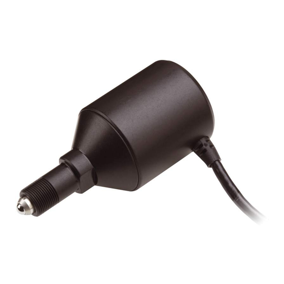
Getting Started Features Layout Velocity /Enable Knob Status LED CSA Compliance CE Compliance Parameter Reset Product Label Mounting Screws Cable securing (optional) tab mounting location (optional) Figure 4 Features Layout View Outside Dimensions Cable Lock Nut Figure 5 Outline Dimensions for NewStep Actuator. -
Page 17: Technical Specifications
Safety Precautions 2” 2” 6” Figure 6 Outline Dimensions for NewStep Controller. 2.5.1 Technical Specifications NSA12 Actuator Specifications Size (mm) Ø30x65 Travel (mm) Motor Stepper Open loop Motion sensitivity (µm) Repeatability (µm) Bi-directional repeatability ((µm) Max speed (mm/s) 2 (load dependent) Load capacity (N) 18N minimum Limit switches... -
Page 18: Table 2 Nsc100 Controller Specifications
Getting Started NSC100 Controller Specifications Output Power Continuous current 0.4A @ 15VDC Output Voltage Maximum effective output voltage at continuous power 15V @ 0.4A Input Power 15V ±5% Voltage Average Current @ continuous output rating 0.6A Peak Current @ continuous output rating 0.7A Table 2 NSC100 Controller Specifications... -
Page 19: Part Numbers
Safety Precautions 2.5.2 Part Numbers Part number Description NSA12 NewStep Actuator, 12 mm travel NSC100 NewStep Motion controller NSC-PS25 Universal power supply NSC-PSC2 Cable power supply to NSC100, 3 m length NSC-CB3 RS-485 Cable, 3 m length NSC-CB-485-232 RS-232 to RS-485 Converter NSC-JT RS-485 Junction box Table 4... - Page 20 Getting Started This page is intentionally left blank...
-
Page 21: Getting Started
Do not attempt to operate this equipment if there is evidence of shipping damage or you suspect the unit is damaged. Damaged equipment may present additional hazards to you. Contact Newport technical support for advice before attempting to plug in and operate damaged equipment. Parts List... -
Page 22: Choosing And Preparing Work Surface
Power cord/Power supply User’s Manual If you are missing any hardware or have questions about the hardware you have received, please contact Newport. Choosing and Preparing Work Surface The NewStep Actuator and Motion Controller may be placed on any reasonably firm table or bench during operation. -
Page 23: Operating Newstep
Operating NewStep CAUTION Before operating the NewStep Actuator and Motion Controller, please adhere to cautions in Section1. Overview 4.1.1 Operation Modes The NewStep Controller has two major Modes of Operation, REMOTE and LOCAL At power up, the Controller will default into REMOTE Mode. In REMOTE Mode the controller will respond to Computer Communications only and the Speed Adjustment Knob is disabled. -
Page 24: User Controls
Operating NewStep YELLOW GREEN Solid REMOTE Mode LOCAL Mode Error Condition REMOTE Mode, LOCAL Mode, Blinking Firmware Download In Motion In Motion Table 5 LED Status Table 4.1.2 User Controls In the LOCAL operations Mode, the controller responds to the Knob Velocity Adjustment commands. -
Page 25: Single Actuator, No Computer Interface (Minimal Configuration)
Operating NewStep Single Actuator, no Computer Interface 4.1.3 (minimal configuration... -
Page 26: Single Actuator With Computer Interface
Operating NewStep 4.1.4 Single Actuator with Computer Interface... -
Page 27: Two Actuators, No Computer Interface
Operating NewStep 4.1.5 Two Actuators, no Computer Interface... -
Page 28: Two Actuators With Computer Interface
Operating NewStep 4.1.6 Two Actuators with Computer Interface... -
Page 29: Multiple Actuators With Computer Interface
Operating NewStep 4.1.7 Multiple Actuators with Computer Interface... -
Page 30: Operation Modes
Operating NewStep Operation Modes The NewStep Controller has two major Modes of Operation, REMOTE and LOCAL At power up, the Controller will default into REMOTE Mode. In REMOTE Mode the controller will respond to Computer Communications only and the Speed Adjustment Knob is disabled. In the LOCAL mode, the Speed Adjustment Knob is enabled and the Computer Communications is disabled. - Page 31 Operating NewStep Also, the Knob is equipped with a push button that is used for changing the Operations Mode. By pressing this switch, the mode of operations changes between REMOTE (power up default) and LOCAL mode. This switch is also used for “Homing”...
- Page 32 Operating NewStep This page is intentionally left blank...
-
Page 33: Software
Software Overview The Newport NewStep Utility Program provides access to a majority of NewStep Controller’s functions and features, such as changing controller configuration, monitoring status, and issuing move/jog commands. Software Installation The Newport NewStep Utility Program (NewStep-Util) is designed to run on any commercially available Pentium™... -
Page 34: Using Newstep-Util
NewStep-Util provides control of the features available in the NewStep Controller. After installation is complete reboot your PC and execute NewStep- Util by double-clicking on the newly created icon in Newport / NewStep Controller folder. “Select Communication Port” window will open. -
Page 35: Figure 9 Initializing Controller Screen
Software After selecting the Port, if the Program finds any Uninitialized Controllers(Controller address equal to zero), the “Initialize Controller” window will open. The user then has to choose a valid controller address (a non-zero value) that has not been assigned to other controllers. NOTE When initializing, only one Uninitialized Controller may be connected to the network at a time. -
Page 36: Figure 10 Initializing Another Controller Dialog Box
Software Figure 10 Initializing another Controller dialog box. After all Controllers are initialized, “Scan Controller” window will open. Select the range of controller numbers to scan for. The maximum range is from 1 to 255. NOTE Note that the time taken to scan the bus is proportional to the maximum scan controller addresses selected. -
Page 37: Figure 12 Main Screen
Software Now, the main screen will become available. Position text box Figure 12 Main screen The top portion of the main screen shows position information for the selected controller. The position information can be shown in user defined units or micro- steps by clicking on the button next to the position text box. - Page 38 Software The main window has five tabs to choose from: Move, View All, Setup Status, and About. The Setup tab shows information specific to the selected controller. Axis Description is an arbitrary description that user can define. This is a convenient way for providing custom names to controllers.
-
Page 39: Figure 13 View All Tab Screen
Software The next tab is the View All tab. In this screen all the active Controllers on the RS485 network are shown. Figure 13 View all Tab Screen The Move tab enables the user to move the actuator. There are three ways to move the actuator. -
Page 40: Figure 14 Move Tab Screen
Software Figure 14 Move Tab Screen Cycle – NewStep Cycle Utility window opens up when the “Cycle” button is clicked. Here the user can specify any two absolute positions between which the actuator has to be moved. The dwell time between moves can be specified in milli-seconds. -
Page 41: Figure 15 Cycle Utility Screen
Software Figure 15 Cycle Utility Screen The Status tab enables the user to review hardware status of LEDs, limit switches, buttons, encoders, etc. Figure 16 Status screen... -
Page 42: Figure 17 Software And Hardware Information Screen
Software The About tab will show version of the Software Utility itself, and firmware version for the instrument connected currently. Figure 17 Software and Hardware Information Screen... -
Page 43: Newstep Controller Ascii Command Set
NewStep Controller ASCII Command Set Command Summary This document describes the supported two-letter ASCII commands that may be used to configure and operate the NewStep Controller, when in REMOTE mode (Yellow LED). Since multiple NewStep Controllers may be placed on the RS485 Bus, each controller will use a predetermined address (Controller Number) and by decoding the address field of the incoming messages, it can determine if the message is intended for it. -
Page 44: Table 7 Summary Of Commands Table
Command Set Reset Controller Number Negative Software Limit Save Memory Positive Software Limit Stop Motion Tell Error Tell Position Controller Status Velocity Firmware version Maximum Velocity Table 7 Summary Of Commands Table... - Page 45 Command Set set acceleration ♦ USAGE SYNTAX xxACnn or xxAC? PARAMETERS Description [ int ] Controller number [float ] Acceleration value Range 0 to 255 0 to the maximum programmed value in AU command or xxAC? to read current setting Units None Full Steps/second...
- Page 46 Command Set REL. set maximum acceleration and COMMANDS deceleration execute an absolute motion execute a relative motion set velocity EXAMPLE 21AC12.5 Set acceleration value to 12.5 for controller 21 Read the acceleration value 21AC? from controller 21...
- Page 47 Command Set set maximum acceleration ♦ USAGE SYNTAX xxAUnn or xxAU? PARAMETERS Description [ int ] Controller number [float ] Acceleration value Range 0 to 255 0 to 500 or xxAU? to read current setting Units None Full Steps/second Defaults missing: None out of range:...
- Page 48 Command Set set velocity EXAMPLE Set the maximum acceleration to 12.5 for 21AU12.5 controller 21 21AU? Read the maximum acceleration value from controller 21...
- Page 49 Command Set set backlash compensation ♦ USAGE SYNTAX xxBAnn or xxBA? PARAMETERS Description [ int ] Controller number Backlash [ int ] compensation value Range 0 to 255 0 to 512 Units None Micro-steps Defaults missing: None out of range: None error 38, Parameter missing:...
- Page 50 Command Set restore EEPROM content to default ♦ USAGE SYNTAX xxBZ PARAMETERS Description [ int ] Controller number Range None Units None Defaults missing: None out of range: None DESCRIPTION This commands restores the default values for all the nonvolatile settings. RETURNS REL.
- Page 51 Command Set start jog motion ♦ ♦ USAGE SYNTAX xxJAnn or xxJA? PARAMETERS Description [ int ] Controller number [ int ] Jog setting Range 0 to 255 0 to ±8 Units None None Defaults missing: none out of range: none missing: error 38, Parameter missing...
- Page 52 Command Set motor off ♦ ♦ USAGE SYNTAX xxMF PARAMETERS Description [ int ] Controller number [ int ] On/off Range 0 to 255 Units None Defaults missing: None out of range: None DESCRIPTION This command will turn the motor off. RETURNS This command has no return value.
- Page 53 Command Set motor on ♦ ♦ USAGE SYNTAX xxMO PARAMETERS Description [ int ] Controller number Range 0 to 255 Units None Defaults missing: None out of range: None DESCRIPTION This command will turn the motor ON. RETURNS This command has no return value. REL.
- Page 54 Command Set search for home ♦ USAGE SYNTAX xxOR PARAMETERS Description [ int ] Controller number Range 0 to 255 Units None Defaults missing: none out of range: none DESCRIPTION This command will start the process of homing the actuator to its negative hard limit.
- Page 55 Command Set move to absolute position ♦ USAGE SYNTAX xxPAnn or xxPA? PARAMETERS Description [ int ] Controller number [ int ] Position value Range 0 to 255 -60000 to 120000 Units Micro-steps Defaults Missing: None out of range: None missing: Error 37, Parameter Missing out of range:...
- Page 56 Command Set REL. set acceleration COMMANDS move to relative position stop motion set velocity EXAMPLE 12PA250 Move Actuator on controller 12 to absolute position 250 12PA? Read back the last commanded position...
- Page 57 Command Set get hardware status ♦ ♦ USAGE SYNTAX xxPH? PARAMETERS Description [ int ] Controller number Range 0 to 255 Units None Defaults missing: None out of range: None DESCRIPTION This command will return the value of the I/O ports of the processor in the Controller.
- Page 58 Command Set Bit Map Table O O O...
- Page 59 Command Set move by relative position ♦ USAGE SYNTAX xxPRnn or xxPR? PARAMETERS Description [ int ] Controller number [ int ] Position value Range 0 to 255 -60000 to 120000 Units Micro-steps Defaults Missing: None out of range: None missing: Error 37, Parameter Missing out of range:...
- Page 60 Command Set REL. set acceleration COMMANDS move to relative position stop motion set velocity EXAMPLE 12PR250 Move Actuator on controller12by+250 micro-steps 12PR? Read back the last commanded position...
- Page 61 Command Set reset the controller ♦ ♦ USAGE SYNTAX xxRS PARAMETERS Description [ int ] Controller Number Range 0 to 255 Units None Defaults missing: none out of range: none DESCRIPTION This command will reset the controller. This command will soft reset the processor in the controller.
- Page 62 Command Set set controller address ♦ ♦ USAGE SYNTAX xxSAnn PARAMETERS Description [ int ] Controller number, current [ int ] Controller number, new Range 0 to 255 0 to 255 Units None None Defaults missing: none out of range: none missing: error 38, Parameter missing...
- Page 63 Command Set set left travel limit ♦ USAGE SYNTAX xxSLnn or xxSL? PARAMETERS Description [ int ] Controller Number [ int ] Negative Software limit Range 0 to 255 -60000 to 1200000 Units None Micro-steps Defaults Missing: None out of range: None missing: Error 37, Parameter Missing...
- Page 64 Command Set save settings to non-volatile memory ♦ USAGE SYNTAX xxSM PARAMETERS Description [ int ] Controller Number Range 0 to 255 Units None Defaults missing: none out of range: none DESCRIPTION This command is used to save controller configuration settings from RAM to non-volatile EEROM memory.
- Page 65 Command Set set right travel limit ♦ USAGE SYNTAX xxSRnn or xxSR? PARAMETERS Description [ int ] Controller number [ int ] Positive software limit Range 0 to 255 -60000 to 1200000 Units None Micro-steps Defaults Missing: None out of range: None missing: Error 37, Parameter Missing...
- Page 66 Command Set Relative Move EXAMPLE 72SR-100 Sets the value of Positive software limit to –100 for controller 72 725SR? Reads back the value of the Positive Software Limit from controller 72...
- Page 67 Command Set stop motion ♦ ♦ USAGE SYNTAX xxST PARAMETERS Description [ int ] Controller number Range 0 to 255 Units None Defaults missing: none out of range: none DESCRIPTION This command stops a motion in progress using deceleration rate programmed with AC (set deceleration) command on the specified controller.
- Page 68 Command Set read error code ♦ ♦ USAGE SYNTAX xxTE? PARAMETERS Description [ int ] Controller number Range 0 to 255 Units None Defaults missing: None out of range: None DESCRIPTION This command is used to read the error code. RETURNS Error Code as described in table below REL.
- Page 69 Command Set Error Code Table Description Error Code No Errors Driver Fault (Open Load) Driver Fault (thermal shut down) Driver Fault (Short) Invalid Command Parameter Out of Range No Motor connected Brown Out Command Parameter Missing Positive Hardware Limit Detected Negative Hardware Limit Detected Positive Software Limit Detected Negative Software Limit Detected...
- Page 70 Command Set read position ♦ ♦ USAGE SYNTAX xxTP? PARAMETERS Description [ int ] Controller number Range 0 to 255 Units None Defaults missing: None out of range: None DESCRIPTION This command returns the position of the actuator in micro-steps. NOTE: The controller operates in an “open loop”...
- Page 71 Command Set controller status ♦ ♦ USAGE SYNTAX xxTS? PARAMETERS Description [ int ] Controller number Range 0 to 255 Units None Defaults missing: None out of range: None DESCRIPTION This command returns the controller status as following Motor ON & Motion NOT In progress Motor ON &...
- Page 72 Command Set set velocity ♦ USAGE SYNTAX xxVAnn or xxVA? PARAMETERS Description [ int ] Controller number [ float ] Velocity Range 0 to 255 0 to the maximum programmed value in VU command or xxVA? to read current setting Units None Full-steps/second...
- Page 73 Command Set read controller firmware version ♦ ♦ USAGE SYNTAX xxVE? PARAMETERS Description [ int ] Controller number Range 0 to 255 Units None Defaults missing: none out of range: none DESCRIPTION This command returns the firmware version with a “Major.Minor”...
- Page 74 Command Set set maximum velocity ♦ USAGE SYNTAX xxVUnn or xxVU? PARAMETERS Description [ int ] Controller number [ float ] Velocity Range 0 to 255 0 to the maximum programmed value in VU command or xxVA? to read current setting Units None Full-steps/second...
-
Page 75: Maintenance & Service
There are no user serviceable parts inside the NewStep Actuator and Motion Controller. Work performed by persons not authorized by Newport Corporation will void the warranty. Enclosure Cleaning The NewStep Actuator and Motion Controller should only be cleaned with a soapy water solution. - Page 76 Maintenance and Service Contact Newport to obtain information about factory service. Telephone contacts number(s) are provided on a Service Form. Please have the following information available: • Equipment model number (NSC100 NewStep Motion Controller or NSA12 Actuator) • Equipment Serial Number •...
-
Page 77: Service Form
Maintenance and Service Service Form Newport Corporation U.S.A. Office: 800-222-6440 FAX: 949/253-1479 Name ___________________Return Authorization _____________________ (Please obtain RA# prior to return of item) Company ________________________________________________________ (Please obtain RA # prior to return of item) Address ________________________________ Date ____________________ Country _______________________ Phone Number _____________________ P.O.
Need help?
Do you have a question about the NewStep NSA12 and is the answer not in the manual?
Questions and answers