Table of Contents
Advertisement
Advertisement
Table of Contents

Related Manuals for Newport ESP300 Series


Summary of Contents for Newport ESP300 Series
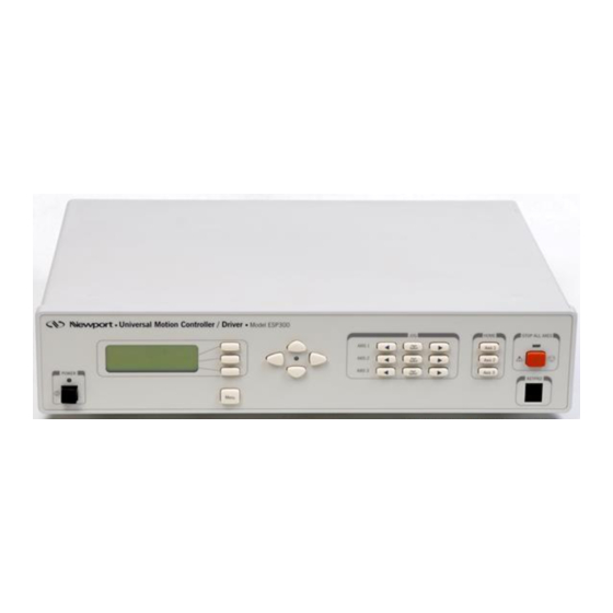
- Page 1 ESP300 Motion Controller/Driver User's Manual...
-
Page 2: Warranty
If found to be defective during the warranty period, the product will either be repaired or replaced at Newport's option. To exercise this warranty, write or call your local Newport office or representative, or contact Newport headquarters in Irvine, California. - Page 3 Access: Customer shall protect the Newport Programs and Related Materials as trade secrets of Newport, and shall devote its best efforts to ensure that all its personnel protect the Newport Programs as trade secrets of Newport Corporation. Customer shall not at any time disclose...
-
Page 4: Eu Declaration Of Conformity
ESP300 1999 EU Declaration of Conformity Preface... -
Page 5: Table Of Contents
Table of Contents Warranty ................ii Limitation of Warranty ............ii Copyright ................ii EU Declaration of Conformity........... iv Section 1 – Introduction ...........1-1 Scope ............... 1-1 Safety Considerations ........1-2 Conventions and Definitions......1-3 1.3.1 Definitions and Symbols ....1-3 1.3.2 Terminology........ - Page 6 Remote Interfaces..........3-4 3.2.1 RS-232C Interface......3-4 3.2.2 IEEE488 Interface......3-5 Software Utilities ..........3-6 Command Syntax ..........3-7 3.4.1 Summary of Command Syntax ..3-8 Command Summary ........3-9 3.5.1 Command List by Category ..... 3-10 3.5.2 Command List - Alphabetical ..3-14 Description of Commands ......
- Page 7 5.2.2 Error ........... 5-3 5.2.3 Accuracy ..........5-3 5.2.4 Local Accuracy ........5-4 5.2.5 Resolution .......... 5-6 5.2.6 Minimum Incremental Motion... 5-6 5.2.7 Repeatability ........5-7 5.2.8 Backlash (Hysteresis)......5-8 5.2.9 Pitch, Roll and Yaw ......5-9 5.2.10 Wobble ..........5-10 5.2.11 Load Capacity ........
- Page 8 Appendix A – Error Messages......... A-1 Appendix B – Trouble-Shooting/Maintenance ..B-1 Trouble-Shooting Guide .........B-2 Fuse Replacement ...........B-4 B.2.1 Replacing Fuses on the ESP300 Rear Power Line Panel .......B-4 Cleaning ............B-5 Appendix C – Connector Pin Assignments.... C-1 ESP300 Rear Panel .........C-1 C.1.1 GPIO Connector (37-Pin D-Sub) ..C-1 C.1.2...
- Page 9 Appendix H – Factory Service......... H-1 Service Form ..........H-2 List of Figures Figure No. Page Figure 1.1: ESP 300 Controller/Driver ..........1-6 Figure 1.2: ESP300 Front Panel with displays ......1-9 Figure 1.3: Rear Panel of the ESP300..........1-10 Figure 2.1: Menu Section..............2-2 Figure 2.2: Menu Item..............2-3 Figure 2.3: Motion from the Front Panel Displayed ......2-3 Figure 3.1: Command Syntax Diagram ..........3-7...
- Page 10 Figure 5.23: Slow Speed Home (Origin) Switch Search....5-21 Figure 5.24: High/Low-Speed Home (Origin) Switch Search ...5-21 Figure 5.25: Home (Origin) Search From Opposite Direction ...............5-22 Figure 5.26: Encoder Quadrature Output .........5-23 Figure 5.27: Optical Encoder Scale...........5-23 Figure 5.28: Optical Encoder Read Head .........5-24 Figure 5.29: Single-Channel Optical Encoder Scale and Read Head Assembly..........5-24 Figure 5.30: Two-Channel Optical Encoder Scale and...
- Page 11 List of Tables Table No. Page Table 3.5.1: Command List by Category........3-10 Table 3.5.2: Command List - Alphabetical........3-14 Table 4.1: Slave to a Different Stage Steps ........4-8 Table 4.2: Slave to a Trackball Steps ..........4-9 Table 4.3: Slave to a Joystick Steps..........4-9 Table 4.4: An Example of Closed Loop Stepper Motor Positioning Setup ..........
- Page 12 Command Index (Section 3) Command Description Page in section 3- abort motion ....................20 set acceleration...................21 set e-stop deceleration................23 set acceleration feed-forward gain .............25 set deceleration...................26 abort program.....................28 set maximum acceleration and deceleration ..........29 set backlash compensation.................30 assign DIO bits to execute stored programs ..........31 assign DIO bits to inhibit motion...............32 enable DIO bits to inhibit motion ..............33 assign DIO bits to notify motion status............34...
- Page 13 set group deceleration ................68 set group e-stop deceleration ..............70 group off.....................71 set group jerk....................72 move group along a line................73 create new group ..................75 group on .....................77 read group position ..................78 wait for group command buffer level ............79 stop group motion ..................80 set group velocity..................81 HW wait for group motion stop.................82 delete group....................84...
- Page 14 reset the controller..................123 set / get DIO port A, B bit status..............126 set master-slave jog velocity update interval ...........129 set master-slave jog velocity scaling coefficients........130 set left travel limit ..................131 save settings to non-volatile memory ............132 set axis displacement units...............133 set right travel limit..................134 define master-slave relationship ..............135 stop motion....................136...
-
Page 15: Section 1 - Introduction
Section 1 - Introduction Scope This manual provides descriptions and operating procedures for the integrated 3 axis ESP300 Controller/Driver (ESP = Enhanced System Performance). There are two configurations available: ESP300 - XXXXX1: 150W Power Supply Models ESP300 – XXXXX2: 400W Power Supply Models Safety considerations, conventions and definitions, and a system overview are provided in Section 1, Introduction. -
Page 16: Safety Considerations
To protect the equipment from damage and avoid hazardous situations, follow these recommendations: • Do not make modifications or parts substitutions. • Return equipment to Newport Corporation for service and repair. • Do not touch, directly or with other objects, live circuits inside the unit. -
Page 17: Conventions And Definitions
WARNING This product is equipped with a 3-wire grounding type plug. Any interruption of the grounding connection can create an electric shock hazard. If you are unable to insert the plug into your wall plug receptacle, contact an electrician to perform the necessary alterations to assure that the green (green-yellow) wire is attached to earth ground. - Page 18 WARNING Calls attention to a procedure, practice or condition which, if not correctly performed or adhered to, could result in injury or death. CAUTION Calls attention to a procedure, practice, or condition which, if not correctly performed or adhered to, could result in damage to property or equipment.
-
Page 19: Terminology
ESP is synonymous with a plug-and-play motion system. ESP – compatible – refers to Newport Corporation stage with its own firmware-based configuration parameters. Newport stages or other stages without this feature are referred to as being not ESP- compatible and must be uniquely configured by the user. -
Page 20: System Overview
System Overview The Enhanced System Performance (ESP) architecture consists of the ESP300 Controller/Driver and ESP-compatible stages. The ESP300 is an advanced stand-alone controller with integrated motor drivers. It can control and drive up to 3 axes of motion in any stepper and DC motor configuration. -
Page 21: Specifications
Trajectory type: • Trapezoidal velocity profile • S-curve velocity profile. Motion device compatibility: • Family of motorized Newport motion devices, using either stepper or DC motors • Custom motion devices (call for compatibility). DC motor control: • 18 bit DAC resolution •... -
Page 22: Descriptions Of Front Panel Versions
Optional display: • 80 character alpha-numeric LCD display • Displays position, status, utility menus and setup screens. Dimensions: • 3" (2U) H x 16.5" W x 12" D (75 x 412 x 300 mm) for ESP300- XXXXX1 Models • 3" (2U) H x 16.5" W x 13.5" D (75 x 412 x 342.9 mm) for ESP300-XXXXX2 Models Power requirements: •... -
Page 23: Rear Panel Description
FRONT PANEL DISPLAY A general view of the front panel is shown in (Figure 1.2). There are two distinct areas: a display/menu section and a motion/home section that allows simple manual motion sequence like JOG and HOMING. Home Buttons X-Y buttons Stop All Axis Display Menu... -
Page 24: Figure 1.3: Rear Panel Of The Esp300
+/GPIO CONNECTOR This is a 37-pin D-Sub connector used for general purpose, digital Input/Output signals. A variety of commands are available to control these ports. See Section 3, Remote Mode and Appendix C for Connector Pin Outs. Serial No. Label GPIO RS232-C Motor... -
Page 25: System Setup
Push in the POWER switch on the lower left side of the front panel. Shortly after the power is switched on, the ESP300 with front panel display will perform a start-up sequence as described below. • Momentarily display: "Newport ESP300" and the Firmware Version Section 2 – Modes of Operation... -
Page 26: Quick Start
• Momentarily show the stage type that is connected. Since there should be no stages connected at this point, the "NO STAGE" message is displayed for all axes. NOTE Any time you call for technical support, the firmware version is essential to trouble-shoot a problem. -
Page 27: Motor On
Users of the ESP300 with blank front panel can skip to Section 3, Remote Mode. 1.6.2 Motor On After the controller and the stages are connected as described, the motors can be powered on. Make sure that the motion devices are placed on a flat surface and their full travel is not obstructed. -
Page 28: First Jog
The display will indicate that a home routine is in progress with to the left of the axis number. NOTE The position value is reset at the home position. Only one axis can be homed at a time; i.e., even if multiple homing commands are issued, the prior axis has to finish homing before the second can start homing. - Page 29 This page is intentionally left blank. Section 2 – Modes of Operation 1-15...
-
Page 31: Section 2 - Modes Of Operation
Section 2 – Modes of Operation Overview of Operating Modes The ESP300 can be operated in two basic modes: • LOCAL mode • REMOTE mode 2.1.1 LOCAL Mode This mode is applicable only if your unit is equipped with the optional front panel display. -
Page 32: Operation In Local Mode
Operation in LOCAL Mode This section provides a detailed explanation of the LOCAL mode. Typical parameters that can be set are velocity, acceleration, PID values for DC motors, and many more. Please remember that all menu items can also be accessed with remote commands (See Section 3, Remote Mode). -
Page 33: Motion From The Front Panel
1. Press Menu to enter the menu listing. 2. Press the Down Arrow repeatedly until the cursor (diamond shaped) is aligned with the SET VELOCITY menu item. 3. Press the Right Arrow button once. Now, a sub-menu list becomes available. 4. - Page 34 Move in Negative Direction with low speed. This button can be programmed to cause motion in user definable increments or to move as long as it is pressed. See SET JOG MODE and SET VELOCITY menu items in Section 2.2.5. Move in Positive Direction with low speed.
-
Page 35: Detailed Description Of Menu Items
2.2.5 Detailed Description of Menu Items TOP OF MENU Note This menu item is only displayed if there is GET ERRORS an error in the queue. RESET POSITION RUN PROGRAMM SET VELOCITIES SET LO JOG VEL SET HIGH JOG VEL SET HOME VEL SET ACCEL/DECEL SET ACCELERATION... - Page 36 GET ERRORS This menu item allows the user to get the errors that are stored in the error queue. The error queue can store up to 10 errors. If the number of errors exceeds ten, the oldest errors are created. TE or TB Tell error or Tell buffer RUN PROGRAM...
- Page 37 SET HOME VEL Sets the velocity used during homing sequences. Refer to Section 1.6.3 for details on homing. Set home velocity SET ACCEL/DECEL This menu makes it possible to change acceleration and deceleration that are used with the jog and home search buttons. The following sub-menus are available: SET ACCELERATION Sets the acceleration that is used to accelerate to the desired velocity...
- Page 38 SET HOME MODE This menu allows the user to choose between two homing modes. Please refer to Section 5.4.3 for a detailed description of homing. Please note that this menu only selects the homing method, but does not initiate a home search. Home searches are initiated by pressing the HOME button for the respective axis.
- Page 39 SET KP Sets the integral gain of the digital PID filter. Set proportional gain SET KI Sets the integral gain of the digital PID filter. Set integral gain SET KD Sets the derivative gain of the digital PID filter. Set derivative gain. SET IL Sets the limit for the integrated value due to the integral gain KI factor of the digital PID filter.
- Page 40 GET RS232 CONFIG This menu allows the user to retrieve the current RS232 configuration settings. SAVE PARAMETERS This menu allows the users to save all current settings (velocity, acceleration, etc.) to the ESP300 non-volatile memory. 2-10 Section 2 – Modes of Operation...
-
Page 41: Section 3 - Remote Mode
Section 3 – Remote Mode Programming Modes The ESP is a command driven system. In general commands are a series of two letter ASCII characters preceded by an axis number and followed by parameters specific to the command. To communicate with the ESP controller, a host terminal has to transfer ASCII character commands according to the respective communication protocol (See Section 3.2 for IEEE-488 or RS232 interfaces). - Page 42 Assuming that axis 1 and 2 are configured, Example 1 instructs the ESP controller to move axis 1 to absolute position +30 units, wait for it to stop, and then move axis 2 motor to relative –10 units. Note that a command prefix identifies the axis or group that should execute a command.
- Page 43 PROGRAM EXECUTION MODE The ESP controller also implements an internal program execution mode that enables the user to store up to 100 programs in a 64kB non- volatile memory. Even while executing stored programs, the ESP controller maintains open communication channels so that the host terminal can continue to direct the ESP to report any desired status, and even execute other motion commands.
-
Page 44: Remote Interfaces
Remote Interfaces In this manual, Remote Interface refers to the two communication interfaces that the controller can use to communicate with a computer or a terminal via commands in ASCII format. It is not called a Computer Interface since any device capable of sending ASCII characters can be interfaced with the controller. -
Page 45: Ieee488 Interface
3.2.2 IEEE-488 Interface HARDWARE CONFIGURATION A typical IEEE-488 setup consists of a controller (host terminal) and several devices connected to the bus. All devices are connected in parallel to the data lines, data management and synchronization lines. As a result of this type of connection, each device on the bus must have a unique address so that the controller can selectively communicate with it. -
Page 46: Software Utilities
1PR10; 1WS100; 2PR10; 3PR10; 3WS100; RQ In the above example, the SRQ line is asserted only after execution of the sequence preceding the RQ command is finished. SERIAL POLL When the IEEE-488 controller senses a service request on the bus, it creates an interrupt to the application program (if configured to do so). -
Page 47: Command Syntax
Command Syntax As mentioned previously, the ESP controller utilizes an ASCII command set and also outputs system status in ASCII format. Commands may be either upper or lower case characters. The diagram below illustrates the ESP controller command syntax. As indicated in this diagram, a valid command consists of three main fields. -
Page 48: Summary Of Command Syntax
3.4.1 Summary of Command Syntax COMMAND FORMAT The general format of a command is a two character mnemonic (AA). Both upper and lower case are accepted. Depending on the command, it could also have optional or required preceding (xx) and/or following (nn) parameters. -
Page 49: Command Summary
Command Summary The controller understands many commands. The following tables list all of them, sorted first by category and then alphabetically. The tables also show the operating modes in which each command can be used. The acronyms used in the tables have the following meaning: IMMediate mode Controller is idle and the commands will be executed... -
Page 50: Ab Abort Motion
TABLE 3.5.1 – Command List by Category In a PDF format you may click on a page number to automatically be connected to the corresponding Command Page GENERAL MODE SELECTION STATUS FUNCTIONS Cmd. Description Page ♦ ♦ Get target position Get working speed ♦... - Page 51 ♦ ♦ ♦ Torque reduction Set microstep factor ♦ ♦ ♦ ♦ Define tachometer constant ♦ ♦ Set motor voltage ♦ ♦ ♦ Set master-slave jog update interval Set slave axis jog velocity ♦ ♦ ♦ coefficients ♦ ♦ ♦ Set left limit ♦...
- Page 52 ♦ ♦ ♦ Set velocity Set base velocity for step motors ♦ ♦ ♦ ♦ ♦ ♦ Set maximum speed FLOW CONTROL & SEQUENCING Cmd. Description Page ♦ Define label ♦ ♦ Jump to label Generate service request ♦ ♦ ♦...
- Page 53 ♦ ♦ ♦ Set group E-stop deceleration Group motor power OFF ♦ ♦ ♦ ♦ ♦ ♦ Set group jerk ♦ ♦ ♦ Move group along a line ♦ ♦ Create new group Group motor power ON ♦ ♦ ♦ Get group position ♦...
- Page 54 TABLE 3.5.2 – Command List – Alphabetical In a PDF format you may click on a page number to automatically be connected to the corresponding Command Page Cmd. Description Page ♦ ♦ Abort Motion Set acceleration ♦ ♦ ♦ ♦ ♦...
-
Page 55: Table 3.5.2: Command List - Alphabetical
TABLE 3.5.2 – Command List – Alphabetical (Continued) In a PDF format you may click on a page number to automatically be connected to the corresponding Command Page Cmd. Description Page ♦ ♦ ♦ Set position display resolution Set full step resolution ♦... - Page 56 TABLE 3.5.2 – Command List – Alphabetical (Continued) In a PDF format you may click on a page number to automatically be connected to the corresponding Command Page Cmd. Description Page ♦ ♦ Search for home Move to absolute position ♦...
-
Page 57: Ac Set Acceleration
TABLE 3.5.2 – Command List – Alphabetical (Continued) In a PDF format you may click on a page number to automatically be connected to the corresponding Command Page Cmd. Description Page ♦ Wait for DIO bit low Set velocity ♦ ♦... - Page 58 NOTE Most of the commands take an axis number as a parameter (xx). For such commands, the valid range of axis number is from 1 to MAX AXES, where MAX AXES is dependant on the configuration of the ESP motion controller. Commands related to coordinated motion and contouring (group commands) take a group number as a parameter.
- Page 59 AA – (command mnemonic) (brief definition) (motor type) * (the diamonds mark which mode the command can be used in) ♦ IMM ♦ PGM ♦ MIP USAGE (modes of operation) SYNTAX xxAAnn (generic syntax format) PARAMETERS Description xx [ int ] (description of parameter) Nn [float] (description of parameter)
- Page 60 abort motion IMM PGM ♦ ♦ USAGE SYNTAX PARAMETERS None. DESCRIPTION This command should be used as an emergency stop. On reception of this command, the controller invokes emergency stop event processing for each axis as configured by ZE (e-stop event configuration) command. By default axes are configured to turn motor power OFF, however, individual axes can be configured to stop using emergency deceleration rate set by AE command and maintain motor power.
- Page 61 set acceleration IMM PGM ♦ ♦ ♦ USAGE SYNTAX xxACnn or xxAC? PARAMETERS Description xx [ int ] axis number nn [float] acceleration value Range 1 to MAX AXES 0 to the maximum programmed value in AU command or ? to read current setting Units none predefined units / second 2...
- Page 62 | controller returns a value of 10 units/s 2 | set acceleration to 9 units/s 2 2AC9 | set deceleration to 6 units/s 2 2AG6 | set axis # 2 maximum acceleration/deceleration to 15 units/s 2 2AU15 2AU? | read maximum allowed acceleration & deceleration of axis # 2 | controller returns a value of 15 units 3-22 Section 3 –...
-
Page 63: Ae Set E-Stop Deceleration
set e-stop deceleration IMM PGM ♦ ♦ ♦ USAGE SYNTAX xxAEnn or xxAE? PARAMETERS Description xx [ int ] axis number nn [float] e-stop deceleration value Range 1 to MAX AXES current normal deceleration value to 2e9 * encoder resolution or ? to read current setting Units none... - Page 64 set maximum acceleration and deceleration set deceleration set acceleration EXAMPLE 2AE? | read e-stop deceleration of axis # 2 | controller returns a value of 100 units/s 2 | set e-stop deceleration to 150 units/s 2 2AE150 3-24 Section 3 – Remote Mode...
-
Page 65: Af Set Acceleration Feed-Forward Gain
set acceleration feed-forward gain IMM PGM ♦ ♦ ♦ USAGE SYNTAX xxAFnn or xxAF? PARAMETERS Description xx [ int ] axis number nn [float] acceleration feed-forward gain factor Range 1 to MAX AXES 0 to 2e9, or ? to read current setting Units none none... - Page 66 set deceleration IMM PGM ♦ ♦ ♦ USAGE SYNTAX xxAGnn or xxAG? PARAMETERS Description xx [ int ] axis number nn [float] acceleration value Range 1 to MAX AXES to the maximum programmed value in AU command or ? to read current setting Units none predefined units / second 2...
- Page 67 EXAMPLE 2AU? | read maximum allowed acceleration/deceleration of axis # 2 | controller returns a value of 10 units/s 2 | set acceleration to 9 units/s 2 2AC9 | set deceleration to 6 units/s 2 2AG6 2AG? | read maximum current deceleration of axis # 2 | controller returns a value of 6 units/s 2 Section 3 –...
-
Page 68: Ap Abort Program
abort program IMM PGM ♦ ♦ ♦ USAGE SYNTAX PARAMETERS none DESCRIPTION This command is used to interrupt a motion program in execution. It will not stop a motion in progress. It will only stop the program after the current command line finished executing. - Page 69 set maximum acceleration and deceleration IMM PGM ♦ ♦ ♦ USAGE SYNTAX xxAUnn or xxAU? PARAMETERS Description xx [ int ] axis number nn [float] acceleration value Range 1 to MAX AXES 0 to 2e+9, or ? to read current setting Units none predefined units / second 2...
-
Page 70: Ba Set Backlash Compensation
set backlash compensation IMM PGM MIP ♦ ♦ ♦ USAGE SYNTAX xxBAnn or xxBA? PARAMETERS Description xx [ int ] axis number nn [ float ] backlash compensation value Range 1 to MAX AXES to distance equivalent to 10000 encoder counts Units none user units... -
Page 71: Bg Assign Dio Bits To Execute Stored Programs
assign DIO bits to execute stored programs ♦ ♦ USAGE SYNTAX xxBGnn or xxBG? PARAMETERS Description xx [ int ] bit number used to trigger stored program execution nn [ char ] name of stored program to be executed Range 0 to 15 None or ? to read current setting Units... - Page 72 assign DIO bits to inhibit motion ♦ ♦ ♦ USAGE SYNTAX xxBKnn1, nn2 or xxBK? PARAMETERS Description xx [ int ] axis number nn1 [ int ] bit number for inhibiting motion nn2 [ int ] bit level when axis motion is inhibited Range 1 to MAX AXES 0 to 15...
-
Page 73: Bk Assign Dio Bits To Inhibit Motion
enable DIO bits to inhibit motion ♦ ♦ ♦ USAGE SYNTAX xxBLnn or xxBL? PARAMETERS Description xx [ int ] axis number nn [ int ] disable or enable Range 1 to MAX AXES 0 = disable, and 1 = enable or ? to read current setting Units None Defaults... -
Page 74: Bm Assign Dio Bits To Notify Motion Status
assign DIO bits to notify motion status ♦ ♦ ♦ USAGE SYNTAX xxBMnn1, nn2 or xxBM? PARAMETERS Description xx [ int ] axis number nn1 [ int ] bit number for notifying motion status nn2 [ int ] bit level when axis is not moving Range 1 to MAX AXES 0 to 15... -
Page 75: Bn Enable Dio Bits To Notify Motion Status
enable DIO bits to notify motion status ♦ ♦ ♦ USAGE SYNTAX xxBNnn or xxBN? PARAMETERS Description xx [ int ] axis number nn [ int ] disable or enable Range 1 to MAX AXES 0 = disable, and 1 = enable or ? to read current setting Units None Defaults... -
Page 76: Bo Set Dio Port A, B Direction
set DIO port A, B direction IMM PGM MIP ♦ ♦ ♦ USAGE SYNTAX BOnn or BO? PARAMETERS Description nn [ int ] hardware limit configuration Range 0 to 03H (hexadecimal with leading zero(0)) on ESP100 and ESP300 or ? to read current setting Units None Defaults... - Page 77 REL. COMMANDS set/clear DIO bits EXAMPLE BO? | read DIO port direction configuration | controller returns a value of 0H (all ports are input) BO 1H | configure DIO port A as output SB 0FFH | set all port A DIO output HIGH Section 3 –...
- Page 78 assign DIO bits for jog mode ♦ ♦ ♦ USAGE SYNTAX xxBPnn1,nn2 or xxBP? PARAMETERS Description xx [ int ] axis number nn1 [ int ] bit number for jogging in negative direction nn2 [ int ] bit number for jogging in positive direction Range 1 to MAX AXES 0 to 15...
-
Page 79: Bp Assign Dio Bits For Jog Mode
enable DIO bits for jog mode IMM PGM MIP ♦ ♦ ♦ USAGE SYNTAX xxBQnn or BQ? PARAMETERS Description xx [ int ] axis number nn [ int ] disable or enable Range 1 to MAX AXES 0 = disable, and 1 = enable Units none Defaults... - Page 80 set closed loop update interval ♦ ♦ ♦ USAGE SYNTAX xxCLnn or xxCL? PARAMETERS Description xx { int ] axis number nn [ int ] closed loop update interval Range 0 to MAX AXES 0 to 60000 Units none milliseconds Defaults missing: error 37, AXIS NUMBER MISSING...
- Page 81 set linear compensation IMM PGM MIP ♦ ♦ ♦ USAGE SYNTAX xxCOnn or xxCO? PARAMETERS Description xx [ int ] axis number nn [ float ] linear compensation value Range 1 to MAX AXES 0 to 2e+9 Units none none Defaults missing: error 37, AXIS NUMBER MISSING out of range:...
-
Page 82: Cl Set Closed Loop Update Interval
set position deadband IMM PGM MIP ♦ ♦ ♦ USAGE SYNTAX xxDBnn or xxDB? PARAMETERS Description xx [ int ] axis number nn [ int ] deadband value Range 0 to MAX AXES to 2e9 Units none encoder counts Defaults missing: error 37, AXIS NUMBER MISSING out of range:... -
Page 83: Dc Setup Data Acquisition
setup data acquisition ♦ ♦ USAGE SYNTAX DCnn1,nn2,nn3,nn4,nn5,nn6 PARAMETERS Description nn1 [ int ] data acquisition mode nn2 [ int ] axis used to trigger data acquisition nn3 [ int ] data acquisition parameter 3 nn4 [ int ] data acquisition parameter 4 nn5 [ int ] data acquisition rate nn6 [ int ]... -
Page 84: Dd Get Data Acquisition Done Status
Position feedback channels collected none channel 1 channel 2 channel 1 & 2 channel 3 channel 1 & 3 channel 2 & 4 channel 1,2,3 PARAMETER nn5: The rate at which data is to be acquired is specified through this parameter. - Page 85 get data acquisition done status IMM PGM MIP ♦ ♦ USAGE SYNTAX PARAMETERS none DESCRIPTION This command returns the status of a data acquisition request. RETURNS aa, where: aa = 1 for True, 0 for False REL. COMMANDS setup data acquisition request get acquired data data acquisition status, returns # of samples collected enable / disable data acquisition...
-
Page 86: De Enable/Disable Data Acquisition
enable/disable data acquisition IMM PGM MIP ♦ ♦ USAGE SYNTAX DEnn PARAMETERS Description nn [ int ] True | False Range 1 for True, 0 for False DESCRIPTION This command is used to enable / disable the data acquisition request. Note: This command cannot be issued when: An axis is being homed (refer ASCII command, OR). - Page 87 get data acquisition sample count IMM PGM MIP ♦ ♦ USAGE SYNTAX PARAMETERS none DESCRIPTION This command returns the number of a data acquisition collected to the point of this request. RETURNS aa, where: aa = number of samples REL. COMMANDS setup data acquisition request get acquired data data acquisition done status...
-
Page 88: Dg Get Acquisition Data
get acquisition data IMM PGM MIP ♦ ♦ USAGE SYNTAX PARAMETERS None DESCRIPTION This command is used to retrieve data acquired from a data acquisition request. RETURNS This command returns byte wide binary data. Each four bytes represents one DSP 32 bit word. The number of bytes returned depends on the setup request. (See DC command). -
Page 89: Dh Define Home
define home IMM PGM MIP ♦ ♦ USAGE SYNTAX xxDHnn PARAMETERS Description xx [ int ] axis number nn [float] - position value Range 1 to MAX AXES 0 to ± 2e+9 Units none predefined units Defaults missing: error 37, AXIS NUMBER MISSING out of range: error 9, AXIS NUMBER OUT OF RANGE missing:... -
Page 90: Dl Define Label
define label IMM PGM ♦ USAGE SYNTAX xxDL PARAMETERS Description xx [ int ] label number Range 1 to 100 Units none Default missing: error 38, COMMAND PARAMETER MISSING out of range: error xx2, PARAMETER OUT OF RANGE DESCRIPTION This command defines a label inside a program. In combination with JL (jump to label) command, they offer significant program flow control. -
Page 91: Do Set Dac Offset
set dac offset IMM PGM MIP ♦ ♦ ♦ USAGE SYNTAX xxDOnn or xxDO? PARAMETERS Description xx [ int ] DAC channel number nn [ float ] DAC offset value Range 1 to MAX AXES -10.0 to 10.0 or ? to read the current setting Units None Volts... -
Page 92: Dp Read Desired Position
read desired position IMM PGM ♦ ♦ ♦ USAGE SYNTAX xxDP? PARAMETERS Description xx [ int ] axis number Range 1 to MAX AXES Units none Defaults missing: error 37, AXIS NUMBER MISSING out of range: error 9, AXIS NUMBER OUT OF RANGE DESCRIPTION This command is used to read the desired position. - Page 93 read desired velocity IMM PGM MIP ♦ ♦ USAGE SYNTAX xxDV PARAMETERS Description xx [ int ] axis number Range 1 to MAX AXES Units none Defaults missing: error 37, AXIS NUMBER MISSING out of range: error 9, AXIS NUMBER OUT OF RANGE DESCRIPTION This command is used to read the desired velocity of an axis.
-
Page 94: Eo Automatic Execution On Power On
automatic execution on power on IMM PGM MIP ♦ ♦ USAGE SYNTAX xxEOnn or xxEO? PARAMETERS Description xx [ int ] - program number nn [ int ] - number of times of execution Range - 1 to 100 - 1 to 2e9 Units - none - none... -
Page 95: Ep Enter Program Mode
enter program mode IMM PGM ♦ USAGE SYNTAX xxEP PARAMETERS Description xx [ int ] program number Range 1 to 100 Units none Defaults missing: error 38, COMMAND PARAMETER MISSING out of range: error 7, PARAMETER OUT OF RANGE DESCRIPTION This command sets the controller in programming mode. -
Page 96: Es Define Event Action Command String
define event action command string IMM PGM MIP ♦ ♦ USAGE SYNTAX ESnn or ES? PARAMETERS Description nn [ string ] - ASCII command string (184 characters max) Range Limited to existing (non-query) command support or ? to read the current setting Units None Defaults... - Page 97 EXAMPLE DC3,1,3,5,0,1 | Param. #1: Acquire analog data on an external trigger | Param. #2: No consequence for this data acquisition mode | Param. #3: Acquire analog channels 1 & 2 (3 = (11) | Param. #4: Acquire feedback channels 1 & 3 (5 = (101) | Param.
-
Page 98: Ex Execute A Program
execute a program IMM PGM MIPO ♦ ♦ USAGE SYNTAX xxEXnn PARAMETERS Description xx [ int ] program number nn [ int ] number of times to execute the program Range 1 to 100 1 to 2147385345 Units none none Defaults missing: error 38, COMMAND PARAMETER MISSING... - Page 99 set maximum following error threshold IMM PGM ♦ ♦ ♦ USAGE SYNTAX xxFEnn or xxFE? PARAMETERS Description xx [ int ] axis number nn [float] - maximum allowed following error Range 1 to MAX AXES 0 to(2e9 * encoder resolution), or ? to read current setting Units none...
- Page 100 set position display resolution IMM PGM MIP ♦ ♦ ♦ USAGE SYNTAX xxFPnn or xxFP? PARAMETERS Description xx [ int ] axis number nn [ int ] display resolution Range 1 to MAX AXES 0 to 7 or ? to read present setting Units none none...
- Page 101 PARAMETER OUT OF RANGE DESCRIPTION This command is used to set the encoder full step resolution for a Newport Unidrive compatible programmable driver with step motor axis. RETURNS If “?” sign takes the place of nn value, this command reports current setting.
- Page 102 set master-slave reduction ratio IMM PGM MIP ♦ ♦ ♦ USAGE SYNTAX xxGRnn or xxGR? PARAMETERS Description xx [ int ] axis number nn [ float ] reduction ratio Range 1 to MAX AXES ±1,000,000 Units none none Defaults missing: error 37, AXIS NUMBER MISSING out of range: error 9, AXIS NUMBER OUT OF RANGE...
- Page 103 set group acceleration IMM PGM MIP ♦ ♦ ♦ USAGE SYNTAX xxHAnn or xxHA? PARAMETERS Description xx [ int ] group number nn [ float ] vector acceleration value Range 1 to MAX GROUPS 0 to minimum of the maximum acceleration values of all axes assigned to this group.
- Page 104 EXAMPLE 1HN1,2 | create a new group (#1) with physical axes 1 and 2 1AU? | query maximum acceleration of axis #1 | controller returns a value of 50 units/second 2AU? | query maximum acceleration of axis #2 | controller returns a value of 60 units/second | set vectorial acceleration of group #1 to 50 units/second 1HA50 | query vectorial acceleration of group #1...
- Page 105 read list of groups assigned IMM PGM MIP ♦ ♦ USAGE SYNTAX PARAMETERS None DESCRIPTION This command is used to read the group numbers that have already been created or assigned. RETURNS This command reports the current setting. If no groups have been created, controller returns error number 15, GROUP NUMBER NOT ASSIGNED.
- Page 106 move group along an arc IMM PGM MIP ♦ ♦ ♦ USAGE SYNTAX xxHCnn , nn , nn or xxHC? PARAMETERS Description xx [ int ] group number [ float ] - first coordinate of arc center [ float ] - second coordinate of arc center [ float ] - arc sweep angle...
- Page 107 RETURNS If “?” sign takes the place of nn values, this command reports the commanded center position of arc and sweep angle. REL. COMMANDS create a new group set vectorial velocity for a group set vectorial acceleration for a group set vectorial deceleration for a group enable a group disable a group...
- Page 108 set group deceleration IMM PGM MIP ♦ ♦ ♦ USAGE SYNTAX xxHDnn or xxHD? PARAMETERS Description xx [ int ] group number nn [ float ] vector deceleration value Range 1 to MAX GROUPS 0 to minimum of the maximum deceleration values of all axes assigned to this group.
- Page 109 EXAMPLE 1HN1,2 | create a new group (#1) with physical axes 1 and 2 1AU? | query maximum deceleration of axis #1 | controller returns a value of 50 units/second 2AU? | query maximum deceleration of axis #2 | controller returns a value of 60 units/second 1HD50 | set vectorial deceleration of group #1 to 50 units/second 1HD?
- Page 110 set group e-stop deceleration IMM PGM MIP ♦ ♦ ♦ USAGE SYNTAX xxHEnn or xxHE? PARAMETERS Description xx [ int ] group number nn [ float ] vector e-stop deceleration value Range 1 to MAX GROUPS maximum of deceleration values assigned to all axes in the group to 2e9 * encoder resolution.
- Page 111 group off IMM PGM MIP ♦ ♦ ♦ USAGE SYNTAX xxHF or xxHF? PARAMETERS Description xx [ int ] group number Range 1 to MAX GROUPS Units none Defaults missing: error 13, GROUP NUMBER MISSING out of range: error 14, GROUP NUMBER OUT OF RANGE not assigned: error 15, GROUP NUMBER NOT ASSIGNED floating point:...
- Page 112 set group jerk IMM PGM MIP ♦ ♦ ♦ USAGE SYNTAX xxHJnn or xxHJ? PARAMETERS Description xx [ int ] group number nn [ float ] vector jerk value Range 1 to MAX GROUPS 0 to 2e9 Units none predefined units / second Defaults missing: error 13, GROUP NUMBER MISSING...
- Page 113 move group along a line IMM PGM MIP ♦ ♦ ♦ USAGE SYNTAX xxHLnn , nn , …nn or xxHL? PARAMETERS Description xx [ int ] group number [ float ] - target position of first axis in a group [ float ] - target position of second axis in a group [ float ] -...
- Page 114 REL. COMMANDS create a new group set vectorial velocity for a group set vectorial acceleration for a group set vectorial deceleration for a group enable a group disable a group move a group of axes to desired position along an arc. EXAMPLE 1HN1,2 | create a new group (#1) with physical axes 1 and 2...
- Page 115 create new group IMM PGM MIP ♦ ♦ USAGE SYNTAX xxHNnn , nn , …nn or xxHN? PARAMETERS Description xx [ int ] group number [ int ] physical axis number to be assigned as first axis in this group [ int ] physical axis number to be assigned as second axis in this group...
- Page 116 attempts to assign an axis under such circumstances. Refer HX command to delete a group. • An axis cannot be assigned more than once in a group. The controller returns error 19, GROUP AXIS DUPLICATED, if one attempts to assign an axis more than once to a group.
- Page 117 group on IMM PGM MIP ♦ ♦ ♦ USAGE SYNTAX xxHO or xxHO? PARAMETERS Description xx [ int ] group number Range 1 to MAX GROUPS Units none Defaults missing: error 13, GROUP NUMBER MISSING out of range: error 14, GROUP NUMBER OUT OF RANGE not assigned: error 15, GROUP NUMBER NOT ASSIGNED floating point:...
- Page 118 read group position ♦ ♦ USAGE SYNTAX xxHP PARAMETERS Description xx [ int ] group number Range 1 to MAX GROUPS Units none Defaults missing: error 13, GROUP NUMBER MISSING out of range: error 14, GROUP NUMBER OUT OF RANGE not assigned: error 15, GROUP NUMBER NOT ASSIGNED floating point:...
- Page 119 wait for group command buffer level ♦ ♦ ♦ USAGE SYNTAX xxHQnn or xxHQ? PARAMETERS Description xx [ int ] group number nn [ float ] level in group via point buffer Range 1 to MAX GROUPS to 10 (default for maximum targets in via point buffer) Units none milliseconds...
- Page 120 stop group motion IMM PGM MIP ♦ ♦ ♦ USAGE SYNTAX xxHS or xxHS? PARAMETERS Description xx [ int ] group number Range 1 to MAX GROUPS Units none Defaults missing: error 13, GROUP NUMBER MISSING out of range: error 14, GROUP NUMBER OUT OF RANGE not assigned: error 15, GROUP NUMBER NOT ASSIGNED floating point:...
- Page 121 set group velocity IMM PGM MIP ♦ ♦ ♦ USAGE SYNTAX xxHVnn or xxHV? PARAMETERS Description xx [ int ] group number nn [ float ] vector velocity value Range 1 to MAX GROUPS 0 to minimum of the maximum velocity values of all axes assigned to this group.
- Page 122 wait for group motion stop IMM PGM MIP ♦ ♦ ♦ USAGE SYNTAX xxHWnn PARAMETERS Description xx [ int ] group number nn [ float ] delay after group motion is complete Range 1 to MAX GROUPS 0 to 60000 Units none milliseconds...
- Page 123 | group to reach target position, wait an additional 500 ms, and | then move group #2 to a target position = 30, 20 units (axis #3 | = 30 units and axis #4 = 20 units) Section 3 – Remote Mode 3-83...
- Page 124 delete group IMM PGM MIP ♦ ♦ ♦ USAGE SYNTAX xxHX PARAMETERS Description xx [ int ] group number Range 1 to MAX GROUPS Units none Defaults missing: error 13, GROUP NUMBER MISSING out of range: error 14, GROUP NUMBER OUT OF RANGE not assigned: error 15, GROUP NUMBER NOT ASSIGNED DESCRIPTION...
- Page 125 read group size IMM PGM MIP ♦ ♦ ♦ USAGE SYNTAX xxHZ PARAMETERS Description xx [ int ] group number Range 1 to MAX GROUPS Units none Defaults missing: error 13, GROUP NUMBER MISSING out of range: error 14, GROUP NUMBER OUT OF RANGE not assigned: error 15, GROUP NUMBER NOT ASSIGNED DESCRIPTION...
- Page 126 2, RS-232 COMMUNICATION TIME-OUT DESCRIPTION This command is used to read and write (up to 16 character custom ID) Newport ESP compatible positioner (stage) model and serial number. Note: An important information needed when asking for help with the motion control system or when reporting a problem is the stage model and serial number.
- Page 127 set jog high speed IMM PGM MIP ♦ ♦ ♦ USAGE SYNTAX xxJHnn or xxJH? PARAMETERS Description xx [ int ] axis number nn [ float ] high speed value Range 1 to MAX AXES 0 to maximum value allowed by VU command or ? to read present setting Units none...
- Page 128 set jerk rate IMM PGM ♦ ♦ ♦ USAGE SYNTAX xxJKnn or xxJK? PARAMETERS Description xx [ int ] axis number nn [float] jerk value Range 1 to MAX AXES 0 to 2e9 Units none preset units / second or ? to read current setting Defaults missing: error 37, AXIS NUMBER MISSING...
- Page 129 jump to label IMM PGM ♦ ♦ USAGE SYNTAX xxJLnn PARAMETERS Description xx [ int ] - label number nn [ int ] - loop count Range - 1 to 100 - 1 to 65535 Units - none - none Default missing: error 38, COMMAND PARAMETER MISSING...
- Page 130 set jog low speed IMM PGM MIP ♦ ♦ ♦ USAGE SYNTAX xxJWnn or xxJW? PARAMETERS Description xx [ int ] axis number nn [ float ] low speed value Range 1 to MAX AXES 0 to maximum value allowed by VU command or ? to read present setting Units none...
- Page 131 set derivative gain IMM PGM ♦ ♦ ♦ USAGE SYNTAX xxKDnn or xxKD? PARAMETERS Description xx [ int ] axis number nn [float] derivative gain factor Kd Range 1 to MAX AXES 0 to 2e9, or ? to read current setting Units none none...
- Page 132 set integral gain ♦ ♦ ♦ USAGE SYNTAX xxKInn or xxKI? PARAMETERS Description xx [ int ] axis number nn [float] integral gain factor Ki Range 1 to MAX AXES 0 to 2e9, or ? to read current setting Units none Defaults missing:...
- Page 133 set proportional gain IMM PGM ♦ ♦ ♦ USAGE SYNTAX xxKPnn or xxKP? PARAMETERS Description xx [ int ] axis number nn [float] - proportional gain factor Kp Range 1 to MAX AXES 0 to 2e9, or ? to read current setting Units none none...
- Page 134 set saturation level of integral factor IMM PGM ♦ ♦ ♦ USAGE SYNTAX xxKSnn or xxKS? PARAMETERS Description xx [ int ] axis number nn [float] - saturation level of integrator KS Range 1 to MAX AXES 0 to 2e9, or ? to read current setting Units none none...
- Page 135 list program IMM PGM ♦ ♦ USAGE SYNTAX xxLP PARAMETERS Description xx [ int ] program number Range 1 to 100 Units none Defaults missing: error 38, COMMAND PARAMETER MISSING out of range: error 7, PARAMETER OUT OF RANGE DESCRIPTION This command reads a specified program from non-volatile memory and sends it to the selected communication port (RS232 or IEEE488).
- Page 136 read motion done status ♦ ♦ USAGE SYNTAX xxMD? PARAMETERS Description xx [ int ] axis number Range 1 to MAX AXES Units none Defaults missing: error 37, AXIS NUMBER MISSING out of range: error 9, AXIS NUMBER OUT OF RANGE DESCRIPTION This command is used to read the motion status for the specified axis n.
- Page 137 motor off IMM PGM MIP ♦ ♦ ♦ USAGE SYNTAX xxMF or xxMF? PARAMETERS Description xx [ int ] axis number Range 1 to MAX AXES Units none Defaults missing: error 37, AXIS NUMBER MISSING out of range: error 9, AXIS NUMBER OUT OF RANGE DESCRIPTION This command turns power OFF of the specified motor (axis).
-
Page 138: St Stop Motion
motor on ♦ ♦ ♦ USAGE SYNTAX xxMO or xxMO? PARAMETERS Description xx [ int ] axis number Range to MAX AXES Units none Defaults missing: error 37, AXIS NUMBER MISSING out of range: error 9, AXIS NUMBER OUT OF RANGE DESCRIPTION This command turns power ON of the specified motor (axis). - Page 139 move to hardware travel limit IMM PGM MIP ♦ ♦ USAGE SYNTAX xxMTnn or xxMT? PARAMETERS Description xx [ int ] axis number nn [ char ] direction of motion Range 1 to MAX AXES + for positive direction or − for negative direction Units none none...
- Page 140 move indefinitely IMM PGM ♦ ♦ ♦ USAGE SYNTAX xxMVnn or xxMV? PARAMETERS Description xx [ int ] - axis number nn [ char ] - direction of motion Range - 1 to MAX AXES - + for positive direction or − for negative direction Units - none - none...
- Page 141 REL. COMMANDS move to absolute position move to relative position stop motion move done status EXAMPLE 3MV+ | move axis #3 indefinitely in positive direction 3MV? | query status of move | controller returns 0 meaning, motion is in progress | stop axis #3 motion 3MV−...
- Page 142 move to nearest index ♦ ♦ USAGE SYNTAX xxMZnn or xxMZ? PARAMETERS Description xx [ int ] axis number nn [ char ] direction of motion Range 1 to MAX AXES + for positive direction or − for negative direction Units none none...
- Page 143 set home search high speed ♦ ♦ ♦ USAGE SYNTAX xxOHnn or xxOH? PARAMETERS Description xx [ int ] axis number nn [ float ] high speed value Range 1 to MAX AXES 0 to maximum value allowed by VU command or ? to read present setting Units none...
- Page 144 set home search low speed ♦ ♦ ♦ USAGE SYNTAX xxOLnn or xxOL? PARAMETERS Description xx [ int ] axis number nn [ float ] low speed value Range 1 to MAX AXES 0 to maximum value allowed by VU command or ? to read present setting Units none...
- Page 145 set home search mode ♦ ♦ ♦ USAGE SYNTAX PARAMETERS Description xx [ int ] axis number nn [ int ] home search mode Range 1 to MAX AXES 0 to 6 Units none none Defaults missing: error 37, AXIS NUMBER MISSING out of range: error 9, AXIS NUMBER OUT OF RANGE missing:...
- Page 146 search for home IMM PGM MIP ♦ ♦ USAGE SYNTAX xxORnn PARAMETERS Description xx [ int ] axis number nn [ int ] home mode Range 0 to MAX AXES 0 to 6 where: 0 = Find +0 Position Count 1 = Find Home and Index Signals 2 = Find Home Signal 3 = Find Positive Limit Signal...
- Page 147 Note: This command should be executed once every time the controller power is turned ON or the controller performs a complete system reset. There is no need to issue this command in any other case since the controller always keeps track of position, even when the motor power is OFF.
- Page 148 move to absolute position IMM PGM ♦ ♦ ♦ USAGE SYNTAX xxPAnn or xxPA? PARAMETERS Description xx [ int ] axis number nn [float] - absolute position destination Range 1 to MAX AXES any position within the travel limits and within ±2e9 * encoder resolution.
- Page 149 get hardware status IMM PGM MIP ♦ ♦ USAGE SYNTAX PARAMETERS None DESCRIPTION This command is used to get general hardware status for all axes. This routine allows user to observe the various digital input signals as they appear to the controller. ARDWARE TATUS EGISTER...
- Page 150 axis 1 amplifier fault input low axis 1 amplifier fault input high axis 2 amplifier fault input low axis 2 amplifier fault input high axis 3 amplifier fault input low axis 3 amplifier fault input high reserved reserved reserved reserved reserved reserved reserved...
- Page 151 reserved reserved reserved reserved axis 1 index signal low axis 1 index signal high axis 2 index signal low axis 2 index signal high axis 3 index signal low axis 3 index signal high reserved reserved reserved reserved reserved reserved reserved reserved reserved...
- Page 152 move to relative position IMM PGM ♦ ♦ ♦ USAGE SYNTAX xxPRnn PARAMETERS Description xx [ int ] axis number nn [float] - relative motion increment Range 1 to MAX AXES any value that will not cause exceeding the software limits and within 2e9 * encoder resolution.
- Page 153 Unidrive: error xx23, UNIDRIVE NOT DETECTED DESCRIPTION This command is used to update Newport programmable driver (i.e., Unidrive) settings into working registers. Note: This command should not be issued during motion since the motor power is automatically turned OFF.
- Page 154 PARAMETER OUT OF RANGE DESCRIPTION This command is used to set the gear constant for a Newport Unidrive compatible programmable driver for DC servo axis. This command should be used in conjunction with QT (tachometer gain) command.
- Page 155 PARAMETER OUT OF RA DESCRIPTION This command is used to set the maximum motor current output for a Newport Unidrive compatible programmable driver axis. This command must to be followed by the QD update driver command to take affect.
- Page 156 set motor type IMM PGM ♦ ♦ USAGE SYNTAX xxQMnn or xxQM? PARAMETERS Description xx [ int ] axis number nn [ int ] motor type Range 1 to MAX AXES 0 to 4 where 0 = motor type undefined (default) 1 = DC servo motor (single analog channel) 2 = step motor (digital control)* 3 = commutated step motor (analog control)
- Page 157 quit program mode IMM PGM ♦ USAGE SYNTAX PARAMETERS None DESCRIPTION This command quits the controller from programming mode. All the commands following this one will be executed immediately. RETURNS none REL. COMMANDS execute stored program abort stored program execution erase program EXAMPLE | clear program 3 from memory, if any...
- Page 158 reduce motor torque ♦ ♦ ♦ USAGE SYNTAX xxQRnn1,nn2 or xxQR? PARAMETERS Description xx [ int ] axis number nn1 [ int ] delay period nn2 [float ] - motor current reduction percentage Range 1 to MAX AXES 0 to 60000 0 to 100 Units none...
- Page 159 PARAMETER OUT OF RANGE DESCRIPTION This command is used to set the microstep factor for a Newport Unidrive compatible programmable driver with step motor axis. This command must be followed by the QD update driver command to take affect.
- Page 160 PARAMETER OUT OF RANGE DESCRIPTION This command is used to set the DC motor tachometer gain for a Newport Unidrive compatible programmable driver axis. This command should be used in conjunction with QG (gear constant) command.
- Page 161 PARAMETER OUT OF RANGE DESCRIPTION This command is used to set the average motor voltage output for a Newport Unidrive compatible programmable driver axis. This command must to be followed by the QD update driver command to take affect.
- Page 162 generate service request (SRQ) IMM PGM MIP ♦ ♦ ♦ USAGE SYNTAX RQnn PARAMETERS Description nn [ int ] interrupt number Range 0 to 31 Units none Defaults missing: out of range: error 7, PARAMETER OUT OF RANGE DESCRIPTION This command generates an interrupt service request to the host computer. The parameter nn is used to identify the RQ command what generated the interrupt.
- Page 163 reset the controller ♦ ♦ USAGE SYNTAX PARAMETERS None DESCRIPTION This command is used to perform a hardware reset of the controller. It performs the following preliminary tasks before resetting the controller: Stop all the axes that are in motion. The deceleration value specified using the command AG is used to stop the axes.
- Page 164 JPWDT1 JP11 For ESP6000 and ESP7000 motion controllers P5 (RS232) For ESP100 and ESP300 motion controllers RETURNS None REL. COMMANDS None EXAMPLE | Reset the controller 3-124 Section 3 – Remote Mode...
- Page 165 set device address IMM PGM ♦ ♦ ♦ USAGE SYNTAX SAnn or SA? PARAMETERS Description nn [ int ] address number Range 1 to 30 Units none Defaults missing: error 38, COMMAND PARAMETER MISSING out of range: error 7, PARAMETER OUT OF RANGE DESCRIPTION This command is used to set and report the device (i.e., ESP controller) address for use with IEEE-488 or USB communications (if equipped).
- Page 166 set / get DIO port A, B bit status IMM PGM MIP ♦ ♦ ♦ USAGE SYNTAX SBnn or SB? PARAMETERS Description nn [ int ] hardware limit configuration Range 0 to 0FFFFFFH (hexadecimal with leading zero(0) ) or ? to read current setting Units None Defaults...
- Page 167 port A bit-5 at logic level 0 (LOW) port A bit-5 at logic level 1 (HIGH) port A bit-6 at logic level 0 (LOW) port A bit-6 at logic level 1 (HIGH) port A bit-7 at logic level 0 (LOW) port A bit-7 at logic level 1 (HIGH) * default setting RETURNS...
- Page 168 set home preset position IMM PGM MIP ♦ ♦ ♦ USAGE SYNTAX xxSHnn or xxSH? PARAMETERS Description xx [ int ] axis number nn [ float ] - home preset position Range 1 to MAX AXES any position within the travel limits Units none defined motion units...
- Page 169 set master-slave jog velocity update interval IMM PGM MIP ♦ ♦ ♦ USAGE SYNTAX SInn or SI? PARAMETERS Description nn [ int ] jog velocity update interval Range 1 to 1000 Units milliseconds Defaults missing: error 38, COMMAND PARAMETER MISSING out of range: error 7, PARAMETER OUT OF RANGE DESCRIPTION...
- Page 170 set master-slave jog velocity scaling coefficients IMM PGM MIP ♦ ♦ ♦ USAGE SYNTAX SKnn1, nn2 or SK? PARAMETERS Description [ float ] - jog velocity scaling coefficients Range none Units none Defaults missing: error 38, COMMAND PARAMETER MISSING DESCRIPTION This command sets the jog velocity scaling coefficients for slave axis.
- Page 171 set left travel limit ♦ ♦ ♦ USAGE SYNTAX xxSLnn or xxSL? PARAMETERS Description xx [ int ] axis number nn [float] left (negative) software limit Range 1 to MAX AXES -2e9 ∗ encoder resolution to 0 Units none predefined motion units Defaults missing: error 37, AXIS NUMBER MISSING...
- Page 172 save settings to non-volatile memory IMM PGM ♦ ♦ USAGE SYNTAX PARAMETERS none DESCRIPTION This command is used to save system and axis configuration settings from RAM to non-volatile flash memory. It should be used after modifying system and/or axis parameters and settings to assure that the new data will not be lost when the controller is powered off.
-
Page 173: Su Set Encoder Resolution
set axis displacement units IMM PGM ♦ ♦ USAGE SYNTAX xxSNnn or xxSN? PARAMETERS Description xx [ int ] axis number nn [ int ] displacement units Range 1 to MAX AXES 0 to 10 where 0 = encoder count 6 = micro-inches 1 = motor step 7 = degree... - Page 174 set right travel limit IMM PGM ♦ ♦ USAGE SYNTAX xxSRnn or xxSR? PARAMETERS Description xx [ int ] axis number nn [float] - right (positive) software limit Range 1 to MAX AXES +2e9 ∗ encoder resolution to 0 Units none defined motion units Defaults...
- Page 175 define master-slave relationship IMM PGM MIP ♦ ♦ USAGE SYNTAX xxSSnn or xxSS? PARAMETERS Description xx [ int ] axis number to be defined as a slave nn [ int ] axis number to be defined as a master Range 1 to MAX AXES 1 to MAX AXES Units...
- Page 176 stop motion IMM PGM ♦ ♦ ♦ USAGE SYNTAX xxST PARAMETERS Description xx [ int ] axis number Range 1 to MAX AXES Units none Defaults out of range: error 9, AXIS NUMBER OUT OF RANGE DESCRIPTION This command stops a motion in progress using deceleration rate programmed with AG (set deceleration) command on the specified axes.
- Page 177 set encoder resolution IMM PGM ♦ ♦ USAGE SYNTAX xxSUnn or xxSU? PARAMETERS Description xx [ int ] axis number nn [float] encoder resolution Range 1 to MAX AXES 2e-9 to 2e+9 in user defined units or ? to read present setting Units none none...
-
Page 178: Tb Read Error Message
read error message IMM PGM ♦ ♦ USAGE SYNTAX PARAMETERS questions mark (?) Defaults DESCRIPTION This command is used to read the error code, timestamp, and the associated message. The error code is one numerical value up to three(3) digits long. (see Appendix for complete listing) In general, non-axis specific errors numbers range from 1-99. -
Page 179: Te Read Error Code
read error code IMM PGM ♦ ♦ USAGE SYNTAX PARAMETERS questions mark (?) Defaults timeout: error 2, RS-232 COMMUNICATION TIME-OUT DESCRIPTION This command is used to read the error code. The error code is one numerical value up to three digits long. (see Appendix for complete listing) In general, non-axis specific errors numbers range from 1-99. -
Page 180: Tj Set Trajectory Mode
set trajectory mode IMM PGM ♦ ♦ USAGE SYNTAX xxTJnn or xxTJ? PARAMETERS Description xx [ int ] axis number nn [ int ] home mode Range 1 to MAX AXES 1 to 6 where 1 = trapezoidal mode 2 = s-curve mode 3 = jog mode 4 = slave to master’s desired position (trajectory) 5 = slave to master’s actual position (feedback) -
Page 181: Tp Read Actual Position
read actual position IMM PGM ♦ ♦ USAGE SYNTAX xxTP PARAMETERS Description xx [ int ] axis number Range 1 to MAX AXES Units none Defaults missing: error 37, AXIS NUMBER MISSING out of range: error 9, AXIS NUMBER OUT OF RANGE DESCRIPTION This command is used to read the actual position. -
Page 182: Ts Read Controller Status
read controller status IMM PGM MIP ♦ ♦ USAGE SYNTAX PARAMETERS None DESCRIPTION This command is used to read the controller status byte. The byte returned is in the form of an ASCII character. The value of each bit in the status byte can be deduced after converting the ASCII character into a binary value. -
Page 183: Tv Read Actual Velocity
read actual velocity IMM PGM MIP ♦ ♦ USAGE SYNTAX xxTV PARAMETERS Description xx [ int ] axis number Range 1 to MAX AXES Units none Defaults missing: error 37, AXIS NUMBER MISSING out of range: error 9, AXIS NUMBER OUT OF RANGE DESCRIPTION This command is used to read the actual velocity of an axis. -
Page 184: Tx Read Controller Activity
read controller activity IMM PGM MIP ♦ ♦ USAGE SYNTAX PARAMETERS None DESCRIPTION This command is used to read the controller activity register. The byte returned is in the form of an ASCII character. The value of each bit in the status byte can be deduced after converting the ASCII character into a binary value. -
Page 185: Uf Update Servo Filter
update servo filter IMM PGM ♦ ♦ ♦ USAGE SYNTAX PARAMETERS None. DESCRIPTION This command is used to make active the latest entered PID parameters. Any new value for Kp, Ki, Kd and maximum following error are not being used in the PID loop calculation until UF command is received. -
Page 186: Uh Wait For Dio Bit High
wait for DIO bit high IMM PGM ♦ USAGE SYNTAX XxUH PARAMETERS Description xx [ int ] DIO bid number Range 0 to 15 Units none Defaults missing: error 38, COMMAND PARAMETER MISSING out of range: error 7, PARAMETER OUT OF RANGE DESCRIPTION This command causes a program to wait until a selected I/O input bit becomes high. -
Page 187: Ul Wait For Dio Bit Low
wait for DIO bit low IMM PGM ♦ USAGE SYNTAX XxUL PARAMETERS Description xx [ int ] DIO bid number Range 0 to 15 Units none Defaults missing: error 38, COMMAND PARAMETER MISSING out of range: error 7, PARAMETER OUT OF RANGE DESCRIPTION This command causes a program to wait until a selected I/O input bit becomes low. -
Page 188: Va Set Velocity
set velocity IMM PGM ♦ ♦ ♦ USAGE SYNTAX xxVAnn or xxVA? PARAMETERS Description xx [ int ] axis number nn [float] velocity value Range 1 to MAX AXES 0 to maximum value allowed by VU command or ? to read current setting Units none preset units / second... -
Page 189: Vb Set Base Velocity For Step Motors
set base velocity for step motors IMM PGM ♦ ♦ ♦ USAGE SYNTAX xxVBnn or xxVB? PARAMETERS Description xx [ int ] axis number nn [float] - base velocity value Range 1 to MAX AXES 0 to maximum value allowed by VU command or ? to read current setting Units none... -
Page 190: Ve Read Controller Firmware Version
read controller firmware version IMM PGM ♦ ♦ USAGE SYNTAX VE ? PARAMETERS none Defaults timeout: error 2, RS-232 COMMUNICATION TIME-OUT DESCRIPTION This command is used to read the controller type and version. Note: Important information needed when asking for technical support for the motion control system or when reporting a problem is the controller version. -
Page 191: Vf Set Velocity Feed-Forward Gain
set velocity feed-forward gain IMM PGM ♦ ♦ ♦ USAGE SYNTAX xxVFnn or xxVF? PARAMETERS Description xx [ int ] axis number nn [float] velocity feed-forward gain factor Vf Range 1 to MAX AXES 0 to 2e9, or ? to read current setting Units none none... -
Page 192: Vu Set Maximum Velocity
set maximum velocity IMM PGM ♦ ♦ ♦ USAGE SYNTAX xxVUnn or xxVU? PARAMETERS Description xx [ int ] axis number nn [float] velocity value Range to MAX AXES 0 to 2e+9, or ? to read current setting Units none predefined units / second Defaults missing:... -
Page 193: Wp Wait For Position
wait for position IMM PGM MIP ♦ ♦ ♦ USAGE SYNTAX xxWPnn PARAMETERS Description xx [ int ] axis number nn [ float ] position value Range 1 to MAX AXES starting position to destination of axis number xx Units none predefined units Defaults... - Page 194 wait for motion stop IMM PGM ♦ ♦ ♦ USAGE SYNTAX xxWSnn PARAMETERS Description xx [ int ] axis number nn [ int ] delay after motion is complete Range 0 to MAX AXES 0 to 60000 Units none milliseconds Defaults missing: error 37, AXIS NUMBER MISSING...
- Page 195 wait IMM PGM ♦ ♦ ♦ USAGE SYNTAX WTnn PARAMETERS Description nn [ int ] wait time (delay) Range 0 to 60000 Units milliseconds Defaults missing: error 37, AXIS NUMBER MISSING out of range: error 9, AXIS NUMBER OUT OF RANGE missing: error 38, COMMAND PARAMETER MISSING out of range:...
-
Page 196: Xm Read Available Memory
read available memory IMM PGM MIP ♦ ♦ USAGE SYNTAX PARAMETERS None DESCRIPTION This command reports the amount of unused program memory. The controller has 61440 bytes of non-volatile memory available for permanently storing programs. This command reports the amount not used. Note: Available memory space is updated only after the stored program memory is purged using XX command. -
Page 197: Erase Program
erase program IMM PGM MIP ♦ ♦ USAGE SYNTAX xxXX PARAMETERS Description xx [ int ] program number Range 1 to 100 Units none Defaults missing: error 38, COMMAND PARAMETER MISSING out of range: error 7, PARAMETER OUT OF RANGE DESCRIPTION This command makes the program xx loaded in controller’s non-volatile memory unavailable to user. -
Page 198: Za Set Amplifier I/O Configuration
set amplifier I/O configuration IMM PGM ♦ ♦ USAGE SYNTAX xxZAnn or xxZA? PARAMETERS Description xx [ int ] axis number nn [ int ] amplifier I/O configuration Range 1 to MAX AXES 0 to 0FFFFH (hexadecimal with leading zero(0) ) or ? to read current setting Units none... - Page 199 VALUE DEFINITION disable amplifier fault input checking enable amplifier fault input checking do not disable motor on amplifier fault event disable motor on amplifier fault event do not abort motion on amplifier fault event abort motion on amplifier fault event reserved reserved reserved...
- Page 200 EXAMPLE 2ZA? | read amplifier I/O configuration of axis # 2 123H | controller returns a value of 123H for axis #2 | 123H = (0001 0010 0011)Binary | Bits 0, 1, 5, 8 = 1. All other bits = 0 2ZA 125H | set amplifier I/O configuration to 125H for axis #2 | 125H = (0001 0010 0101)Binary...
-
Page 201: Zb Set Feedback Configuration
set feedback configuration IMM PGM ♦ ♦ USAGE SYNTAX xxZBnn or xxZB? PARAMETERS Description xx [ int ] axis number nn [ int ] feedback configuration Range 1 to MAX AXES 0 to 0FFFFH (hexadecimal with leading zero(0) ) or ? to read current setting Units none none... - Page 202 BIT# VALUE DEFINITION disable feedback error checking enable feedback error checking do not disable motor on feedback error event disable motor on feedback error event do not abort motion on feedback error event abort motion on feedback error event reserve reserve reserve reserve...
- Page 203 set e-stop configuration IMM PGM ♦ ♦ USAGE SYNTAX xxZEnn or xxZE? PARAMETERS Description xx [ int ] axis number nn [ int ] e-stop configuration Range 1 to MAX AXES 0 to 0FFFFH (hexadecimal with leading zero(0) ) or ? to read current setting Units none none...
- Page 204 BIT# VALUE DEFINITION disable E-stop checking enable E-stop checking do not disable motor power on E-stop event disable motor power on E-stop event do not abort motion on E-stop event abort motion on E-stop event reserved reserved reserved reserved reserved reserved reserved reserved...
- Page 205 set following error configuration IMM PGM ♦ ♦ USAGE SYNTAX xxZFnn or xxZF? PARAMETERS Description xx [ int ] axis number nn [ int ] following error configuration Range 1 to MAX AXES 0 to 0FFFFH (hexadecimal with leading zero(0) ) or ? to read current setting Units none...
-
Page 206: Ze Set E-Stop Configuration
BIT# VALUE DEFINITION disable motor following error checking enable motor following error checking do not disable motor power on following error event disable motor power on following error event do not abort motion on following error event abort motion on following error event reserved reserved reserved... -
Page 207: Zh Set Hardware Limit Configuration
set hardware limit configuration IMM PGM ♦ ♦ USAGE SYNTAX xxZHnn or xxZH? PARAMETERS Description xx [ int ] axis number nn [ int ] hardware limit configuration Range 1 to MAX AXES 0 to 0FFFFH (hexadecimal with leading zero(0) ) or ? to read current setting Units none... - Page 208 VALUE DEFINITION disable hardware travel limit error checking enable hardware travel limit error checking do not disable motor on hardware travel limit event disable motor on hardware travel limit event do not abort motion on hardware travel limit event abort motion on hardware travel limit event reserved reserved reserved...
- Page 209 set software limit configuration IMM PGM ♦ ♦ USAGE SYNTAX xxZSnn or xxZS? PARAMETERS Description xx [ int ] axis number nn [ int ] hardware limit configuration Range 1 to MAX AXES 0 to 0FFFFH (hexadecimal with leading zero(0) ) or ? to read current setting Units none...
- Page 210 VALUE DEFINITION disable software travel limit error checking enable software travel limit error checking do not disable motor on software travel limit event disable motor on software travel limit event do not abort motion on software travel limit event abort motion on software travel limit event reserved reserved reserved...
- Page 211 get ESP system configuration IMM PGM MIP ♦ ♦ USAGE SYNTAX PARAMETERS None DESCRIPTION This command is used to get the present ESP system stage/driver configuration. After each system reset or initialization the ESP motion controller detects the presence of Universal drivers and ESP-compatible stages connected. BIT# VALUE DEFINITION...
-
Page 212: Zs Set Software Limit Configuration
set software limit configuration set system configuration EXAMPLE | read ESP system configuration 150015H | controller returns a value of 150015H 3-172 Section 3 – Remote Mode... - Page 213 set system configuration IMM PGM MIP ♦ ♦ USAGE SYNTAX ZZnn or ZZ? PARAMETERS Description nn [ int ] - system configuration Range 0 to 0FFFFH (hexadecimal with leading zero(0) ) or ? to read current setting Units none Defaults missing: error 38, COMMAND PARAMETER MISSING out of range:...
- Page 214 DEFINITION disable 100-pin interlock error checking enable 100-pin interlock error checking do not disable all axes on 100-pin interlock error event disable all axes on 100-pin interlock error event reserved reserved reserved reserved configure interlock fault as active low configure interlock fault as active high reserved reserved reserved...
-
Page 215: Grouping
Section 4 – Advanced Capabilities Grouping 4.1.1 Introduction – Advanced Capabilities Coordinated motion of multiple axes is required to produce a desired contour in a multi-dimensional space. For instance, if we want to move from one point to another along a line or along a circle, or a combination of both line and circle, we require coordinated motion of multiple axes. -
Page 216: Defining Group Parameters
If a group has only one axis assigned to it, a linear motion of the group is similar to moving that axis from one point to another. Circular motion of a group with only one axis cannot be made. If a group has more than two axes assigned to it, circular motion of the group is made using the first two axes in the group. -
Page 217: Making Linear Move
4.1.3.1 Making Linear Move Once a group has been defined and all group parameters have been specified, the ASCII command HL is used to move the group from an initial position to a final position along the line. The current position of axes is the initial position of linear move. -
Page 218: Making Contours
− − − θ − θ θ axis π θ θ − axis θ θ θ axis θ θ θ axis θ ∗ cos( axis θ ∗ cos( axis where: and Y represent initial position of the group. -
Page 219: Figure 4.1: A Contour With Multiple Circular Moves
These move segments can be sequenced in any order. Arcs can be followed by arcs or lines, and lines by arcs or other lines as shown in the following figures. Since there is no pre-processing of move segments involved in making a contour, the user must ensure that there is no change in tangential velocity at the transition from one move to another. -
Page 220: Figure 4.3: Block Diagram Of Via Point Data Handling By Command Processor
This mechanism will block the portal through which the commands were issued until all the commands issued have been executed. It is, therefore, recommended that the user take advantage of ASCII command, HQ which tells the number of commands that can be put in the "via point"... -
Page 221: Miscellaneous Commands
Begin Is there a move Process current move Move In Progress? command pending in the command via point buffer? Process new move command Current move Do not bring the current move target reached? to a halt when target is reached Pull out the top most move Bring the current move to a halt command in the via point... -
Page 222: Table 4.1: Slave To A Different Stage Steps
The first two ways may be used when absolute or relative move commands can be issued to the master. This is the situation when both master and slave axes are driven by valid motor types. The third way may be used when move commands cannot be issued to the master. This is the situation when the slave axis is driven by a valid motor type, but the master, such as trackball or joystick, is not. -
Page 223: Table 4.2: Slave To A Trackball Steps
Steps Move Action by Move Command Command 1. Define master-slave 2SS4 Axis #2 is the slave of axis #4 relationship 2. Define slave axis jog. Update slave axis jog velocity 2S1100 Velocity update interval every 100 milliseconds 3. Define slave axis scaling 2SK0.5, 0 Specify scaling coefficients coefficients... -
Page 224: Feature Implementation
Due to such physical attributes, a significant position error can be generated when systems are moved from one position to another by stepper motors without any closed loop control mechanism. This error can be further accentuated by micro-stepping and non-collection of encoders (necessary to have closed loop control) and motors. -
Page 225: Table 4.4: An Example Of Closed Loop Stepper Motor
Start closed loop stepper positioning Desired Is actual motion position within desired Motion done completed? deadband? Start closed loop Make desired update interval correction timer Wait for timer to reset Exit closed loop stepper positioning Figure 4.5: Block Diagram of Closed Loop Stepper Motor Positioning The following steps (See Table 4.4 ) may be followed to setup the closed loop stepper motor positioning. -
Page 226: Table 4.5: Closed Loop Stepper Positioning Commands
Command Description Set feedback configuration. Specify deadband value. Specify closed loop update interval. Table 4.5: Closed Loop Stepper Positioning Commands Synchronize Motion to External and Internal Events 4.4.1 Introduction – Synchronize Motion Certain applications require the use of inputs from an external source to command the motion controller to perform certain tasks. - Page 227 The direction of the DIO port bit belongs to must then be set to "input" in order for the controller to detect the external event. Once these preliminaries are completed, the controller will execute the user specified stored program whenever it detects a change in the state – HIGH to LOW logic level –...
-
Page 228: Using Dio To Inhibit Motion
4.4.3 Using DIO to Inhibit Motion ESP series of motion controllers can inhibit the motion of any axis in response to external events. In order to accomplish this task, users must define the DIO bit to be employed to inhibit the motion of a desired axis and the logic state in which that bit should be in order to inhibit motion. -
Page 229: Table 4.6: Commands To Synchronize Motion To External Events
Example 3: 2BM9,1 | Use DIO bit #9 to indicate motion status of axis #2. This DIO | bit will be set to HIGH when axis #2 is not in motion 2BN1 | Enable notification of motion status using DIO for axis #2 BO 06H | 06H = (0110)Binary | Set DIO port A, to input and ports B, C to output... - Page 230 4-16 Section 4 – Advanced Capabilities...
-
Page 231: Motion Systems
Section 5 – Motion Control Tutorial Motion Systems A schematic of a typical motion control system is shown in Figure 5.1. Figure 5.1: Typical Motion Control Systems Its major components are: Controller An electronic device that receives motion commands from an operator directly or via a computer, verifies the real motion device position and generates the necessary control signals. -
Page 232: Specification Definitions
Driver An electronic device that converts the control signals to the correct format and power needed to drive the motors. Motion Device An electro-mechanical device that can move a load with the necessary specifications. Cables Needed to interconnect the other motion control components. If the user is like most motion control users, they started by selecting a motion device that matches certain specifications needed for an application. -
Page 233: Following Error
For this reason, all factory measurements are made using a number of high precision interferometers, most of them connected to a computerized test station. • To avoid unnecessary confusion and to more easily understand and troubleshoot a problem, special attention must be paid to avoid bundling discrete errors in one general term. -
Page 234: Local Accuracy
The Accuracy is a static measure of a point-to-point positioning error. Starting from a reference point, the user should command the controller to move a certain distance. When the motion is completed, the user should measure the actual distance traveled with an external precision-measuring device. -
Page 235: Figure 5.3A: High Accuracy For Small Motions
Error max. error Position Figure 5.3a: High Accuracy for Small Motions Error max. error Position Figure 5.3b: Low Accuracy for Small Motions Both error plots from Figure 5.3a and Figure 5.3b have a similar maximum Error. But, if the user compares the maximum Error for small distances, the system in Figure 5.3b shows significantly larger values. -
Page 236: Resolution
5.2.5 Resolution Resolution is the smallest motion that the controller attempts to make. For all DC motor and most all standard stepper motor driven stages supported by the ESP3000, this is also the resolution of the encoder. Keeping in mind that the servo loop is a digital loop, the Resolution can be also viewed as the smallest position increment that the controller can handle. -
Page 237: Repeatability
Assume that the user has a motion device with a 1 µm resolution. If every time the user commands a 1 µm motion the measured error is never greater than 2%, the user will probably be very satisfied and declare that the Minimum Incremental Motion is better than 1 µm. If, on the other hand, the measured motion is sometimes as small as 0.1 µm (a 90% error), the user could not say that 1 µm is a reliable motion step. -
Page 238: Figure 5.7: Hysteresis Plot
5.2.8 Backlash and Hysteresis Hysteresis and Backlash contribute to error caused by approaching a point from a different direction. Backlash The maximum magnitude of an input that produces no measurable output upon reversing direction. It can be a result of insufficient axial preloads or poor meshing between drivetrain components, i.e., gear teeth in a gear-coupled drivetrain. -
Page 239: Pitch, Roll And Yaw
Real position ideal plot real plot Trajectory (ideal position) Figure 5.8: Real vs. Ideal Position To justify a little more why we call this Hysteresis, lets do the same graph in a different format ( Figure 5.8 ). Plotting the real versus the ideal position will give the user a familiar hysteresis shape. -
Page 240: Wobble
5.2.10 Wobble This parameter applies only to rotary stages. It represents the deviation of the axis of rotation during motion. A simple form of Wobble is a constant one, where the rotating axis generates a circle ( Figure 5.11 ). Figure 5.11: Wobble Generates a Circle A real rotary stage may have a more complex Wobble, where the axis of rotation follows a complicated trajectory. -
Page 241: Maximum Velocity
5.2.12 Maximum Velocity The Maximum Velocity that could be used in a motion control system is determined by both motion device and driver. Usually it represents a lower value than the motor or driver is capable of. In most cases, including the ESP300, the default Maximum Velocity should be increased. -
Page 242: Velocity Regulation
In the case of a DC motor, adjusting the PID parameters to get a softer response will reduce the velocity ripple but care must be taken not to negatively affect other desirable motion characteristics. 5.2.14 Velocity Regulation In some applications, for example scanning, it is important for the velocity to be very constant. -
Page 243: Combined Parameters
require it. The driver, motor, motion device and load undergo maximum stress during high acceleration. 5.2.16 Combined Parameters Very often a user looks at an application and concludes that they need a certain overall accuracy. This usually means that the user is combining a number of individual terms (error parameters) into a single one. -
Page 244: Pid Servo Loops
Command Trajectory Servo Driver Motor Interpreter Generator Controller Motion Controller Encoder Figure 5.13: Servo Loop 5.3.1 PID Servo Loops The PID term comes from the proportional, integral and derivative gain factors that are at the basis of the control loop calculation. The common equation given for it is: •... -
Page 245: Figure 5.14: P Loop
• Higher velocities need higher motor voltages and thus higher following errors. • At stop, small errors cannot be corrected if they don't generate enough voltage for the motor to overcome friction and stiction. • Increasing the K gain reduces the necessary following error but too much of it will generate instabilities and oscillations. -
Page 246: Feed-Forward Loops
PID Loop The third term of the PID Loop is the derivative term. It is defined as the difference between the following error of the current servo cycle and of the previous one. If the following error does not change, the derivative term is zero. -
Page 247: Figure 5.17: Trapezoidal Velocity Profile
Because the signal is derived from the velocity profile and it is being sent directly to motor driver, the procedure is called velocity feed- forward. Of course, this looks like an open loop, and it is ( Figure 5.18 ). But, adding this signal to the closed loop has the effect of significantly reducing the "work"... -
Page 248: Motion Profiles
If such a driver is used with a velocity feed-forward algorithm, by properly tuning the K parameter, the feed-forward signal could perform an excellent job, leaving very little for the PID loop to do. Servo Controller Trajectory Generator Motor ∫ Driver Kvff Tachometer... -
Page 249: Figure 5.20: Trapezoidal Motion Profile
Desired Velocity Time Figure 5.20: Trapezoidal Motion Profile The position and acceleration profiles relative to the velocity are shown in ( Figure 5.21 ). Position Desired Velocity Time Acceleration Figure 5.21: Position and Acceleration Profiles Besides the destination, the acceleration and the velocity of the motion (the constant portion of it) can be set by the user before every move command. -
Page 250: Home Search
5.4.3 Home Search Home search is a specific motion routine that is useful for most types of applications. Its goal is to find a specific point in travel relative to the mounting base of the motion device very accurately and repeatable. -
Page 251: Figure 5.22: Home (Origin) Switch And Encoder Index Pulse
origin switch encoder index pulse Figure 5.22: Home (Origin) Switch and Encoder Index Pulse The task of the home search routine is to identify one unique index pulse as the absolute position reference. This is done by the first finding the home switch transition and then the very first index pulse ( Figure 5.23 ). -
Page 252: Encoders
Motion segment B is performed at high speed, with the pre- programmed home search speed. When the home switch transition is encountered, the motion device stops (with an overshoot), reverses direction and looks for it again, this time with half the velocity (segment C). -
Page 253: Figure 5.26: Encoder Quadrature Output
Figure 5.26: Encoder Quadrature Output The output has two signals, commonly known as channel A and channel B. Some encoders have analog outputs (sine – cosine signals) but the digital type are more widely used. Both channels have a 50% duty cycle and are out of phase by 90°. -
Page 254: Figure 5.28: Optical Encoder Read Head
The encoder read head has three major components: a light source, a mask and a detector ( Figure 5.28 ). The mask is a small scale-like piece, having identically spaced transparent and opaque lines. Figure 5.28: Optical Encoder Read Head Combining the scale with the read head, when one moves relative to another, the light will pass through where the transparent areas line up or blocked when they do not line up ( Figure 5.29 ). -
Page 255: Figure 5.30: Two-Channel Optical Encoder Scale And Read Head Assembly
There are two basic types of encoders: linear and rotary. The linear encoders, also called linear scales, are used to measure linear motion directly. This means that the physical resolution of the scale will be the actual positioning resolution. This is their main drawback since technological limitations prevent them from having better resolutions than a few microns. -
Page 256: Motors
Motors There are many different types of electrical motors, each one being best suitable for certain kind of applications. The ESP300 supports two of the most popular types: stepper motors and DC motors. Other technologies like interferometry or halography can be used but they are significantly more expansive and need more space. -
Page 257: Figure 5.32: Four-Phase Stepper Motor
The stepper motor advantages to a new stable position by means of several stator phases that have the teeth slightly offset from each other. To illustrate this, ( Figure 5.32) shows a stepper motor with four phases and, to make it easier to follow, it is drawn in a linear fashion (as a linear stepper motor). -
Page 258: Figure 5.34: Energizing Two Phases Simultaneously
Figure 5.34: Energizing Two Phases Simultaneously Both phases will pull equally on the motor will move the rotor only half of the full step. If the phases are always energized two at a time, the motor still makes full steps. But, if the user alternates one and two phases being activated simultaneously, the result is that the motor will move only half a step at a time. -
Page 259: Figure 5.37: Timing Diagram, Continuous Motion (Ideal)
The conclusion is that, varying the ratio between the currents of the two phases, the user can position the rotor anywhere between the two full step locations. To do so, the user needs to drive the motor with analog signals, similar to ( Figure 5.37 ). Figure 5.37: Timing Diagram, Continuous Motion (Ideal) But a stepper motor should be stepping. -
Page 260: Figure 5.39: Single Phase Energization
If external forces try to move the rotor ( Figure 5.40 ), the magnetic flux will fight back. The more teeth misalignment exists, the larger the generated torque. Figure 5.39: Single Phase Energization Figure 5.40: External Force Applied If the misalignment keeps increasing, at some point, the torque peaks and then starts diminishing again such that, when the stator is exactly between the rotor teeth, the torque becomes zero again ( Figure 5.41 ). -
Page 261: Stepper Motor Types
This torque diagram is accurate even when the motor is driven with half-, mini-, or micro-steps. The maximum torque is still one full step away from the stable (desired) position. 5.6.1.1 Stepper Motor Types To simplify the explanation, the examples above are based on a variable reluctance stepper motor. -
Page 262: Dc Motors
• Large velocity ripples, especially at low speeds, causing noise and possible resonances • Load torque must be significantly lower than the motor holding torque to prevent stalling and missing steps • Limited high speed 5.6.2 DC Motors A DC motor is similar to a permanent magnet stepper motor with an added internal phase commutator ( Figure 5.43 ). -
Page 263: Drivers
Disadvantages Some of the DC motor's disadvantages are: • Requires a position feedback encoder and servo loop controller • Requires servo loop tuning • Commutator may wear out in time • Not suitable for high vacuum application due to the commutator arcing •... -
Page 264: Figure 5.44: Simple Stepper Motor Driver
Figure 5.44: Simple Stepper Motor Driver When the pulse rate is flat, the current does not have time to reach the desired value before it is turned off and the total torque generated is only a fraction of the nominal one ( Figure 5.46 ). How fast the current reaches its nominal value depends on three factor: the winding's inductance, resistance and the voltage applied to it. -
Page 265: Unipolar-Bipolar Drivers
If, for instance, a stepper motor requiring only 3V to reach the nominal current is connected momentarily to 30V, it will reach the same current on only 1/10 of the time ( Figure 5.47 ). nominal current Phase ON Figure 5.47: Motor Pulse with High Voltage Chopper Once the desired current value is reached, a chopper circuit activates to keep the current close to the nominal value. -
Page 266: Dc Motor Drivers
• Disadvantage – lower efficiency since only half the windings are being used. 2. Connect the two opposing phases (1-3 and 2-4) in series. • Advantage – the motor does not require more than the nominal current. • Disadvantage – the driver will see twice the nominal motor inductance that will reduce the motor's torque performance at higher speeds. -
Page 267: Figure 5.50: Dc Motor Current Driver
This type of driver is used mostly in low cost applications where following error is not a great concern. The controller does all the work in trying to minimize the following error but load variations make this task very difficult. The second type of DC motor driver is the current driver, also called a torque driver ( Figure 5.50 ). -
Page 268: Pwm Drivers
General purpose velocity feedback drivers have usually two adjustments: tachometer gain and compensation ( Figure 5.52 ). compensation control signal ±10V tachometer gain tach. gain V = velocity Figure 5.52: DC Motor Tachometer Gain and Compensation The tachometer gain is used to set the ratio between the control voltage and the velocity. -
Page 269: Tuning Principles
Section 6 – Servo Tuning Tuning Principles The ESP300 controller uses a PID servo loop with feed-forward. Servo tuning sets the Kp, Ki, and Kd, and feed-forward parameters of the digital PID algorithm, also called the PID filter. Tuning PID parameters requires a reasonable amount of closed-loop system understanding. -
Page 270: Correcting Axis Oscillation
NOTE In the following descriptions, it is assumed that a software utility is being used to capture the response of the servo loop during a motion step command, and to visualize the results. 6.2.1 Hardware and Software Requirements Hardware Requirements Tuning is best accomplished when the system response can be measured. - Page 271 Guidelines for further tuning (based on performance starting point and desired outcome) are provided in the following paragraphs. Following Error Too Large This is the case of a soft PID loop caused by low values for Kp and Kd. It is especially common after performing the procedures described in paragraph 6.2.2.
-
Page 272: Points To Remember
Errors At Stop (Not In Position) If you are satisfied with the dynamic response of the PID loop but the stage does not always stop accurately, modify the integral gain factor Ki. As described in the Motion Control Tutorial section, the Ki factor of the PID works to reduce following error to near zero. -
Page 273: Table 6.1: Servo Parameter Functions
Parameter Function Value Set Too Low Value Set Too High Determines Servo loop too soft Servo loop too tight stiffness of servo with high following and/or causing loop errors oscillation Main damping Uncompensated Higher-frequency factor, used to oscillation caused oscillation and/or eliminate by other parameters audible noise in the... - Page 274 This page is intentionally left blank. Section 6 – Servo Tuning...
-
Page 275: Hand-Held Keypad
Section 7 – Optional Equipment Hand-held Keypad An optional alphanumeric keypad (see Figure 7.1 below) allows the user to access the full command set of the ESP300 without the use of a host computer. The keypad features a backlit LCD display that echoes each character typed on the keypad. -
Page 276: Description Of Keys
7.1.1 Description of Keys (see Figure 7.1) STOP ALL When this button is activated, all motion is aborted. All axes are affected. The function of STOP ALL on the keypad is equivalent to STOP ALL on the ESP300 front panel. MACRO# Activating either MACRO # button results in execution of a previously stored program. -
Page 277: Appendix A – Error Messages
Appendix A – Error Messages The ESP300 controller has an elaborate command interpreter and system monitor. Every command is analyzed for syntax and correct format after it is received. The result of the analysis is stored in an output buffer in plain English. During moves and while, idle system inputs are monitored and any change is reported to the user via the output buffer. - Page 278 CABLE INTERLOCK ERROR The 100-pin cable between motion controller board and driver is disconnected. AXIS NUMBER OUT OF RANGE The specified axis number is out of range. Refer to the description of issued command for valid axis number range. Reserved for future use Reserved for future use Reserved for future use GROUP NUMBER MISSING...
- Page 279 DATA ACQUISITION SETUP ERROR An error occurred during data acquisition setup. Ensure that data acquisition is disabled and all parameters are within valid range before issuing the command. Refer to the command description for valid range of parameters. DATA ACQUISITION NOT ENABLED Data acquisition is not yet enabled.
- Page 280 GROUP MAXIMUM DECELERATION EXCEEDED The specified group deceleration exceeds the minimum of the maximum decelerations of members of this group. Refer to the description of HD command for more details. GROUP MOVE NOT ALLOWED DURING MOTION Cannot make a coordinated move when one of the members of the group is being "homed".
- Page 281 PARAMETER OUT OF RANGE The specified parameter is out of range. Refer to the description of issued command for valid parameter range. AMPLIFIER FAULT DETECTED There was an amplifier fault condition. FOLLOWING ERROR THRESHOLD EXCEEDED The real position of specified axis was lagging the desired position by more encoder counts than specified with the FE command.
- Page 282 MAXIMUM VELOCITY EXCEEDED The specified axis velocity exceeds maximum velocity allowed for the axis. Refer to the description of VU command or set maximum velocity for the axis. MAXIMUM ACCELERATION EXCEEDED The specified axis acceleration exceeds maximum acceleration allowed for the axis. Refer to the description of AU command to query or set maximum acceleration or deceleration for the axis.
- Page 283 MOTOR CURRENT NOT DEFINED Maximum current for the motor is not specified. Refer to the description of QI command to query or set the maximum motor current for an axis. UNIDRIVE COMMUNICATIONS ERROR There was no communication between motion controller and the Unidriver.
- Page 284 COMMAND NOT ALLOWED DUE TO GROUP ASSIGNMENT The specified command was not executed because this axis is member of a group. Refer to the description of issued command for further details. INVALID TRAJECTORY MODE FOR MOVING The specified trajectory mode is invalid to make absolute or relative moves.
-
Page 285: Appendix B – Trouble-Shooting/Maintenance
Appendix B – Trouble-Shooting / Maintenance There are no user-serviceable parts or user adjustments to be made to the ESP300 controller/driver. WARNING Procedures are to be performed only by qualified service personnel. Qualified service personnel should be aware of the shock hazards involved when instrument covers are removed and should observe the following precautions before proceeding. -
Page 286: Table B.1: Trouble-Shooting Guide Descriptions
Turn power off and swap the unconnected. cable motor cable with another axis (if cables are identical) to locate the problem. Contact Newport for cable replacement or motion device service. Red LED above Safety control Plug connector in. If the... - Page 287 Carefully observe and record the completed. signals. motion sequence by watching manual knob rotation, if available. With the information collected, call Newport for assistance. Wrong line Make sure that the computer and terminator. the controller use the same line terminator.
-
Page 288: B.2 Fuse Replacement
Fuse Replacement B.2.1 Replacing Fuses on the ESP300 Rear Power Line Panel WARNING Power-down equipment and unplug AC power cord before replacing fuses. At the rear of the ESP300, depress the fuse holder tabs with a small, thin-bladed screwdriver (see Figure B2.1 ) and ease the fuse holder out of the AC plug receptacle. -
Page 289: B.3 Cleaning
Cleaning Clean the exterior metallic surfaces of the ESP300 with water damp but not wet lint-free cloth. Clean external cable surfaces with alcohol, using a clean, lint-free cloth. WARNING Power-down all equipment before cleaning. CAUTION Do not expose connectors, fans, LEDs, or switches to alcohol or water. - Page 290 This page is intentionally left blank. Appendix B – Trouble-Shooting and Maintenance...
-
Page 291: Table C.1: Digital Connector Pin-Outs
Appendix C – Connector Pin Assignments ESP300 Rear Panel C.1.1 GPIO Connector (37-Pin D-Sub) This connector is dedicated to the digital I/O ports. All I/O are pulled up to +5V DC with 4.7KΩ resistors. Maximum sink or source current is 32 mA. Connector pin-outs are listed in Table C.1, and functionally described in the following paragraphs. -
Page 292: Table C.2: Driver Card Connector Pin-Outs
Pin # Description Digital Input/Output 13 Digital Input/Output 14 Digital Input/Output 15 Digital Input/Output 16 DGND DGND DGND DGND DGND DGND DGND DGND DGND DGND DGND DGND DGND DGND DGND DGND DGND DGND Table C.1: Digital Connector Pin-Outs (Continued) C.1.3 Motor Driver Card (25-Pin) I/O Connector This connector interfaces an ESP300 driver card to motorized stages. -
Page 293: C.1.4 Signal Descriptions (Motor Driver Card 25-Pin I/O Connector)
Pins 2 Phase Stepper Motor DC Motor Encoder Channel B (+) Encoder Channel B (+) Encoder Supply: +5V Encoder Supply: +5V Encoder Ground Encoder Ground Encoder Channel A (-) Encoder Channel A (-) Encoder Channel B (-) Encoder Channel B (-) Encoder Index (-) Encoder Index (-) Table C.2: Driver Card Connector Pin-Outs (Continued) - Page 294 Common Phase 1,2 This output can be connected to the center tab of Winding B of a two- phase stepper motor. The voltage seen at this pin is pulse-width modulated with a maximum amplitude of 48V DC. Travel Limit(+) Input This input is pulled-up to +5V with a 4.7KΩ...
-
Page 295: C.1.5 Auxiliary Encoder Inputs
Home Input This input is pulled-up to +5V with a 1KΩ resistor by the controller. The Home signal originates from the stage and is used for homing the stage to a repeatable location. Index(+) Input The (+) Index input is pulled-up to +5V with a 1KΩ resistor by the controller and is buffered with a 26LS32 differential receiver. -
Page 296: Table C.3: Auxiliary Encoder Connector Pin Outs
Pin # Description Encoder Channel A (+), Axis 4 Encoder Channel A (-), Axis 4 Encoder Channel B (+), Axis 4 Encoder Channel B (-), Axis 4 Encoder Channel A (+), Axis 5 Encoder Channel A (-), Axis 5 Encoder Channel B (+), Axis 5 Encoder Channel B (-), Axis 5 Encoder Channel A (+), Axis 6 Encoder Channel A (-), Axis 6... -
Page 297: C.1.8 Rs-232C Interface Cable
Pin No. Description 1 ------------------------------------------ -15V 2 ------------------------------------------ TXD 3 ------------------------------------------ RXD 4 ------------------------------------------ DTR 5 ------------------------------------------ N/C 6 ------------------------------------------ -15V 7 ------------------------------------------ CTS 8 ------------------------------------------ RTS 9 ------------------------------------------ N/C Figure C.1: RS-232C Connector Pin-Out C.1.8 RS-232C Interface Cable Figure C.2 shows a simple straight through, pin-to-pin cable with 9 conductors that can be used to connect to a standard 9 pin RS232 host. -
Page 298: Figure C.3: Motor Interlock Connector (Bnc) With Dust Cap
Pin # Description Center Pin Input Emergency Stop must always be connected to the shell (GND) during normal controller operation. An open circuit is equivalent to pressing STOP ALL on the front panel. Connector Shield Provides GND for switch Connector (BNC) with Dust Cap Figure C.3: Motor Interlock Connector (BNC) with dust cap Appendix C –... -
Page 299: Table D.1: Binary Conversion Table, Using Decimal And
Appendix D – Binary Conversion Table Some of the status reporting commands return an ASCII character that must be converted to binary. To aid with the conversion process, the following table converts all character used and some other common ASCII symbols to decimal and binary. To also help in working with the I/O port related commands, the table is extended to a full byte, all 256 values. - Page 300 Number ASCII Binary (decimal) Code Code 00011111 Space 00100000 00100001 " 00100010 00100011 00100100 00100101 & 00100110 00100111 00101000 00101001 00101010 00101011 00101100 00101101 00101110 00101111 00110000 00110001 00110010 00110011 00110100 00110101 00110110 00110111 00111000 00111001 00111010 00111011 < 00111100 00111101 >...
- Page 301 Number ASCII Binary (decimal) Code Code 01010000 01010001 01010010 01010011 01010100 01010101 01010110 01010111 01011000 01011001 01011010 01011011 01011100 01011101 01011110 01011111 01100000 01100001 01100010 01100011 01100100 01100101 01100110 01100111 01101000 01101001 01101010 01101011 01101100 01101101 01101110 01101111 01110000 01110001 01110010 01110011 01110100...
- Page 302 Number ASCII Binary (decimal) Code Code 10000001 10000010 10000011 10000100 10000101 10000110 10000111 10001000 10001001 10001010 10001011 10001100 10001101 10001110 10001111 10010000 10010001 10010010 10010011 10010100 10010101 10010110 10010111 10011000 10011001 10011010 10011011 10011100 10011101 10011110 10011111 10100000 10100001 10100010 10100011 10100100 10100101...
- Page 303 Number ASCII Binary (decimal) Code Code 10110010 10110011 10110100 10110101 10110110 10110111 10111000 10111001 10111010 10111011 10111100 10111101 10111110 10111111 11000000 11000001 11000010 11000011 11000100 11000101 11000110 11000111 11001000 11001001 11001010 11001011 11001100 11001101 11001110 11001111 11010000 11010001 11010010 11010011 11010100 11010101 11010110...
- Page 304 Number ASCII Binary (decimal) Code Code 11100011 11100100 11100101 11100110 11100111 11101000 11101001 11101010 11101011 11101100 11101101 11101110 11101111 11110000 11110001 11110010 11110011 11110100 11110101 11110110 11110111 11111000 11111001 11111010 11111011 11111100 11111101 11111110 11111111 Table D.1: Binary Conversion Table (using decimal and ASCII codes) (Continued) Appendix D –...
-
Page 305: Appendix E – System Upgrades
Upgrade kits to add more axis, IEEE488 or display option are available upon request. Call Newport for details. This section describes how to upgrade an ESP300 from 2 to 3 axes. Other axes upgrades can be performed accordingly. -
Page 306: E.1 Adding Axes
CAUTION Do not install anything into your ESP300 except items provided by Newport specifically for installation into the ESP300. Adding Axes 1. Turn the power off and unplug the power cord from the controller. Disconnect all cables from the controller. -
Page 307: E.2 Adding Ieee488
4. Insert the driver module for the respective axis. The connector of the driver module is keyed to prevent insertion with improper polarity. Make sure the keys line up properly before you try to insert the module (See Figure E.2 ). 5. -
Page 308: E.3 Changing The Front Panel Option
Changing the Front Panel Option 1. Follow steps 1-3 of adding axis (See Section E.1). 2. Disconnect the 40 pin ribbon connector on the display side. 3. Remove the two screws as shown (See Figure E.3 ). Remove the 2 screws, as shown. Remove 6 screws on the bottom of unit that attach Front Panel to Chassis. -
Page 309: Appendix F – Esp Configuration Logic
Appendix F – ESP Configuration Logic Each time a stage or stages are disconnected/re-connected, or a system is powered down and then back up, the ESP300 controller card verifies the type of stage(s) present and re-configures its own flash memory if necessary (i.e., new stage). The controller card in the ESP300 system configuration, the stage motor and the current type are defined, the controller card will configure the specific axis. -
Page 310: Figure F.1: Configuration Logic
Start Is An ESP Was An Stage ESP Stage Present? Present? Was Same Is A Non- ESP Stage ESP Stage Present? Present? Copy ESP Stage Data To Controller Erase Controller Flash Flash Memory Memory And Load Default Parameters Is Drive Axis Present? Is Motor... -
Page 311: Appendix G – Programming Non-Esp Compatible Stages
This scenario requires additional command configurations. The following are examples of how to configure an ESP controller axis for a standard Newport stage that is not equipped with the "ESP Compatible" memory device (i.e., level 1): Example #1: DC Servo on axis 1... - Page 312 //update motor driver configuration //save configuration to non-volatile memory The following commands should be reviewed for proper axis compatibility when connecting to a non-Newport stage – assuming that it is electrically compatible with the controller (1.e., level 2): //set amplifier configuration...
-
Page 313: Table H.1: Technical Customer Support Contacts
Trouble-Shooting appendix of this manual. Any problem that cannot be resolved should be referred to Newport Corporation. Technical Customer Support contact information is listed in Table H-1. -
Page 314: H.1 Service Form
H.1 Service Form Newport Corporation U.S.A. Office: 800-222-6440 FAX: 949/253-1479 Name ___________________________________ RETURN AUTHORIZATION # ________________ (Please obtain prior to return of item) Company ___________________________________________________________________________ Address _______________________________________________ Date ________________________ Country ________________________________________ Phone Number _______________________ P.O. Number ____________________________________ FAX Number ________________________...
Need help?
Do you have a question about the ESP300 Series and is the answer not in the manual?
Questions and answers