Table of Contents
Advertisement
Advertisement
Table of Contents

Related Manuals for Newport ESP302


Summary of Contents for Newport ESP302
- Page 1 ESP302 Friendly Motion Controller/Driver Start-Up Manual A1270B...
- Page 2 Start-Up Manual Warranty Newport Corporation warrants that this product will be free from defects in material and workmanship and will comply with Newport’s published specifications at the time of sale for a period of one year from date of shipment. If found to be defective during the warranty period, the product will either be repaired or replaced at Newport's option.
-
Page 3: Table Of Contents
Packing List ......................10 System Setup ......................10 3.4.1 Rack Mounting Kit ................... 11 3.4.2 Connecting to the Main ................13 3.4.3 Power ON ....................13 Operation ........................13 Connecting to the ESP302 through COMM. port ............. 14 A1270B1 - EDH0411En1021 – 02/20... - Page 4 Connecting to the ESP302 through Ethernet port ............. 14 3.7.1 Direct Connection to the ESP302 Controller ........... 15 3.7.2 Connecting the ESP302 to a Corporate Network Using Static IP Configuration ................... 18 3.7.3 Configuring the ESP302 for Connection to a Corporate Network Using Dynamic IP Configuration ...............
-
Page 5: Eu Declaration Of Conformity
ESP302 Controller Start-Up Manual EU Declaration of Conformity A1270B1 - EDH0411En1021 – 02/20... -
Page 6: Preface
Customer shall protect the Newport Programs and Related Materials as trade secrets of Newport, and shall devote its best efforts to ensure that all its personnel protect the Newport Programs as trade secrets of Newport Corporation. Customer shall not at any... - Page 7 Start-Up Manual Service Information The user should not attempt any maintenance or service of the ESP302 Series Controller/Driver system beyond the procedures outlined in this manual. Any problem that cannot be resolved should be referred to Newport Corporation. When calling...
-
Page 9: Introduction
ESP 302 Controller Introduction Scope of the Manual The ESP302 is an advanced stand-alone, easy to use, motion controller with up to 3 integrated motor drivers and outstanding powerful programming functionality. It offers different operating modes through its user-friendly touchscreen front panel, command remote ports, and web interface offering high-speed communication through 10/100/1000 Base-T Ethernet. -
Page 10: Definitions And Symbols
Electric Shock Figure 2: Electrical shock symbol. The Electrical Shock Symbol in Figure 2 may appear on labels affixed to the ESP302 Series Controller/Driver. This symbol indicates a hazard arising from dangerous voltages. Any mishandling could result in damage to the equipment, personal injury, or even death. -
Page 11: Protective Earth Symbol
Figure 6: Protective Earth symbol. The Protective Earth Symbol in Figure 6 appears next to the ground stud at the rear of the ESP302 Series Controller/Driver. Warning, Caution and Note Definition The following are definitions of the Warnings, Cautions and Notes that may be used in this manual to call attention to important information regarding personal safety, safety and preservation of the equipment, or important tips. - Page 12 • Disconnect power before cleaning the Controller/Driver unit. Do not use liquid or aerosol cleaners. • Do not open the ESP302 Controller/Driver stand-alone motion controller. There are no user-serviceable parts inside the ESP302 Controller/Driver. • Return equipment to Newport Corporation for service and repair.
-
Page 13: System Overview
ESP302 Controller Start-Up Manual System Overview Specifications Number of Axes • 1 to 3 axes of stepper or DC brush motors using internal drives • COMM. port (RS232) • Front panel touchscreen interface Communication Interfaces • Ethernet TCP/IP 10/100/1000 Base-T: –... -
Page 14: Drive Options
Start-Up Manual Drive Options The ESP302 controller is capable of driving up to 3 axes of most Newport positioners using driver cards. These factory-tested drives are powered by an internal 200 W power supply with 150 W for motion and 50 W for controller. -
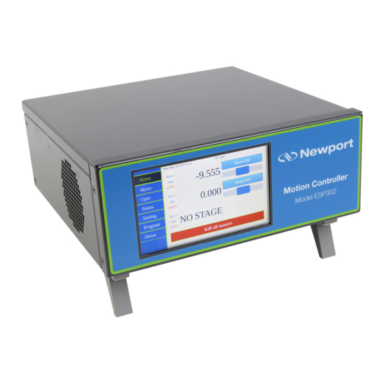
Page 15: Front Panel Description
ESP302 Controller Start-Up Manual Front Panel Description Figure 7: Front panel of ESP302 Controller/Driver. The ESP302 front panel includes a 5" touchscreen for operation in LOCAL mode. Rear Panel Description Figure 8: Rear panel of ESP302 Controller/Driver. NOTE The Main Power ON/OFF Switch is located next to the inlet for the power cord. -
Page 16: Axis Connectors (Axis 1 - Axis 3)
The Ethernet connection provides a local area network through which information is transferred in units known as packets. Communication protocols are necessary to dictate how these packets are sent and received. The ESP302 Controller/Driver supports the industry standard protocol TCP/IP. -
Page 17: Sockets, Multitasking And Multi-User Applications
With the ESP302, it is possible that one axis of the ESP302 controller for an optical delay line, while another axes are simultaneously used for a totally different application. -
Page 18: Getting Started
Getting Started Unpacking and Handling It is recommended that the ESP302 Controller/Driver be unpacked in your lab or work site rather than at the receiving dock. Unpack the system carefully; several cables are included with the equipment. Inspect the box carefully for loose parts before disposing of the packaging. -
Page 19: Rack Mounting Kit
3.4.1 Rack Mounting Kit The ESP302 controller is basically intended to be installed on a flat surface such as a table or a cabinet shelf. A rack mounting kit can be provided separately to properly secure the controller in a standard 19"... - Page 20 ESP302 Controller Start-Up Manual 2 HANDLES 2 PANELS 2x 2 M4x8 SCREWS 2x 2 M5x8 SCREWS 2x 2 M3x6 SCREWS 2 BRACKETS Figure 12: Rear rack mounting. A1270B1 - EDH0411En1021 – 02/20...
-
Page 21: Connecting To The Main
• There is also an Inhibit switch entry with a BNC connector at the rear of the ESP302. An external Inhibit switch can be directly linked by hardware to cut off motor power supply. Refer to section 7.0 for further details on Inhibit connector. If no cable is connected, let the plug in place. -
Page 22: Connecting To The Esp302 Through Comm. Port
2. Network connection. The Ethernet plug identified “HOST” must be used (with static IP or dynamic IP) to connect the ESP302 controller to a Network. Before connection, the controller IP setting must be set by the Network administrator. The following cable is provided with the motion controller. -
Page 23: Direct Connection To The Esp302 Controller
Start-Up Manual 3.7.1 Direct Connection to the ESP302 Controller For a direct connection between a PC and the ESP302 controller you need to use the Ethernet cable and either the REMOTE or the HOST connector at the back of the ESP302. - Page 24 ESP302 Controller Start-Up Manual This procedure is for the Windows 7 operating system (almost similar process for Windows 8): • Start Button > Control Panel > Network and Sharing Center => Change adapter settings. • Right Click on Local Area Connection Icon and select Properties.
- Page 25 If you don’t want to connect the ESP302 controller through a Corporate Network you may skip to section 3.8: “Connecting the Stages“. NOTE If you want to change the HOST IP address of the ESP302 controller, follow the explanation in the next section. A1270B1 - EDH0411En1021 – 02/20...
-
Page 26: Connecting The Esp302 To A Corporate Network Using Static Ip Configuration
ESP302 Controller Start-Up Manual 3.7.2 Connecting the ESP302 to a Corporate Network Using Static IP Configuration Setting HOST static IP address through the front panel • Go to "Setting/Ethernet" tab. • Tick "static IP". • Enter your IP address, Netmask and Gateway. - Page 27 Setting HOST static IP address through the website Once you are logged in using the previously described steps with a direct connection, you can change the IP configuration of the controller in order to connect the ESP302 over a Network.
-
Page 28: Configuring The Esp302 For Connection To A Corporate Network Using Dynamic Ip Configuration
When complete, the IP address selected by your DHCP is displayed on the top of the screen. • In case the ESP302 cannot negotiate an IP address from the DHCP, the search can be stopped by pressing "Cancel (Searching)". The IP address on the top of the screen becomes "None". - Page 29 • Connect to REMOTE plug of the ESP302 as described in section 3.7.1: “Direct Connection to the ESP302 Controller”. • Connect the Ethernet cable to the HOST connector of the ESP302 controller and to your network. • Get to Controller → IP management web page •...
-
Page 30: Recovering A Lost Ip Configuration
Do not use Dynamic IP configuration if your DHCP server uses Windows NT 4.0. 3.7.4 Recovering a Lost IP Configuration If you want to recover a lost IP configuration, simply use the ESP302 front panel and go to "Setting/Ethernet" tab to get the present dynamic IP address allocated by your network. -
Page 31: Testing Your Esp302-Pc Connection And Communication
To check if the ESP302 communicates with to the host computer, send a ping message from the computer to the ESP302. This is done through the Windows menu: Start- >Run->, then type: ping + IP address of the ESP302. See the example below for the IP address 192.168.254.254:... -
Page 32: Connecting The Stages
The cable is terminated with a standard SUB-D25 connector. Configuring the Controller • Power on the controller. Shortly after the power is switched on, the ESP302 will perform a start-up sequence and momentarily display: "Newport ESP302". With ESP-compatible stages, the configuration of each axis is identified automatically by the ESP302 at power up. -
Page 33: Dummy Stages
“Dummy stage” configuration can be used to simulate a stage. This feature allows users to configure and test the system’s behavior without having a real stage connected on the axis. To configure your system with a number of dummy stages see ESP302 User Interface Manual. 3.9.2 Configuration files StageX.ini files:... -
Page 34: Using The Controller
ESP302 Controller Start-Up Manual 3.10 Using the controller Refer to ESP302 User Interface Manual for more information about controller user interface. See also ESP302 Features Manual for explanations about controller functions and operation. 3.11 Documentation Under the webpage Documentation, users can open and download ESP302 manuals and drivers. -
Page 35: Sftp (Secured File Transfer Protocol) Connection
• Enter IP address, login and password • Click Connect The folders of the ESP302 controller are displayed (see below). Browse through the different folders and transfer data from or to your host PC. When connected to the controller with FTP as Administrator, the user has access to configuration files. -
Page 36: Samba Microsoft Smb/Cifs Networking Protocol
ESP302 Controller Start-Up Manual You can also use “puTTY psftp.exe” for secured FTP transfer. 3.13 Samba Microsoft SMB/CIFS Networking Protocol A secured protocol (Samba) has been implemented and also allows the controller Public folder (this folder only) to be attached and detached to the computer as a network drive. -
Page 37: Maintenance And Service
• Snapshot version (VE command or "Controller/General information" on website) • Description of the problem. If the ESP302 is to be returned to Newport Corporation, a Return Number will be issued, which should be referenced in the shipping documents. Complete a copy of the Service Form found at the end of this Manual and include it with your shipment. -
Page 38: Appendix A: Hardware
ESP302 Controller Start-Up Manual Appendix Appendix A: Hardware Controller Weight: 3.0 kg (6.6 lb) Air flow: 17.6 CFM A1270B1 - EDH0411En1021 – 02/20... -
Page 39: Rear Panel Connectors
ESP302 Controller Start-Up Manual Rear Panel Connectors Figure 16: Rear Panel. A1270B1 - EDH0411En1021 – 02/20... -
Page 40: Appendix B: General I/O Description
ESP302 Controller Start-Up Manual Appendix B: General I/O Description This chapter briefly describes all ESP302 signal types and details each of the ESP302 connector interfaces. Digital I/O’s All digital I/Os are TTL compatible: • All digital I/Os are not isolated, but are referenced to electrical ground (GND). -
Page 41: Axes
(GND). • Input levels must be between 0 V and +5 V. All servitude inputs are refreshed synchronously with the ESP302 servo rate. All servitude inputs are identical. All servitude inputs expect normally closed sensors referenced to ground (input is activated if the sensor is open) and have internal 2.2 kΩ... - Page 42 ESP302 Controller Start-Up Manual Motor + This output must be connected to the positive lead of the DC motor. The voltage seen at this pin is pulse-width modulated with maximum amplitude of 47 VDC. Motor - This output must be connected to the negative lead of the DC motor. The voltage seen at this pin is pulse-width modulated with maximum amplitude of 47 VDC.
-
Page 43: Communication Port
ESP302 Controller Start-Up Manual Communication Port 6.3.1 COMM. Connector COMM. NOTE Mating connector: Male SUB-D15HD with UNC4/40 lockers. COMM Pin # Function Pin # Function RS232 RXD reserved RS232 TXD reserved reserved RS232 RTS reserved RS232 CTS reserved reserved RS232 DTR... -
Page 44: Appendix C: Power Inhibit Connector
(If not used, the BNC plug must remain in place to allow operation) The BNC pin is connected to ESP302 inhibit and BNC outer shell is connected to GND. For normal operation of the ESP302, the Inhibit must be connected to GND in order to work. -
Page 45: Service Form
ESP302 Controller Start-Up Manual Service Form Your Local Representative Tel.: __________________ Fax: ___________________ Name: _________________________________________________ Return authorization #: ____________________________________ (Please obtain prior to return of item) Company:_______________________________________________ Address: ________________________________________________ Date: __________________________________________________ Country: ________________________________________________ Phone Number: __________________________________________ P.O. Number: ____________________________________________ Fax Number: ____________________________________________... - Page 46 Visit Newport Online at: www.newport.com North America & Asia Europe Newport Corporation MICRO-CONTROLE Spectra-Physics S.A.S 1791 Deere Ave. 9, rue du Bois Sauvage Irvine, CA 92606, USA 91055 Évry CEDEX France Sales Tel.: (800) 222-6440 Sales e-mail: sales@newport.com Tel.: +33 (0)1.60.91.68.68 Technical Support e-mail: france@newport.com...
Need help?
Do you have a question about the ESP302 and is the answer not in the manual?
Questions and answers