
Subscribe to Our Youtube Channel
Summary of Contents for GAL GALaxy eHydro
- Page 1 GALaxy eHydro Elevator Controller Manual GAL Manufacturing Corporation LLC 50 East 153rd Street Bronx, NY 10451 Technical Support: 1‐877‐425‐7778...
- Page 2 Foreword GAL Manufacturing has developed this manual with usability and safety in mind. General and specific safety notices and precautions are defined in the manual. However, GAL Manufacturing cannot be responsible for any injury to persons or damage to property (including the elevator equipment) resulting from negligence, misuse of the equipment, misinterpretation of instructions included in this manual, or due to any other cause beyond the control of GAL Manufacturing.
-
Page 3: Table Of Contents
Table of Contents GALaxy eHydro Controller Manual………………………………………………………………………………i Foreword...…………………………………………………………………………………………………………...ii Table of Contents………..…………………………………………………………………………………………iii Section 1 - Product Description ......................1-1 Product Code Compliance ......................1-1 Specifications ..........................1-1 Physical Layout of the Controller ....................1-2 Selector System ......................... 1-3 1.4.1 Absolute Position System (APS) Selector ................1-3 1.4.2... - Page 4 3.1.3 Verify the Main CPU is Operating ..................3-1 Start-Up Procedures........................3-2 3.2.1 Requirements for a running platform during initial startup ..........3-2 3.2.2 Complete the Installation of Equipment ................3-4 Adjustment Procedures ......................3-5 3.3.1 Set Toggle Switches ......................3-5 3.3.2 Ready the Car to Run on Inspection ..................
- Page 5 Testing NTSD ..........................8-2 Testing Terminal Speed Reducing Device ................. 8-3 Testing the Load Weighing Device .................... 8-3 Testing Phase 2 Operation With a Ground or Short Circuit ............8-3 Testing Phase 1 & 2 Operation After Power Interruption and Restoration ........ 8-3 Testing Recycling Operation ......................
- Page 6 SYMBOLS USED IN THIS MANUAL CAUTION This manual uses the CAUTION symbol to identify procedures and practices that may result in personal injury and/or equipment damage, if not followed correctly. DANGER This manual uses the DANGER symbol as an alert to a danger of electrocution or an acute electrical shock.
- Page 7 WARNINGS AND CAUTIONARY NOTES Installation and wiring must be in accordance with the national electrical code, all local codes, and all elevator safety codes and standards. The 3‐phase AC power supply to the equipment must originate from a properly fused disconnect or circuit breaker that is properly designed and sized for the specific controller requirements and the “Short Circuit Current Rating”...
- Page 8 Strands not properly inserted into the terminals may make contact with wires from an adjacent terminal. The danger associated with an occurrence as described above has led GAL Manufacturing to recommend that, for all connections to the Electrical Protective Devices listed in ASME A17.1-2016/CSA B44-16, Requirements 2.26.2.1 through 2.26.2.39, elevator personnel must follow the guidelines listed below:...
-
Page 9: Product Description
Section 1 – Product Description GALaxy eHydro Elevator Controller Section 1 - Product Description The GALaxy traction elevator controller is a computer-based system that offers superior performance, flexibility and reliability. It has been designed to save time in installation and troubleshooting, but it is still very important that the field personnel familiarize themselves with this manual before attempting to install the equipment. -
Page 10: Physical Layout Of The Controller
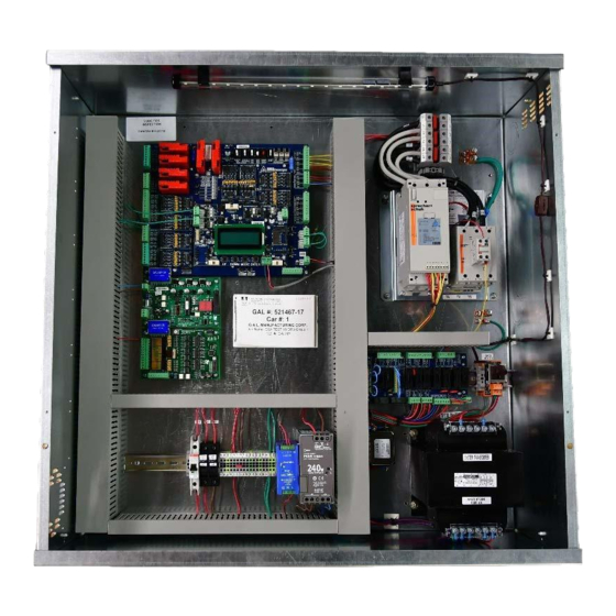
Section 1 – Product Description GALaxy eHydro Elevator Controller 1.3 Physical Layout of the Controller Figure 1-0 shows the general layout of the GALaxy eHydro Controller cabinet. The components in the cabinet include the following items. 1) Main I/O Board:... -
Page 11: Selector System
Section 1 – Product Description GALaxy eHydro Elevator Controller . 1 Main I/O Board . Main CPU 7 . Soft - Starter 3 . PI Driver Board 8 . Power 4 . Car I/O Distribution 5 . Terminal Block 9 . Transformer... -
Page 12: Primary And Secondary Position Feedback
Section 1 – Product Description GALaxy eHydro Elevator Controller Figure 1-1: Absolute Position System Selector 1.4.2 Primary and Secondary Position Feedback The Main CPU receives position feedback from the channel A camera CAN bus and builds a table of floor positions and slowdowns for each floor during setup. On a normal run, the Main CPU uses the slowdown points to initiate a slowdown to the appropriate floor and uses the floor position to determine the door zone and exact stopping position. -
Page 13: Sequence Of Operation
Section 1 – Product Description GALaxy eHydro Elevator Controller while running up to the top terminal floor is the Terminal Speed Device (TSD) limit switch that directly removes power from the up fast valve. The top most limit switch is the Terminal Limit Hatch switch (TLH) that directly removes power from pump motor and all valves. -
Page 14: Modes Of Operation
Section 1 – Product Description GALaxy eHydro Elevator Controller Modes of Operation 1.6.1 Reset Mode Reset mode is initiated when the elevator power is first turned on, or when the system is reset. When the reset mode is initiated, the controller performs internal tests to ensure that both the car and controller are electrically operational before putting the car into service. -
Page 15: Access Mode
Section 1 – Product Description GALaxy eHydro Elevator Controller • Disables access top and access bottom hall switches. • Disables the controller "ENABLE", "UP" and "DOWN" push buttons. • Door locks and Car gates/locks are active and must be closed or the door lock and gate bypass switch or switches must be active to move the car. -
Page 16: Attendant Service Mode
Section 1 – Product Description GALaxy eHydro Elevator Controller 1.6.8 Attendant Service Mode The attendant service mode is initiated by placing the key operated attendant switch located in the car operating panel to the on position. Attendant mode permits operation of the car with an attendant. This mode performs the following operations: •... -
Page 17: Fire Service Phase I Alternate Return Mode
Section 1 – Product Description GALaxy eHydro Elevator Controller • If the car is at a landing with the doors open, the doors will close, and the car will return non- stop to the primary return floor. • If the car is traveling away from the primary return floor, the car will stop at the next landing, and then go immediately to the primary return floor. -
Page 18: Emergency Power Battery Lowering
Section 1 – Product Description GALaxy eHydro Elevator Controller • If a car is selected to run it will go back into normal operation. • Removing the connection between terminals “HC” and “EMP” will remove the cars from emergency power operation. -
Page 19: Installation
Section 2 –Installation GALaxy eHydro Elevator Controller Section 2 - Installation 2.1 General Information This section provides basic guidelines and recommendations for the proper installation of the controller equipment. These guidelines should be used as general instructions. They are not intended to usurp local codes and regulations. -
Page 20: Wiring Schematics
Strands not properly inserted into the terminals may make contact with wires from an adjacent terminal. The danger associated with an occurrence as described above has led GAL Manufacturing to recommend that, for all connections to the Electrical Protective Devices listed in ASME A17.1- 2016/CSA B44-16, Requirements 2.26.2.1 through 2.26.2.39, elevator personnel must follow the... -
Page 21: Elevator Car Wiring
The Top Terminal Slowdown limits are used to prevent the car from hitting the stop ring on the hydraulic jack at a speed greater 50 fpm. TSD and TLH limits must be mechanical switches installed on all GALaxy eHydro controlled elevators and must be set to activate mechanically from the movement of the car. -
Page 22: Top Terminal Limit Switches
The Terminal Slowdown (TSD) switch should be set to open at the appropriate table value. These two switches must be mechanical switches. For the requirements for a running platform during initial start-up, refer to the GALaxy eHydro Quickstart Guide or Section 3.2.1 of this manual. - Page 23 Section 2 –Installation GALaxy eHydro Elevator Controller Camera and Cam mounted on the Elevator Figure 2-0: APS Selector General Configuration...
- Page 24 Section 2 –Installation GALaxy eHydro Elevator Controller To install the APS Selector, follow steps 1 through 8 below: Step 1: Install top selector bracket and attach the encoded tape. • Mount the top J-hook selector bracket to the rail. •...
- Page 25 Section 2 –Installation GALaxy eHydro Elevator Controller Figure 2-2: Front View of Encoded Tape Figure 2-3: Side View of Top Bracket Step 2: Run down on inspection while unrolling the encoded tape. • Run down on inspection while unrolling the tape. See Figure 2-4.
- Page 26 Section 2 –Installation GALaxy eHydro Elevator Controller Figure 2-4: Unroll the Encoded Tape Figure 2-6: Guide Clip without Figure 2-5: Guide Clip with Door Zone Bridge Door Zone Bridge Step 3: Install the bottom selector bracket and attach the encoded tape.
- Page 27 Section 2 –Installation GALaxy eHydro Elevator Controller Figure 2-7: Lower Bracket Mounting Figure 2-8: Side View of Encoded Tape Attachment to the Bottom Bracket...
- Page 28 Section 2 –Installation GALaxy eHydro Elevator Controller Figure 2-9: Lower Bracket with Springs Properly Compressed to the Marks Step 4: Install the selector mounting bracket. • Mount the selector mounting bracket to the cross head. • Use the roller or slide shoe guide bolts to hold the camera bracket. The face of the bracket should be about 5 ½...
- Page 29 Section 2 –Installation GALaxy eHydro Elevator Controller Figure 2-11: Top View of APS Camera and Mounting Bracket Step 5: Install the APS Camera. • Mount the camera on the mounting bracket. • The APS camera should be centered with the encoded tape.
- Page 30 Section 2 –Installation GALaxy eHydro Elevator Controller Step 6: Wire the APS Selector Camera according to the connection diagrams. • The APS selector should be wired according to the job specific wiring schematic and connection diagrams. See Figure 2-11. Figure 2-13: Wire APS Camera According to Wiring Schematic and Connection Diagram Prior to performing “Step 7”...
- Page 31 Section 2 –Installation GALaxy eHydro Elevator Controller Figure 2-15: APS Camera Alignment Figure 2-14: LED Array on Spotlights APS Camera Color Function Slow Blinking (1 Hz) Fast Blinking (5 Hz) Green Supply voltage No power Power OK STAT Status signal...
-
Page 32: Aps Selector Floor Position Setup (Hoistway Learn)
Section 2 –Installation GALaxy eHydro Elevator Controller Figure 2-17: APS Camera Orientation 2.7.2 APS Selector Floor Position Setup (Hoistway Learn) The hoistway learn procedure requires that the selector camera communicates properly with the Main CPU and the NTS processor. The hoistway learn procedure also requires that the APS camera module communicates properly with both CPUs on the selector interface board and with the main CPU in the controller. -
Page 33: Set The Adjustable Variables - "Nts Proc Adj Vars" In The Controller
Section 2 –Installation GALaxy eHydro Elevator Controller Set the Adjustable Variables – “NTS Proc Adj Vars” in the Controller. 2.7.2.2 The following parameters must be setup prior to learning any floor positions. • Set “Top Speed” to the contract speed of the job. -
Page 34: Setting Hoistway Floor Levels With Aps Selector
Section 2 –Installation GALaxy eHydro Elevator Controller 2.7.2.4 Setting Hoistway Floor Levels with APS Selector • Put the elevator on car top inspection. Temporarily set the car door bypass switch to the BYPASS position. Setting the car door bypass switch to the BYPASS position will allow the car to be moved on car top inspection with the car door open. - Page 35 Section 2 –Installation GALaxy eHydro Elevator Controller • Move the car on inspection so that it is exactly level with a floor. Pressing the door open button, while moving the car on inspection, will change the inspection speed to 3 fpm during the inspection run. This allows the car to be positioned at exactly floor level.
- Page 36 Section 2 –Installation GALaxy eHydro Elevator Controller • To record the floor position, press the buttons on the car operating panel in the following sequence. Press the 2 floor car call button Press the 1 floor car call button Press the 2...
-
Page 37: Galaxy Startup And Adjustment
Section 3 – GALaxy Startup and Adjustment GALaxy eHydro Elevator Controller Section 3 - GALaxy Startup and Adjustment 3.1 Procedure for Initial Power-up of Controller 3.1.1 Checking Main Line Voltage Prior to powering up the controller or attempting to run the hydraulic pump motor, the following steps should be completed: •... -
Page 38: Start-Up Procedures
Section 3 – GALaxy Startup and Adjustment GALaxy eHydro Elevator Controller Start-Up Procedures 3.2.1 Requirements for a running platform during initial startup Wire Hydraulic Pumping Unit and Main Line Power as shown in the job connection diagrams. If elevator requires a Governor, install and wire the Governor as shown in the job connection diagrams. - Page 39 Section 3 – GALaxy Startup and Adjustment GALaxy eHydro Elevator Controller Figure 3-1 For Run Bug Connections Figure 3-2: GALX-1121 Main I/O Board...
-
Page 40: Complete The Installation Of Equipment
Section 3 – GALaxy Startup and Adjustment GALaxy eHydro Elevator Controller Check/set parameters in the controller LCD user interface. See “eHydro Controller Settings” in Table 3-0. Preset the following parameters from the LCD User Interface “Adjustable Variables” menu. Adjustable Variables - Car Motion Adjustable Variables - System Options APS Dead Zone = 0.25 inches... -
Page 41: Adjustment Procedures
Section 3 – GALaxy Startup and Adjustment GALaxy eHydro Elevator Controller 3.3 Adjustment Procedures • Remove all temporary connections. • Verify that all safety circuits and safety devices are installed and functioning properly. • Verify that all car door electric contacts or car door interlocks are functioning properly. -
Page 42: Prepare For The Car For Hoistway Learn
Section 3 – GALaxy Startup and Adjustment GALaxy eHydro Elevator Controller Figure 3-3: Inspection String Circuit 3.3.3 Prepare for the Car for Hoistway Learn Return to section 2.7.2.1, “Veirfy that the APS Selector Camera is installed Correctly and Communicating”. Complete sections 2.7.2.1 through 2.7.2.4. After completing section 2.7.2.4,... -
Page 43: Verify The Hoistway
Section 3 – GALaxy Startup and Adjustment GALaxy eHydro Elevator Controller • Place the RUN/SETUP jumper on the GALX-1134AN COP Interface Board to the RUN position. Place the CN18 jumper on the GALX-1121An MAIN I/O board to No Test Mode 1 – 2. -
Page 44: Adjust The Slowdown Distances
Section 3 – GALaxy Startup and Adjustment GALaxy eHydro Elevator Controller • Press ENTER, select a car call floor and press ENTER again. The elevator should run to answer the call. • When the elevator levels in and stops at the floor, the doors will remain closed. The speed of the car can be monitored on this screen with each run as well as the pump motor “... -
Page 45: Adjust The Stop
Section 3 – GALaxy Startup and Adjustment GALaxy eHydro Elevator Controller Count" display. See Figure 3-6. From this screen, Down Slowdown (DS) count, the floor count and Up Slowdown (US) count can be set. Figure 3-6: Accel/Decel Display Press UP or DOWN to access the desired floor and then press ENTER to go into edit mode. Use the UP and DOWN buttons to position the cursor “>”... -
Page 46: Verify Proper Operation Of All Safety Circuits And Signal Devices
Section 3 – GALaxy Startup and Adjustment GALaxy eHydro Elevator Controller To make floor position count changes at individual floors select the "Hoistway Tables" menu and then the "Floor & SD Count" screen. See Figure 3-8. Hit UP or DOWN to access the desired floor and then press ENTER to go into edit mode. -
Page 47: Troubleshooting
GALaxy eHydro Elevator Controller Section 4 - Troubleshooting Section 4 Troubleshooting 4.1 General Information The GALaxy controller is equipped with a number of features that aid in troubleshooting any problems that may occur. The physical layout of the controller provides ready access to all I/O to make voltage measurements. -
Page 48: Run Sequence
GALaxy eHydro Elevator Controller Section 4 - Troubleshooting All of the I/O’s are optically isolated between the high voltage section and the low voltage section. The inputs on the GALX-1121 Main I/O board and the GALX-1134 COP board are separated into 8 inputs per board (GALX4-0048N input board) that mounts on the larger boards. -
Page 49: The Safety Pal Functions
GALaxy eHydro Elevator Controller Section 4 - Troubleshooting 4.5 The Safety PAL Functions The Safety PAL monitors the Main CPU RUN and Door Zone outputs, the NTS Terminal Limit and Door Zone outputs, car Inspection and Door Gate/Lock inputs, and the speed outputs from both the Main CPU and the NTS. - Page 50 GALaxy eHydro Elevator Controller Section 4 - Troubleshooting Figure 4-1: Main CPU, NTS and Safety PAL System...
-
Page 51: Safety Pal
GALaxy eHydro Elevator Controller Section 4 - Troubleshooting Figure 4-2: GALX-1121 Main I/O Board 4.6 Safety PAL The Safety PAL has a fault LED located in the middle left of the board that indicates there is a PAL fault. See Figure 4-2. -
Page 52: System Faults
GALaxy eHydro Elevator Controller Section 4 - Troubleshooting System Faults Faults that are detected by the Main CPU can be viewed on the Main CPU LCD interface by navigating to the "Fault Log" menu, "View Fault Log". The lists of possible faults detected by the Main CPU are listed in section 6, Main CPU Faults. - Page 53 GALaxy eHydro Elevator Controller Section 4 - Troubleshooting Table 4-1: Main CPU Inputs & Outputs Name Description Cab Down Lantern Output Counter Weight Collision Switch Input (Traction Elevators) In Car Stop Switch Input Car Spare Input 1 – 3 CSPI1-3 Car Spare Output 1 –...
- Page 54 GALaxy eHydro Elevator Controller Section 4 - Troubleshooting Table 4-1: Main CPU Inputs & Outputs Name Description DT-1 or DTc Down Terminal Slowdown Output from Main CPU position reference Door Zone Input from Safety PAL (And of NTS and Main CPU)
- Page 55 GALaxy eHydro Elevator Controller Section 4 - Troubleshooting Table 4-1: Main CPU Inputs & Outputs Name Description In-Car Inspection Input. Inconspicuous Riser Input Car top Inspection Down Input Car Top Inspection Enable Inspection Fire Buzzer Output Inspection Fire Light Output...
- Page 56 GALaxy eHydro Elevator Controller Section 4 - Troubleshooting Table 4-1: Main CPU Inputs & Outputs Name Description Door Nudging Output NUDR Door Nudging Rear Output Overload Input 1ST – Nth Discrete Floor Position Indicator Outputs P1-Pn PALF Safety PAL Fault...
-
Page 57: Nts Processor Inputs And Outputs
GALaxy eHydro Elevator Controller Section 4 - Troubleshooting Table 4-1: Main CPU Inputs & Outputs Name Description TSTM Test Mode Jumper Up Direction Arrow Output UL or ULc Up Level Position from Main CPU position reference ULO or ULcO Up Level Output LED from Main CPU... -
Page 58: Relocate I/Os
GALaxy eHydro Elevator Controller Section 4 - Troubleshooting 4.10 Relocate I/Os Special Relocation I/O’s are located on the Machine Room CAN bus, the Car Top CAN bus and the Group CAN bus. Each CAN bus has three inputs and three outputs for this purpose and are named as... -
Page 59: Relocate I/Os - Add Io Relocation
GALaxy eHydro Elevator Controller Section 4 - Troubleshooting 4.10.1 Relocate I/Os – Add IO Relocation Figure 4-3: To relocate the I/O, select the “Relocate IOs” menu from the “Inputs and Outputs” menu. Then select the “Add I/O Relocation”. Use the Up or Down button to select the input type and location such as CSPI1, (CTCAN car spare input 1). -
Page 60: Relocate I/Os - Remove Relocation Io
GALaxy eHydro Elevator Controller Section 4 - Troubleshooting the Enter button again. Once an I/O has been selected, power must be cycled on the controller for the relocation to take place. 4.10.2 Relocate I/Os – Remove Relocation IO Figure 4-4: To remove an individual I/O from the relocation table, select the “Remove Relocation IO”... -
Page 61: Car Trace Screen
GALaxy eHydro Elevator Controller Section 4 - Troubleshooting 4.10.3 Car Trace Screen The controller continually stores 168 bytes of critical data every 20 milliseconds (can be set to 10, 20, 30 or 40) in a 500-frame circular trace buffer. This continues until a command is given to stop storing in which 35 additional frames are stored and then the update is stopped. - Page 62 GALaxy eHydro Elevator Controller Section 4 - Troubleshooting A description of each trace setup menu is show below: • Stop Trace – Stops the trace recording. • Start Trace – Starts the trace recording. • Trace Time Interval – Modify the time interval from 10 to 20, 30 or 40 msec. Extends the trace time from 5 seconds to 10, 15 or 20 seconds respectively.
- Page 63 GALaxy eHydro Elevator Controller Section 4 - Troubleshooting • Show Trace Trigger Logic – Displays the trace trigger logic. • Clear Trace Trigger Logic – Clears the trace trigger logic. The Trace Screen is the “Elevator Status Screen” but it is not being continuously updated. Instead the trace screen allows the user to step through each buffer frame to catch extremely quick changes in the status while the car was running.
- Page 64 GALaxy eHydro Elevator Controller Section 4 - Troubleshooting 20 milliseconds later. If the time interval is set to 10 milliseconds, then the next frame displayed would show data that is 10 milliseconds later. Note, changing the time interval while the trace is stopped will cause the trace data to be lost and the trace will be restarted.
-
Page 65: Lcd Interface
Section 5 – LCD Interface GALaxy eHydro Elevator Controller Section 5 LCD Interface 5.1 Operating the LDC Interface Figure 5-0: LCD Interface The LCD interface uses a 4 line by 20-character display and four buttons. This interface allows the user to adjust parameters, view critical controller information, to implement the controller setup and to view the elevator status. -
Page 66: Lcd Menus
Section 5 – LCD Interface GALaxy eHydro Elevator Controller LCD Menus 5.2.1 Elevator Status Figure 5-1:... - Page 67 Section 5 – LCD Interface GALaxy eHydro Elevator Controller 5.2.1.1 Elevator Status Screens: The Elevator Status Display is show immediately after a power up. Critical information for the controller is displayed in several screens that are continuously updated. These screens show the car status, control I/O’s and fault information.
- Page 68 Section 5 – LCD Interface GALaxy eHydro Elevator Controller Table 5-0: Elevator Service = (SAF) Safety String = (LPR) Low Pressure = (INS) Inspection = (HOT) Hot Oil Operation = (RST) Reset Mode = (ADO) Auto Door Off = (TST) Test Mode Service...
- Page 69 Section 5 – LCD Interface GALaxy eHydro Elevator Controller When a system fault occurs, it will be displayed on the bottom line of the second status display screen in place of “No Current Fault”. The fault will remain for 60 seconds if not additional fault occurs.
- Page 70 Section 5 – LCD Interface GALaxy eHydro Elevator Controller Table 5-5: STATUSF: Control Status Flag (Pops up over current fault) Bit 0: (sfS10) NO S10 power Bit 17: Bit 1: (sfHC) NO HC power Bit 18: Bit 2: (sfSS) NO SS input...
- Page 71 Section 5 – LCD Interface GALaxy eHydro Elevator Controller Table 5-7: STATUSF3: Control Status Flag (Pops up over current fault) Bit 0: Bit 16: Bit 1: Bit 17: Bit 2: Bit 18: Bit 3: (sfASC) APS Selector CAN Fault Bit 19:...
- Page 72 Section 5 – LCD Interface GALaxy eHydro Elevator Controller Table 5-7: CkStS: Check Start Status State 0 = No Start Op 20 = SUF Fail Off 1 = CCF Off Up 21 = SUF On w/SU 2 = CPU UN Off...
- Page 73 Section 5 – LCD Interface GALaxy eHydro Elevator Controller Table 5-9: CkDrS: Check Door Status State 0 = No Door Op 21 = At Floor Chk 1 = Fire Door 22 = Front DPM 2 = Med Em Svc 23 = Rear DPM...
- Page 74 Section 5 – LCD Interface GALaxy eHydro Elevator Controller 5.2.1.2 Car Call Popup Display From any screen on the Elevator Status display, hitting Enter cause a Car Call Popup display to appear. Use the Up and Down buttons to select the desired car call and then press Enter to activate the call.
- Page 75 Section 5 – LCD Interface GALaxy eHydro Elevator Controller 5.2.1.4 Trace Display The controller continually stores 168 bytes of critical data every 20 milliseconds (can be changed to 10, 20, 30 or 40) in a 500-frame circular trace buffer. This continues until a command is given to stop storing data in which 35 additional frames are stored and then the update is stopped.
-
Page 76: Main Menu
Section 5 – LCD Interface GALaxy eHydro Elevator Controller 5.2.2 Main Menu The LCD Main Menu give the user access to all parameters and diagnostics information. Once in the menu from the exiting the Elevator Status Screen, the menu is accessed from the UP, DOWN, MODE and ENTER buttons. -
Page 77: Date And Time
Section 5 – LCD Interface GALaxy eHydro Elevator Controller 5.2.3 Date and Time The Date and Time menu allows the user to set the controller real-time calendar clock date and time. It is important to set the date and time to local values so that all faults are displayed in the fault log with accurate information. -
Page 78: Set Calls And Lockouts
Section 5 – LCD Interface GALaxy eHydro Elevator Controller 5.2.4 Set Calls and Lockouts 5.2.4.1 Set Car Calls The user can set car and hall calls from the Set Calls & Lockout menu. Note that hall call can only be set from this menu if this car is acting as the group car. - Page 79 Section 5 – LCD Interface GALaxy eHydro Elevator Controller 5.2.4.2 Car Call Lockouts The Car Call can be locked out from the Car Call Lockout menu. Select the floor using the UP and DOWN buttons and then hit ENTER to lockout the call. The locked-out call will display an asterisk next to the floor number.
- Page 80 Section 5 – LCD Interface GALaxy eHydro Elevator Controller 5.2.4.3 Car Call Test This menu allows the mechanic to initiate a continuous test of the elevator. The test can be conducted with the “AUTO DOORS” switch set to “ON” or “OFF”. By following the instructions from the menu, the “Car Call Test”...
-
Page 81: Inputs And Outputs
Section 5 – LCD Interface GALaxy eHydro Elevator Controller 5.2.5 Inputs and Outputs The Input and Output menus show the status of all inputs and outputs for the MAIN CPU, the GROUP, the NTS processor and the Safety PAL. The status of the I/O is shown as a closed diamond “ ” for ON and an open diamond “... - Page 82 Section 5 – LCD Interface GALaxy eHydro Elevator Controller 5.2.5.1 Relocate I/Os The Relocation I/O menus allow the user to relocate up to three inputs and three outputs on each of the Machine Room CAN bus, the Car Top CAN and the Group CAN bus. Details of relocating the I/Os are described in the troubleshooting section of this manual.
- Page 83 Section 5 – LCD Interface GALaxy eHydro Elevator Controller 5.2.5.2 Remove Relocation I/O Figure 5-16: 5-19...
-
Page 84: Job Statistics
Section 5 – LCD Interface GALaxy eHydro Elevator Controller 5.2.6 Job Statistics The Job Statistics menu shows the number car calls and the number and percent of hall calls serviced since the job was started or since the job statistics were cleared. -
Page 85: Adjustable Variables
Section 5 – LCD Interface GALaxy eHydro Elevator Controller 5.2.7 Adjustable Variables This Adjustable Variables menu allows modification of numerous field adjustable parameters for the Main CPU and the NTS Processor. Refer to the Adjustable Variables section for a list of all parameters and their functions. -
Page 86: Diagnostics
Section 5 – LCD Interface GALaxy eHydro Elevator Controller 5.2.8 Diagnostics The diagnostics menu shows the communications status to all serial devices. For most devices, the device version and the transmit/receive counts are displayed. The transmit/receive counts should always be incrementing for all devices. All CAN bus communications ports show a “TxErr” and “RxErr”... - Page 87 Section 5 – LCD Interface GALaxy eHydro Elevator Controller 5.2.8.1 Group Comm Status Figure 5-20: 5-23...
- Page 88 Section 5 – LCD Interface GALaxy eHydro Elevator Controller 5.2.8.2 Group Can Comm Status Figure 5-21: 5-24...
- Page 89 Section 5 – LCD Interface GALaxy eHydro Elevator Controller 5.2.8.3 Car Can Comm Status Figure 5-22: 5-25...
- Page 90 Section 5 – LCD Interface GALaxy eHydro Elevator Controller 5.2.8.4 Machine Room Can Comm Status Figure 5-23: 5-26...
- Page 91 Section 5 – LCD Interface GALaxy eHydro Elevator Controller 5.2.8.5 SPI Comm Status Figure 5-24: 5-27...
- Page 92 Section 5 – LCD Interface GALaxy eHydro Elevator Controller 5.2.8.6 APS Selector Comm Status Figure 5-25: 5.2.8.7 Hall Lantern Comm Status Figure 5-26: 5-28...
-
Page 93: Software Utilities
Section 5 – LCD Interface GALaxy eHydro Elevator Controller 5.2.9 Software Utilities The software utilities menu allows the user to view the controller software version, run power-up mode, test the CPU watchdog timer, access SD Card operations, access WiFi setup, change the floor PIs, setup the trace buffer trigger conditions and copy floor tables to the NTS processor. - Page 94 Section 5 – LCD Interface GALaxy eHydro Elevator Controller Reset Debug Variables: The debug variables are set by a software engineer to aid in debugging a software problem. Some problems are especially difficult to catch because they occur infrequently or at seemingly random times.
- Page 95 Section 5 – LCD Interface GALaxy eHydro Elevator Controller 5.2.9.2 Power-Up Mode When the Main CPU powers up, it runs a power-up routine that verifies the checksum of the controller program in local flash memory and then verifies that the job configuration file is on the SD Card. If all is okay, the power-up routine jumps to the controller program.
- Page 96 Section 5 – LCD Interface GALaxy eHydro Elevator Controller 5.2.9.3 Update Verify Program This menu is used to check the integrity of the CONS file, the controller program and the SD card itself. It is also used to update the controller software. To update controller software, make sure the car is on inspection, make sure the SD Card is installed with the latest controller software and then follow the menu to Load SD Card Program.
-
Page 97: Hoistway Tables
Section 5 – LCD Interface GALaxy eHydro Elevator Controller 5.2.10 Hoistway Tables The Hoistway Tables menu show the normal Floor Position Count, normal Slowdown Counts, the Short Floor Slowdown Counts, the CPU Terminal Limit Distanced Counts, the UL and DL Distances Counts for the Main CPU and the Valid Floors and Clips for the NTS Processor. - Page 98 Section 5 – LCD Interface GALaxy eHydro Elevator Controller 5.2.10.1 Floor & Slowdown Counts This menu is useful for checking the position count and set the slowdown count values for each floor. Use the UP and DOWN buttons to select the floor and then ENTER to edit values for that floor.
- Page 99 Section 5 – LCD Interface GALaxy eHydro Elevator Controller 5.2.10.2 CPU Terminal Limit Distance The CPU Terminal Limit Distance Counts show the Main CPU’s normal terminal limit slowdown values. When the hoistway learn is completed, this table is updated according to the car velocity and will match the slowdown value that are used by the NTS processor.
- Page 100 Section 5 – LCD Interface GALaxy eHydro Elevator Controller 5.2.10.4 NTS Valid Floors & Clips The NTS Valid Floors and Clips menu shows the valid floors learned in the NTS Processor’s hoistway table during setup and the valid clips read at each floor while running. The clip locations are learned after the car has been setup and is running on automatic at which time the NTS Processor creates a table of floors with valid clips.
- Page 101 Section 5 – LCD Interface GALaxy eHydro Elevator Controller 5.2.10.6 Learn Hoistway The controller uses an absolute position tape to maintain the position of the elevator. There are two mechanisms to learn the position count for each floor, one from the machine room using this menu and the second from the car operating station with the COP setup jumper installed.
- Page 102 Section 5 – LCD Interface GALaxy eHydro Elevator Controller 5.2.10.7 Open/Close Door The menu is used to open or close the front or rear door while the car is in a valid door zone and the car is on inspection.
-
Page 103: Fault Log
Section 5 – LCD Interface GALaxy eHydro Elevator Controller 5.2.11 Fault Log This menu allows the user to view or clear the fault log. The View Fault Log menu displays the fault, the car PI “P”, the building floor position “F”, the number of occurrences, the car service, time and date the fault occurred and the process mode. -
Page 104: Main Cpu Faults & Detailed Faults
Section 6 – Main CPU Faults & Detailed Faults GALaxy eHydro Elevator Controller Section 6 - Main CPU Faults & Detailed Faults 6.1 Main CPU Faults Table 6-0: Main CPU Faults Faults Description Possible Cause/Suggested Fix • From the LCD user interface, select the Diagnostic menu and then the Sel CAN Com Status menu. - Page 105 Section 6 – Main CPU Faults & Detailed Faults GALaxy eHydro Elevator Controller Table 6-0: Main CPU Faults Faults Description Possible Cause/Suggested Fix • From the LCD user interface, select the Diagnostic menu APS (Absolute Position and then the Sel CAN Com Status menu. The Rx Error Cnt System) Selector should be zero and the Rx Data Cnt should be incrementing.
- Page 106 Section 6 – Main CPU Faults & Detailed Faults GALaxy eHydro Elevator Controller Table 6-0: Main CPU Faults Faults Description Possible Cause/Suggested Fix • Car faulted out while at floor. Look at the fault log for a At Floor Shutdown...
- Page 107 Section 6 – Main CPU Faults & Detailed Faults GALaxy eHydro Elevator Controller Table 6-0: Main CPU Faults Faults Description Possible Cause/Suggested Fix • Faulty wiring from R/T+ and R/T- from car to car. The group car is not • Faulty U6 driver chip on 1132 board.
- Page 108 Section 6 – Main CPU Faults & Detailed Faults GALaxy eHydro Elevator Controller Table 6-0: Main CPU Faults Faults Description Possible Cause/Suggested Fix • Faulty wiring from R/T+ and R/T- from car to car. The group car is not • Faulty U6 driver chip on 1132 board.
- Page 109 Section 6 – Main CPU Faults & Detailed Faults GALaxy eHydro Elevator Controller Table 6-0: Main CPU Faults Faults Description Possible Cause/Suggested Fix Car Safety Switch Car Safety Sw. Fault • Verify that the car safety is not tripped. Fault •...
- Page 110 Section 6 – Main CPU Faults & Detailed Faults GALaxy eHydro Elevator Controller Table 6-0: Main CPU Faults Faults Description Possible Cause/Suggested Fix Contact Confirm Fault input failed off. This • Faulty CCF input. Replace the input board. input is used with an CCF Input Failed Off •...
- Page 111 Section 6 – Main CPU Faults & Detailed Faults GALaxy eHydro Elevator Controller Table 6-0: Main CPU Faults Faults Description Possible Cause/Suggested Fix CFLT Input Failed ON. The soft-starter fault relay is check once a day from the • Faulty soft-starter fault relay. Replace the fault relay.
- Page 112 Section 6 – Main CPU Faults & Detailed Faults GALaxy eHydro Elevator Controller Table 6-0: Main CPU Faults Faults Description Possible Cause/Suggested Fix CPU DN-1 Failed Off during start or • Faulty Communications with the APS selector. Check for leveling. The APS selector CAN faults.
- Page 113 Section 6 – Main CPU Faults & Detailed Faults GALaxy eHydro Elevator Controller Table 6-0: Main CPU Faults Faults Description Possible Cause/Suggested Fix Device on the Car Top CAN Port has a Fault. On the LCD Interface, • Look at the details of the fault. The device name and the...
- Page 114 Section 6 – Main CPU Faults & Detailed Faults GALaxy eHydro Elevator Controller Table 6-0: Main CPU Faults Faults Description Possible Cause/Suggested Fix • The Safety PAL detected a fault condition and turned off Car unexpectedly hit the UN output from the NTS processor.
- Page 115 Section 6 – Main CPU Faults & Detailed Faults GALaxy eHydro Elevator Controller Table 6-0: Main CPU Faults Faults Description Possible Cause/Suggested Fix • The DZ/DZp output from the SAFETY PAL comes from the Door Zone Off Fault combination of the following signals: NTS dz output, NTS...
- Page 116 Section 6 – Main CPU Faults & Detailed Faults GALaxy eHydro Elevator Controller Table 6-0: Main CPU Faults Faults Description Possible Cause/Suggested Fix • The DT limit from the NTS processor is too far from the DT Limit from the NTS bottom landing.
- Page 117 Section 6 – Main CPU Faults & Detailed Faults GALaxy eHydro Elevator Controller Table 6-0: Main CPU Faults Faults Description Possible Cause/Suggested Fix Electric Eye Test. • Verify that the electric eye input EE2 is off before the EE Tst EE2 Freight door electric electric eye test.
- Page 118 Section 6 – Main CPU Faults & Detailed Faults GALaxy eHydro Elevator Controller Table 6-0: Main CPU Faults Faults Description Possible Cause/Suggested Fix Emergency Power Recall Car Out of Service Car 2. Car 2 EP Recall Car 2 OTS was out of service •...
- Page 119 Section 6 – Main CPU Faults & Detailed Faults GALaxy eHydro Elevator Controller Table 6-0: Main CPU Faults Faults Description Possible Cause/Suggested Fix Emergency Power Recall Car Out of Service Car 7. Car 7 EP Recall Car 7 OTS was out of service •...
- Page 120 Section 6 – Main CPU Faults & Detailed Faults GALaxy eHydro Elevator Controller Table 6-0: Main CPU Faults Faults Description Possible Cause/Suggested Fix Emergency Power • Make sure the field variable 'Recall Timeout' is set Recall Time-out Car 5. EPRecall Car5 Tim-ot...
- Page 121 Section 6 – Main CPU Faults & Detailed Faults GALaxy eHydro Elevator Controller Table 6-0: Main CPU Faults Faults Description Possible Cause/Suggested Fix Fire/Emergency Circuit FEP Fuse Blown Fault • Short Circuit on the FEP Circuit. Refer to the schematic Fuse is Blown and check the circuit with a meter.
- Page 122 Section 6 – Main CPU Faults & Detailed Faults GALaxy eHydro Elevator Controller Table 6-0: Main CPU Faults Faults Description Possible Cause/Suggested Fix The FSTP input on the FSTP I/O • Faulty FST1 output chip. Replace output chip. 1134 COP board did Failed Off •...
- Page 123 Section 6 – Main CPU Faults & Detailed Faults GALaxy eHydro Elevator Controller Table 6-0: Main CPU Faults Faults Description Possible Cause/Suggested Fix Field Variables Backup Table Error. The field variables from the backup MRAM table • A once-in-a-while occurrence of this error can be ignored...
- Page 124 Section 6 – Main CPU Faults & Detailed Faults GALaxy eHydro Elevator Controller Table 6-0: Main CPU Faults Faults Description Possible Cause/Suggested Fix Field Variables Table Checksum Error. The verification checksum for the main field variable table has failed. During power...
- Page 125 • Faulty U6 driver chip on the GALX-1132 CPU board (next to acting as the group car Group Comm Loss the connector for the group comm). Call GAL. has stopped • Noise on shield wire. Connect shield only on one end.
- Page 126 Section 6 – Main CPU Faults & Detailed Faults GALaxy eHydro Elevator Controller Table 6-0: Main CPU Faults Faults Description Possible Cause/Suggested Fix • Cable is bad or disconnected The Hall Call Driver • Cables going to wrong port (i.e., switched TO ABOVE and...
- Page 127 Section 6 – Main CPU Faults & Detailed Faults GALaxy eHydro Elevator Controller Table 6-0: Main CPU Faults Faults Description Possible Cause/Suggested Fix The Hall Call Driver • Cable connecting two devices could be flip- flopped (i.e., Board cannot gray wire goes from pin 1 on one end to pin 8 on the other internally read end).
- Page 128 Section 6 – Main CPU Faults & Detailed Faults GALaxy eHydro Elevator Controller Table 6-0: Main CPU Faults Faults Description Possible Cause/Suggested Fix Hoistway Update Initialization. Table of door zone positions • Job related hoistway setup information is invalid. This...
- Page 129 Section 6 – Main CPU Faults & Detailed Faults GALaxy eHydro Elevator Controller Table 6-0: Main CPU Faults Faults Description Possible Cause/Suggested Fix Inspection High Speed I/O Failed Off. This IHS I/O • Faulty IHS input. Replace or relocate the input board.
- Page 130 Section 6 – Main CPU Faults & Detailed Faults GALaxy eHydro Elevator Controller Table 6-0: Main CPU Faults Faults Description Possible Cause/Suggested Fix • Invalid hoistway learn or the hoistway learn is not Invalid DN or DT complete. Re-learn the hoistway or complete the hoistway Count.
- Page 131 Section 6 – Main CPU Faults & Detailed Faults GALaxy eHydro Elevator Controller Table 6-0: Main CPU Faults Faults Description Possible Cause/Suggested Fix • Invalid load weigher table on power up. The load weigher table will be re-initialized to zero and the load weigher must...
- Page 132 Section 6 – Main CPU Faults & Detailed Faults GALaxy eHydro Elevator Controller Table 6-0: Main CPU Faults Faults Description Possible Cause/Suggested Fix • Faulty MCCi input chip. Replace input chip. MC I/O The MC input or • Faulty MCC output chip. Replace output chip.
- Page 133 Section 6 – Main CPU Faults & Detailed Faults GALaxy eHydro Elevator Controller Table 6-0: Main CPU Faults Faults Description Possible Cause/Suggested Fix MRCan Bus Off Error. The Can bus has been • Faulty CAN bus wiring. Check the Can bus terminal...
- Page 134 Section 6 – Main CPU Faults & Detailed Faults GALaxy eHydro Elevator Controller Table 6-0: Main CPU Faults Faults Description Possible Cause/Suggested Fix NTS DN I/O Failed On during start. As part of the redundancy check, the Main CPU sends a...
- Page 135 Section 6 – Main CPU Faults & Detailed Faults GALaxy eHydro Elevator Controller Table 6-0: Main CPU Faults Faults Description Possible Cause/Suggested Fix • The UN output failed. Replace the UN output module.• NTS UN I/O Failed Off The UN input failed. Replace the UN input board.• The NTS during start or processor has turned the UN output off.
- Page 136 Section 6 – Main CPU Faults & Detailed Faults GALaxy eHydro Elevator Controller Table 6-0: Main CPU Faults Faults Description Possible Cause/Suggested Fix NTS UT I/O Failed On during start. As part of the redundancy check, the Main CPU sends a...
- Page 137 Section 6 – Main CPU Faults & Detailed Faults GALaxy eHydro Elevator Controller Table 6-0: Main CPU Faults Faults Description Possible Cause/Suggested Fix Whenever power is • This error code is normal for a power loss. If power was cycled on the...
- Page 138 Section 6 – Main CPU Faults & Detailed Faults GALaxy eHydro Elevator Controller Table 6-0: Main CPU Faults Faults Description Possible Cause/Suggested Fix The rear door did not reach the Rear Door • Rear Door Close Limit (DCLR) not adjusted properly.
- Page 139 Section 6 – Main CPU Faults & Detailed Faults GALaxy eHydro Elevator Controller Table 6-0: Main CPU Faults Faults Description Possible Cause/Suggested Fix Anytime the system detects one of the following faults or conditions, a reset fault is logged: • Power is cycled •...
- Page 140 Section 6 – Main CPU Faults & Detailed Faults GALaxy eHydro Elevator Controller Table 6-0: Main CPU Faults Faults Description Possible Cause/Suggested Fix RPM Input Fault. The Rear Door Protection • RPM switch not setup properly on the door operator.
- Page 141 Section 6 – Main CPU Faults & Detailed Faults GALaxy eHydro Elevator Controller Table 6-0: Main CPU Faults Faults Description Possible Cause/Suggested Fix • The RUN relay has failed on or RUN relay contact has failed in the closed position. Replace the RUN relay.
- Page 142 Section 6 – Main CPU Faults & Detailed Faults GALaxy eHydro Elevator Controller Table 6-0: Main CPU Faults Faults Description Possible Cause/Suggested Fix • Faulty SDFi input. Swap input board to see if SDFi input chip is bad and replace input board if necessary.
- Page 143 Section 6 – Main CPU Faults & Detailed Faults GALaxy eHydro Elevator Controller Table 6-0: Main CPU Faults Faults Description Possible Cause/Suggested Fix • The input failed off. With the car on inspection, momentarily jump the SPD input to 120 VAC and monitor SPD I/O Failed off the input status on "Inputs and Outputs"...
- Page 144 Section 6 – Main CPU Faults & Detailed Faults GALaxy eHydro Elevator Controller Table 6-0: Main CPU Faults Faults Description Possible Cause/Suggested Fix • The elevator may have stalled from an improper valve adjustment. Verify the valve adjustment during high speed and leveling in both directions.
- Page 145 Section 6 – Main CPU Faults & Detailed Faults GALaxy eHydro Elevator Controller Table 6-0: Main CPU Faults Faults Description Possible Cause/Suggested Fix • Faulty SUFi input. Swap input board to see if SUFi input chip is bad and replace input board if necessary.
- Page 146 Section 6 – Main CPU Faults & Detailed Faults GALaxy eHydro Elevator Controller Table 6-0: Main CPU Faults Faults Description Possible Cause/Suggested Fix The UL and DL distance settings are the number of counts the car runs after the UL and DL dead level •...
- Page 147 Section 6 – Main CPU Faults & Detailed Faults GALaxy eHydro Elevator Controller Table 6-0: Main CPU Faults Faults Description Possible Cause/Suggested Fix The car is on a door zone and at the top floor but the UT-1 input (from the Main CPU count) did not activate (go off).
-
Page 148: Device Fault In Fault Log
Section 6 – Main CPU Faults & Detailed Faults GALaxy eHydro Elevator Controller 6.2 Device Fault in Fault Log This section describes the specific device faults from devices on the Machine Room CAN BUS (MRCAN), Car Top CAN BUS (CTCAN) and Group CAN BUS (GRCAN) serial ports. - Page 149 Section 6 – Main CPU Faults & Detailed Faults GALaxy eHydro Elevator Controller Table 6-1: Device Faults from the CTCAN, GRCAN and MRCAN Serial Ports Fault Description Possible Cause/Suggested Fix • Faulty communications from the NTS CAN terminals on the 1121 MAIN I/O board to the NTS CAN terminals on the 1134 COP board.
- Page 150 Section 6 – Main CPU Faults & Detailed Faults GALaxy eHydro Elevator Controller Table 6-1: Device Faults from the CTCAN, GRCAN and MRCAN Serial Ports Fault Description Possible Cause/Suggested Fix Hoistway Floor • Check the valid floor table of the NTS processor on the LCD Interface in Count = 0 Fault on the Hoistway Table Valid Floor and Clips menu.
- Page 151 Section 6 – Main CPU Faults & Detailed Faults GALaxy eHydro Elevator Controller Table 6-2: Faults from the Hall Call Driver Board Devices on the GRCAN Serial Port Fault Description Possible Cause/Suggested Fix • Controller detected overload in the input from the Aux terminal...
- Page 152 Section 6 – Main CPU Faults & Detailed Faults GALaxy eHydro Elevator Controller Table 6-2: Faults from the Hall Call Driver Board Devices on the GRCAN Serial Port Fault Description Possible Cause/Suggested Fix • Controller detected overload in the input from the LED board at...
- Page 153 Section 6 – Main CPU Faults & Detailed Faults GALaxy eHydro Elevator Controller Table 6-2: Faults from the Hall Call Driver Board Devices on the GRCAN Serial Port Fault Description Possible Cause/Suggested Fix FET Open HCB fet open green • Replace the GALX-1093AN board – dev / dev 2 can pinpoint which GrnU 1093 is at fault.
- Page 154 Section 6 – Main CPU Faults & Detailed Faults GALaxy eHydro Elevator Controller Table 6-2: Faults from the Hall Call Driver Board Devices on the GRCAN Serial Port Fault Description Possible Cause/Suggested Fix • Make Sure there is a GALX-1056AN attached to the proper...
- Page 155 Section 6 – Main CPU Faults & Detailed Faults GALaxy eHydro Elevator Controller Table 6-2: Faults from the Hall Call Driver Board Devices on the GRCAN Serial Port Fault Description Possible Cause/Suggested Fix • Make Sure there is a GALX-1056AN attached to the proper...
- Page 156 Section 6 – Main CPU Faults & Detailed Faults GALaxy eHydro Elevator Controller Table 6-2: Faults from the Hall Call Driver Board Devices on the GRCAN Serial Port Fault Description Possible Cause/Suggested Fix • Make Sure there is a GALX-1056AN attached to the proper...
- Page 157 Section 6 – Main CPU Faults & Detailed Faults GALaxy eHydro Elevator Controller Table 6-2: Faults from the Hall Call Driver Board Devices on the GRCAN Serial Port Fault Description Possible Cause/Suggested Fix • Receiver on board is bad – replace device HCB rx fault up to Rx<-above fl...
- Page 158 Section 6 – Main CPU Faults & Detailed Faults GALaxy eHydro Elevator Controller Table 6-2: Faults from the Hall Call Driver Board Devices on the GRCAN Serial Port Fault Description Possible Cause/Suggested Fix Can't internally read • Cable connecting two devices could be flip- flopped (i.e., gray information from wire goes from pin 1 on one end to pin 8 on the other end).
- Page 159 Section 6 – Main CPU Faults & Detailed Faults GALaxy eHydro Elevator Controller Table 6-2: Faults from the Hall Call Driver Board Devices on the GRCAN Serial Port Fault Description Possible Cause/Suggested Fix • Make Sure there is a GALX-1056AN attached to the proper...
- Page 160 Section 6 – Main CPU Faults & Detailed Faults GALaxy eHydro Elevator Controller Table 6-3: Faults from the COP Board Devices on the CTCAN Serial Port Fault Description Possible Cause/Suggested Fix • Faulty LED signal from RGB Board. Look at detailed car faults log to determine device.
- Page 161 Section 6 – Main CPU Faults & Detailed Faults GALaxy eHydro Elevator Controller Table 6-3: Faults from the COP Board Devices on the CTCAN Serial Port Fault Description Possible Cause/Suggested Fix • Faulty LED signal from RGB Board. Look at detailed car faults log to determine device.
- Page 162 Section 6 – Main CPU Faults & Detailed Faults GALaxy eHydro Elevator Controller Table 6-3: Faults from the COP Board Devices on the CTCAN Serial Port Fault Description Possible Cause/Suggested Fix • Faulty LED signal from RGB Board. Look at detailed car faults log to determine device.
-
Page 163: Detailed Faults Data And Description
Section 6 – Main CPU Faults & Detailed Faults GALaxy eHydro Elevator Controller 6.3 Detailed Faults Data and Description Example of data stored on the SD Card for the standard or long-term fault log: 8 Inspection Input Flt 11:54:21 2/06/2016 Position = 1 Occurrences = 1 srv=001, prc=002, drf=000,... - Page 164 Section 6 – Main CPU Faults & Detailed Faults GALaxy eHydro Elevator Controller SRV: SRV Service Flag 0 = Safety String 23 = Low Pressure 1 = Inspection 24 = Hot Oil 2 = Reset Mode 25 = Auto Door Off...
- Page 165 Section 6 – Main CPU Faults & Detailed Faults GALaxy eHydro Elevator Controller DRF: Front Door Flag RDF: Rear Door Flag 0 = Door Closed 0 = Door Closed 1 = Door Opening 1 = Door Opening 2 = Door Dwelling...
- Page 166 Section 6 – Main CPU Faults & Detailed Faults GALaxy eHydro Elevator Controller EQU: Earthquake Flag 0 = Not on Earthquake Operation 1 = Earthquake Sensor Activated 3 = Recover Away from the Counterweight 2 = Counterweight Derailment Sensor 4 = Stopped at a Floor...
- Page 167 Section 6 – Main CPU Faults & Detailed Faults GALaxy eHydro Elevator Controller DSF (dsf): Door Status Flags Bit 0: (preDO) Pre-open Door Flag Bit 4: (rdsUP) Rear Door Open Sequence Up Pilot Bit 1: (dsUP) Door Open Sequence Up Pilot...
- Page 168 Section 6 – Main CPU Faults & Detailed Faults GALaxy eHydro Elevator Controller STATUSF2: Control Status Flag (Status bit set to “1” when status active) Bit 0: (sfHWI) Hardware Init fault Bit 16: Bit 1: (sfFDC) Front Door Closing Fault...
- Page 169 Section 6 – Main CPU Faults & Detailed Faults GALaxy eHydro Elevator Controller STATUSF4: Control Status Flag (Status bit set to “1” when status active) Bit 0: Bit 16: Bit 1: Bit 17: Bit 2: Bit 18: Bit 3: Bit 19:...
- Page 170 Section 6 – Main CPU Faults & Detailed Faults GALaxy eHydro Elevator Controller Flt Bits 3 (FltB3): Fault Bits 3 (Byte 2) Bit 0: Bit 4: Bit 1: Bit 5: Bit 2: (fMTOL) Door Motor Overload Bit 6: Bit 3:...
- Page 171 Section 6 – Main CPU Faults & Detailed Faults GALaxy eHydro Elevator Controller Run Status: Control Run Status Flag (Status bit set to “1” when status active) Bit 16: (rsEE) Electric eye or Detector Edge Bit 0: (rsRUN) Car is running...
- Page 172 Section 6 – Main CPU Faults & Detailed Faults GALaxy eHydro Elevator Controller NTS Stat: NTS Processor Status1 Bit 0: (HWLrn) Hoistway Learn Bit 4: NTS APS Selector OK Bit 1: APS Can Fault Bit 5: Bit 2: (ClipF) DZ Clip Fault...
- Page 173 Section 6 – Main CPU Faults & Detailed Faults GALaxy eHydro Elevator Controller CkRunS: Check Run Status State 0 = No Run Op 17 = Door Request 1 = HW Learn Flt 18 = Door Open 2 = PAL Fault...
- Page 174 Section 6 – Main CPU Faults & Detailed Faults GALaxy eHydro Elevator Controller CkLevS: Check Level Start Status State 0 = No Level Op 10 = Level Up 1 = CPU UN Off 11 = CPU DN Off 2 = MC Failed Off...
- Page 175 Section 6 – Main CPU Faults & Detailed Faults GALaxy eHydro Elevator Controller Front SD (FSd): Front Slowdown Flags Bit 0: (UC) Up Hall Call Slowdown Bit 8: (IU) IR Up Hall Call Slowdown Bit 1: (DC) Down Hall Call Slowdown...
-
Page 176: Detailed Fault I/O Data Example
Section 6 – Main CPU Faults & Detailed Faults GALaxy eHydro Elevator Controller 6.3.1 Detailed Fault I/O Data Example The data in the I/O block is read from left to right with the left-most bit being the MSB (Most Significant Bit) and the right-most bit being the LSB (Least Significant Bit). Each bit represents the state (on or off) of the corresponding I/O. - Page 177 Section 6 – Main CPU Faults & Detailed Faults GALaxy eHydro Elevator Controller The example below shows how to interpret the detailed fault data for the I/O blocks. Given that IO0 is a value of “D1” hex. Place the “D” in the first hex value block and then the “1” in the second hex value block.
- Page 178 Section 6 – Main CPU Faults & Detailed Faults GALaxy eHydro Elevator Controller Place the Binary value for D (1101) in the first four bit locations and then place the binary value for 1 (0001) in the last four bit locations.
-
Page 179: Detailed Fault I/O Data Form
Section 6 – Main CPU Faults & Detailed Faults GALaxy eHydro Elevator Controller 6.3.2 Detailed Fault I/O Data Form I/O BLOCK HEX VALUE BINARY Inputs 0=OFF 1=ON Outputs 0=On 1=Off I/O NAME SDFi SUFi I/O BLOCK HEX VALUE BINARY Inputs 0=OFF... - Page 180 Section 6 – Main CPU Faults & Detailed Faults GALaxy eHydro Elevator Controller I/O BLOCK HEX VALUE BINARY Inputs 0=OFF 1=ON Outputs 0=On 1=Off I/O NAME SP150 SP75 HWLRN SELOK DLled DZled ULled I/O BLOCK HEX VALUE BINARY Inputs 0=OFF...
- Page 181 Section 6 – Main CPU Faults & Detailed Faults GALaxy eHydro Elevator Controller I/O BLOCK HEX VALUE BINARY Inputs 0=OFF 1=ON Outputs 0=On 1=Off I/O NAME I/O BLOCK HEX VALUE BINARY Inputs 0=OFF 1=ON Outputs 0=On 1=Off I/O NAME DZAc...
- Page 182 Section 6 – Main CPU Faults & Detailed Faults GALaxy eHydro Elevator Controller I/O BLOCK HEX VALUE BINARY Inputs 0=OFF 1=ON Outputs 0=On 1=Off I/O NAME I/O BLOCK HEX VALUE BINARY Inputs 0=OFF 1=ON Outputs 0=On 1=Off I/O NAME HWS2...
- Page 183 Section 6 – Main CPU Faults & Detailed Faults GALaxy eHydro Elevator Controller I/O BLOCK HEX VALUE BINARY Inputs 0=OFF 1=ON Outputs 0=On 1=Off I/O NAME I/O BLOCK HEX VALUE BINARY Inputs 0=OFF 1=ON Outputs 0=On 1=Off I/O NAME I/O BLOCK...
- Page 184 Section 6 – Main CPU Faults & Detailed Faults GALaxy eHydro Elevator Controller I/O BLOCK HEX VALUE BINARY Inputs 0=OFF 1=ON Outputs 0=On 1=Off I/O NAME I/O BLOCK HEX VALUE BINARY Inputs 0=OFF 1=ON Outputs 0=On 1=Off I/O NAME I/O BLOCK...
- Page 185 Section 6 – Main CPU Faults & Detailed Faults GALaxy eHydro Elevator Controller I/O BLOCK HEX VALUE BINARY Inputs 0=OFF 1=ON Outputs 0=On 1=Off I/O NAME RVDR REVR HVDR NUDR Note: I/O location depends on specific job. 6-121...
- Page 186 Section 7 – Main CPU Adjustable Variables GALaxy eHydro Elevator Controller Section 7 - Main CPU Adjustable Variables This section includes all the CPU Adjustable Variables as well as the NTS Adjustable Variables, and the Velocity Slowdown Table. Table 7-1: Car Motion...
- Page 187 Section 7 – Main CPU Adjustable Variables GALaxy eHydro Elevator Controller Table 7-1: Car Motion Field Variable Initial Units Description Short Floor Down Slowdown. Hydro - There are no slow down magnets between short floors. This is a timer to Shrt Fl Dn SD run down high speed in seconds.
- Page 188 Section 7 – Main CPU Adjustable Variables GALaxy eHydro Elevator Controller Table 7-2: Car Timers Field Variable Initial Units Description Advanced Door Enable Time. Door open advance enable time to open the opposite door when operating with non-simultaneous doors. If there is a...
- Page 189 Section 7 – Main CPU Adjustable Variables GALaxy eHydro Elevator Controller Table 7-2: Car Timers Field Variable Initial Units Description CL Pulse Time Car Lantern Pulse Time Door Dly Time Door Delay Time. Delay time between DO and DC to switch when opening or closing the door.
- Page 190 Section 7 – Main CPU Adjustable Variables GALaxy eHydro Elevator Controller Table 7-2: Car Timers Field Variable Initial Units Description Hall Lantern Delay Time. By default, when set to zero, hall lanterns go off as soon as the car starts to slow down to arrive at a floor.
- Page 191 Section 7 – Main CPU Adjustable Variables GALaxy eHydro Elevator Controller Table 7-2: Car Timers Field Variable Initial Units Description Lobby Dwell Lobby Dwell. Door open dwell time for a car at the lobby. Generator Run/Cab Light/Fan Time. Length of time...
- Page 192 Section 7 – Main CPU Adjustable Variables GALaxy eHydro Elevator Controller Table 7-2: Car Timers Field Variable Initial Units Description Out of Service Safety String Open Time. Time to OSER SSopen T control the OSERL output. Used with OSERL control option 1 for ' SS open' set to 4.
- Page 193 Section 7 – Main CPU Adjustable Variables GALaxy eHydro Elevator Controller Table 7-2: Car Timers Field Variable Initial Units Description Sabbath Door Dwell Time. Car will wait this amount Sabbath Dwell of time on every floor for Sabbath operation except at the lobby where it will follow the handicap dwell door time (separate timer).
- Page 194 Section 7 – Main CPU Adjustable Variables GALaxy eHydro Elevator Controller Table 7-3: Car Options Field Variable Initial Units Arrival Lant Arrival Lantern. 1 = Activate lant/gong without onward call Behind Car Call Cancel. When enabled the elevator Behnd CC Canc will not latch any car calls in the opposite direction of travel.
- Page 195 Section 7 – Main CPU Adjustable Variables GALaxy eHydro Elevator Controller Table 7-3: Car Options Field Variable Initial Units Door Open Output When No Active DOL. When the DO No door is fully open and hits the DOL, the DO is turned ActvDOL off and stays off even if the door drifts off of DOL.
- Page 196 Section 7 – Main CPU Adjustable Variables GALaxy eHydro Elevator Controller Table 7-3: Car Options Field Variable Initial Units Invert The Logic For The Car Light Fan. If set to 0 car Invert CLF light fan is normally open. If set to 1 car light fan is normally closed.
- Page 197 Section 7 – Main CPU Adjustable Variables GALaxy eHydro Elevator Controller Table 7-3: Car Options Field Variable Initial Units Next Up Direction Lantern Control. NCU Lant Ctrl +1 = Turn off hall lantern after next up time. +2 = Turn off cab lantern after next up time.
- Page 198 Section 7 – Main CPU Adjustable Variables GALaxy eHydro Elevator Controller Table 7-3: Car Options Field Variable Initial Units Out of Service Light Control. +1 = Not responding to calls; +2 = Between floors for over a minute OSERL OutCtl1 +4 = SS open.
- Page 199 Section 7 – Main CPU Adjustable Variables GALaxy eHydro Elevator Controller Table 7-4: Service Options Field Variable Initial Units Access Door Close. When on access operation the car runs with the Door Lock and GS open. By turning this Acc Door Cls parameter on, the car needs to have the gate switch signal ON in order to run.
- Page 200 Section 7 – Main CPU Adjustable Variables GALaxy eHydro Elevator Controller Table 7-4: Service Options Field Variable Initial Units Car Elevator Off Options. CEOF Control +1 = Recall +2 = Keep Door Open +4 = Turn off CLF DOB Override Security. This parameter allows the car...
- Page 201 Section 7 – Main CPU Adjustable Variables GALaxy eHydro Elevator Controller Table 7-4: Service Options Field Variable Initial Units Emergency Dispatch. This parameter is applied to both the car that is selected as the dispatcher and also the non-dispatcher cars.
- Page 202 Section 7 – Main CPU Adjustable Variables GALaxy eHydro Elevator Controller Table 7-4: Service Options Field Variable Initial Units Hall Elevator off Override. 1= Override Independent Service after timer expires HEOF Override and then recall the car. 2 = Override Attendant Service after timer expires and then recall the car.
- Page 203 Section 7 – Main CPU Adjustable Variables GALaxy eHydro Elevator Controller Table 7-4: Service Options Field Variable Initial Units Attendant Manual Direction Enable. 1 = Works in conjunction with the ATTUP and ATTDN to determine direction of travel. Manual Dir En 2 = Reads the ATTUP input and use it as a START button.
- Page 204 Section 7 – Main CPU Adjustable Variables GALaxy eHydro Elevator Controller Table 7-4: Service Options Field Variable Initial Units Return To Lobby Door Select. This variable allow you to specify door open type on 'Return to Lobby' RTL Door Sel service.
- Page 205 Section 7 – Main CPU Adjustable Variables GALaxy eHydro Elevator Controller Table 7-4: Service Options Field Variable Initial Units Security Reassign Car Call. Re-assign secured car call to opposite door. Used with security configuration cons.dat file setting: cons[SecFlCfg] = 2.
- Page 206 Section 7 – Main CPU Adjustable Variables GALaxy eHydro Elevator Controller Table 7-4: Service Options Field Variable Initial Units Stop at Lobby. 0 = do not automatically stop at lobby, +1 = The car will stop at the lobby when the car is traveling up and the car is below the lobby floor.
- Page 207 Section 7 – Main CPU Adjustable Variables GALaxy eHydro Elevator Controller Table 7-5: Emergency Services Field Variable Initial Units Bottom ALT Fire Flr floor Floor Floor Alternate Fire Floor. Alternate Floor Recall Fire Service Off. +1 = Have the elevator recall back to the alternate...
- Page 208 Section 7 – Main CPU Adjustable Variables GALaxy eHydro Elevator Controller Table 7-5: Emergency Services Field Variable Initial Units EMS (Emergency Medical Service)/HS(Hospital Service) after Code Blue. This is a Code Blue bypass control. EMS/HSafterCB 0 = Car goes from Auto to Hospital service, bypassing the code blue sequence, when EMS switch is turned on.
- Page 209 Section 7 – Main CPU Adjustable Variables GALaxy eHydro Elevator Controller Table 7-5: Emergency Services Field Variable Initial Units Fire Option 2. Fire Option 2 +1 = Initiate a phase 2 recall only when the door is open (Chicago fire).
- Page 210 Section 7 – Main CPU Adjustable Variables GALaxy eHydro Elevator Controller Table 7-5: Emergency Services Field Variable Initial Units Hospital Service Close door Car Call. Close the HSV DoorCl CC doors from a car call when the car is on Hospital Service.
- Page 211 Section 7 – Main CPU Adjustable Variables GALaxy eHydro Elevator Controller Table 7-5: Emergency Services Field Variable Initial Units Recall From Fire Phase 1 Alternate floor. If the car has returned to the alternate floor from a smoke sensor and when two fire hall switch are used, both...
- Page 212 Section 7 – Main CPU Adjustable Variables GALaxy eHydro Elevator Controller Table 7-6: Group Dispatch Field Variable Initial Assign Parking Floor with Door Open. By default, we only park cars that have the doors closed after a time Asgn ParkF DO delay.
- Page 213 Section 7 – Main CPU Adjustable Variables GALaxy eHydro Elevator Controller Table 7-6: Group Dispatch Field Variable Initial Down Peak Trigger Count. Number of down hall calls DnPk Trig Cnt above the lobby that are set within the down peak trigger time to place the system on down peak operation.
- Page 214 Section 7 – Main CPU Adjustable Variables GALaxy eHydro Elevator Controller Table 7-6: Group Dispatch Field Variable Initial Number Lobby Request Lobby Request. Number of Cars Requested to the Cars Lobby floor. Used with Next Car Up operation. Next Car Up. Set to 1 or 2 will activate the Next Car Up operation.
- Page 215 Section 7 – Main CPU Adjustable Variables GALaxy eHydro Elevator Controller Table 7-6: Group Dispatch Field Variable Initial Parking Floor 3. Floor to park the idle car. If set to zero, the group will use number of hall call history to...
- Page 216 Section 7 – Main CPU Adjustable Variables GALaxy eHydro Elevator Controller Table 7-6: Group Dispatch Field Variable Initial High Priority Floor. When this parameter is set to a floor number other than zero the high priority operation is activated. If there is a call latched at the...
- Page 217 Section 7 – Main CPU Adjustable Variables GALaxy eHydro Elevator Controller Table 7-6: Group Dispatch Field Variable Initial UpPk Trig Tim 3200 Up Peak Trigger Time. The time interval to count the number of up peak triggers. Table 7-7: Group Options...
- Page 218 Section 7 – Main CPU Adjustable Variables GALaxy eHydro Elevator Controller Table 7-7: Group Options Field Variable Initial Units Description Attendant ETA Preference Time. When set to ATT Pref Time nonzero, the car not on attendant service has this time added to its ETA time. This causes the attendant car to be given a preference for the hall call.
- Page 219 Section 7 – Main CPU Adjustable Variables GALaxy eHydro Elevator Controller Table 7-7: Group Options Field Variable Initial Units Description Code Blue Car. When a code blue call is initiated, this Number Code Blue Car will be the first car to be sent to respond. If car is not...
- Page 220 Section 7 – Main CPU Adjustable Variables GALaxy eHydro Elevator Controller Table 7-7: Group Options Field Variable Initial Units Description Emergency Power Attendant Car First. Select and Prioritize the attendant car for running on emergency EP ATTcar 1st power service. It won't be recalled. After recall is...
- Page 221 Section 7 – Main CPU Adjustable Variables GALaxy eHydro Elevator Controller Table 7-7: Group Options Field Variable Initial Units Description Group Car Call Security Override Timer. This is the GrpCC Sec OvT amount of time that the car call security is overridden when a group car call security override button is pressed.
- Page 222 Section 7 – Main CPU Adjustable Variables GALaxy eHydro Elevator Controller Table 7-7: Group Options Field Variable Initial Units Description Hall Call Assignment Security Type. Use with Special Priority Service. Determines what hall calls should be given a special priority. Settings are...
- Page 223 Section 7 – Main CPU Adjustable Variables GALaxy eHydro Elevator Controller Table 7-7: Group Options Field Variable Initial Units Description Recall Time-out. The time allowed for the car to Recall Timout reach the recall floor during the emergency power recall sequence. If this timer expires, the next car is selected to recall.
- Page 224 Section 7 – Main CPU Adjustable Variables GALaxy eHydro Elevator Controller Table 7-7: Group Options Field Variable Initial Units Description Video Position Car 1. The column where the car is displayed on the dispatch screen starts from left to Number right for positions 1 through 6 (8 for high rise cars).
- Page 225 Section 7 – Main CPU Adjustable Variables GALaxy eHydro Elevator Controller Table 7-8: Color Lights Field Variable Initial Enable Backlight Output Lights for RGB Style Output Lights in COP. Bit0: Fire, Backlight Lt Bit1: Medical, Bit2: Emergency, Bit3: OTS, Bit4: Att Up/Dn Light,...
- Page 226 Section 7 – Main CPU Adjustable Variables GALaxy eHydro Elevator Controller Table 7-8: Color Lights Field Variable Initial Hall Call Code Blue Light On Color. 0 Based on Parameters1 Red2 Orange 3 Yellow4 Chartreuse 5 CB On Color Green6 Aquamarine 7 Cyan8 Azure 9 Blue 10 Violet11...
- Page 227 Section 7 – Main CPU Adjustable Variables GALaxy eHydro Elevator Controller Table 7-8: Color Lights Field Variable Initial CC On Bright Car Call Output On Brightness for LED Car Call Button Light On Color. 0 Based on Parameters 1 Red...
- Page 228 Section 7 – Main CPU Adjustable Variables GALaxy eHydro Elevator Controller Table 7-8: Color Lights Field Variable Initial Car Call Button Attendant Down Light Color. 0 Based on Parameters1 Red2 Orange 3 Yellow4 Chartreuse 5 CCAttDn Color Green6 Aquamarine 7 Cyan8 Azure 9 Blue 10 Violet11...
- Page 229 12 Rose 13 Rose White 14 Warm White 15 Cool White Hall Call Off Brightness. Select the brightness for LED HC Off Bright hall call button, when button is NOT pressed. Used only with GAL serial hall button fixtures. 7-44...
- Page 230 Used only with GAL serial hall button fixtures. HC Sec Bright Hall Call Security Brightness for Secured Floors. Select what color to illuminate the hall buttons when the system is on security. Used only with GAL serial hall button fixtures. 0 Based on Parameters 1 Red...
- Page 231 Initial Select what color LED to illuminate on hall call button when button is NOT pressed. Used only with GAL serial hall button fixtures. 0 Based on HCD Off Color Parameters1 Red2 Orange 3 Yellow4 Chartreuse 5 Green6 Aquamarine 7 Cyan8 Azure 9 Blue 10 Violet11...
- Page 232 Table 7-8: Color Lights Field Variable Initial Hall Call Light On Brightness for LED hHll Call HCDn OnBright Buttons. Used only with GAL serial hall button fixtures. Hall Call Output Off Brightness for LED (higher HCU Off Brght number is brighter) Hall Call Button Up Light Off Color.
- Page 233 Section 7 – Main CPU Adjustable Variables GALaxy eHydro Elevator Controller Table 7-8: Color Lights Field Variable Initial Hall Call Button Up Light On Color. Based on RGB inyensity parameters 0 Based on Parameters 1 Red 2 Orange 3 Yellow...
- Page 234 Section 7 – Main CPU Adjustable Variables GALaxy eHydro Elevator Controller Table 7-8: Color Lights Field Variable Initial IRD On Bright Hall Call IR Down Light On Brightness Hall Call IR Down Light On Color.0 Based on Parameters1 Red2 Orange 3 Yellow4 Chartreuse 5...
- Page 235 Section 7 – Main CPU Adjustable Variables GALaxy eHydro Elevator Controller Table 7-8: Color Lights Field Variable Initial Hall Call IR Up On Color.Base on RGB intensity parameters.0 Based on Parameters1 Red2 Orange 3 IRUp On Color Yellow4 Chartreuse 5 Green6 Aquamarine 7 Cyan8...
- Page 236 Section 7 – Main CPU Adjustable Variables GALaxy eHydro Elevator Controller Table 7-8: Color Lights Field Variable Initial Out of Service Light Color.0 Based on Parameters1 Red2 Orange 3 Yellow4 Chartreuse 5 Green6 OTS Lt Color Aquamarine 7 Cyan8 Azure 9 Blue 10 Violet11...
- Page 237 Section 7 – Main CPU Adjustable Variables GALaxy eHydro Elevator Controller Table 7-8: Color Lights Field Variable Initial Hall Call VIP Light On Color.0 Based on Parameters1 Red2 Orange 3 Yellow4 Chartreuse 5 Green6 Vip On Color Aquamarine 7 Cyan8 Azure 9 Blue 10 Violet11...
- Page 238 Section 7 – Main CPU Adjustable Variables GALaxy eHydro Elevator Controller Table 7-9: System Options Field Variable Initial CAN Sync Count. Frequency to update CAN Bus CAN Sync Cnt devices. Units are 1/4 seconds. It sets Synchronization Count in 250 millisecond increments Com 1 User Interface Baud Rate.
- Page 239 Section 7 – Main CPU Adjustable Variables GALaxy eHydro Elevator Controller Table 7-9: System Options Field Variable Initial Com 2 Port Select. Selects the operation of COM 2 port. 0 = Comm Diag, 1 = Comm Debug, COM2 Port Sel...
- Page 240 Section 7 – Main CPU Adjustable Variables GALaxy eHydro Elevator Controller Table 7-9: System Options Field Variable Initial Exclusion fault 2. Set to fault code number. This prevents faults from being recorded in the fault log. It ExclusionFLT2 Faults should only be set for nuisance and noncritical faults.
- Page 241 Section 7 – Main CPU Adjustable Variables GALaxy eHydro Elevator Controller Table 7-9: System Options Field Variable Initial Hall Lantern COM Baud Rate. 0 = 2400, 1 = 4800 Hall Lan Baud 2 = 9600 3 = 19.2K 4 = 38.4K 5 = 57.6K...
- Page 242 Section 7 – Main CPU Adjustable Variables GALaxy eHydro Elevator Controller Table 7-10: NTS Processor Adjustable Variables Field Variables Initial CAN Baud Rate. Set to zero and do not change. Special jobs uitilize a different baud rate for CAN Bus.
-
Page 243: Testing Stall Mode & Low Oil Operation
All temporary connections must be removed before placing the elevator in service. If there are any questions in regard to the procedures for performing these tests with a GALaxy eHydro controller, please call GAL Manufacturing toll free at 1-(877) 425-7778 for free technical assistance. -
Page 244: Reset Low Oil, Hot Oil, Or Mc/Spd Fault
GALaxy eHydro Elevator Controller Appendix A 8.2 Reset Low Oil, Hot Oil, or MC/SPD Fault To reset a Low Oil, Hot Oil or MC/SPD fault, first verify that the cause of the fault has been corrected and then follow the directions below: •... -
Page 245: Testing Terminal Speed Reducing Device
GALaxy eHydro Elevator Controller Appendix A inoperative. Run the car down on inspection verify the car stops 2 inches below the bottom floor. Place the controller inspection switch into the auto position. 8.5 Testing Terminal Speed Reducing Device The terminal speed reducing device shall be installed for the up direction where the car speed exceeds 0.25m/s (50ft/min) to ensure the plunger does not strike its solid limit of travel at a speed in excess of... -
Page 246: Testing Recycling Operation
GALaxy eHydro Elevator Controller Appendix A 4. Power off the controller while the car is moving between floors and on Phase II. Restore power to the controller. The car will move to an available floor and stop. It will remain on Phase II at that landing until the firefighter enters a call. -
Page 247: Testing Phase 2 Operation Under Special Conditions
GALaxy eHydro Elevator Controller Appendix A the “Reset Low Oil” push the enter button, then place the controller inspection switch into the auto position. Turn the fire service Phase I switch to the RESET position then back to the OFF position. -
Page 248: Testing Plunger Following Guide Protection
GALaxy eHydro Elevator Controller Appendix A 8.13 Testing Plunger Following Guide Protection While the car is at the top floor, CAREFULLY install a temporary connection from S10 terminal to LOS terminal. If a normally closed switch is being used, then CAREFULLY remove the wire from the LOS terminal.
Need help?
Do you have a question about the GALaxy eHydro and is the answer not in the manual?
Questions and answers