
Related Manuals for Eaton easySafety


Summary of Contents for Eaton easySafety
- Page 1 Manual 02/16 MN05013001Z EN Control relay suitable for safety circuits Safety ES4P...
- Page 2 All rights reserved, including those of the translation. No part of this manual may be reproduced in any form (printed, photocopy, microfilm or any other process) or processed, duplicated or distributed by means of electronic systems without written permission of Eaton Industries GmbH, Bonn.
- Page 3 Danger! Dangerous electrical voltage! Before commencing the installation • Disconnect the power supply of the device. • Ensure a reliable electrical isolation of the low voltage for the 24 volt supply. Only use power supply units complying • Ensure that devices cannot be accidentally restarted. with IEC 60364-4-41 (VDE 0100 Part 410) or HD 384.4.41 S2.
-
Page 5: Table Of Contents
– Key to part numbers easySafety easySafety operation – Keyboard – Selecting menus and entering values – Status display for the easySafety basic unit – Status display for the local expansion – Status display additional information – Menu structure – Choosing the main and system menu –... - Page 6 01/13 MN05013001Z-EN Contents Connecting the power supply – Cable protection – DC-Basic device – DC expansion device EASY…-DC-.E Connecting the inputs – Connecting easy DC digital inputs Connecting outputs – Connecting the safety outputs (QS/QR) – Connecting relay outputs – Connecting transistor outputs –...
- Page 7 – Testing the safety circuit diagram – Testing the standard circuit diagram – Deleting the standard circuit diagram – Deleting the safety circuit diagram Wiring with easySafety easySafety operation – Buttons for editing circuit diagrams and function blocks – Operation Circuit diagram elements –...
- Page 8 01/13 MN05013001Z-EN Contents – Coil functions – Jumps – Test outputs, test signals Working with function blocks – Adding function blocks to the circuit diagram for the first time – Setting function block parameters – Changing function block parameters – Deleting function blocks –...
- Page 9 01/13 MN05013001Z-EN Contents SC, set date/time SR, shift register T, timing relay TB, table function Example with timing relay and counter function block Safety function blocks Rules in the safety circuit diagram Common features – Error contact ER – Enable parameter, EN enable coil –...
- Page 10 01/13 MN05013001Z-ENeasySafety Settings 567 Password protection – General information – Access levels – Entering passwords – Activating the password – Unlocking easySafety – Changing passwords – Delete password – Master password no longer known Sealing the safety configuration Enabling overwriting from the card...
- Page 11 – Retain retentive markers during transfer – Transferring retentive behaviour easySafety internal easySafety circuit diagram – How the easySafety device evaluates the safety and standard circuit diagram as well as the function blocks – What you must consider when creating the circuit...
- Page 12 01/13 MN05013001Z-EN Contents Appendix List of function blocks – Function block coils – Function block contacts – Function block inputs (constants, operands) – Function block output (operands) – Other operands – Other function block parameters Contacts and coils used in the circuit diagram Memory requirement Technical data –...
-
Page 13: About This Manual
Danger! If active components are controlled, such as motors or pressurized cylinders, plant plants may become damaged or persons endangered, provided easySafety is incorrectly connected up, or incorrectly configured and programmed. The term “EMERGENCY STOP” used in this manual corre- sponds to the “Stop in event of emergency”... -
Page 14: List Of Revisions
02/16 MN05013001Z EN List of revisions The following significant changes have been made compared to the previous editions: Edition Page Keyword Modifi- cation ✓ Notes AWB2528- 1599en (09/08) ✓ Hazard note ✓ Signal diagram ✓ 323, 327 Signal Diagrams ✓ Notes ✓... - Page 15 02/16 MN05013001Z EN List of revisions Edition Page Keyword Modifi- cation ✓ MN05013001Z- 18, 50 Furnaces EN (03/10) ✓ figure 48 + Legend ✓ Rule 30 ✓ 1st paragraph ✓ 613, 614 table 30 + Legend ✓ Comments ✓ Safety level in accordance with EN 50156 ✓...
-
Page 16: Intended Users
This manual is written particularly for planners, developers and operators of applications in electrical engineering, con- trol system construction and machine building who wish to use the safety relays (easySafety devices) for the safe opera- tion of a machine. Warning! -
Page 17: Exclusion Of Liability
In order to demonstrate the generating of a configuration, Eaton provides prospective customers with sample programming and sample configurations for easySafety devices. - Page 18 02/16 MN05013001Z EN 1. The configuration examples provided here have been created by Eaton to the best of its knowledge and belief and to the current technological standards. The possibility of errors in the configuration can not, however, be excluded...
-
Page 19: Device Designation
02/16 MN05013001Z EN Device designation Device designation The manual applies to the easySafety safety control relays which are part of the easy device family. The following terms are used for the device types if the description applies to all these types: •... -
Page 20: Reading Conventions
02/16 MN05013001Z EN Reading conventions Symbols used in this manual have the following meanings: indicates actions to be taken. Caution! Warns of the risk of material damage. Warning! Warns of the possibility of serious damage and slight injury. Danger! Warns of the possibility of serious damage and slight injury or death. -
Page 21: Easysafety
Power supply and signal terminals must be protected against accidental contact and covered. The easySafety device may only be operated if it has been correctly fitted and connected by qualified electrical specialists. The installation must comply with regulations for electromagnetic compatibility (EMC). -
Page 22: Overview Of Functions
The easySafety device may also be used for monitoring furnaces in accordance with EN 50156. For applications in continuous operation in accordance with safety level 3 of EN 50156 observe the note on Page 50. - Page 23 The integrated easyNet network makes it possible to connect up to eight Net stations to a PLC. All easySafety devices, devices of type easy800/MFD-Titan and PLCs of type XC200- /EC4-200 can be NET stations.
- Page 24 Appendix on Page 633. The cross-references provide links to detailed descriptions of these function blocks. If you prefer to wire up the easySafety from a PC, then use the CL-SOFT configuration software. A wide range of programming functions allow you, for example, to simulate the power flow in the safety and standard circuit diagram (offline test).
-
Page 25: Device Overview
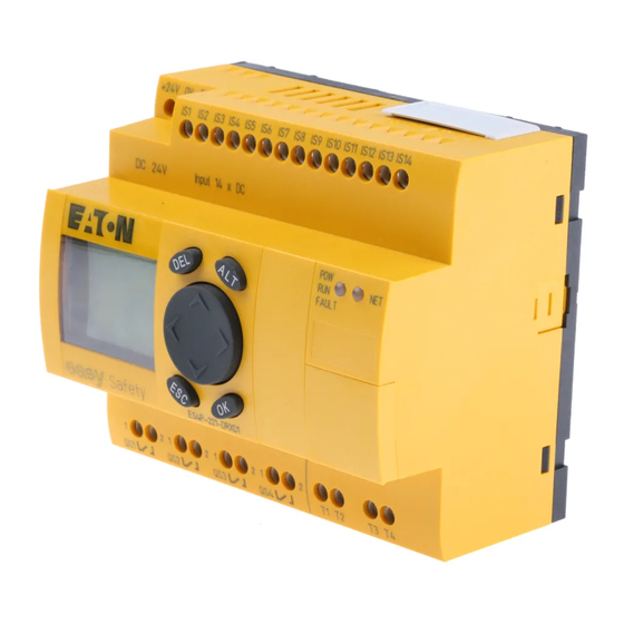
02/16 MN05013001Z EN Device overview Device overview easySafety-Basic device Figure 1: Versions a Supply voltage, a page 44 b Inputs, a page 46 c easyNet-Anschlüsse, a page 59 d Power supply/mode and easyNet LEDs, a page 22. e Serial multi-function interface for memory card, PC connection... -
Page 26: Led Display
02/16 MN05013001Z EN easySafety LED display easySafety is provided with two LEDs on the front (a figure 1 on Page 21): • POW, RUN, FAULT. • NET. RUN, FAULT indicates the status of the power supply, RUN or STOP mode as well as any errors present. -
Page 27: Key To Part Numbers Easysafety
02/16 MN05013001Z EN Device overview Key to part numbers easySafety ES4P - x x x - x x x x x Variant: 1 = 1. Variant LCD display: X = No display, D = with display Analog output: X = no analog output... -
Page 28: Easysafety Operation
02/16 MN05013001Z EN easySafety easySafety operation Keyboard DEL: Delete object in circuit diagram ALT: Special functions in circuit diagram, status display ú í Í Ú Cursor buttons Move cursor Select menu items Change numbers, contacts and values OK: Next menu level, Save your entry... -
Page 29: Status Display For The Easysafety Basic Unit
Status display for the easySafety basic unit After power on, the easySafety device shows the status display of the basic unit. The status display has four lines. If you are operating a local expansion module via the easyLink connection, show the status display of the local expansion module on the display by pressing OK (a page 27). - Page 30 Line 2: System information, diagnostics You can change the content of line 2 (and 3) by pressing ALT. After the initial power up, the easySafety device indicates with P- that the cursor buttons (P buttons) are not active and therefore cannot be used as button inputs in the standard circuit diagram.
-
Page 31: Status Display For The Local Expansion
QR1 QS1..4 STOP Status display for the local expansion Press OK to move from the status display for the easySafety basic unit to the status display for the local expansion unit if the latter is being operated via the easyLink connection. - Page 32 02/16 MN05013001Z EN easySafety Lines 1 and 4: Inputs/outputs Line 1 shows the status of inputs R of the local expansion R 12..5.789..12 and line 4 that of outputs S. In addition line 4 indicates the basic devices operating mode.
-
Page 33: Status Display Additional Information
: easyNET station with Net-ID (1 in this case) : AC expansion functioning correctly : DC expansion functioning correctly : Bus coupling module detected GW flashes: Only easy200-easy detected. I/O expansion not detected. : When the power supply is switched on, the easySafety switches to STOP mode... -
Page 34: Menu Structure
02/16 MN05013001Z EN easySafety Menu structure The easySafety device has two different menu structures, the main menu and the system menu. The main menu provides the most frequently required functions during operation. The system menu is used for entering global device parameters, and can be accessed without entering a password. -
Page 35: Choosing The Main And System Menu
02/16 MN05013001Z EN easySafety operation Choosing the main and system menu IS.2..5..MO 02:00 QS1..4 STOP S .2…6.. password nÆ Current selection SECURITY... S-PARAMETER.. +Æ flashes in the STANDARD... STD PARAMETERS.- STOP å ACTIVATE PW easySafety menu æ SET CLOCK DELETE ALL +æ... -
Page 36: Main Menu
02/16 MN05013001Z EN easySafety Main menu You access the main menu by pressing OK. Main menu Æ SECURITY PROGRAM... parametric Safety STANDARD SAFETY TEST STOP å RUN programming of the circuit diagram TEST SIGNALS... æ safety function block SET CLOCK... -
Page 37: System Menu
02/16 MN05013001Z EN easySafety operation Main menu Æ SECURITY... STANDARD... STOP å RUN a „Setting date and time“, æ SET CLOCK SET CLOCK... Page 584 SUMMER TIME... CARD... INFORMATION... a „Changing between winter/ SET CLOCK summer time (DST)“, Page 585 SUMMER TIME... - Page 38 02/16 MN05013001Z EN easySafety System menu a „Password protection“, Page 567 S-PARAMETER... Æ PROTECTION... PASSWORD... STD PARAMETERS SYSTEM... PASSWORD... ACTIVATE PW æ DELETE ALL SAFETY-ID: PASSWORD... PASSWORD... a „Sealing the safety configuration“, Page 580 PROTECTION... SEAL-SAFETY SEAL SAFETY IS SYSTEM...
- Page 39 02/16 MN05013001Z EN easySafety operation System menu S-PARAMETER... Æ a „Password PROTECTION... STD PASSWORD... protection“, Page 567 STD PARAMETERS SYSTEM... RANGE… ACTIVATE PW MENU LANGUAGE æ DELETE ALL CONFIGURATOR... SAFETY-ID: - a „Protecting special STD PASSWORD... standard areas“, RANGE… Page 572 åÆ...
- Page 40 02/16 MN05013001Z EN easySafety System menu Display NET only in STOP mode S-PARAMETER... Æ PROTECTION... NET... NET PARAMETER.. STD PARAMETERS SYSTEM... LINK... STATIONS... ACTIVATE PW MENU LANGUAGE CONFIGURE æ DELETE ALL CONFIGURATOR... SAFETY-ID: - a „Parameterising and configuring NET stations“, Page 533 NET PARAMETER..
-
Page 41: Selecting Or Toggling Between Menu Items
02/16 MN05013001Z EN easySafety operation Selecting or toggling between menu items Í Ú æ SECURITY... Cursor STANDARD... STOP å RUN æ SET CLOCK... Select or toggle Cursor display â4:23 â4:23 The cursor flashes. HH:MM HH:MM DD.MM DD.MM 05.05 05.05 Ê/... - Page 42 02/16 MN05013001Z EN...
-
Page 43: Installation
02/16 MN05013001Z EN Installation easySafety devices must only be installed and wired up by qualified electricians or other persons familiar with the installation of electrical equipment. Danger of electric shock! Never carry out electrical work on the device while the power supply is switched on. -
Page 44: Mounting
02/16 MN05013001Z EN Installation Mounting Install a easySafety device in an enclosure, switch cabinet or distribution board so that the power feed and terminal connections cannot be touched accidentally during operation. Snap the device onto an IEC EN 60715 top-hat rail or fix it vertically or horizontally in place using fixing brackets. -
Page 45: Mounting On Top-Hat Rail
02/16 MN05013001Z EN Mounting Mounting on top-hat rail Place the easySafety device diagonally on the upper lip of the top-hat rail. Press down lightly on both the device and the top-hat rail until the unit snaps over the lower edge of the top-hat rail. -
Page 46: Screw Mounting
02/16 MN05013001Z EN Installation Screw mounting Fixing brackets that can be inserted on the rear of the easySafety device are required for screw mounting. The fixing brackets are available as an accessory. Figure 5: Inserting a fixing bracket Three fixing brackets are sufficient for a device with four fixing points. -
Page 47: Connecting The Expansion Device
02/16 MN05013001Z EN Connecting the expansion device Connecting the expansion device Figure 7: Mounting and removing expansion modules... -
Page 48: Terminals
Cable protection supply Connect cable protection (F1) of at least 1 A (T) and no more than 4 A (T) to the easySafety device and to the standard expansion device. Caution! The first time it is switched on, the easySafety power supply behaves capacitively, and the inrush current that flows is higher than the nominal input current. -
Page 49: Dc-Basic Device
DC expansion device EASY…-DC-.E L01+ L01- 24 V H Figure 9: Supply voltage to DC expansion unit The DC devices are protected against reverse polarity. However, ensure that the terminals are connected to the correct polarity so that the easySafety devices function properly. -
Page 50: Connecting The Inputs
02/16 MN05013001Z EN Installation Connecting the inputs The easySafety device is provided only with safety outputs. For safety applications, the IS safety inputs must be read in the safety circuit diagram, processed and output exclusively with the QR output (redundant relay output) or one of the QS outputs (safety transistor/relay outputs). -
Page 51: Connecting Easy Dc Digital Inputs
02/16 MN05013001Z EN Connecting the inputs Connecting easy DC digital inputs Use input terminals IS1 to IS14 to connect pushbutton actuators, switches or 3 or 4-wire proximity switches. Given the high residual current, do not use 2-wire proximity switches. Monitored inputs on the basic unit are fed by test signal outputs T1 to T4. - Page 52 ES4P-221-DMXD1 Output 1x Relay / 6A 4x Transistor / 0,5A 4x Test Signal +24V QS1 QS2 QS3 QS4 Figure 11: Example application with basic device easySafety L01 + L01 – E+ E– R11 R12 +24V 24 V H...
-
Page 53: Connecting Outputs
02/16 MN05013001Z EN Connecting outputs Connecting outputs The easySafety device has safety outputs (QR/QS) and test outputs with test signals (T1-T4) exclusively. Test signals are used to detect cross circuits (a section “Test outputs, test signals” on page 153). Connect the test signal outputs T1 to T4 with the inputs in order to be able to detectperipheral faults such as cross- circuits between the signal cables. - Page 54 (a section “Technical data”, page 659). Caution! easySafety may be used in applications up to safety level 3 in continuous operation in accordance with EN 50156 if: • the time between the functional checks on easySafety do not exceed six months.
-
Page 55: Connecting Relay Outputs
02/16 MN05013001Z EN Connecting outputs Connecting relay outputs Caution! Test the relay outputs at least once in 6 months. ES4P-221-DM.. 24 V H 6 A 115 V h 6 A 230 V h 6 A 0 V H, N L1, L2, L3 (115/230 V h) + 24 V H Figure 14: ES4P-221-DM... - Page 56 02/16 MN05013001Z EN Installation EASY6..-..-RE.. (standard expansion device) 24 V H 8 A 10 000 000 115 V h 8 A 230 V h 8 A 1000 W 0 V H, N 10 x 58 W 25 000 F 8 A/B 16 L1, L2, L3 (115/230 V h) + 24 V H Figure 16: EASY6..-..-RE..relay outputs...
-
Page 57: Connecting Transistor Outputs
02 and 10 Danger! The parallel connection of the safety transistor outputs QS1 to QS4 of a easySafety basic unit is not permissible and causes a fault message (fault category B, a page 622). The outputs are switched off as result. - Page 58 02/16 MN05013001Z EN Installation Power the transistor outputs with voltage! If the transistor outputs are not supplied, the easySafety will generate a category B fault, a page 622. This causes all outputs to be switched off. Take into account the time behaviour of the transistor outputs when choosing the actuator that the easySafety device will be actuating.
-
Page 59: Special Requirement For Es4P-221-Dmx
Behaviour in the event of a short-circuit/overload In the event of a short-circuit or overload on a transistor output of a easySafety basic device, all outputs are disconnected. Once you have rectified the fault or malfunction, you can reset the easySafety device by switching the power supply off and on again. - Page 60 02/16 MN05013001Z EN Installation In order to take appropriate precautions for a short-circuit, follow the steps below: Select the right F2 cable protection. Use a power supply unit with enough output current . Selecting the F2 cable protection The cable protection chosen should have a maximum rated operational current I of 3.15 A.
-
Page 61: Connecting Test Signal Outputs
( 4 x 2A ) 8A for 50 ms Connecting test signal outputs The easySafety devices are provided with 4 test signal outputs (T1 to T4). These outputs (T1 to T4) generate periodic test signals that are looped back to an IS... input and evaluated inside the device. - Page 62 02/16 MN05013001Z EN Installation Reset NOT-AUS IS9 IS10 IS11 IS12 IS13 IS14 ea ySafety 4x Test Signal QS2 QS3 QS4 Figure 20: Sample application of test signal outputs in a dual- channel emergency stop circuit 1) Use free-wheel diode suppressors for ES4P-221-DMX..
-
Page 63: Connecting Network Easynet
02/16 MN05013001Z EN Connecting network easyNet Connecting network easyNet is a network for non-safety applications to which a easyNet maximum of 8 nodes can be connected. Any device with a network connection can be an easyNet node. Further information on configuring and commissioning the easyNet is provided in chapter “easyNet network”, page 521. -
Page 64: Prefabricated Network Connection Cables
02/16 MN05013001Z EN Installation The physically first and last stations in the easyNet network must each be terminated with a bus termination resistor. Because the physically first easyNet station has no predecessor, the bus termination resistor is connected to socket 1 here. Accordingly, the bus termination resistor is connected to socket 2 of the last easyNet station. -
Page 65: User-Assembled Network Connection Cables
02/16 MN05013001Z EN Connecting network easyNet User-assembled network connection cables The following components are available for assembling different cable lengths: • Supply cable – Type - EASY-NT-CAB, cable 100 m, 4 x 0.18 mm • Bus connection plug – RJ45 plug, type: EASY-NT-RJ45 (8-pole) •... -
Page 66: Bus Termination Resistor
02/16 MN05013001Z EN Installation Bus termination resistor The physically first and last stations in the easyNET network must each be terminated with a bus termination resistor. • Value: 124 O. • Connection plug : EASY-NT-R. I S1 - 14 R 1 - 12 QS 1 - 4 S 1 - 8 I S1 - 14... -
Page 67: Plugging And Unplugging Network Cables
02/16 MN05013001Z EN Connecting network easyNet Plugging and unplugging network cables Both RJ45 interfaces are visible after the cover plate has been removed. When a cable is plugged in, the mechanical connection must be audible (click) and visible . Before a plug or cable is removed, the mechanical locking feature must be undone , . -
Page 68: Easynet-Topologies
Disadvantage: Each device must be addressed individually with this wiring method: • By downloading the program of the easySafety configuration including the NET-ID via easySoft-Safety (see Help). For this the programming cable must be plugged in locally on each individual device. - Page 69 02/16 MN05013001Z EN Connecting network easyNet Addressing examples Physical Station number "Loop through the T connector and spur location, unit" line Example 1 Example 2 place easy800 easy800 easy...E easy...E ES4P, MFD ES4P, MFD easy800 easy800 easy...E easy...E ES4P, MFD ES4P, MFD easy800 easy800...
-
Page 70: Cable Length With Cross-Sections
02/16 MN05013001Z EN Installation Cable length with cross-sections For correct operation of the easyNet network the cable lengths, cross-sections and cable resistances must match those listed in the following table. Cable length Cable resistance Cross-section mO/m up to 40 F 140 0.13 up to 175 F 70... - Page 71 02/16 MN05013001Z EN Connecting network easyNet Calculating the cable length for a known cable resistance If the resistance of the cable per unit of length is known (resistance per unit length R’ in O/m), the entire cable resistance R must not exceed the following values. R depends on the selected baud rate: Baud rate Cable resistance R...
-
Page 72: Connecting The Serial Multi-Function Interface
= Resistivity of copper, if not otherwise stated 0.018 Omm 12.4 Connecting the serial Each easySafety device is provided on the front with a serial multi-function interface multi-function interface. The interface is factory shipped with a protective cover fitted. Remove this cover carefully. -
Page 73: Connection To A Pc
Remove the cover from the interface and fit the connector plug. Caution! When connecting the programming cable, the easySoft- Safety programming software must be offline. On no account should the programming cable be moved from one easySafety device to another when the connection is online. -
Page 74: Connecting For Point-To-Point Communication
Connecting for point-to-point communication Connect one of the connection cables from table 6 to an MFD-…-CP8 or MFD-…-CP4 and to the serial multi- function interface of the easySafety device. Table 6: Connection cable on an MFD-CP4/CP8… for point-to- point communication... - Page 75 POW-Side Figure 27: Connecting the connector plug: left MFD-CP…, right easySafety The connector marked POW-Side must be plugged into the interface of an MFD. The serial interface only functions if the MFD is providing the power feed required for the...
-
Page 76: Inserting The Memory Card
POW-Side Figure 28: Point-to-point serial interface Inserting the memory card The easySafety devices support the use of memory cards that are fitted into the serial multi-function interface. Each memory card stores a single easySafety configuration. For easySafety devices, use the ES4A-MEM-CARD1 card. -
Page 77: Expanding Inputs/Outputs
Expanding inputs/outputs To increase the number of inputs/outputs, you can connect non-safety expansion devices via the easyLink connection of the easySafety devices. These can then be used for the standard circuit diagram: Danger! Safety-related data must not be transmitted via the easyLink interface. -
Page 78: Local Standard Expansion Device
EASY-LINK-DS EASY6..-..-RE.. ES4P-221-..EASY6..-..-TE.. EASY2… Figure 30: Connecting local expansions with easySafety Danger! The following electrical isolation is implemented between the ES4P-221-…basic device and the expansion device (isolation always in local connection of expansion device): • Basic isolation 400 V AC (+10 %) •... -
Page 79: Remote Standard Expansion
E+ E– = 300/500 V EASY…-AC-…E Figure 31: Connecting remote standard expansion devices to easySafety Terminals E+ and E– of the EASY200-EASY are protected against short-circuits and polarity reversal. Functionality is only ensured if E+ is connected with E+ and E– with E–. - Page 80 02/16 MN05013001Z EN Installation...
-
Page 81: Commissioning
Before startup check whether the power supply, inputs, outputs, the serial interface and the easy-NET connection easyLink are properly connected: • easySafety basic device and 24 VDC expansion unit: – Terminal +24 V: Voltage +24 V – Terminal 0 V: Voltage 0 V. -
Page 82: Setting The Menu Language
02/16 MN05013001Z EN Commissioning Setting the menu When you switch on the easySafety device for the first time, language you will be asked to select the menu language. Í Ú Use the cursor buttons to select the language å ENGLISH required. -
Page 83: Easysafetyoperating Modes
02/16 MN05013001Z EN easySafetyoperating modes easySafetyoperating RUN and STOP and BUSY modes easySafety has the three operating modes RUN, STOP and BUSY. The device switches operating mode BUSY only temporarily when: • a configuration transfer with easySoft-Safety is being performed;... - Page 84 If the easySafety devices without a display do not contain an safety circuit diagram, but this is stored on the memory card, this is loaded automatically after startup. The device will...
-
Page 85: The First Circuit Diagram
In this way you will learn all the rules, quickly enabling you to use a easySafety device for your own projects. Normally you wire the safety circuit diagram following the procedure described here. However, certain rules must be observed here and these are explained fully in section “Rules... - Page 86 As with conventional wiring, you use contacts and relays in the diagram. The easySafety device saves you having to use and wire different components. At the push of a few buttons, the easySafety circuit diagram produces all the wiring required.
-
Page 87: Starting Point: The Status Display
02/16 MN05013001Z EN The first circuit diagram Starting point: the status display When you switch on an easySafety device, it opens the IS....status display immediately. This status display shows the switching state of the inputs and outputs and also indicates... -
Page 88: Switching To The Standard Circuit Diagram
02/16 MN05013001Z EN Commissioning Switching to the standard circuit diagram Switching to the standard circuit diagram Creating a standard circuit diagram for lamp controls, page 86 Testing the standard circuit diagram, page 104 Ú Use the cursor button to change to the STANDARD…. SECURITY…... - Page 89 The first four columns are ÊÊÊÊÊÊÊ-ÊÊÊÊÊÊÊ- contact fields, the fifth column is a coil field. Each line is a ÊÊÊÊÊÊÊ-ÊÊÊÊÊÊÊ- circuit connection. easySafety automatically connects the L: 1 C:1 B:7732 contact to the power supply. Now wire the circuit diagram as described below.
-
Page 90: Creating A Standard Circuit Diagram For Lamp Controls
Creating a standard circuit diagram for lamp controls Testing the standard circuit diagram, page 104 L01+ L01- Figure 33: Lamp controller with relays In the following example, the easySafety device carries out all the wiring and performs the tasks of the circuit diagram shown below. - Page 91 +24V 0V DC 24 V Input 14 x DC ES4P-221-DRXD1 Output 4x Relay / 6A Figure 34: Lamp control with an easySafety device IS01----IS02--...-Ä QS01 L: 1 C:1 B:7944 Figure 35: Standard circuit diagram with inputs IS01 IS02 and output QS01 With this example the switches S1 and S2 are at the input.
- Page 92 02/16 MN05013001Z EN Commissioning From the first contact to the output coil With easySafety devices wire from the input to the output. The first input contact is IS01 Press OK. IS01 easySafety proposes the first contact I at the cursor position.
- Page 93 02/16 MN05013001Z EN The first circuit diagram Wiring A easySafety device displays a small arrow in the standard circuit diagram and in the safety circuit diagram when creating the wiring. Press ALT to activate the wiring arrow cursor and use the Í...
- Page 94 02/16 MN05013001Z EN Commissioning Press OK. --------Ä QS01 Ä The specified coil function and the output relay QS01 correct and do not have to be changed. L: 1 C:15 B:7732 Danger! Device outputs (QS., QR.) used in the standard circuit diagram are not safety outputs, and may only be used for standard outputs.
- Page 95 02/16 MN05013001Z EN The first circuit diagram Saving IS01----IS02--------------------Ä QS01 SAVE … Figure 37: SAVE menu = Visible area Confirm with OK. The circuit diagram is stored. Press the ESC button twice to return to the main menu. Once you have connected pushbutton S1 and S2, you can test your circuit diagram straight away.
-
Page 96: Switching To The Safety Circuit Diagram
As soon as you open a contact or coil field with OK, you must enter the defined M password. Password protection is automatically reactivated if you do not make any changes to the safety configuration of an easySafety device for 30 minutes. - Page 97 02/16 MN05013001Z EN The first circuit diagram Circuit diagram display for the safety circuit diagram The circuit diagram display is currently empty. Start the Ê wiring at the blinking cursor position in the upper left. The display is a precise representation of the standard circuit diagram.a page 85 L: 1 C:1 B:7944 Now try to wire up the following diagram, a section...
-
Page 98: Creating A Safety Circuit Diagram For An Emergency- Stop Circuit
Testing the safety circuit diagram, page 103 The easySafety device is required to monitor the activation of an Emergency-Stop pushbutton and switch off the machine via a load contactor using the ES.. (Emergency Stop, a page 371) safety function block. - Page 99 02/16 MN05013001Z EN The first circuit diagram The functional machine safety of the example shown here complies with architecture of category 1 in accordance with EN ISO 13849-1. +24 V S 1A Reset NOT-AUS gL/gG +24V 0V IS10 DC 24 V Input 14 x DC ES4P-221-DRXD1 Output 4x Relay / 6A...
- Page 100 The first input contact is to be which activates the IS07 emergency-stop function block via function block coil ES..I1. Press OK. IS01 easySafety proposes the first contact at the cursor IS01 position. flashes and can be changed, for example, to a QR01 L: 1 C:1 B:7704 Í...
- Page 101 02/16 MN05013001Z EN The first circuit diagram Wiring A easySafety device displays a small arrow l, the same tool as already in the standard circuit diagram, the wiring arrow (a page 89). 1rd circuit diagram line Press ALT to activate the wiring arrow.
- Page 102 >DT 3.0s left). In this way, this function block is stored in the easySafety device which simplifies its further use. Set the parameters for the ES..safety function block in this example in the function block editor. The first parameter NEN that can be changed flashes in Entry mode.
- Page 103 Ú Press the cursor button up to the function block coil ES01I1 in the coil field. As this function block is already in the easySafety device you --------Ä ES01I1 can simply move to the function block input. --------Ä ES01I1 í...
- Page 104 This is used as a contact of the function block output - contact ES01..QS. This is associated directly with the safety device output QS. Press OK. easySafety enables the first contact at the cursor IS01 position and causes the contact name to flash.
- Page 105 Figure 41: SAVE menu of the safety circuit diagram = Visible area Press the OK button. The safety circuit diagram is stored. Press the ESC button twice to return to the main menu. easySafety cannot be started without a safety circuit diagram entered.
- Page 106 Commissioning Testing the rules of the safety circuit diagram (plausibility check) Requirement: the easySafety must be in STOP mode. Use the SAFETY TEST function to test whether your circuit diagram complies with the rules for safety circuit diagrams (a section “Rules in the safety circuit diagram” on page 341).
-
Page 107: Testing The Safety Circuit Diagram
02/16 MN05013001Z EN The first circuit diagram Testing the safety circuit diagram Switching to the safety circuit diagram, page 92 Creating a safety circuit diagram for an emergency-stop circuit, page 94 Testing the safety circuit diagram Once you have connected the Emergency-Stop button and the Reset button, you can test your circuit diagram. -
Page 108: Testing The Standard Circuit Diagram
02/16 MN05013001Z EN Commissioning Testing the standard circuit diagram Requirement: a safety circuit diagram has already been created a page 92. Switching to the standard circuit diagram, page 84 Creating a standard circuit diagram for lamp controls, page 86 Testing the standard circuit diagram Switch back to the main menu and select the STOP RUN PROGRAM... - Page 109 The first circuit diagram Test using the power flow display A easySafety device enables you to check the power flow in RUN mode. While the device is processing the circuit diagram in RUN mode, you can use the integrated power flow display to check this.
- Page 110 02/16 MN05013001Z EN Commissioning Power flow display with Zoom function With the easySafety device you can check the following at a glance: • All four contacts plus one coil in series • 3 Rungs/Current paths Change to the circuit diagram display and press the ALT button.
-
Page 111: Deleting The Standard Circuit Diagram
= Visible area Deleting the standard circuit diagram Switch the easySafety device to STOP mode. In order to expand, delete or modify the standard circuit diagram, easySafety must be in STOP mode. Choose STANDARD -> PROGRAM… to switch from the main menu to the appropriate menu level. - Page 112 02/16 MN05013001Z EN...
-
Page 113: Wiring With Easysafety
02/16 MN05013001Z EN Wiring with easySafety This chapter describes the entire range of functions of an easySafety device. easySafety operation Buttons for editing circuit diagrams and function blocks Delete rung, contact, relay or empty rung in the circuit diagram Toggle between n/o and n/c contact... -
Page 114: Operation
IS01 change a value at the cursor position. Press ESC in Entry mode to restore easySafety to the last changes of an entry. Press ALT to switch to Connect mode for wiring contacts and relays. Press ALT again to return to Move. -
Page 115: Circuit Diagram Elements
Contacts can, for example, be the inputs of the easySafety device or outputs of safety function blocks. Coils can, for example, be outputs of the basic unit or inputs of safety function blocks. Special measures are implemented to ensure that the safety function blocks operate error-free. - Page 116 02/16 MN05013001Z EN Wiring with easySafety Non-safety-relevant tasks Certain inputs/outputs of safety function blocks can be connected in the safety circuit diagram or also in the standard circuit diagram. The device safety inputs can also be read and processed in the standard circuit diagram. The result is output via safety outputs which however, CANNOT be used in the safety circuit diagram.
-
Page 117: Function Blocks
02/16 MN05013001Z EN Circuit diagram elements The easySafety control relay can be connected locally or via easyNet with a non-safety I/O expansion device. These non- safety I/Os are only read, processed and written by the standard circuit diagram. Further information on expansion options is provided in chapter “Expanding an easySafety device”... -
Page 118: Contacts
Coils can have seven different coil functions which is explained in greater detail on page 145. A easySafety device is provided with different types of relays and function blocks which can be wired in a circuit diagram via their coils (inputs). -
Page 119: Markers
643. Markers The term “marker” generally refers to the standard marker bit (M). easySafety devices also process safety marker bits (MS), marker bytes (MB), marker words (MW) and marker double words (MD). Standard markers are used in the appropriate format for the intermediate storage of data. - Page 120 02/16 MN05013001Z EN Wiring with easySafety Table 9: Composition of the standard markers Bit (M) 96-89 88-81 80-73 72-65 64-57 56-49 48-41 40-33 32-25 24-17 16-9 8-1 Byte (MB) Word (MW) D-Word (MD) Byte (MB) Word (MW) D-Word (MD) Byte (MB)
- Page 121 02/16 MN05013001Z EN Circuit diagram elements Word (MW) D-Word (MD) Word (MW) D-Word (MD) Word (MW) D-Word (MD) Word (MW) D-Word (MD) Word (MW) D-Word (MD) Word (MW) D-Word (MD) Word (MW) D-Word (MD) Word (MW) D-Word (MD) D-Word (MD) D-Word (MD) …...
- Page 122 02/16 MN05013001Z EN Wiring with easySafety Retentive standard markers You can declare a freely definable contiguous range of marker bytes within the range MB01-MB96 as retentive. The table 9 shows how together with these marker bytes MB01- MB96, also marker words MW01-48 and marker double words MD01-24 can be declared as retentive.
- Page 123 02/16 MN05013001Z EN Circuit diagram elements Number formats The easySafety device processes calculations with a signed 31-bit value. The value range is: –2147483648 to +2147483647 With a 31-bit value, the 32nd value is the sign bit. Bit 32 = status 0 -> positive number.
-
Page 124: Circuit Diagram Display
02/16 MN05013001Z EN Wiring with easySafety Circuit diagram display You wire contacts and coils of relays in the easySafety circuit diagram from left to right, from the contact to the coil. The standard circuit diagram is entered in an invisible wiring grid with contact fields, coil fields and rungs, and wired together with connections. - Page 125 The number of free bytes is indicated. easySafety circuit diagram display For greater legibility the circuit diagram of the easySafety IS01----IS02--u device shows two contacts or one contact plus coil in a row QS01----HY01Q1k on each rung.
-
Page 126: Transfer From And To The Memory Card
Configurations are transferred via the serial multi-function memory card interface. There are two possibilities: • From or to a easySafety memory card, a page 124. • Via the programming cable from or to the COM serial PC interface and thus from or to the configuration software easySoft-Safety, a page 129 or in the Online Help. -
Page 127: Transfer From/To A Device Without Display
02/16 MN05013001Z EN Transfer from and to the memory card On the memory card you can save: • the configuration. • all parameter sets of the configuration. • all display texts with functions. • the safety system settings: – Master and safety password. –... -
Page 128: Loading And Saving With A Memory Card
02/16 MN05013001Z EN Wiring with easySafety Loading and saving with a memory card The loading of a configuration from the memory card and the saving on the card is carried out via the CARD menu. The following overview shows how you operate with and without password. - Page 129 02/16 MN05013001Z EN Transfer from and to the memory card Saving a configuration on the memory card (DEVICE -> CARD) In devices without a display and keypad, transferring a configuration to the memory card is not possible. Requirements: • The device in the STOP. •...
- Page 130 • 14 IS, 4 QS (relay outputs) or • 14 IS, 4 QS (transistor outputs) and 1 QR (relay output). The configuration to be loaded on an easySafety must have the same I/O profile as the target device; otherwise the easySafety device will reject the transfer.
- Page 131 02/16 MN05013001Z EN Transfer from and to the memory card CARD -> DEVICE Empty card? Contains faulty configuration? Display PROG. INVALID I/O profile identical? Display IO PROFILE DOES NOT MATCH Assign master password? Entering the master password REPLACE? CARD menu is left without any Cancel Configuration is transferred to operation...
-
Page 132: Deleting A Circuit Diagram On The Card
DELETE CARD transferred to the device in addition to the permanently LANGUAGES->CARD installed menu language "English" from easySafety. æ CARD->LANGUAGES These variable menu languages can be stored together with the safety configuration on a card. -
Page 133: Loading And Saving With Easysoft-Safety
(online status). A easySafety device cannot exchange data with the PC if it has been switched to the circuit diagram display. Further information with detailed instructions on the easySoft-Safety configuration software is provided in the online help. - Page 134 In order to identify modifications to the safety configuration that were carried out on the device, the version number is always reset to 0000. If there is a transfer problem, the easySafety device shows CONFIG. INVALID the CONFIG. INVALID message.
-
Page 135: Working With Contacts And Relays
Working with contacts Switches, pushbuttons and relays from a conventional and relays hardwired circuit diagram are wired in the easySafety circuit diagram via input contacts and relay coils. easySafety safety circuit diagram The following example of a safety circuit diagram is the page 94 in section “The first circuit... -
Page 136: Entering And Changing Contacts And Coils
The following describes how you wire the different contacts and coils of different relay types or function blocks (inputs) in the circuit diagram. Contacts You choose an input contact in the easySafety device by IS02 means of the contact name and the contact number. Contact name... - Page 137 02/16 MN05013001Z EN Working with contacts and relays Coils With a relay coil or a function block, you choose the coil function, coil name, coil number as well as the function block coil. With coils of an easyNet station, choose the address (NET ID) in front of the coil name.
- Page 138 OK. ÍÚ to modify the value of the position. The easySafety device closes entry mode as soon as you ú í leave a contact or coil field with or OK.
- Page 139 02/16 MN05013001Z EN Working with contacts and relays In the contact field In the coil field Ä QR01 change change IS01 IS02 S QS04 Ä IS01 IS02 QR01 S QR01 QS01 QS04 1 x í + ú Í Ú ä OK + 1 x Í...
- Page 140 02/16 MN05013001Z EN Wiring with easySafety Deleting contacts and coils ú í ÍÚ to move the cursor to a contact or coil field. Press DEL. The contact or the coil will be deleted, together with any connections. Changing make contacts to break contacts You can define each contact in the circuit diagram as a make or break contact.
-
Page 141: Creating Or Changing Connections
The easySafety device closes the mode automatically as soon as you have moved the arrow to an occupied contact or coil field. In a rung, the easySafety device connects contacts and the connection to the relay coil automatically if no empty fields are between them. - Page 142 Press ALT to switch to Connect mode. Press DEL. The easySafety device deletes a connection branch. Closed adjacent connections will be retained. Close the delete operation with ALT or by moving the cursor...
-
Page 143: Adding Or Deleting Rungs
The circuit diagram display shows three of the 256 rungs at the same time. Rungs outside of the display, including empty rungs, are scrolled by easySafety automatically in the circuit diagram display if you move the cursor beyond the top or bottom of the display. -
Page 144: Aborting Circuit Diagram Entry
02/16 MN05013001Z EN Wiring with easySafety Aborting circuit diagram entry Press ESC to leave the circuit diagram entry without IS01----IS02--u saving. ÍÚ QS01----HY01Q1k Use the cursor buttons to select the CANCEL menu. Æ æ Press OK. CANCEL The circuit diagram is closed without saving. -
Page 145: Got To A Rung
You can use the "GO TO" function to jump to any rung, up to the last wired rung. Deleting rungs The easySafety device only removes empty rungs (without contacts or coils). Delete all contacts and coils from the rung. Position the cursor on the first contact field of the empty rung. -
Page 146: Switching With The Cursor Buttons
02/16 MN05013001Z EN Wiring with easySafety Switching with the cursor buttons The easySafety device allows the four cursor buttons also to be used as permanently wired inputs in the standard circuit diagram. The buttons are wired in the standard circuit diagram as contacts . -
Page 147: Checking The Circuit Diagram
IS02--u------------------------S QS01 IS03--k Figure 56: Parallel connection Switch the easySafety to RUN via the main menu. Return to the circuit diagram display. You are now unable to edit the circuit diagram. If you change to the circuit diagram display but cannot change a circuit diagram, first check whether the easySafety device is in STOP mode. - Page 148 02/16 MN05013001Z EN Wiring with easySafety IS02==š=========================S QS04 IS03==– L:001 C:1 Figure 57: Power flow display In the power flow display, energized connections are thicker than non-energized connections. You can follow energized connections across all rungs by scrolling the display up and down.
-
Page 149: Coil Functions
Working with contacts and relays Coil functions You can set the coil function to determine the switching behaviour of relay coils. The following coil functions are assigned to all coils: Table 10: Coil function easySafety Coil function Example display Page Ä ÄQS01,ÄD02,ÄS04,Ä:01,ÄM07,.. - Page 150 02/16 MN05013001Z EN Wiring with easySafety Ä Coil with contactor function The output signal follows immediately after the input signal and the relay acts as a contactor. Figure 58: Contactor function signal diagram ä Impulse relay The relay coil switches whenever the input signal changes from 0 to 1.
- Page 151 02/16 MN05013001Z EN Working with contacts and relays and Reset coil function The Set and Reset coil functions are normally used in pairs. The relay picks up when the coil is set (A) and remains in this state until it is reset (B) by the coil function. The supply voltage is switched off (C), the coil does not have a retentive effect.
- Page 152 02/16 MN05013001Z EN Wiring with easySafety Å Coil negation (inverse contactor function) The output signal follows the inverted input signal, the relay works like a contactor with negated contacts. If the coil is set to 1, the coil will switch its make contacts to 0.
- Page 153 02/16 MN05013001Z EN Working with contacts and relays è Falling edge evaluation (cycle pulse) This function is used if the coil is only meant to switch on a falling edge. When the coil status drops out from 1 to 0, the coil switches its make contacts to 1 for one cycle.
-
Page 154: Jumps
Details on the use of jumps in the standard function block diagram are provided in section “LB, jump label” on page 272 and in section “JC, conditional jump” on page 268. The easySafety device allows the use of up to 16 jumps. Circuit diagram symbols for jumps Contact N/O contact... - Page 155 The jump contact location is always 1. Backward jumps cannot be executed due to the way in which easySafety works. If the jump label does not come after the jump coil, the jump will be made to the end of the circuit diagram.
- Page 156 02/16 MN05013001Z EN Wiring with easySafety Example A selector switch is used to select two different sequences. • Sequence 1: Switch on motor 1 immediately. • Sequence 2: Activate barrier 2, wait time, then switch on motor 1. Contacts and relays used: •...
-
Page 157: Test Outputs, Test Signals
Working with contacts and relays Test outputs, test signals easySafety is provided with 4 outputs with test signals T1 to T4 for detecting cross-circuits at the device inputs or in the external wiring. In the following example, the emergency-stop switch S1 is connected to test outputs T3 and T4. - Page 158 02/16 MN05013001Z EN Wiring with easySafety When using a test output for several inputs ensure that no hazardous faults can occur. Æ To do this press OK to open the main menu and enter SECURITY... SECURITY... DEFAULT... STOP å RUN æ...
-
Page 159: Working With Function Blocks
The following applies to function blocks: Current actual values are deleted when you switch off the power supply or switch easySafety to STOP mode. Exception: retentive data keeps its state (a section “Retention”, page 597). The most recent actual values are transferred to the operands every cycle. - Page 160 “Deleting function blocks”, page 170. Caution! RUN mode: easySafety processes the function blocks after the circuit diagram has been run through. This takes the last status of the coils into account.
-
Page 161: Adding Function Blocks To The Circuit Diagram For The First Time
ÍÚú í Use the buttons to move the cursor to a free contact or coil field. Press OK so that the easySafety device switches to entry mode. 1 C:1 B:7520 When editing the safety circuit diagram you have to enter the M password before this change if the device has not been unlocked (a page 571). -
Page 162: Setting Function Block Parameters
02/16 MN05013001Z EN Wiring with easySafety Setting function block parameters Safety function blocks with which you can implement your safety functions are always part of the safety circuit diagram. Unlike standard function blocks, the parameters are set from the safety circuit diagram instead of in a special function block editor. - Page 163 02/16 MN05013001Z EN Working with function blocks Parameterise function block (FB) Standard Safety function block (Si-FB) function block (Std FB) Safety or standard FB? Main menu: Main menu: SECURITY -> PROGRAM STANDARD -> PROGRAM -> CIRCUIT DIAGRAM Parameter dialog, Edit standard circuit Parameter dialog for Edit safety circuit a page 160...
- Page 164 02/16 MN05013001Z EN Wiring with easySafety Parameter assignment from the safety circuit diagram The parameter dialog for the safety function block is opened. The figure on the left shows a parameter dialog with the TS01 example of the safety function block TS, Safety timing relay.
- Page 165 Press ESC in order to save the circuit diagram with the newly added standard function block. Answer the subsequent SAVE prompt with OK. The standard circuit diagram is saved and the easySafety device changes to the next higher menu level.
- Page 166 02/16 MN05013001Z EN Wiring with easySafety Parameter setting in the function block editor (standard function blocks) Open the function block editor via the FUNCTION RELAYS menu. Then first enter the function block list in which the standard function blocks used are listed.
- Page 167 02/16 MN05013001Z EN Working with function blocks Unit/special function Function Parameter display (+ appears/ Function block number – does not appear) Function block name T 01 X? M:S + >I1 20:30 Variable, operand for Function block inputs >I2 inputs Function block outputs QV>...
- Page 168 You should therefore take care to exclude such situations, as the easySafety device cannot foresee these when the parameters are assigned. If, for example, you have assigned the QV output of the AR...
- Page 169 02/16 MN05013001Z EN Working with function blocks Assigning operands at the output of a safety function block The actual value ...QV of a safety function block is normally used to output the actual values of monitoring times or frequencies. You can assign the ...QV actual value output of a safety function block to the MD, MW, MB markers or to the input of certain standard function blocks in the standard function block diagram.
-
Page 170: Changing Function Block Parameters
RUN mode. With safety function blocks, parameters can only be changed via the safety circuit diagram and only then if the easySafety device is in STOP mode. The procedures for changing parameters of a safety or standard function block are... - Page 171 02/16 MN05013001Z EN Working with function blocks Changing standard function block parameters Parameters of the standard function blocks that you use in the standard circuit diagram can be changed with the following accesses: • Access 1 - FUNCTION RELAYS, STOP mode All parameters can be set or deleted via STANDARD ->...
- Page 172 02/16 MN05013001Z EN Wiring with easySafety Open the function block list via STANDARD -> PROGRAM -> FUNCTION RELAYS. First enter the function block list. All standard function blocks used in the standard circuit diagram are displayed here. Í Ú T 03 Ü...
- Page 173 PARAMETERS Requirements for parameter assignment via STANDARD - >PARAMETERS: • The easySafety device is in RUN mode. • The standard function block is used in the standard circuit diagram or function block. • Access to the parameter set is enabled, indicated by the +/ - character at the top right of the display.
-
Page 174: Deleting Function Blocks
02/16 MN05013001Z EN Wiring with easySafety Deleting function blocks Requirement: The easySafety device must be in STOP mode. Move the cursor in the circuit diagram to all the contact fields and the coil field in which the function block to be deleted is used and press DEL each time. -
Page 175: Checking Function Blocks
02/16 MN05013001Z EN Working with function blocks Checking function blocks Requirement for the check: The easySafety device must be in RUN mode. Checking safety function blocks You can check safety function blocks using the safety circuit diagram. In the circuit diagram, position the cursor on the required safety function block in a contact or coil field. - Page 176 02/16 MN05013001Z EN Wiring with easySafety Depending on the display selected the standard function AR01 block is shown with the actual values and the result, or with >I1 20056 the set operands and constants. >I2 1095 Press the ALT button if you wish to switch from operand to QV>...
-
Page 177: Standard Function Blocks
02/16 MN05013001Z EN Standard function blocks Standard function blocks are used to implement NON- safety-related tasks in the controller. They are therefore only used in the standard circuit diagram. Danger! Device outputs QR and QS that are set by the standard circuit diagram are not safety outputs and must only be used for standard tasks. - Page 178 An analog value comparator or threshold value switch is comparator/threshold used, for example, to compare marker contents and switch value switch when defined threshold values are reached. easySafety allows the use of up to 16 analog value comparators/threshold switches. Function block A... Analogue value >I1...
- Page 179 02/16 MN05013001Z EN A, analog value comparator/ threshold value switch Wiring of the function block You wire the analog value comparator function block in the standard circuit diagram with its contacts. Example of a function block for comparing analog values: M 01----A 01Q1-----------------Ä...
- Page 180 02/16 MN05013001Z EN Standard function blocks Operating mode This parameter defines which comparison result is to be used to close function block contact Q1. Parameters Function, parameterisation in the function block >I1 greater than >I2 >I1 equal to >I2 >I1 less than >I2 The factory setting of this parameter is LT.
- Page 181 02/16 MN05013001Z EN A, analog value comparator/ threshold value switch Parameters Function Gain factor 1: -2147483648 - +2147483647 >F1 Gain factor 2: -2147483648 - +2147483647 >F2 You can use the offset input >OS to move the zero point of the function block input >I1. Parameters Function Offset: -2147483648 - +2147483647...
- Page 182 02/16 MN05013001Z EN Standard function blocks Contacts The contacts of the function block are evaluated in the standard circuit diagram. A closed contact indicates: Parameters Function Comparison value reached A ..Q1 Value range exceeded A ..CY Memory requirement The analog value comparator function block requires 68 bytes of memory plus 4 bytes per constant at the function block inputs.
- Page 183 02/16 MN05013001Z EN A, analog value comparator/ threshold value switch Figure 72: Signal diagram for analog value comparator 1: Actual value on >I1 2: Setpoint value on >I2 3: Hysteresis on >HY 4: Switch contact (make) 5: Offset for value >I1 6: Actual value plus offset •...
- Page 184 02/16 MN05013001Z EN Standard function blocks • Comparison >I1 equals >I2 The contact switches on: – If I1 is equal to I2, i.e. the actual value is equal to the setpoint value. – If I1 is equal to I2, i.e. the actual value is equal to the setpoint value.
-
Page 185: A, Analog Value Comparator/Threshold Value Switch174
AR, arithmetic function The arithmetic function block is used for all four basic block calculations: • add • subtract • multiply • divide. easySafety allows the use of up to 16 arithmetic function blocks. Function block AR... ARithmetic >I1 >I2 QV>... - Page 186 02/16 MN05013001Z EN Standard function blocks Wiring of the function block An arithmetic function block does not require an enable or start signal and is therefore not wired in a coil field of the standard circuit diagram. The function block is provided with the two Boolean outputs mentioned above for controlling the calculation result that you wire as contacts in the standard circuit diagram.
- Page 187 02/16 MN05013001Z EN AR, arithmetic function block Operating mode This parameter is used to set the arithmetic operation required. Parameters Function, parameterisation in the function block Addition of summand value >I1 plus summand >I2 Subtraction of minuend >I1 minus subtrahend >I2 Multiplication of factor >I1 by factor >I2 Division of dividend >I1 by divisor >I2...
- Page 188 02/16 MN05013001Z EN Standard function blocks • Constant. • Markers MD, MW, MB. • Output QV> of a different function block. … Output The output provides the calculation result as an integer. Parameters Function, parameterisation in the function block Value: -2147483648 - +2147483647 QV>...
- Page 189 02/16 MN05013001Z EN AR, arithmetic function block The following examples illustrate the functions of the function block for every arithmetic operation: Addition examples • 42 + 1000 = 1042 • 2147483647 + 1 = Last valid value before this arithmetic operation, due to overflow (CARRY) AR..CY = Status 1 •...
-
Page 190: Bc, Data Block Comparator
For this you define the number of bytes to be compared. The comparison is carried out in byte format for marker types MB, MW and MD. easySafety allows the use of up to 16 data block comparators. Function block BC... - Page 191 02/16 MN05013001Z EN BC, data block comparator Wiring of the function block You wire the function block in the standard circuit diagram with its enable coil and its contacts. Example of a function block for comparing data blocks: IS05--------------------------Ä BC11EN Figure 76: Wiring the enable coil BC11E1o BC11E2s...
- Page 192 02/16 MN05013001Z EN Standard function blocks Parameter display The display of the parameters during operation can be disabled. Further information can be found in section “Parameter assignment from the standard circuit diagram” on page 161. Parameters Function Parameters are displayed Parameters are not displayed This parameter is factory set to +.
- Page 193 02/16 MN05013001Z EN BC, data block comparator Specifying the marker range Marker ranges can be specified with or without an offset. Marker range without offset If MB, MW or MD markers are specified at both >I1 and >I1 the number of the markers is the start of comparison range. Marker range with offset If you wish to work with an offset, specify one of the following variables at function block input >I1 or >I2:...
- Page 194 02/16 MN05013001Z EN Standard function blocks Coil The coil of the function block is used in the standard circuit diagram. Parameters Function Selective activation of the function block BC..EN Contacts The contacts of the function block are evaluated in the standard circuit diagram.
- Page 195 02/16 MN05013001Z EN BC, data block comparator Example 1: Comparison of marker blocks, direct definition of marker ranges Two marker blocks are to be compared. Block 1 starts at MB10, Block 2 starts at MB40. Each block is 10 bytes long. •...
- Page 196 02/16 MN05013001Z EN Standard function blocks Example 2:Comparison of marker blocks, definition of a marker range with offset Two marker blocks are to be compared. Block 1 starts at MB15, Block 2 starts at MB65. Each block is 4 bytes long. •...
- Page 197 02/16 MN05013001Z EN BC, data block comparator Example 3: Comparison of marker blocks, definition of a marker range in a different format. Two marker blocks are to be compared. Block 1 starts at MB60, Block 2 starts at MD80. Each block is 6 bytes long. •...
- Page 198 02/16 MN05013001Z EN Standard function blocks Example 4:Comparison of marker blocks, range violation error. Two marker blocks are to be compared. Block 1 starts at MD60, Block 2 starts at MD90. Each block is 30 bytes long. • Parameters of function block BC01: –...
- Page 199 02/16 MN05013001Z EN BC, data block comparator Example 6: Comparison of marker blocks, invalid offset error. Two marker blocks are to be compared. Block 1 starts at MW40, block 2 at MW54. The block length is determined by the value of counter C 01QV. •...
-
Page 200: Bt, Data Block Transfer
(data initialisation). The following marker types can be transferred and overwritten: • MB. • MW. • MD. easySafety allows the use of up to 16 data block transfer function blocks. Function block BT... Block Transmitter >I1... - Page 201 02/16 MN05013001Z EN BT, data block transfer Wiring of the function block You wire the function block in the standard circuit diagram with its trigger coil and its contacts. Example of a block transfer function block: IS05--------------------------Ä BT07T_ Figure 79: Wiring the trigger coil The trigger coil is connected to a device input.
- Page 202 02/16 MN05013001Z EN Standard function blocks Operating mode The mode setting defines whether marker ranges are to be copied or initialised. Parameters Function Initialise marker ranges Copy marker ranges This parameter is factory set to INI. Parameter display The display of the parameters during operation can be disabled.
- Page 203 02/16 MN05013001Z EN BT, data block transfer • Constant. • Markers MD, MW, MB. • Output QV> of a different function block. … Specifying the marker range Marker ranges can be specified with or without an offset. Marker range without offset If MB, MW or MD markers are specified at both >I1 and >I2 the number of the markers is the start of comparison range.
- Page 204 02/16 MN05013001Z EN Standard function blocks Contacts The contacts of the function block are evaluated in the standard circuit diagram. A closed contact indicates: Parameters Function Exceeding the source or destination range BT..E1 Overlapping of source and destination range BT..E2 Invalid offset BT..E3 Memory requirement...
- Page 205 02/16 MN05013001Z EN BT, data block transfer Example 1: Initialising marker blocks, direct definition marker ranges The value of marker byte 10 is to be transferred to marker bytes 20 to 29. • Parameters of function block BT01: – Source range: >I1 MB10 –...
- Page 206 02/16 MN05013001Z EN Standard function blocks Example 2: Initialisation of marker blocks, definition of a range with offset The content of marker byte MB15 is to be transferred to marker bytes MB65 to MB68. • Parameters of function block BT01: –...
- Page 207 02/16 MN05013001Z EN BT, data block transfer Example 3: Initialisation of marker blocks, transfer of a range to a different format. The value of marker byte MB60 is to be transferred to MD80 and MD81. • Parameters of function block BT01: –...
- Page 208 02/16 MN05013001Z EN Standard function blocks After a rising edge from 0 to 1 at coil BT01T_ the value 757935405 is present in the marker double words MD80 and MD81. Example 4: Transfer of marker byte, destination range violation error. The value of marker byte MB96 is to be transferred to MD93, MD94, MD95 and MD96.
- Page 209 02/16 MN05013001Z EN BT, data block transfer CPY mode, copy marker ranges There is one source range and one destination range. The source range is specified at >I1. The destination range is specified at >I2. The length of the source and destination range is specified by the number of bytes at the >NO input.
- Page 210 02/16 MN05013001Z EN Standard function blocks Source Value of Destina- Value of desti- range source marker tion nation marker range range range (decimal) (decimal) MB17 MB27 MB18 MB28 MB19 MB29 After a rising edge from 0 to 1 at coil BT01T_ the content of MB10 to MB19 is copied to the marker bytes MB20 to MB29.
- Page 211 02/16 MN05013001Z EN BT, data block transfer Example 3: Copying of marker blocks, definition of a range in a different format Marker range MD60 to MD62 is to be copied to MW40 to MW45. • Parameters of function block BT01: –...
- Page 212 02/16 MN05013001Z EN Standard function blocks Example 4: Copying of marker bytes, destination range violation error Marker range MB81 to MB96 is to be transferred to MD93 to MD96. The length is 16 bytes. • Parameters of function block BT01: –...
- Page 213 02/16 MN05013001Z EN BT, data block transfer Example 6: Copying of marker bytes, invalid offset error. The value of marker word MW40 is to be copied to MW54 and subsequent marker words. The block length is specified by the value of the counter C 01QV. •...
-
Page 214: Bv, Boolean Operation
The function block enables the values to be combined in Boolean (logic) operations. It has the following functions: • Masking out of particular bits from values, • Bit pattern recognition, • Bit pattern modification. easySafety allows the use of up to 16 Boolean operations. Function block BV... >I1 >I2 QV>... - Page 215 02/16 MN05013001Z EN BV, Boolean operation Parameters When using the function block in the circuit diagram for the BV01 AND first time, use OK to automatically enter the general display >I1 of function block parameters, as shown in the figure on the >I2 left.
- Page 216 02/16 MN05013001Z EN Standard function blocks Parameter display The display of the parameters during operation can be disabled. Further information can be found in section “Parameter assignment from the standard circuit diagram” on page 161. Parameters Function Parameters are displayed Parameters are not displayed This parameter is factory set to +.
- Page 217 02/16 MN05013001Z EN BV, Boolean operation Contact The contact of the function block is evaluated in the standard circuit diagram. A closed contact indicates: Parameters Function, parameterisation in the function block Result at output QV> is zero BV..ZE Memory requirement of the function block The Boolean operation function block requires 40 bytes of memory plus 4 bytes per constant at the function block inputs.
- Page 218 02/16 MN05013001Z EN Standard function blocks XOR Boolean operation Value >I1: 13219 = 0011001110100011 Value >I2: 57193 = 1101111101101001 Result QV>: 60618 = 1110110011001010 NOT Boolean operation Value >I1: 13219 00000000000000000011001110100011 Value >I2: deleted Result QV>: -13220 11111111111111111100110001011100 The NOT sequence operates according to the following rules: >I1, positive value Subtract value of >I1 and 1: –|>I1| –...
-
Page 219: C, Counter Relay
You can set a lower and higher limit setpoint as comparison values for the counter relay function block, as well as a start value. easySafety allows the use of up to 16 counter relays. Square wave count pulses are required to ensure a 1:1 mark to space ratio. - Page 220 02/16 MN05013001Z EN Standard function blocks Function block C... Counter >SH >SL >SV QV> Figure 83: Counter relay function block a Coil C..C_: Count coil, starts function block counting with every rising edge. b Coil C..RE: Resets the counter relay to zero. c Coil C..D_: Sets the count direction: Closed: Up counting, Open: Down counting.
- Page 221 02/16 MN05013001Z EN C, counter relay k Contact C..CY: Closes if the value range is exceeded for a cycle per rising count edge. If it is closed, the function block retains the value of the last valid operation. l Actual value output C..QV: Outputs the current actual value. Wiring of the function block You wire the function block in the standard circuit diagram with its coils and its contacts.
- Page 222 02/16 MN05013001Z EN Standard function blocks Parameters When using the function block in the circuit diagram for the C 16 first time, use OK to automatically enter the general display >SH of function block parameters, as shown in the figure on the >SL left.
- Page 223 02/16 MN05013001Z EN C, counter relay Inputs The upper and lower limit setpoints are set at function block inputs >SH and >SL respectively. The start value is used to cause the function block to count from a specified offset value. Parameters Function Upper setpoint: -2147483648 - +2147483647...
- Page 224 When is started in RUN mode, the counter relay continues with the retentively stored actual value. If easySafety is started in RUN mode, the timing relay operates with the retentively saved actual value.
- Page 225 02/16 MN05013001Z EN C, counter relay Operation of the function block ....Figure 86: Signal diagram of counter relay...
- Page 226 02/16 MN05013001Z EN Standard function blocks Legends to figure 86: 1: Counter coil C..C_ 2: Upper setpoint value >SH 3: Start value >SV. 4: Lower setpoint value >SL. 5: Counting direction, coil C..D_ 6: Transfer start value, coil C..SE. 7: Reset coil C..RE 8: Contact (make contact) C..OF: Upper limit setpoint reached, exceeded 9: Contact (make contact) C..FB lower limit setpoint reached,...
-
Page 227: Cp, Comparator
This function block is used to compare variables and/or constants with each other. The following comparisons are possible: • >I1 greater than >I2 • >I1 equal to >I2 • >I1 less than >I2 easySafety allows the use of up to 16 comparators. Function block CP... ComParator >I1 >I2 Figure 87: Comparator function block a Inputs CP..I1 and CP..I2: The value at input I1 is compared with... - Page 228 02/16 MN05013001Z EN Standard function blocks The contact of the function block is sent to markers. Parameters When using the function block in the circuit diagram for the CP12 first time, use OK to automatically enter the general display >I1 of function block parameters, as shown in the figure on the >I2 left.
- Page 229 02/16 MN05013001Z EN CP, comparator The function block inputs I1 and I2 can have the following operands: • Constant. • Markers MD, MW, MB. • Output QV> of a different function block. … Contacts The contacts of the function block are evaluated in the standard circuit diagram.
-
Page 230: D, Text Display
The SP function block can be used to output the text and the variables via the multi-function interface to a peripheral device such as a terminal. easySafety allows the use of up to 16 function blocks for text display. The easySoft-Safety configuration software is used for editing the individual text lines in the Parameters tab. - Page 231 02/16 MN05013001Z EN D, text display D 01Q1-------------------------Ä M 02 Figure 91: Wiring of the function block contact M 05-------------------------S D 01EN M 06-------------------------R D 01EN Figure 92: Wiring the enable coil with Set/Reset Parameters When using the function block in the circuit diagram for the D 16 first time, use OK to automatically enter the general display of function block parameters, as shown in the figure on the...
- Page 232 02/16 MN05013001Z EN Standard function blocks Coil The coils of the function block are used in the standard circuit diagram. Parameters Function Selective activation of the function block D ..EN Contact The contact of the function block is evaluated in the standard circuit diagram.
- Page 233 • The coil D01 is reset to 0. • STOP mode is selected. • The easySafety device is switched off. • The OK or DEL + ALT buttons are used to switch to a menu.
- Page 234 • No other text display function block is set to 1. • STOP mode is selected. • The easySafety device is switched off. • The OK or DEL + ALT buttons are used to switch to a menu.
- Page 235 02/16 MN05013001Z EN D, text display Display examples Counter with actual value Temperature values of an D1 as error message on fuse easyNet station failure QUANTITY TEMPERATURE FUSE FAULT QTY: 0042 OUT -010 DEG !COUNTING! IN 018 DEG HOUSE 1 HEAT..
- Page 236 02/16 MN05013001Z EN Standard function blocks Press the OK button, the cursor will move from constant to ACT T01: 00:00 constant. SETP : 015:00 ACT C16: 04711 The modified value is accepted. SETP : 10000 Press the ALT button in order to leave Entry mode. (the ESC button has the same function here.)
-
Page 237: Db, Data Block
The function block stores values such as setpoints for function blocks. The value applied to input I1 is saved in the operand linked to output QV. easySafety allows the use of up to 16 data function blocks. Function block DB... - Page 238 02/16 MN05013001Z EN Standard function blocks The output of the data function block DB16Q1 is assigned to the input D02 EN of the text display function block. Parameters When using the function block in the circuit diagram for the DB16 first time, use OK to automatically enter the general display >I1 of function block parameters, as shown in the figure on the...
- Page 239 02/16 MN05013001Z EN DB, data block The function block input >I1 can be assigned the following operands: • Constant. • Markers MD, MW, MB. • Output QV> of a different function block. … Output The output provides the input value when triggered as an integer.
- Page 240 02/16 MN05013001Z EN Standard function blocks Memory requirement The data block function block requires 36 bytes of memory plus 4 bytes per constant at the function block input. Retention Data function blocks can be operated with retentive actual values. The quantity can be selected in the SYSTEM r RETENTION menu.
-
Page 241: Dg, Diagnostics
02/16 MN05013001Z EN DG, diagnostics DG, diagnostics The diagnostics function block (DG function block) evaluates the status messages of a safety function block. A status message is connected in the standard function block diagram with a contact of the DG function block. The contact closes if the message occurs. - Page 242 02/16 MN05013001Z EN Standard function blocks Wiring a diagnostics function block You wire the function block in the standard circuit diagram with its coil and its contacts. The enable coil of the DG function block is connected to a device input. IS05---------------------------Ä...
- Page 243 02/16 MN05013001Z EN DG, diagnostics Parameter display The display of the parameters during operation can be disabled. Further information can be found in section “Parameter assignment from the standard circuit diagram” on page 161. Parameters Function Parameters are displayed Parameters are not displayed This parameter is factory set to +.
- Page 244 02/16 MN05013001Z EN Standard function blocks Output QN> supplies the status of all contacts Q1..Q8 in byte 0 of the double word. Byte 3 Byte 2 Byte 1 Byte 0 – – – Bit 8 … 3 – – – Q8 Q7 Q6 …...
- Page 245 02/16 MN05013001Z EN DG, diagnostics Memory requirement The DG function block requires 104 bytes of memory plus 4 bytes per constant at the function block inputs. Operation of the function block A DG function block is assigned to a safety function block. The safety function block indicates its status at its DG output (diagnostics register).
-
Page 246: Gt, Get Value From The Net
NET by another NET station using PUT function block PT. This 32-bit value can be used in the standard circuit diagram. easySafety allows the use of up to 16 GT function blocks. Function block GT... - Page 247 02/16 MN05013001Z EN GT, get value from the NET Parameters When using the function block in the circuit diagram for the GT01 02 11 first time, use OK to automatically enter the general display QV> of function block parameters, as shown in the figure on the left.
- Page 248 02/16 MN05013001Z EN Standard function blocks Parameter display The display of the parameters during operation can be disabled. Further information can be found in section “Parameter assignment from the standard circuit diagram” on page 161. Parameters Function Parameters are displayed Parameters are not displayed This parameter is factory set to +.
- Page 249 02/16 MN05013001Z EN GT, get value from the NET Operation of the function block Figure 103: Signal diagram of GT function block 1: GT..Q1 2: Value on GT…QV> The GT function blocks are assigned the value 0 when the power supply is switched on.
-
Page 250: Hw, Seven-Day Time Switch
The procedure for setting the time is described under section “Setting date and time” on page 584. easySafety allows the use of up to 16 7-day time switches. Each time switch function block provides four channels which can each be assigned with a time for on and off switching. - Page 251 02/16 MN05013001Z EN HW, seven-day time switch Wiring of the function block You wire the function block in the standard circuit diagram with its contact. Example of a 7-day time switch: HW14Q1---------------------------Ä QS01 Figure 105: Wiring of the function block contact The 7-day time switch controls a device output directly.
- Page 252 02/16 MN05013001Z EN Standard function blocks Channel For each week time switch channels A, B, C and D are available. These channels act jointly on contact Q1 of the week time switch. Parameters Function Display of the parameters: Channel A Display of the parameters: Channel B Display of the parameters: Channel C Display of the parameters: Channel D...
- Page 253 02/16 MN05013001Z EN HW, seven-day time switch Entry On and off time Monday Tuesday Wednesday Thursday Friday Saturday Sunday No day Examples: • Monday to Friday HW10 >DY1 MO >DY2 FR >ON >OFF • Only on Monday HW14 >DY1 MO >DY2 -- >ON >OFF...
- Page 254 02/16 MN05013001Z EN Standard function blocks Contact The contact of the function block is evaluated in the standard circuit diagram. It closes for the on time and opens for the off time on the defined days. Parameters Function Switch contact HW..Q1 Memory requirement The 7-day time switch function block requires 68 bytes of...
- Page 255 Monday and switches off at 06:00 on Tuesday. HW03 >DY1 MO >DY2 -- >ON 22:00 >OFF 06:00 Signal diagram Figure 107: for night switching If the off time is before the on time, easySafety will switch off on the following day.
- Page 256 02/16 MN05013001Z EN Standard function blocks Time overlaps The time settings of a time switch overlap. The clock switches on at 16:00 on Monday, whereas on Tuesday and Wednesday it switches on at 10:00. On Monday to Wednesday the switching-off time is 22:00. HW04 HW04 >DY1 MO...
- Page 257 >DY2 SU >OFF 16:00 >ON 12:00 >OFF 18:00 When switched on, easySafety always updates the switching state on the basis of all the available switching time settings. 24 hour switching The time switch is to switch for 24 hours. Switch-on time at 00:00 on Monday and switch-off time at 00:00 on Tuesday.
-
Page 258: Hy, Year Time Switch
02/16 MN05013001Z EN Standard function blocks HY, year time switch easySafety is equipped with a real-time clock which you can use in the standard circuit diagram as a 7-day time switch and a year time switch. The procedure for setting the time is described under section “Setting date and time”... -
Page 259: Behaviour In The Event Of A Power Failure
The contacts are kept open when de-energized. Information on the battery back- up time are provided on page 666. The electronic clock module integrated into the easySafety device works with a date range of 01/01/2001 to 12/31/ 2099... -
Page 260: Wiring Of The Function Block
02/16 MN05013001Z EN Standard function blocks Wiring of the function block The function block is wired in the standard circuit diagram with its contact. Contact The contact closes each day for the on time and opens for the off time. Parameters Function Switching contact;... - Page 261 02/16 MN05013001Z EN HY, year time switch Channel For each year time switch function block, you can configure the parameters for the A, B, C, and D channels that act jointly on contact Q1 of this function block. Parameters Function Display of the parameters: Channel A Display of the parameters: Channel B Display of the parameters: Channel C...
-
Page 262: How The Function Block Works
02/16 MN05013001Z EN Standard function blocks Memory requirement The year time switch function block requires 68 bytes of memory plus 4 bytes of memory for each channel used. Cycle time mode Cycle time [ms] How the function block works The year time switch can switch ranges, individual days, months, years or combinations of all three. -
Page 263: Entry Rules
02/16 MN05013001Z EN HY, year time switch Entry rules The contact switches (ON to OFF) • in the years. • in the defined months. • on the entered days. Caution! The year time switch only operates correctly if you observe the following rules: •... - Page 264 02/16 MN05013001Z EN Standard function blocks Rule 4 HY01 A ON: Day/month >ON XX.XX.-- OFF: Day/month >OFF XX.XX.-- Rule 5 HY01 A ON: Month/year >ON --.XX.XX OFF: Month/year >OFF --.XX.XX Rule 6 HY01 A ON: Day/month/year >ON XX.XX.XX OFF: Day/month/year >OFF XX.XX.XX Rule 7 HY01 A...
-
Page 265: Sample Parameter Configurations
02/16 MN05013001Z EN HY, year time switch Sample parameter configurations Configuring the parameters for recurring intervals Example 1: Selecting year range (1-channel) HY01 A The year time switch HY1 is required to switch on at 00:00 >ON --.--.10 on January 1 2010 and stay on until 00:00 January 1 2012. >OFF --.--.11 2009 2010... - Page 266 02/16 MN05013001Z EN Standard function blocks Example 4: Selecting public holidays (1-channel) HY04 A The year time switch HY04 is required to switch on at 00:00 >ON 25.12.-- on day 25.12 of each year and switch off at 00:00 on day >OFF 26.12.-- 27.12 of each year.
- Page 267 02/16 MN05013001Z EN HY, year time switch Configuring the parameters for continuous periods of time The following examples show how to configure the parame- ters for continuous periods of time in which the time switch remains continuously switched on. The parameter definition is carried out in pairs on two adjacent channels..
- Page 268 02/16 MN05013001Z EN Standard function blocks Example 7: Selecting a time range for a limited number of years (2-channel) The HY01 year time switch should switch on at 00:00, on 05/ 02, in the years 2011 and 2012, and remain switched on until 00:00 on 11/1 in each case.
- Page 269 02/16 MN05013001Z EN HY, year time switch Example 8: Selecting a time range of two days spanning the turn of the year (2-channel) The HY01 year time switch should switch on at 00:00 on 12/ 31 of every year and remain continuously switched on until 00:00 on 02/01 of every year.
- Page 270 02/16 MN05013001Z EN Standard function blocks Example 9: Selecting a time range of two days spanning the turn of the year on 2010/2011, 2011/ 2012 (2-channel) The HY01 year time switch should switch on at 00:00 on 12/ 31 of 2010 and remain switched on until 00:00 on 01/02 of 2011, and switch on at 00:00 on 12/31 of 2011 and remain switched on until 00:00 on 01/02 of 2012.
- Page 271 02/16 MN05013001Z EN HY, year time switch HY01 >ON 03.05.-- >OFF 25.10.-- HY01 >ON 02.06.-- >OFF 17.12.-- Total result corresponding to the channel configurations and behaviour of contact Q1 in this example: The time switch switches on at 00:00 on 3 May and stays on until 00:00 on 26 May.
-
Page 272: Jc, Conditional Jump
The JC and LB function blocks are used in the standard circuit diagram. easySafety allows up to 16 conditional jumps. An LB function block must be entered for each JC function block. You must use the JC.. and LB.. function blocks in pairs. - Page 273 02/16 MN05013001Z EN JC, conditional jump Parameters JC01 When using the function block in the circuit diagram for the first time, use OK to automatically enter the general display of function block parameters, as shown in the figure on the left.
- Page 274 02/16 MN05013001Z EN Standard function blocks Operation of the function block If the JC..EN enable coil is active, the program jumps forwards over one or several function blocks. The next function block to be processed is the first to follow the LB jump label in the function block diagram.
- Page 275 02/16 MN05013001Z EN JC, conditional jump During processing the program branches off to jump label LB01 as long as JC01EN remains in state 1. For subsequently inserting function block JC.. in the function block list to skip other, existing function blocks, the use of the easySoft Safety configuration software is recommended.
-
Page 276: Lb, Jump Label
JC.. . In the standard circuit diagram function blocks JC and LB are always used in pairs. easySafety allows the use of up to 16 jump labels. Function block Because function block LB.. acts only as a jump target, it does not have to be linked in the circuit diagram and does not have to be parameterized. -
Page 277: Mr, Master Reset
The mode of the function block allows you to set whether only the outputs, only the markers or outputs and markers are to be reset. easySafety allows the use of up to 16 master reset function blocks. Function block MR... - Page 278 02/16 MN05013001Z EN Standard function blocks Parameters When using the function block in the circuit diagram for the MR16 Q first time, use OK to automatically enter the general display of function block parameters, as shown in the figure on the left.
- Page 279 02/16 MN05013001Z EN MR, master reset Coil The coil of the function block is used in the standard circuit diagram. Parameters Function Triggering the function on a rising edge MR..T_ Contact The contact of the function block is evaluated in the standard circuit diagram.
-
Page 280: Mx, Data Multiplexer
MX..I1 to MX..I8 as if using a mode selector switch. The function block provides this value after transferring it to its output MX..QV. easySafety allows the use of up to 16 data multiplexers. Function block MX... - Page 281 02/16 MN05013001Z EN MX, data multiplexer Wiring of the function block In the standard circuit diagram the function block is enabled and its fault output scanned. IS05--------------------------Ä MX01EN Figure 127: Wiring the enable coil Its coil MX01EN is directly connected to the device terminal IS05.
- Page 282 02/16 MN05013001Z EN Standard function blocks Parameter display The display of the parameters during operation can be disabled. Further information can be found in section “Parameter assignment from the standard circuit diagram” on page 161. Parameters Function Parameters are displayed Parameters are not displayed This parameter is factory set to +.
- Page 283 02/16 MN05013001Z EN MX, data multiplexer Output The output QV> supplies the value present at the selected input channel. Parameters Function, parameterisation in the function block Output value: - 2147483648 - +2147483647 QV> The function block output MX..QV can have the following operands: •...
- Page 284 02/16 MN05013001Z EN Standard function blocks Operation of the function block The multiplexer is active if the enable coil MX..EN has been triggered. You use the channel number input MX..K to set which input is to be switched through to the output. The channel number input switches the input values in their order, i.e.: •...
- Page 285 02/16 MN05013001Z EN MX, data multiplexer Enter the parameters of the function block as shown on the MX01 left. >K MB08 >I1 +40 >I2 MB01 >I3 MB02 >I4 MB03 >I5 >I6 >I7 >I8 QV> MB04...
-
Page 286: Nc, Numerical Converter
The binary value is further processed in the device. For example it can be added to a value. The binary value is displayed in the simulator as a decimal value. easySafety allows the use of up to 16 numerical converters. Function block NC... - Page 287 02/16 MN05013001Z EN NC, numerical converter Parameters Function block; Numerical converter, number 02 NC02 BCD NC02 >I1 Mode: Converting BCD to binary QV> Parameter display: Call enabled Input value >I1 Output value QV> The parameters consist of the following: Operating mode The mode determines whether a is to be binary value...
- Page 288 02/16 MN05013001Z EN Standard function blocks Number range of the BCD code The BCD code only allows the number range 0 to 9. Values greater than 9 are processed as 9. BCD code Decimal value 0000 0001 0010 0011 0100 0101 0110 0111...
- Page 289 02/16 MN05013001Z EN NC, numerical converter Output Output QV> supplies the converted value. Parameters Function, parameterisation in the function block Output value: QV> Decimal: -161061273 - +161061273 BCD: -9999999 - +9999999 The function block register output NC..QV can have the following operands: •...
- Page 290 02/16 MN05013001Z EN Standard function blocks Example 2: Input value >I1: +14 Binary value: 1110 Decimal value QV>: + 9 Example 3: Input value >I1: 19 Binary value: 00010011 Decimal value QV>: 13 Example 4: Input value >I1: 161061273 Binary value: 1001100110011001100110011001 Decimal value QV>: 9999999 Example 5: Input value >I1: -61673...
- Page 291 02/16 MN05013001Z EN NC, numerical converter BIN mode The binary value present at input >I1 is converted to a BCD value and supplied at the output QV>. The binary value is displayed as a decimal value. Example 1: Input value >I1: +7 BCD binary value: 0111 Hexadecimal value: 0111 Decimal value QV>: + 7...
- Page 292 02/16 MN05013001Z EN Standard function blocks Example 5: Input value >I1: -61673 BCD binary value: 10000000000001100001011001110011 Hexadecimal value: 10000000000001100001011001110011 Decimal value QV>: + -398963 Bit 32 is the sign bit. Bit 32 = 1 r Sign = Minus. Example 6: Input value >I1: 2147483647 BCD binary value: 01111111111111111111111111111111 Hexadecimal value:...
-
Page 293: Ot, Operating Hours Counter
As soon as the enable coil of the function block is active, the easySafety counts the hours in minutes, although the display only shows hours. easySafety allows the use of up to 4 operating hours counters. Function block OT... - Page 294 02/16 MN05013001Z EN Standard function blocks The enable coil of the function block is connected here directly to the device inputs. A marker activates the reset coil. OT03Q1---------------------------Ä QS01 Figure 134: Wiring of the function block contact The message of the function block was wired to a device output.
- Page 295 02/16 MN05013001Z EN OT, operating hours counter Input The >I1 block input is used to specify the upper setpoint value in hours. When it is reached, the block contact sends a signal. Parameters Function Upper setpoint: 0 hours - > 100 years >I1 The function block input >I1 can be assigned the following operands:...
- Page 296 02/16 MN05013001Z EN Standard function blocks Contact The contact of the function block is evaluated in the standard circuit diagram. A closed contact indicates: Parameters Function Reaching or exceeding the upper limit setpoint OT..Q1 Memory requirement The operating hours counter function block requires 36 bytes of memory plus 4 bytes per constant at the function block input.
-
Page 297: Pt - Put Value To The Net
The operand value is transferred and automatically read by the corresponding GET function block GT of another NET station. easySafety allows the use of up to 16 PUT function blocks. Function block PT... >I1 Figure 135: PUT function block a Coil PT..T_: Trigger coil, on a rising edge the function block... - Page 298 02/16 MN05013001Z EN Standard function blocks Wiring of the function block You wire the function block in the standard circuit diagram with its trigger coil and its contacts. Example of a PUT function block: IS05--------------------------Ä PT07T_ Figure 136: Wiring the trigger coil The trigger coil is connected to a device input.
- Page 299 02/16 MN05013001Z EN PT - Put value to the NET Parameter display The display of the parameters during operation can be disabled. Further information can be found in section “Parameter assignment from the standard circuit diagram” on page 161. Parameters Function Parameters are displayed Parameters are not displayed...
- Page 300 02/16 MN05013001Z EN Standard function blocks Coil The trigger coil of the function block is used in the standard circuit diagram. On activation the function block temporarily stores the input value and transfers it to the NET. Parameters Function Trigger coil PT..T_ Contacts The contacts of the function block are evaluated in the...
- Page 301 02/16 MN05013001Z EN PT - Put value to the NET Operation of the function block When the trigger coil PT..T_ picks up, the contact PT..Q1 and stays closed for as long as the trigger coil remains activated. The activation triggers the temporary storage of the input value present at input >I1.
-
Page 302: Sc, Set Date/Time
NET. All other stations accept the date and time of the sending station. This value can be used in the standard circuit diagram. easySafety allows the use of one set date/time function block. Function block SC01... - Page 303 02/16 MN05013001Z EN SC, set date/time Parameters This function block is a triggerable system service. It therefore does not have any parameters. Coil The trigger coil of the function block is used in the standard circuit diagram. Parameters Function Trigger coil SC01T_ Contact The contact of the function block is evaluated in the standard...
-
Page 304: Sr, Shift Register
You can choose between two operating modes: • Bit (BIT). • Double word (DW). easySafety allows the use of up to 16 shift registers. Function block SR... Shift Register >I1 D1>... - Page 305 02/16 MN05013001Z EN SR, shift register e Coil SR..FD: Data bit forwards. f Coil SR..BD: Data bit backwards. g Input SR..I1: Input value forwards. h Input SR..I2: Input value backwards. i Contact SR..Q1 to SR..Q8: Close, as long as your register values are 1.
- Page 306 02/16 MN05013001Z EN Standard function blocks M 05--------------------------Ä SR01EN M 06--------------------------Ä SR01FP M 07--------------------------Ä SR01BP M 08--------------------------Ä SR01RE Figure 145: DW mode, wiring the function block contacts You assign parameters to inputs and outputs in the function block diagram. Parameters When using the function block in the circuit diagram for the first time, use OK to automatically enter the general display of function block parameters, as shown in the figure on the...
- Page 307 02/16 MN05013001Z EN SR, shift register • BIT mode SR01 BIT The function block must be included in the program. Once >I1 selected, the parameter block appears, as shown on the left. >I2 In this operating mode, the data bit is transferred to the D1>...
- Page 308 02/16 MN05013001Z EN Standard function blocks Parameter display The display of the parameters during operation can be disabled. Further information can be found in section “Parameter assignment from the standard circuit diagram” on page 161. Parameters Function Parameters are displayed Parameters are not displayed This parameter is factory set to +.
- Page 309 02/16 MN05013001Z EN SR, shift register Outputs Likewise, only in DW mode do the function block outputs D1> to D8> output register values 1 to 8. Parameters Function Register values 1 - 8: D1>…D8> -2147483648 - +2147483647 The outputs can have the following operands: •...
- Page 310 02/16 MN05013001Z EN Standard function blocks The backwards pulse input coil SR..BP triggers the following function when it is activated, depending on the mode: Coil Function BIT mode: Transfer of the data bit at input coil SR..BP SR..BD to the register SR..Q8. DW mode: Transfer of the value SR..I2 to the register SR..D8.
- Page 311 02/16 MN05013001Z EN SR, shift register Operation of the function block The shift register function block must be enabled so that it can work, i.e. the coil SR..EN must be active. If this is not active, the entire function block is deactivated. The shift register has a linear structure.
- Page 312 02/16 MN05013001Z EN Standard function blocks SR...BIT SR...BIT SR...BIT SR...BIT Shift Register Shift Register Shift Register Shift Register Figure 146: Shift register SR..: Forwards operation in BIT mode a Initial situation – SR..EN is not activated, the function block is not active. –...
- Page 313 02/16 MN05013001Z EN SR, shift register SR...DW SR...DW SR...DW SR...DW Shift Register Shift Register Shift Register Shift Register >I1 >I1 >I1 >I1 Figure 147: Shift register SR..: Forwards operation in DW mode a Initial situation: – SR..EN is not activated, the function block is not active. –...
- Page 314 02/16 MN05013001Z EN Standard function blocks SR..BD and SR..I2 are for data that the function block transfers to register Q8 or D8 in a backwards direction when SR..BP is activated, a figure 148 and 149. SR...BIT SR...BIT SR...BIT SR...BIT Shift Register Shift Register Shift Register Shift Register...
- Page 315 02/16 MN05013001Z EN SR, shift register SR...DW SR...DW SR...DW SR...DW Shift Register Shift Register Shift Register Shift Register >I2 >I2 >I2 >I2 Figure 149: Shift register SR..: Backwards operation in DW mode a Initial situation: – SR..EN is not activated, the function block is not active. –...
- Page 316 ------------------------------Ä SR12EN M 09--------------------------Ä SR12FD M 10--------------------------Ä SR12FP Figure 150: easySafety circuit diagram for example 1 • The enable coil SR12EN is permanently active, the function block is not switched off. • Marker M09 transfers the 1 to SR12FD for the first step.
- Page 317 The coils are programmed in the standard circuit diagram of easySafety: ------------------------------Ä SR01EN M 09--------------------------Ä SR01FP Figure 151: easySafety circuit diagram for example 2 • The enable coil SR01EN is permanently active, the function block is not switched off. • Marker M09 switches the forwards pulse input coil...
- Page 318 02/16 MN05013001Z EN Standard function blocks The figure on the left shows the parameter display and the SR01 DW parameter set. After defining shift register number 01, you >I1 MD11 set here the following parameters: >I2 • the DW mode for the double word marker format. D1>...
-
Page 319: T, Timing Relay
The delay times can be configured between 50 ms and 99 h 59 min. easySafety allows the use of up to 16 non-safety timing relays. If you require a timing relay in the safety circuit diagram, use the 16 safety timing relays provided there with a similar function. - Page 320 02/16 MN05013001Z EN Standard function blocks f Contact T..Q1: Closes on reaching the upper setpoint. g Output T ..QV: Outputs the currently elapsed time. Wiring of the function block You wire the function block in the standard circuit diagram with its coils and contact. Timing relay example: IS10-----------------------------Ä...
- Page 321 02/16 MN05013001Z EN T, timing relay The parameters consist of the following: Operating mode This parameter defines the switch function of the timing relay: Parameters Switch function Switch with on-delay Switch with on-delay and random time range â Switch with off-delay Switch with off-delay and random time range ?â...
- Page 322 H:M 00:00 for constants and variable values Minimum time setting: 0.05 s (50 ms). If a time value is less than the easySafety cycle time, the elapsed time will only be recognised in the next cycle. Parameter display The display of the parameters during operation can be disabled.
- Page 323 02/16 MN05013001Z EN T, timing relay Inputs You assign a time value at >I1 and >I2, depending on the switch function of the relay. Parameters Function Setpoint 1 >I1 Setpoint 2 >I2 The function block inputs >I1 and >I2 can have the following operands: •...
- Page 324 RUN to STOP and when the power supply is switched off. If easySafety is started in RUN mode, the timing relay operates with the retentively saved actual value. The state of the trigger pulse must correspond to the function of the timing relay.
- Page 325 02/16 MN05013001Z EN T, timing relay Operation of the function block The relay is started via the trigger coil T…EN and can be selectively reset via the reset coil T…RE. The third coil T..ST terminates the run down of the actual time. Variable time values If you associate the function block inputs T ..I1 and T ..I2 with operands, you can use variable setpoints.
- Page 326 02/16 MN05013001Z EN Standard function blocks Timing relay, on-delayed with and without random switching Random switching: The contact of the timing relay switches randomly within the setpoint value range. Figure 155: Signal diagram of timing relay, on-delayed (with and without random switching) 1: Trigger coil T…EN 2: Stop coil T…ST 3: Reset coil T…RE...
- Page 327 02/16 MN05013001Z EN T, timing relay Figure 156: Signal diagram of timing relay, on delayed (with and without random switching) • Range D: The stop coil is inoperative after the time has elapsed. • Range E: The reset coil resets the relay and the contact. •...
- Page 328 02/16 MN05013001Z EN Standard function blocks Timing relay, off-delayed with and without random switching Random switching, with and without retriggering The contact of the timing relay switches randomly within the setpoint value range. Retriggering When the time is running and the trigger coil is reactivated or deactivated, the actual value is reset to zero.
- Page 329 02/16 MN05013001Z EN T, timing relay Figure 158: Signal diagram of timing relay, off delayed (with/without random switching, with/without retriggering) • Range E: The Trigger coil drops out twice. The set time t consists of t plus t (switch function not retriggerable). •...
- Page 330 02/16 MN05013001Z EN Standard function blocks Timing relay, on delayed and off delayed with and without random switching Time value >I1: On delay time Time value >I2: Off delay time Random switching The contact of the timing relay switches randomly within the setpoint value ranges.
- Page 331 02/16 MN05013001Z EN T, timing relay Figure 160: Operational diagrams timing relay, on and off delayed • Range E: The stop coil stops the timeout of the off-delay. • Range F: The reset coil resets the relay after the on delay has elapsed •...
- Page 332 02/16 MN05013001Z EN Standard function blocks Timing relay, single pulse Figure 162: Signal diagram timing relay, single pulse 1 1: Trigger coil T…EN 2: Stop coil T…ST 3: Reset coil T…RE 4: Switching contact (N/O contact) T…Q1 • Range A: The trigger signal is short and is lengthened. •...
- Page 333 02/16 MN05013001Z EN T, timing relay Timing relay, synchronous and asynchronous flashing Time value >I1: Mark time Time value >I2: Space time Synchronous (symmetrical) flashing: >I1 equal >I2 Asynchronous flashing: >I1 not equal >I2 Figure 164: Signal diagram: timing relay, synchronous and asynchronous flashing 1: Trigger coil T…EN 2: Stop coil T…ST...
-
Page 334: Tb, Table Function
FIFO (first-in-first-out) or the LIFO (last- in-first-out) principle for read operations. A table can contain up to 16 double words. easySafety allows the use of up to 16 table function blocks. Function block TB... TaBle function >I1... - Page 335 02/16 MN05013001Z EN TB, table function h Contact TB..TF: Closes if the table is full (16 double words). i Output TB..QV: Supplies the current or last table entry. j Output TB..QN: Supplies the number of table entries. Wiring of the function block You use the table function block in the standard circuit diagram with its coils and contacts.
- Page 336 02/16 MN05013001Z EN Standard function blocks Function block: Table function, number 01 TB01 Parameter display: Call enabled Input value >I1 Output value QV> Number of table entries QN> The parameters consist of the following: Parameter display The display of the parameters during operation can be disabled.
- Page 337 02/16 MN05013001Z EN TB, table function Outputs The first and last table entry is output at output >QV, depending on the function block coils TB..RF and TB..RL. The output >QN supplies the number of table entries. Parameters Function Table output value: >QV -2147483648 - +2147483647 Number of table entries: 0-16...
- Page 338 02/16 MN05013001Z EN Standard function blocks Parameters Function Selective activation of the function block TB..EN Reads the value at input TB..I1 and enters it in TB..WP the table. Clears the first table entry and supplies it at TB..RF output QV.> Clears the last table entry and supplies it at TB..RL output QV.>...
- Page 339 02/16 MN05013001Z EN TB, table function Entering a value in the table When the function block is active, the current value at the double word input at TB..I1 is entered in the table every time there is a rising edge at the WP coil. Coils TB..EN and TB..WP can be actuated simultaneously with a rising edge.
- Page 340 QV> MD11 operands for the production code at input TB16I1 and the QN> output TB16QV. The coils and contacts are programmed in the standard circuit diagram of easySafety: ------------------------------Ä TB16EN M 01--------------------------Ä TB16WP M 02--------------------------Ä TB16RF TB16TF------------------------Ä M 05 Figure 168: Table function example •...
-
Page 341: Example With Timing Relay And Counter Function Block
C01 and T01 are wired in the block standard circuit diagram and their inputs/outputs are defined. Figure 169: Hardwiring with relays L01+ L01– +24 V 0 V IS5 IS6 L01– Figure 170: Wiring with easySafety ES4P-..-DRX…... - Page 342 02/16 MN05013001Z EN Standard function blocks Entering the standard circuit diagram Enter the following circuit diagram. IS05---------------------------Ä C 01C IS06---------------------------Ä C 01RE C 01OF-------------------------Ä T 01EN T 01Q1-------------------------Ä QS01 Figure 171: Wiring of counter and timing relay Entering function block parameters When entering the coils or contacts of a function block, the inputs/outputs of the function block are displayed to which you can assign parameters.
-
Page 343: Example With Timing Relay And Counter Function Block
PARAMETERS menu. Confirm the value input with OK. Use ESC to exit the function block. Testing the circuit diagram: Switch easySafety to RUN mode and return to the program. You can display every parameter set via the function relays menu. - Page 344 02/16 MN05013001Z EN Standard function blocks Doubling the flashing frequency: T 01 Ü S Select the power flow display T 01 and change the >I1 002,000 constant of the setpoint time to 001,000. >I2 002,000 When you press OK, the warning light will flash at twice the QV>...
-
Page 345: Safety Function Blocks
02/16 MN05013001Z EN Safety function blocks easySafety allows the processing of safety-related tasks in the safety circuit diagram. However, you should use the standard circuit diagram for standard control tasks. You can implement safety functions using the safety function blocks. In this way, you can fully ensure the safety features of the device. - Page 346 02/16 MN05013001Z EN Safety function blocks The following rules apply to the safety circuit diagram: • Rule 1: Wire coils Ix of the safety function blocks directly to the contacts of the device inputs ISx. Branches and connec- tions to other contacts are not permissible. Correct: IS01---------------------------Ä...
- Page 347 02/16 MN05013001Z EN Rules in the safety circuit diagram the safety circuit diagram is no longer available in the standard circuit diagram and vice versa. • Rule 10: Use the safety device outputs QR and QS only once as a coil in the safety circuit diagram.
- Page 348 • Rule 22: Currently not defined. • Rule 23: If the easySafety is run as a stand-alone device (i.e. not in the NET network), you cannot connect NET operands or NET function blocks (e.g. PT, GT, SC) in the standard circuit diagram or standard function block diagram.
-
Page 349: Common Features
02/16 MN05013001Z EN Common features easySafety signals when a rule is broken and specifies the number of the rule that was broken during an attempt to switch to the RUN operating mode. Both the easySafety device as well as the easySoft-Safety software help you to observe these rules by means of a plausibility check. -
Page 350: Operating Mode Parameter, Re Reset Coil
02/16 MN05013001Z EN Safety function blocks If required the function block can also work if the EN enable coil is not used. For this the enable parameter must be set to NEN (factory setting). If an enable is required (Parameter: EN), the EN coil (e.g. ES01EN) is either addressed from the safety circuit diagram or from the standard circuit diagram. -
Page 351: Parameter Sut (Startup Test)
02/16 MN05013001Z EN Common features • MST (manual start, factory setting) The precondition for this is that the safety peripherals indi- cate a clear protected area. The rising edge of the Reset button at the RE reset coil causes the enable contact to close. •... -
Page 352: Qv Actual Value Output
02/16 MN05013001Z EN Safety function blocks the function block output. Remember to actuate the Reset button when using MST or CST operating mode in order to obtain the required function block enable. QV actual value output The QV actual value output normally outputs the actual values of monitoring times or frequencies. -
Page 353: Em, Feedback Circuitmonitoring
EM, feedback circuit- The “external device monitoring” function block is used for monitoring the safety-related monitoring of external actuators such as contactors or valves. easySafety allows the monitoring of up to 14 feedback circuits. Function block EM... External device Monitor >FT... - Page 354 02/16 MN05013001Z EN Safety function blocks e Parameter EM..FT: Monitoring time of the feedback loop, within which the EM..FL must drop out or pick up: – If the coil does not drop out within the specified time after EM..QS picks up, the enable is removed and an error is indi- cated.
- Page 355 02/16 MN05013001Z EN EM, feedback circuit- monitoring Parameters When using the function block in the circuit diagram for the EM01 NEN MST * first time, use OK to automatically enter the general display *** *** of function block parameters, as shown in the figure on the >FT 3.0s left.
- Page 356 02/16 MN05013001Z EN Safety function blocks Operating mode After easySafety has determined the conditions for safe operation, there are different kinds of restarts possible. They are described in greater detail as operating modes in section “Operating mode parameter, RE reset coil” on page 346.
- Page 357 02/16 MN05013001Z EN EM, feedback circuit- monitoring Tabelle 11: Diagnostics-/-Error codes Status number Plain text Hexadecimal (0–F) decimal (0-9) 0000 0000 No Enable. 2001 8193 Enable issued; waiting for OC-/FL input. 2003 8195 Waiting for rising edge at Reset. 2004 8196 Waiting for falling edge at Reset.
- Page 358 02/16 MN05013001Z EN Safety function blocks If required you can enable the function block either in the safety or in the standard circuit diagram with its EM..EN enable coil. Coil Function Safety activation of the function block EM..OC Signal of the feedback loop EM..FL Reset EM..RE...
- Page 359 The picking up of function block coil EM..OC activates the monitoring function and the enable contact closes after the Reset coil EM..RE picks up. • If the actuator is switched on, the easySafety checks whether the feedback loop at the EM..FL coil opens within the monitoring time.
- Page 360 02/16 MN05013001Z EN Safety function blocks Example - Architecture of Category 4 according to EN ISO 13849-1 Monitoring of the switch position change of two contactors with cross-circuit monitoring of the external wiring. The safety output of an ES01QS emergency-stop function block switches the EM01 OC coil and activates the function block.
- Page 361 02/16 MN05013001Z EN EM, feedback circuit- monitoring...
- Page 362 02/16 MN05013001Z EN Safety function blocks The circuit diagram in easySafety has seven rungs: IS01---------------------------Ä ES01I1 IS02---------------------------Ä ES01I2 ES01QS-------------------------Ä EM01OC IS11---------------------------Ä EM01FL IS09---------------------------Ä EM01RE EM01QS------------------------uÄ QS01 hÄ QS02 Figure 176: Feedback example: Circuit diagram in easySafety The safety output of the ES01QS emergency-stop function ES01 NEN AST * block activates the OC coil of the EM function block.
- Page 363 02/16 MN05013001Z EN EM, feedback circuit- monitoring The signal diagram of the function block for this application shows: • the dependence of the enable contact of EM01QS on the state of coils EM01OC and EM01FL. • the relationship between exceeded monitoring time EM01DT and the error output EM01ER.
-
Page 364: En, Enable Switch
When used properly, the enable does not trigger the hazardous movement but simply initiates the enable signal for triggering the movement. The function block operates with 2-channel enable switches (2 make contacts). easySafety allows the monitoring of up to 7 enable switches. Function block EN... ENable switch >ED... - Page 365 02/16 MN05013001Z EN EN, enable switch d Parameter EN..ED: The enable time is the maximum time in which the guard is allowed to be bridged. When the time has elapsed, the enable is removed and EN..QS is opened. If the enable time is not activated, the enable contact EN..QS is closed for as long as the EN..I1 and EN..I2 function block coils are picked up.
- Page 366 02/16 MN05013001Z EN Safety function blocks Parameters When using the function block in the circuit diagram for the EN01 NEN *** * first time, use OK to automatically enter the general display *** *** of function block parameters, as shown in the figure on the >ED OFF left.
- Page 367 02/16 MN05013001Z EN EN, enable switch Enable time When activated you can define a maximum permissible enable time for bridging the guard. Parameters Function, parameterisation in the func- tion block OFF; 0.5 - 10.0 min; adjustable in increments of >ED g0.5 min.
- Page 368 02/16 MN05013001Z EN Safety function blocks Tabelle 12: Diagnostics-/-Error codes Status number Plain text Hexadecimal (0–F) decimal (0-9) 0000 0000 No Enable. 2001 8193 Enable issued; waiting for input. 2005 8197 Only one channel has been opened. 2012 8210 Enable switch in OFF position. 8002 32770 Switch in ON position (QS = 1).
- Page 369 02/16 MN05013001Z EN EN, enable switch If required you can enable the function block either in the safety or in the standard circuit diagram with its EN..EN enable coil. Coil Function Enable switch channel 1 EN..I1 Enable switch channel 2 EN..I2 Safety activation of the function block EN..SA...
- Page 370 0. EN..I2. Timing out of the enable time Return of the enable switch to position 0. General information on Errors and how the easySafety reacts to them is provided in section “Diagnostics using the ER contact” on page 622.
- Page 371 02/16 MN05013001Z EN EN, enable switch Example Monitoring of an enable switch with cross-circuit monitoring of the external wiring. Activation coil EN01SA is triggered by a key switch. The enable switch must only be active at reduced speed. This condition is scanned with the OM (maximum speed monitoring) function block.
- Page 372 02/16 MN05013001Z EN Safety function blocks This looks as follows in the electrical circuit diagram: +24 V S 1A +24V 0V IS10 IS11 IS12 IS13 IS14 DC 24 V Input 14 x DC ea ySafety ES4P-221-DRXD1 Output 4x Relay / 6A 4x Test Signal Figure 182: Enable switch example: Electrical circuit diagram...
- Page 373 02/16 MN05013001Z EN EN, enable switch The circuit diagram in easySafety has five rungs: -------------------------------Ä OM01SA OM01QS---IS08------------------Ä EN01SA IS12---------------------------Ä EN01I1 IS13---------------------------Ä EN01I2 EN01QS-------------------------Ä MS05 Figure 183: Enable switch example: Circuit diagram in easySafety. The enable contact of the overspeed monitoring function block OM01QS and the key switch S1 at IS08 switch coil EN01SA.
- Page 374 02/16 MN05013001Z EN Safety function blocks The signal diagram of the function block for this application shows the dependence of the enable contact EN01QS on the status of coils EN01SA, EN01I1 and EN01I2 as well as the timeout of the enable time: EN01SA EN01I1 EN01I2...
-
Page 375: Es, Emergency-Stop
This enables the safe stopping of a hazardous move- ment if the immediate disconnection of the power supply does not cause hazardous states. easySafety enables the monitoring of up to 14 single- channel emergency-stop circuits or 7 two-channel emer- gency-stop circuits. - Page 376 02/16 MN05013001Z EN Safety function blocks d Parameter ES..DT: Discrepancy time within which both coils ES..I1 and ES..I2 must have picked up. Use with 2-channel emergency-stop as an adjustable constant. e Contact ES..QS: Closes when conditions for safe operation are fulfilled and enables the hazardous movement.
- Page 377 02/16 MN05013001Z EN ES, Emergency-stop Parameters When using the function block in the circuit diagram for the ES01 NEN MST * first time, use OK to automatically enter the general display *** 2CH of function block parameters, as shown in the figure on the >DT 3.0s left.
- Page 378 The discrepancy time ES..DT can be set when the function block is set for 2-channel emergency-stop monitoring. Parameters Function, parameterisation in the func- tion block OFF; 0.5 - 3.0 s; adjustable in increments of >DT g0.5 s easySafety is factory set with a discrepancy time of 3.0 s.
- Page 379 02/16 MN05013001Z EN ES, Emergency-stop Outputs The actual value output QV: Indicates the current actual value of the discrepancy time. Diagnostics output DG: Provides information the states of the function block. It is evaluated in the standard circuit diagram e. g. with the diagnostics function block. Parameters Function, parameterisation in the func- tion block...
- Page 380 02/16 MN05013001Z EN Safety function blocks Coils and contacts Function block coils initiate the functions of the function block and monitor the connected safety transmitters. The contacts of a safety function block confirm the enable conditions present, selected operating modes or indicate errors.
- Page 381 02/16 MN05013001Z EN ES, Emergency-stop Contacts The ES..QS contact enables hazardous movement in the safety circuit diagram. It is closed as long as the emergency- stop switch has not been triggered. If the ES..ER contact is wired in the standard and/or safety circuit diagram, it indicates the presence of an error by closing.
- Page 382 02/16 MN05013001Z EN Safety function blocks Example 1 - Architecture of category 4 in accordance with EN ISO 13849-1 Monitoring of a 2-channel emergency-stop switch and cross- circuit monitoring of its external wiring. The actuation of the pushbutton triggers the emergency-stop function. Releasing the Reset button after the removal of the hazard initiates the re-enabling in a controlled manner.
- Page 383 02/16 MN05013001Z EN ES, Emergency-stop...
- Page 384 02/16 MN05013001Z EN Safety function blocks The circuit diagram in easySafety has five rungs: IS09---------------------------Ä ES01I1 IS10---------------------------Ä ES01I2 IS13---------------------------Ä ES01RE ES01QS------------------------uÄ QS01 hÄ QS03 Figure 189: Emergency-stop example: Circuit diagram in easySafety The ES01I1 and ES01I2 input coils are directly associated with the device terminals IS9 and IS10 and the Reset coil ES01RE is linked to IS13.
- Page 385 02/16 MN05013001Z EN ES, Emergency-stop The signal diagram of the function block for this application shows: • the dependence of the enable contact of ES01QS on the state of coils ES01I1 and EM01I2. • the relationship between elapsed discrepancy time ES01DT and the error output ES01ER.
-
Page 386: Fs, Safety Foot Switch
The safety foot switch does not then move over the switch on point when it is reset. The function block operates with 2-channel or 4-channel safety foot switches. easySafety allows the monitoring of up to 7 safety foot switches. - Page 387 02/16 MN05013001Z EN FS, safety foot switch Function block FS... Foot Switch >ED Figure 191: Safety foot "switch function block" a Coils FS..I1 to FS..I4: monitoring of the 2-channel and 4- channel foot switch. Use only in the safety circuit diagram. b Coil FS..SA: safety activation of the function block.
- Page 388 02/16 MN05013001Z EN Safety function blocks f Contact FS..ER: Closes in the event of an error. Use in the safety and in standard circuit diagram. g Actual value output FS..QV: Indicates the current actual value of the enable time. Indicated on the device or in easySoft-Safety. h Diagnostics output FS..DG: Provides information about the states of the function block.
- Page 389 Evaluation The parameter sets the function block for monitoring foot switches with two or 4 break contacts. Parameters Function, parameterisation in the func- tion block 2-channel evaluation 4-channel evaluation easySafety is defined with a default setting for 4-channel evaluation.
- Page 390 02/16 MN05013001Z EN Safety function blocks Enable time When activated you can define a maximum permissible enable time for bridging the guard. Parameters Function, parameterisation in the func- tion block OFF; 0.5 - 10.0 min; adjustable in increments of >ED g0.5 min.
- Page 391 02/16 MN05013001Z EN FS, safety foot switch Tabelle 14: Diagnostics-/-Error codes Status number Plain text Hexadecimal (0–F) decimal (0-9) 0000 0000 No Enable. 2001 8193 Enable issued; waiting for first (or only) input. 2011 8209 Foot switch not operated (position 0). 2013 8211 Foot switch in panic position (position 2).
- Page 392 02/16 MN05013001Z EN Safety function blocks If required you can enable the function block either in the safety or in the standard circuit diagram with its FS..EN enable coil. Coil Function Foot switch channel 1 FS..I1 Foot switch channel 2 FS..I2 Foot switch channel 3 FS..I3...
- Page 393 02/16 MN05013001Z EN FS, safety foot switch Operation of the function block The safety function of the function block is based on the following contact mirror variants of the foot switch. 2-channel (make/break combination): Figure 194: Contacting of the 2-channel foot switch with three stages 0, 1, 2 and two contacts A, B Connect the 1st channel to FS..I1, the 2nd channel to FS..I2.
- Page 394 0. FS..I4. Timing out of the enable time Return of the foot switch to position 0. General information on Errors and how the easySafety reacts to them is provided in section “Diagnostics using the ER contact” on page 622.
- Page 395 02/16 MN05013001Z EN FS, safety foot switch Example Monitoring of a 2-channel foot switch with cross-circuit monitoring of the external wiring. Activation coil FS01SA is triggered by a key switch. The foot switch must only be active at reduced speed. This condition is scanned with the OM (maximum speed monitoring) function block.
-
Page 396: Ä Om01Sa
ES4P-221-DRXD1 Output 4x Relay / 6A 4x Test Signal Figure 196: Foot switch example: Electrical circuit diagram The circuit diagram in easySafety has only five rungs: -------------------------------Ä OM01SA OM01QS---IS08------------------Ä FS01SA IS11---------------------------Ä FS01I1 IS12---------------------------Ä FS01I2 FS01QS-------------------------Ä MS05 Figure 197:... -
Page 397: Æ The Test Signals For Cross-Circuit Monitoring Are Assigned To
02/16 MN05013001Z EN FS, safety foot switch The test signals for cross-circuit monitoring are assigned to Æ IS01 <- - the corresponding device inputs in the TEST SIGNALSmenu. The signal diagram of the function block for this application IS08 <- T1 æ... -
Page 398: Lc, Light Curtain
These light curtains are used for example for: • protection of hazardous locations. • protection of hazardous areas. • access protection. easySafety allows the monitoring of up to 7 electro-sensitive protective equipment (ESPE) devices. Function block LC... Light Curtain >DT... - Page 399 02/16 MN05013001Z EN LC, light curtain d Parameter LC..DT: Discrepancy time within which both coils LC..I1 and LC..I2 must have the same status. If the discrepancy time is not activated, the status change of an LC..I input coil will immediately cause a check whether the other reacted at the same time.
- Page 400 This parameter is factory set to NEN, the function block is active without an external enable. Operating mode After easySafety has determined the conditions for safe operation, there are different kinds of restarts possible. They are described in greater detail as operating modes in section “Operating mode parameter, RE reset coil”...
- Page 401 The discrepancy time LC..DT can be set when activated for 2- channel light curtain monitoring. Parameters Function, parameterisation in the func- tion block OFF; 0.5 - 3.0 s; adjustable in increments of >DT g0.5 s easySafety is factory set with a discrepancy time of 3.0 s.
- Page 402 02/16 MN05013001Z EN Safety function blocks Outputs The actual value output QV: Indicates the current actual value of the discrepancy time. Diagnostics output DG: Provides information the states of the function block. It is evaluated in the standard circuit diagram e. g. with the diagnostics function block. Parameters Function, parameterisation in the func- tion block...
- Page 403 02/16 MN05013001Z EN LC, light curtain Coils and contacts Function block coils initiate the functions of the function block and monitor the connected safety transmitters. The contacts of a safety function block confirm the enable conditions present, selected operating modes or indicate errors.
- Page 404 Error Error acknowledgement Timeout of discrep- Dropping out of LC..I1 and LC..I2 ancy time DT General information on Errors and how the easySafety reacts to them is provided in section “Diagnostics using the ER contact” on page 622.
- Page 405 02/16 MN05013001Z EN LC, light curtain Example 1 - Architecture of Category 2 according to EN ISO 13849-1 Access control of an area with a 2-channel light curtain. Interruption of the light beam removes the enable, the re- enabling is automatic and without a manual startup after the protected area is vacated.
- Page 406 02/16 MN05013001Z EN Safety function blocks...
- Page 407 02/16 MN05013001Z EN LC, light curtain The circuit diagram in easySafety only has three rungs: IS02---------------------------Ä LC01I1 IS03---------------------------Ä LC01I2 LC01QS-------------------------Ä QS01 Figure 203: Example 1 "light curtain": Circuit diagram in easySafety The LC01I1 and LC01I2 input coils of the function block are...
- Page 408 02/16 MN05013001Z EN Safety function blocks Example 2 - Architecture of Category 4 according to EN ISO 13849-1 Monitoring of a 2-channel light curtain and cross-circuit monitoring of its external wiring. The interruption of the light curtain triggers the protective function. After the area moni- tored by the light curtain is vacated, the controlled re- enabling is completed by actuating the Reset key switch.
- Page 409 02/16 MN05013001Z EN LC, light curtain...
- Page 410 02/16 MN05013001Z EN Safety function blocks The circuit diagram in easySafety now has five rungs: IS02---------------------------Ä LC01I1 IS03---------------------------Ä LC01I2 IS06---------------------------Ä LC01RE LC01QS------------------------uÄ QS02 hÄ QS04 Figure 206: Example 2 "light curtain": Circuit diagram in easySafety The LC01I1 and LC01I2 input coils are directly associated with the device terminals IS2 and IS3 and the Reset coil LC01RE is linked to IS06.
- Page 411 02/16 MN05013001Z EN LC, light curtain LC01I1 LC01I2 t > DT t < DT LC01RE LC01QS LC01ER Figure 207: Example 2 Light curtain: Signal diagram a Clearing of the light curtain. b Monitored enabling at the Reset coil, LC01QS initiates enable. c Intervention in the protected area of the light curtain with the removal of the enable.
-
Page 412: Lm, Light Curtain Muting
The Light curtain muting function block (LM) enables you to implement muting functions on your light curtain. easySafety enables you to monitor up to 2 light curtains with muting sensors arranged in parallel and in series. - Page 413 02/16 MN05013001Z EN LM, light curtain muting Function block LM... Light curtain Muting >DT >MT >ST >RT Figure 208: "Light curtain muting" function block a Coils LM..I1 and LM..I2: Monitoring of the light curtain chan- nels 1 and 2. Use only in the safety circuit diagram. b Coils LM..A1 and LM..A2: Monitoring of muting sensors group Use only in the safety circuit diagram.
- Page 414 02/16 MN05013001Z EN Safety function blocks f Coil LM..EN: Selective activation or deactivation of the function block function (optional). Use either in the safety or standard circuit diagram. g Parameter LM..DT: Discrepancy time within which both coils LM..I1 and LM..I2 must have picked up (logic 1). Can be used as an adjustable constant.
- Page 415 IS04---------------------------Ä LM01A2 IS05---------------------------Ä LM01B1 IS06---------------------------Ä LM01B2 IS07---------------------------Ä LM01OV Figure 209: easySafety circuit diagram with light curtain muting function block. You can associate the function block contacts QM and QS directly with one or several safety device outputs, for example: LM01QM---------------------------Ä QS1 LM01QS--------------------------uÄ...
- Page 416 02/16 MN05013001Z EN Safety function blocks Parameters When using the function block in the circuit diagram for the LM01 NEN MST *Æ first time, use OK to automatically enter the general display OFF 2P of function block parameters, as shown in the figure on the >DT 3.0S left.
- Page 417 02/16 MN05013001Z EN LM, light curtain muting Operating mode After easySafety has determined the conditions for safe operation, there are different kinds of restarts possible. They are described in greater detail as operating modes in section “Operating mode parameter, RE reset coil” on page 346.
- Page 418 The discrepancy time LM..DT can be set when activated for 2-channel light curtain monitoring. Parameters Function, parameterisation in the func- tion block OFF; 0.5 - 3.0 s; adjustable in increments of >DT g? ? 5 s easySafety is factory set with a discrepancy time of 3.0 s.
- Page 419 OFF; 1 - 600 s; adjustable in increments of g? s >MT easySafety is factory set with the muting time of OFF (corre- sponds to infinitely). Synchronisation time The synchronisation time ST is the time within which the...
- Page 420 OFF; 1 s - 600 s; adjustable in increments of g1 >RT easySafety is delivered with the override release time set to OFF by default (i.e. override release is not activated, a section “Override” on page 427). Outputs...
- Page 421 02/16 MN05013001Z EN LM, light curtain muting Tabelle 16: Diagnostics-/-Error codes Status number Plain text Hexadecimal (0–F) decimal (0-9) 0000 0000 No Enable. 2001 8193 Enable issued; waiting for first (or only) input. 2002 8194 Waiting for second input. 2003 8195 Waiting for rising edge at Reset.
- Page 422 02/16 MN05013001Z EN Safety function blocks Coils and contacts Function block coils initiate the functions of the function block and monitor the connected safety transmitters. The contacts of a safety function block confirm the enable conditions present, selected operating modes or indicate errors.
- Page 423 02/16 MN05013001Z EN LM, light curtain muting The function block is enabled either in the safety circuit diagram or in the standard circuit diagram via its enable coil LM..EN. Coil Function Reset LM..RE Function block enable LM..EN...
- Page 424 02/16 MN05013001Z EN Safety function blocks Contacts The LM..QS contact enables hazardous movement in the safety circuit diagram. It closes if the hazardous area is not interrupted and stays closed while muting is correctly acti- vated. The signal contact LM.:QM likewise indicates the muting operation in the safety circuit diagram.
- Page 425 02/16 MN05013001Z EN LM, light curtain muting Muting Unlike the LC light curtain function block, this function block also has the muting function. The muting function makes it possible to automatically bridge the safety function of the EPSE for a specific time. This enables goods to be trans- ported through the hazardous area of the guard without stopping the cyclical operation.
- Page 426 02/16 MN05013001Z EN Safety function blocks The easySafety is adapted to the different muting arrange- ments using the Muting sensors parameter described below. The following figure is used to illustrate the different muting procedures used. This shows the top view of a conveyor belt which moves the transported material through a light curtain into the hazardous area.
- Page 427 02/16 MN05013001Z EN LM, light curtain muting Muting sensors parameter: 2P Retro-reflective sensors can be used to initiate muting if they are suitably arranged. For this the sensor beams must be arranged so that their crossing point is located behind the light curtain.
- Page 428 02/16 MN05013001Z EN Safety function blocks Muting sensors parameter: 4P Parallel muting with 4 sensors enables a second group of muting sensors to detect the end of the movement of the transported good. Figure 213: Light curtain for muting: Parallel muting with 4 muting sensors The sensors of group B must be arranged so that they remain triggered as long as the sensors of group A at the...
- Page 429 02/16 MN05013001Z EN LM, light curtain muting The synchronization time ST must be set very low as this muting process requires the parallel triggering of both muting sensors A1 and A2 as well as B1 and B2. Muting sensors parameter: 2S Sequential muting with 2 sensors enables a group of muting sensors arranged in sequence to detect the start of the movement of the transported goods.
- Page 430 02/16 MN05013001Z EN Safety function blocks Muting sensors parameter: 4S Sequential muting with 4 sensors enables two groups of muting sensors arranged in sequence to detect the start and the end of the movement of the transported goods. Muting is initiated after the second sensor A2 or B1 picks up. Figure 215: Light curtain for muting: Sequential muting with 4 muting sensors...
- Page 431 02/16 MN05013001Z EN LM, light curtain muting Override The override function enables you to bridge the muting sequence and thus clear, for example, the jammed trans- ported material. Override is only possible if the function block LM has detected an error in the muting sequence. In order to activate override, you must set a maximum override release time RT.
- Page 432 Muting sequence Dropping out of LM..OV or picking up of LM..RE General information on Errors and how the easySafety reacts to them is provided in section “Diagnostics using the ER contact” on page 622. Example - Architecture of Category 4 according to EN ISO 13849-1 Access control of an area with a 2-channel light curtain.
- Page 433 02/16 MN05013001Z EN LM, light curtain muting An override button enables the conveyed material to be moved out of the hazardous area during muting in the event of damage. MST (Manual Start) operating mode is selected in order to avoid an automatic enabling after the occurrence of faults or the interruptions in the light curtain.
- Page 434 02/16 MN05013001Z EN Safety function blocks...
- Page 435 02/16 MN05013001Z EN LM, light curtain muting The circuit diagram in easySafety has eight rungs: IS05---------------------------Ä LM01I1 IS06---------------------------Ä LM01I2 IS10---------------------------Ä LM01A1 IS14---------------------------Ä LM01A2 IS01---------------------------Ä LM01OV IS02---------------------------Ä LM01RE LM01QS------------------------uÄ QS01 hÄ QS02 Figure 218: Example of light curtain muting: Circuit diagram in easySafety.
- Page 436 02/16 MN05013001Z EN Safety function blocks The signal diagram for this application shows the depend- ence of the enable contact LM01QS on the status of the following coils: • LM01I1 and LM01I2. • LM01A1 and LM01A2. • LM01RE. • LM01OV. LM01I1 LM01I2 LM01A1...
- Page 437 02/16 MN05013001Z EN LM, light curtain muting a Manual Start and subsequent entry of the transported material in the muting area. b Muting mode active. c Transported material interrupts light curtain. d Transported material leaves the light curtain and muting area. The exit of the transported material ends the muting mode.
-
Page 438: Om, Maximum Speed Monitoring
The function block always operates with 2 rotary encoders. easySafety allows the monitoring of 2 maximum speeds on the same shaft or motor for different operating modes. Function block OM... - Page 439 IS1/IS2 immediately after a change into operating state RUN until the first Low-High edge is detected. easySafety enables the simultaneous operation of both function blocks for zero speed and overspeed speed moni- toring using the same sensors.
- Page 440 When using function block OM, make sure that it enables the dangerous motion through its contact OM..QS. Keep in mind that the easySafety device can change into its safe state when the dangerous motion is already enabled before the easySafety device is switched on.
- Page 441 This parameter is factory set to NEN, the function block is active without an external enable. Operating mode After easySafety has determined the conditions for safe operation, there are different kinds of restarts possible. They are described in greater detail as operating modes in a chapter “Operating mode parameter, RE reset coil”...
- Page 442 IS1 and IS2 is 1000 Hz. Higher frequencies are not reliably detected by the easySafety device and can cause malfunction. It is the engineer’s responsibility to ensure that no higher rotary frequencies can be applied at IS1 and IS2.
- Page 443 02/16 MN05013001Z EN OM, Maximum speed moni- toring Outputs The actual value output QV: Indicates the actual value of the rotation frequency. The maximum frequency is 3 %. Diagnostics output DG: Provides information the states of the function block. It is evaluated in the standard circuit diagram e.
- Page 444 02/16 MN05013001Z EN Safety function blocks Coils and contacts Function block coils initiate the functions of the function block and monitor the connected safety transmitters. The contacts of a safety function block confirm the enable conditions present, selected operating modes or indicate errors.
- Page 445 02/16 MN05013001Z EN OM, Maximum speed moni- toring Contacts The OM..QS contact in the safety circuit diagram enables hazardous movement. It is closed for as long as the meas- ured frequency is less than the entered maximum frequency. If the OM..ER contact is wired in the standard and/or safety circuit diagram, it indicates the presence of an error by closing.
- Page 446 • If both function block coils receive a synchronous signal, a fault is indicated and the enable may possibly be removed. • After each change of easySafety into operating state RUN the two sensors can issue the same level without a fault message being generated.
- Page 447 Failure of sensors Drop out of coil OM..SA for activation of the safety function block General information on Errors and how the easySafety reacts to them is provided in section “Diagnostics using the ER contact” on page 622.
- Page 448 • The coil SA is always active for the safe activation in this example. The rotation frequency to be set on easySafety: 10 x 400 rpm / 60 = 66 Hz. This looks as follows in the electrical circuit diagram:...
- Page 449 02/16 MN05013001Z EN OM, Maximum speed moni- toring...
- Page 450 02/16 MN05013001Z EN Safety function blocks The circuit diagram in easySafety has only five rungs: -------------------------------Ä ZM01SA -------------------------------Ä OM01SA ZM01QS---IS09------------------Ä OM01RE IS09---------------------------Ä ZM01RE OM01QS-------------------------Ä QS01 Figure 225: Example of overspeed monitoring: Electrical circuit easySafety diagram in The coil OM01SA is always active in this example. The func- tion block is often activated via mode selector switch, (a section “OS, operating mode selector switch”, page...
- Page 451 02/16 MN05013001Z EN OM, Maximum speed moni- toring The signal diagram of the function block for this application shows the dependence of the enable contact OM01QS on the measured frequency at the function block coils I1 and I2: OM01SA OM01I1 OM01I2 OM01RE OM01QS...
- Page 452 02/16 MN05013001Z EN Safety function blocks OM01IS1 OM01IS2 f 100 µs OM01IS1 OM01IS2 OM01IS1 f 300 µs OM01IS2 f 300 µs OM01IS1 f 100 µs OM01IS2 f 300 µs OM01IS1 f 300 µs OM01IS2 OM01IS1 OM01IS2 Figure 227: Time behaviour of the signals at IS1/IS2 a Start with the first edge b Optimum duration and intervals c Permissible duration and intervals...
-
Page 453: Os, Operating Mode Selector Switch
The function block is used for the selection of up to five selector switch modes. It enables the safe selection and safe acceptance of a mode. easySafety allows the safe use of up to 7 mode selector switches. Function block OS... - Page 454 02/16 MN05013001Z EN Safety function blocks e Contacts OS..Q1 to Q5: Close on acceptance of the selected operating mode and enable it. Use only in the safety circuit diagram. f Contact OS..ER: Closes in the event of an error. Use in the safety and in standard circuit diagram. g Diagnostics output OS..DG: Provides information about the states of the function block.
- Page 455 02/16 MN05013001Z EN OS, operating mode selector switch Parameters When using the function block in the circuit diagram for the OS01 NEN *** * first time, use OK to automatically enter the general display *** *** of function block parameters, as shown in the figure on the left.
- Page 456 02/16 MN05013001Z EN Safety function blocks Output Diagnostics output DG: Provides information the states of the function block. It is evaluated in the standard circuit diagram e. g. with the diagnostics function block. Parameters Function, parameterisation in the func- tion block Diagnostics: double worda table 18 Table 18: Diagnostics-/-Error codes...
- Page 457 02/16 MN05013001Z EN OS, operating mode selector switch Coils and contacts Function block coils initiate the functions of the function block and monitor the connected safety transmitters. The contacts of a safety function block confirm the enable conditions present, selected operating modes or indicate errors.
- Page 458 OS..UL operating mode and pick up of the acceptance coil OS..SM General information on Errors and how the easySafety reacts to them is provided in section “Diagnostics using the ER contact” on page 622.
- Page 459 02/16 MN05013001Z EN OS, operating mode selector switch Example Use of the operating mode switch with 3 switch positions. Actuating a key switch allows the operating mode change. The actual change is implemented with an acceptance button. The connections are implemented as follows: •...
- Page 460 02/16 MN05013001Z EN Safety function blocks The circuit diagram in easySafety has eight rungs: IS01---------------------------Ä OS01I1 IS02---------------------------Ä OS01I2 IS03---------------------------Ä OS01I3 IS06---------------------------Ä OS01UL IS08---------------------------Ä OS01SM OS01Q1-------------------------Ä MS01 OS01Q2-------------------------Ä MS02 OS01Q3-------------------------Ä MS03 Figure 232: "Operating mode switch" example: circuit easySafety diagram in The input coils OS01I1 to 13 of the function block are directly associated with the device terminals IS1 to IS3.
- Page 461 02/16 MN05013001Z EN OS, operating mode selector switch The timing diagram of the function block for this application shows the dependence of operating mode contacts OS01Q1 and OS01Q2 on the state of coils OS01I1 and OS01I2, the enable coil OS01UL and the acceptance coil OS01SM. OS01I1 OS01I2 OS01UL...
-
Page 462: Se, Start Element
Manual Start (MST) or Controlled Start (CST) modes. easySafety allows the monitoring of up to 16 starting circuits. Function block SE... - Page 463 02/16 MN05013001Z EN SE, Start element Evaluation only in the standard circuit diagram with the diag- nostics function block DG. Wiring of the function block The function block uses various different coils and contacts. The coils SE..I1 and SE..RE can be addressed via any possible association.
- Page 464 This parameter is factory set to NEN, the function block is active without an external enable. Operating mode After easySafety has determined the conditions for safe operation, there are different kinds of restarts possible. They are described in greater detail as operating modes in chapter “Operating mode parameter, RE reset coil”...
- Page 465 02/16 MN05013001Z EN SE, Start element Status number Plain text Hexadecimal (0–F) decimal (0-9) 0000 0000 No Enable. 2001 8193 Enable issued; waiting for input. 2003 8195 Waiting for rising edge at Reset. 2004 8196 Waiting for falling edge at Reset. 8008 32776 Start signal triggered (QS = 1).
- Page 466 02/16 MN05013001Z EN Safety function blocks Coil Function Start element channel 1 SE..I1 Reset SE..RE Enable, see above SE..EN Contacts In the safety circuit diagram, the contact SE..QS closes if the coil ES..I1 is addressed (logic 1) and the Start command is received via the Reset coil.
- Page 467 I1 and RE are on when the func- Dropping out of I1 and RE tion block is activated General information on Errors and how easySafety reacts to them, is provided in the section “Diagnostics using the ER contact” on page 622.
- Page 468 02/16 MN05013001Z EN Safety function blocks SE01I1 SE01RE SE01QS SE01ER Figure 238: Example Start element signal diagram a Coils SE01I1 and SE01RE have picked up. Error contact SE01ER closes when the function block is activated. b Dropping off of coils SE01I1 and SE01RE. Error contact SE01ER opens.
-
Page 469: Sg, Safety Gate (Optionally With Guard Locking)
For this a 1-channel or 2-channel switch monitors the position of the gate as well as the guard if required. easySafety allows the monitoring of up to fourteen 1- channel safety gate circuits or seven 2-channel safety gate circuits. - Page 470 02/16 MN05013001Z EN Safety function blocks c Coil SG..EN: Selective activation or deactivation of the function block. Use either in the safety or standard circuit diagram. d Parameter SG..DT: Discrepancy time within which both coils SG..I1 and SG..I2 must have picked up. Use with 2-channel safety gate monitoring as adjustable constant e Contact SG..QS: Closes when conditions for normal operation...
- Page 471 This parameter is factory set to NEN, the function block is active without an external enable. Operating mode After easySafety has determined the conditions for safe operation, there are different kinds of restarts possible. They are described in greater detail as operating modes in chapter...
- Page 472 The safety gates must be opened explicitly for the startup test. The startup test is carried out • with every STOP-RUN change of easySafety or after • each deactivation and subsequent activation of the func- tion block via the function block coil EN.
- Page 473 When activated, the discrepancy time SG..DT can be defined for 2-channel gate monitoring. Parameters Function, parameterisation in the func- tion block OFF; 0.5 - 3.0 s; adjustable in increments of >DT g0.5 s easySafety is factory set with a discrepancy time of 3.0 s.
- Page 474 02/16 MN05013001Z EN Safety function blocks Outputs The actual value output QV: Indicates the current actual value of the discrepancy time. Diagnostics output DG: Provides information the states of the function block. It is evaluated in the standard circuit diagram e. g. with the diagnostics function block. Parameters Function, parameterisation in the func- tion block...
- Page 475 02/16 MN05013001Z EN SG, safety gate (optionally with guard locking) Coils and contacts Function block coils initiate the functions of the function block and monitor the connected safety transmitters. The contacts of a safety function block confirm the enable conditions present, selected operating modes or indicate errors.
- Page 476 Error Error acknowledgement Timeout of discrep- Dropping out of SG..I1 and SG..I2 ancy time DT General information on Errors and how easySafety reacts to them, is provided in the section “Diagnostics using the ER contact” on page 622.
- Page 477 02/16 MN05013001Z EN SG, safety gate (optionally with guard locking) Example 1 - Architecture of Category 4 according to EN ISO 13849-1 2-channel monitoring of a safety gate with cross-circuit monitoring of its external wiring. When the safety gate opens, the motor stops and the hazardous movement comes to a standstill.
- Page 478 02/16 MN05013001Z EN Safety function blocks...
- Page 479 02/16 MN05013001Z EN SG, safety gate (optionally with guard locking) The circuit diagram in easySafety now has five rungs: IS13---------------------------Ä SG01I1 IS14---------------------------Ä SG01I2 IS09---------------------------Ä SG01RE SG01QS------------------------uÄ QS01 hÄ QS02 Figure 243: Example 1 “safety gate”: Circuit diagram in easySafety The input coils SG01I1 and SG01I2 of the function block are associated directly with the device terminals IS13 and IS14, the Reset coil SG01RE with IS9.
- Page 480 02/16 MN05013001Z EN Safety function blocks The signal diagram of the function block for this application shows: • The dependencies of the enable contact of SG01QS on the status of coils SG01I1 and SG01I2 • The interrelationship between timed out discrepancy time SG01DT and the error output SG01ER •...
- Page 481 02/16 MN05013001Z EN SG, safety gate (optionally with guard locking) Example 2 - Architecture of Category 4 according to EN ISO 13849-1 2-channel monitoring of a safety gate with guard locking and cross-circuit monitoring of its external wiring. The actu- ation of the release button opens the guard, the safety gate is enabled and removes the enable from the hazardous movement.
- Page 482 02/16 MN05013001Z EN Safety function blocks...
- Page 483 02/16 MN05013001Z EN SG, safety gate (optionally with guard locking) The circuit diagram in easySafety now has six rungs: IS02---------------------------Ä SG01I1 IS05---------------------------Ä SG02I2 IS06---------------------------Ä SG02I3 IS09---------------------------Ä SG01RE SG01QS------------------------uÄ QS01 hÄ QS02 Figure 246: Example 2 “safety gate”: Circuit diagram in...
- Page 484 02/16 MN05013001Z EN Safety function blocks The signal diagram of the function block for this application shows: • the dependencies of the enable contact of SG01QS on the status of coils SG01I1, SG01I2 and SG01I3. • the interrelationship between timed out discrepancy time SG01DT and the error output SG01ER.
-
Page 485: Th, Two-Hand Button
The function block supports two hand buttons in accord- ance with EN 574, Type IIIC. The two hand buttons can be configured with 1 or 2 channels. easySafety allows the monitoring of up to seven 1-channel or three 2-channel two hand buttons. Function block TH... - Page 486 02/16 MN05013001Z EN Safety function blocks d Contact TH..QS: Closes when conditions for normal operation present and enables the hazardous movement. Use only in the safety circuit diagram. e Contact TH..ER: Closes in the event of an error. Use in the safety and in standard circuit diagram. f Diagnostics output TH..DG: Provides information on the states of the function block.
- Page 487 02/16 MN05013001Z EN TH, two-hand button Parameters When using the function block in the circuit diagram for the TH01 NEN *** * first time, use OK to automatically enter the general display *** 2CH of function block parameters, as shown in the figure on the left.
- Page 488 02/16 MN05013001Z EN Safety function blocks Output Diagnostics output DG: Provides information the states of the function block. It is evaluated in the standard circuit diagram e. g. with the diagnostics function block. Parameters Function, parameterisation in the func- tion block Diagnostics: double worda table 21 Table 21: Diagnostics-/-Error codes...
- Page 489 02/16 MN05013001Z EN TH, two-hand button Coils and contacts Function block coils initiate the functions of the function block and monitor the connected safety transmitters. The contacts of a safety function block confirm the enable conditions present, selected operating modes or indicate errors.
- Page 490 • 2-channel operation: – Dropping out of TH..I1 and TH..I3 – Picking up of TH..I2 and TH..I4 General information on Errors and how easySafety reacts to them, is provided in the section “Diagnostics using the ER contact” on page 622.
- Page 491 02/16 MN05013001Z EN TH, two-hand button Example 1 - Architecture of Category 2 according to EN ISO 13849-1 Monitoring of a 1-channel two hand button with cross- circuit monitoring between the connected make contacts. Actuation of the button triggers the enable. The two hand button S1 is connected to the device terminals IS10 and IS11, the safety transistor output QS1 switches the contactor Q1 directly.
- Page 492 02/16 MN05013001Z EN Safety function blocks...
- Page 493 02/16 MN05013001Z EN TH, two-hand button The circuit diagram in easySafety has three rungs: IS10---------------------------Ä TH01I1 IS11---------------------------Ä TH01I2 TH01QS-------------------------Ä QS02 Figure 252: Example 1 two hand button: electrical circuit diagram in easySafety The input coils TH01I1 and TH01I2 of the function block are...
- Page 494 02/16 MN05013001Z EN Safety function blocks The signal diagram of the function block for this application shows the dependence of the enable contact TH01QS on the status of coils TH01I1 and TH012: TH01I1 TH01I2 t < 500 ms t = 500 ms TH01QS TH01ER Figure 253:...
- Page 495 02/16 MN05013001Z EN TH, two-hand button...
- Page 496 02/16 MN05013001Z EN Safety function blocks The circuit diagram in easySafety has six rungs: IS10---------------------------Ä TH01I1 IS11---------------------------Ä TH01I2 IS12---------------------------Ä TH01I3 IS13---------------------------Ä TH01I4 TH01QS------------------------uÄ QS01 hÄ QS02 Figure 255: Example 2 two hand button: electrical circuit diagram in easySafety The TH01I input coils of the function block are associated...
- Page 497 02/16 MN05013001Z EN TH, two-hand button TH01I1 TH01I2 TH01I3 TH01I4 t > 500 ms t < 500 ms TH01QS TH01ER Figure 256: 2 two hand button example: Signal diagram a Two-hand button not pressed, followed by operation of both N/ O–N/C combinations within t <...
-
Page 498: Ts, Safety Timing Relay
The delay times can be configured between 50 ms and 99 h 59 min. easySafety has 16 safety timing relays. If you require a timing relay in the standard circuit diagram, use the 16 non-safety timing relays provided there with a similar function. - Page 499 02/16 MN05013001Z EN TS, Safety timing relay f Contact TS..QS: Value changes according to the operating mode after expiry of reference times T1 and T2. Used only in safety circuit diagram. g Contact TS..ER: Closes in the event of an error. Use in the safety and in standard circuit diagram.
- Page 500 02/16 MN05013001Z EN Safety function blocks Parameters When using the function block in the circuit diagram for the TS01 S first time, press OK to enter the general display of the func- *** *** tion block parameters automatically, as shown in the figure >T1 on the left for an on-delayed timing relay.
- Page 501 Minimum time resolution: 0.05 s (50 ms) If a time value is less than the easySafety cycle time, the elapsed time will only be recognised in the next cycle. The function block has a tolerance of g 50 ms.
- Page 502 02/16 MN05013001Z EN Safety function blocks Outputs Actual value output QV: indicates the currently elapsed time. Diagnostics output DG: Provides information the states of the function block. It is evaluated in the standard circuit diagram e. g. with the diagnostics function block. Parameters Function, parameterisation in the func- tion block...
- Page 503 02/16 MN05013001Z EN TS, Safety timing relay Coils and contacts Function block coils initiate the functions of the function block and monitor the connected safety transmitters. The contacts of a safety function block confirm the enable conditions present, selected operating modes or indicate errors.
- Page 504 02/16 MN05013001Z EN Safety function blocks Memory requirement The function block TS requires 40 bytes of memory. Operation of the function block The relay is activated through coil TS..SA and started through trigger coil TS..TR. The stop coil TS..ST interrupts the time lapse.
- Page 505 02/16 MN05013001Z EN TS, Safety timing relay Timing relay, off-delayed TS..SA TS..TR TS..ST TS..QS t1 + t2 = ts t1+t2=ts t < ts Figure 261: Operational diagram timing relay off-delayed a The set time t elapses after the trigger coil is deactivated. b The Stop coil stops the run down of the set time t c The Trigger coil drops out twice.
- Page 506 02/16 MN05013001Z EN Safety function blocks Timing relay, off-delayed with retriggering If the time is running and the trigger coil is operated again, the actual value of the time already elapsed is set to zero. The complete setpoint value elapses again; with the subse- quent drop-out of the trigger coil, the complete allocated time elapses again.
- Page 507 02/16 MN05013001Z EN TS, Safety timing relay Timing relay, on and off-delayed Time value T1: on-delay time Time value T2: off-delay time TS..SA TS..TR TS..ST TS..QS t1+t2=ts1 TS..SA TS..TR TS..ST TS..QS t1+t2=ts2 Figure 263: Signal diagram of "timing relay, on and off- delayed"...
- Page 508 02/16 MN05013001Z EN Safety function blocks Timing relay, single pulse TS..SA TS..TR TS..ST TS..QS t1 + t2 = ts Figure 264: Signal diagram "timing relay, pulse shaping" a The Trigger pulse is short, the contact TS..QS stays closed for the duration of the t pulse.
- Page 509 02/16 MN05013001Z EN TS, Safety timing relay Timing relay, synchronous and asynchronous flashing Time value I1: mark time Time value I2: space time Synchronous (symmetrical) flashing: T1 equals T2 Asynchronous flashing: T1 not equal T2 TS..SA TS..TR TS..ST TS..QS ts1 ts2 t1 + t2 = ts1 Figure 265: Signal diagram of timing relay, synchronous and...
- Page 510 02/16 MN05013001Z EN Safety function blocks...
- Page 511 02/16 MN05013001Z EN TS, Safety timing relay The circuit diagram in easySafety now has seven rungs: IS09---------------------------Ä ES01I1 IS10---------------------------Ä ES01I2 IS13---------------------------Ä ES01RE -------------------------------Ä TS01SA ES01QS-------------------------Ä TS01TR TS01QS------------------------uÄ QS01 hÄ QS03 Figure 267: Example, emergency-stop, stop category 1 according to IEC 60204-1: Circuit diagram in...
- Page 512 02/16 MN05013001Z EN Safety function blocks The signal diagram of the function block for this application shows: • The start of the timing relay, triggered by the emergency- stop function block. • The deactivation of the outputs after the delay time of 2 seconds has elapsed.
-
Page 513: Zm, Zero (Standstill) Monitoring
The function block always operates with 2 rotary encoders. A easySafety device can monitor the standstill of a shaft or a motor. Function block ZM... - Page 514 Danger! Two static High signal levels at device inputs IS1 and IS2 are always regarded as standstill by the easySafety device; contact ZM01QS is not switched off. This behaviour applies also to two static Low signal levels...
- Page 515 When using function block ZM, make sure that it enables the dangerous motion through its contact ZM..QS. Keep in mind that the easySafety device can change into its safe state when the dangerous motion is already enabled before the easySafety device is switched on.
- Page 516 The default setting for this parameter is NEN; the function block is active without an external enable. Operating mode After easySafety has determined the conditions for safe operation, there are different kinds of restarts possible. They are described in greater detail as operating modes in chapter “Operating mode parameter, RE reset coil”...
- Page 517 The highest permissible rotational frequency at device inputs IS1 and IS2 is 1000 Hz. Frequencies above 1000 Hz are no longer reliably detected by the easySafety-device and can cause malfunction. It is the engineer’s responsibility to ensure that no higher...
- Page 518 02/16 MN05013001Z EN Safety function blocks Outputs The actual value output QV: Indicates the actual value of the rotation frequency with a tolerance of less than 3 percent.. Diagnostics output DG: Provides information the states of the function block. It is evaluated in the standard circuit diagram e.
- Page 519 02/16 MN05013001Z EN ZM, zero (standstill) moni- toring Coils and contacts Function block coils initiate the functions of the function block and monitor the connected safety transmitters. The contacts of a safety function block confirm the enable conditions present, selected operating modes or indicate errors.
- Page 520 • If both function block coils receive a synchronous signal, a fault is indicated and the enable may possibly be removed. • After each change of easySafety into operating state RUN the two sensors can issue the same level without a fault message being generated.
- Page 521 02/16 MN05013001Z EN ZM, zero (standstill) moni- toring With a gearwheel on the shaft with 6 cams and a maximum speed of 20 rpm, the maximum rotation frequency FR can be calculated with the following formula: FR [Hz] = C *n [rpm] / 60 2Hz = 6 *20 rpm / 60 If the set idleness rotation frequency (FR) is exceeded, the enable for the drive is withdrawn.
- Page 522 12 cams on the shaft measure the speed. The zero speed monitoring function is always active (ZM01SA = 1). The rotation frequency to be set on the easySafety is: 12 x 10 rpm / 60 = 2 Hz. This looks as follows in the electrical circuit diagram:...
- Page 523 Output 4x Relay / 6A 4x Test Signal Figure 273: Zero speed monitoring example: Electrical circuit diagram The circuit diagram in easySafety only has two rungs: -------------------------------Ä ZM01SA ZM01QS-------------------------Ä MS01 Figure 274: Zero speed monitoring example: Circuit diagram in easySafety In this example, the activation coil ZM01SA is always active.
- Page 524 02/16 MN05013001Z EN Safety function blocks The enable parameter stays in the default setting, the oper- ZM01 NEN AST * ating mode is set to AST, Automatic Start without manual *** *** restart, the maximum zero speed rotation frequency is 2 Hz. >FR The signal diagram of the function block for this application shows the dependence of the enable contact ZM01QS on the...
-
Page 525: Easynet Network
NET stations on the non-safety network can include all easySafety devices (safety control relays). Mixed operation of other NET stations such as easy800/MFD-Titan and easySafety NET stations can be implemented in an overall NET topology. Distribute tasks amongst several devices which can... - Page 526 Figure 276: Mixed operation of NET stations The safety control relay easySafety write and read accesses the data of other NET stations irrespective of whether these are safety devices. In this way, its send data can be further processed by the easy800 control relay and the MFD-..-CP8-...
- Page 527 NET settings for commissioning such as "NET-ID", the baud rate and "Bus-Delay" to the easySafety device. This may be necessary in order to also address the other devices and test their functions. Further information on this is provided in the Online Help of...
- Page 528 02/16 MN05013001Z EN easyNet network If you wish to configure a mixed operation of easySafety devices and previous NET stations, such as easy800, in certain circumstances the easySoft-Safety configuration software is sufficient. This is the case if the previous NET stations are only operated in REMOTE IO mode without a circuit diagram.
-
Page 529: Transfer Behaviour Of The Net Stations
02/16 MN05013001Z EN Introduction to the easyNet network Transfer behaviour of the NET stations Prior to every circuit diagram cycle the network data is written from the NET receive buffer to the operand image of the standard circuit diagram . The standard circuit diagram processes the next cycle with this data. -
Page 530: Functions Of The Net Stations
NET station 1 must always have a program. – Possible NET IDs: 2-8 – Possible devices: MFD-Titan and easy800 easySafety devices cannot be run in REMOTE IO mode as a NET station. These always require a safety circuit diagram. Types of programming •... -
Page 531: Function Terminal Mode
MFD-CP8-...-NT, which is run as a NET station to create or modify the standard circuit diagram (the program) of another NET station. Terminal mode access to easySafety devices via the NET is not permissible and therefore disabled. On the other hand, this type of access is possible for a local connection of the MFD-CP8-... - Page 532 In terminal mode, the display/operator system establishes only one logical connection at a time. Not permissible Terminal mode through the NET to easySafety 1 + 3, 3 + 4 Permissible Simultaneous operation of several terminal connections to different stations...
-
Page 533: Transfer Of The Standart- And Safety Circuit Diagram Via The Net
• The NET must be configured correctly and be in operation. • The easySafety must have been assigned a safety ID (SID). Safety ID (SID1 - SID8) You can also transfer the safety circuit diagram from easySoft-Safety to the target device via the NET. -
Page 534: Commissioning Net Stations
02/16 MN05013001Z EN easyNet network • Via keypad and display directly on the device. In this case move to the system menu and select here the SAFETY ID menu. • Via MFD-CP4…/CP8… in TERMINAL MODE if this is directly connected to the safety control relay. •... - Page 535 02/16 MN05013001Z EN Commissioning NET stations IS1 – IS14 R1 – R12 QS1 – QS4 S1 – S8 I1 – I12 Q1 – Q6 Figure 278: Example topology with two NET stations a Bus termination resistor physical location station number...
-
Page 536: Commissioning Net Stations" Quick Guide
02/16 MN05013001Z EN easyNet network "Commissioning NET stations" quick guide Sart using NET Stations „Parameterising and configuring NET stations“ (NET Connecting each NET station indivually Parameters menu) a page 533 Topology „Looping“? NET-ID = 1? „Creating the station list“ (STATION menu) a page 535 „Configure NET“... -
Page 537: Parameterising And Configuring Net Stations
This can be carried out conveniently with easySoft-Safety for easySafety devices or by using the operating buttons of a device with a display, as described below. For a detailed description of the description this NET-parameters, see page 559. - Page 538 The functions REMOTE RUN and REMOTE IO are not required for the station with NET ID 1 and are therefore not available here. easySafety devices cannot be run in REMOTE IO mode. If all settings are ok, press ESC to exit the menu.
-
Page 539: Creating The Station List
02/16 MN05013001Z EN Commissioning NET stations Creating the station list You create the station list in the STATION menu. Only the physically first station with NET ID 1 manages a station list. You can only register other NET stations via this NET station or via easySoft-Pro and easySoft-Safety. -
Page 540: Configure Net
02/16 MN05013001Z EN easyNet network The left-hand column shows the geographical position of the device on the network. Use the number in the right- hand column to assign a NET ID to the device at this position. Position 1 is always assigned to NET ID 1. You can only assign unused NET IDs. - Page 541 02/16 MN05013001Z EN Commissioning NET stations Display NET only in STOP PROTECTION... mode SYSTEM... MENU LANGUAGE NET... CONFIGURATOR... PARAMETERS... LINK... CONFIGURE? STATIONS... CONFIGURE OVERWRITE PROGRESS. Fault scenario ERR: ID CONFLICT with ID conflict. CONFIGURATION OVERWRITE ? Fault scenario with ERR: TIME OUT network fault.
- Page 542 02/16 MN05013001Z EN easyNet network Caution! The SEND IO and REMOTE RUN parameters required for operation are not transferred to the connected device with the NET configuration. If you require a parameter setting that is different to the factory setting, you can do this locally via the NET PARAMETERS menu of the NET station concerned.
- Page 543 02/16 MN05013001Z EN Commissioning NET stations Messages The following messages may be output during the configuration: Table 24: Possible messages during the configuration Message Meaning CONFIGURATION The configuration is error-free, the NET is then operational with the connected PROGRESS. stations. ERR: ID CONFLICT At least two NET stations have the same OVERWRITE...
-
Page 544: Changing The Net Configuration
02/16 MN05013001Z EN easyNet network Changing the NET configuration The configuration of the NET network can be modified at any time at NET station 1, physical location 1. Changing NET PARAMETERS The NET parameters are modified as described on page 533. Changing NET ID and position Go to the physical location which is to be modified (a section “Creating the station list”... -
Page 545: Tip: Carry Out A Net Configuration Through Net
02/16 MN05013001Z EN Commissioning NET stations Caution! Operating the NET with two masters (two stations with NET-ID 1) is not allowed, and leads to malfunctions on the NET. Possible effects of this type of incorrect configuration with two masters competing against each other, and in which one is operated in the STOP operating mode and the other in the RUN operating mode, are as follows: NET stations with NET-ID 2 - 8 that should follow the... - Page 546 02/16 MN05013001Z EN easyNet network Deleting the safety configuration of a NET station Selecting DELETE ALL on a configured NET station will also delete its NET ID. The device concerned is no longer a NET station, indicated by its switched off LED. The NET LED of all other configured NET stations in operation indicates the NET fault with a permanent light.
-
Page 547: Checking The Functionality Of The Net
02/16 MN05013001Z EN Commissioning NET stations Checking the functionality of the NET You can make a visual check the functionality of the NET by means of the NET LED and in the circuit diagram via diagnostics bit ID01-ID08. Table 25: Checking the functionality of the NET using the NET LED Status of the NET Meaning NET not operational, fault in... - Page 548 02/16 MN05013001Z EN easyNet network Diagnostics Diagnostic bits ID01 - ID08 provide information on the presence or absence of NET stations. The state of the diagnostic bits is defined by the reception of a sign of life signal that every NET station sends. The sign of life signal is sent cyclically depending on the baud rate.
- Page 549 02/16 MN05013001Z EN Commissioning NET stations If, for example, the station with NET ID 7 is missing, the diagnostics bit ID7 changes to 1 on every remaining NET station. The missing station is also indicated by means of a permanent light on the LED NET for all remaining NET stations.
-
Page 550: Displaying The Status Display Of Other Stations
Solution: On all other NET stations delay the evaluation of the diagnostics bit ID.. for the NET stations of type easySafety by approx. 5 s by using the T function block (timing relay). Displaying the status display of other stations... -
Page 551: Wiring Net Operands In The Standard Circuit Diagram
02/16 MN05013001Z EN Commissioning NET stations The NET station that shows the status on its display, cannot read out its own data from the NET (see the following example). Example: You are viewing the display of NET station NT3, and NT3 is flashing in the display. - Page 552 02/16 MN05013001Z EN easyNet network...
- Page 553 02/16 MN05013001Z EN Commissioning NET stations...
- Page 554 02/16 MN05013001Z EN easyNet network NET operands nI.., nR.., nQ.. and nS.. The following NET operands can be written to and/or read. Reading of nI.., nR.., nQ.. and nS.. n = NET ID of the station with NET operands that are read or written.
- Page 555 The local I.., R.., Q.. or S.. operand has been changed to a NET operand nI.., nR.., nQ.. and nS... The following figure shows how the IS../QS. inputs/outputs of an easySafety device are assigned to the nI.. and nQ.. NET operands. Table 28: Reading inputs/outputs IS../QS. of a easySafety device in...
- Page 556 Bus termination resistor Station 1 = easy800, Station 2 = easySafety Example of how to read an IS.. input of an easySafety device: A NET station is required to read data from input IS14 of NET station 4 via the NET in a standard circuit diagram and buffer it in its marker M01.
- Page 557 02/16 MN05013001Z EN Commissioning NET stations Writing of nQ.. and nS.. Only NET station 1 has write access via the nQ.. and nS.. operands. It writes via coils nQ.. and nS.. to the output terminals of another NET station which is running in REMOTE IO mode without a circuit diagram.
- Page 558 02/16 MN05013001Z EN easyNet network NET operands nRN.. (input) and nSN.. (output) To use these NET operands, the sending and receiving station must each have a circuit diagram. The operands *RN.. and *SN.. are always NET operands and must only be used with the preceding NET ID as nRN.. and nSN...
- Page 559 02/16 MN05013001Z EN Commissioning NET stations NET-ID 1 NET-ID 2 NET-ID 3 NET-ID 4 NET-ID 5 NET-ID 6 NET-ID 7 NET-ID 8 Figure 286: SN-RN combinations of NET station 1...
- Page 560 02/16 MN05013001Z EN easyNet network NET-ID 1 NET-ID 2 1RN... 2RN... 1SN... 2SN... NET-ID 3 1RN... 3RN... 1SN... 3SN... NET-ID 4 3RN... 2RN... 1RN... 4RN... 3SN... 2SN... 1SN... 4SN... NET-ID 5 4RN... 1RN... 2RN... 5RN... 4SN... 2SN... 1SN... 5SN... NET-ID 6 5RN...
- Page 561 NET operand GT.. (receive), PT.. (send) and SC.. (set date and time) The function blocks are of data type 32-bit. On easySafety devices you can use up to 16 GT and 16 PT function blocks in the standard circuit diagram. They only function if the NET is operating correctly (a section “Checking the...
- Page 562 The operand value is transferred and automatically read by the corresponding GET function block of another NET station. T 01Q1---------------------------Ä PT16T PT16Q1---------------------------Ä C 01C Figure 289: easySafety circuit diagram with PUT function block Further information on the PUT function block can be found on page 293.
-
Page 563: Description Of The Net-Parameters
02/16 MN05013001Z EN Description of the NET- PARAMETERs Description of the NET- The NET parameters described below can be found in the PARAMETERs NET PARAMETERS menu: Simultaneously press the DEL and ALT buttons with the status display active. Then choose STD PARAMETERS -> CONFIGURATOR ->... - Page 564 02/16 MN05013001Z EN easyNet network The reaction speed of devices connected via the NET depends essentially on the baud rate, the delay time and the volume of transferred data. Therefore always set the maximum transfer speed. The factory set baud rate depends on the total length of the network cables of 125 m.
- Page 565 02/16 MN05013001Z EN Description of the NET- PARAMETERs In normal operation, the NET stations organise their data exchange independently. The NET stations also determine the minimum delay time required so that all messages can be sent. Even if a maximum baud rate is set, it may be necessary to increase the bus delay time for the following reasons: •...
- Page 566 02/16 MN05013001Z EN easyNet network An increase in the bus pause time means that fewer messages (inputs, outputs, bit data, word data) are transferred per time unit. The reaction speed of all devices connected via the NET depends essentially on the baud rate, the delay time and the volume of transferred data.
- Page 567 REMOTE RUN function is therefore not required and is not available here. Danger! Ensure that the automatic starting of easySafety will not cause the unwanted starting of machines and plants. NET stations with a circuit diagram and a display only follow the operating mode change if the status display or a text is showing in the display on the device.
- Page 568 For this reason the easySafety does not support the REMOTE IO function. The easySafety device can only be operated on the NET as a station with a circuit diagram. Accordingly, the outputs can only be written to via the standard circuit diagram of the respective device, and not by NET station 1 by using the nQ..
-
Page 569: Replacing A Net Station
In a network run with a baud rate of 250 KB, the NET station NT7 is to be replaced. If you are using a easySafety device as replacement that is still in its default state and does not have a NET-ID, this device is not automatically integrated in the network. -
Page 570: Power Supply Failure On Station With Net-Id
Status menu. The device follows NET station 1 when it switches to RUN mode. The easySafety device can only be operated on the NET as a station with a circuit diagram. Safety measure: On every NET station with a program, monitor the diagnostics bits ID.. -
Page 571: 01/13 Mn05013001Z-Eneasysafety Settings
A device can only be accessed without password entry if it is a new easySafety control relay or a device that has been restored to its factory settings. - Page 572 A password entered in the easySafety device is transferred to the memory card with the circuit diagram, irrespective of whether it was activated or not. If this easySafety circuit diagram is reloaded from the card, the password is also transferred to the easySafety device and is activated immediately.
-
Page 573: Access Levels
The editing of the safety circuit diagram in particular is only possible if the master password has been entered. Each easySafety device must have a master password. For this reason, you are requested to assign a master password when entering the safety circuit diagram for the first time. -
Page 574: Entering Passwords
02/16 MN05013001Z EN easySafety Settings Standard password ( - ) The standard password protects the viewing of the safety configuration. You can assign the password if required, for example, if you wish to protect your know-how. Without the standard password, the standard circuit diagram can be viewed or modified at any time. - Page 575 PASSWORD â----- If a master or safety password has not been entered, the easySafety moves directly to the password display and shows six dashes: indicating that there is no password set. Press OK, six zeros will appear. Set the password using the cursor buttons: ú...
- Page 576 02/16 MN05013001Z EN easySafety Settings Standard password Press DEL and ALT to call up the System menu. Start password entry via STD PARAMETERS -> PROTEC- TION. Press the OK button and enter the STD PASSWORD. Press OK once more to enter password entry mode.
- Page 577 Data exchange via the easyNet is not affected. Take into account the restricting effect of a protected interface if you have to reset the easySafety device to factory settings (a section “Master password no longer known”, page 578).
-
Page 578: Activating The Password
02/16 MN05013001Z EN easySafety Settings The password is now valid but not yet activated. Activating the password An already entered password can be activated in four ways in order to activate password protection: • via the password menu (see below) •... -
Page 579: Unlocking Easysafety
02/16 MN05013001Z EN Password protection Unlocking easySafety Unlocking easySafety deactivates password protection. Which password is required where is indicated in the menu line by the character mentioned on .page 568 A password request starts up when a protected function is called. You can reactivate password protection later via the system menu or by switching the power supply off and on again. - Page 580 02/16 MN05013001Z EN easySafety Settings Now enter the master password. Confirm your entry with OK. You will be returned to the safety circuit diagram automati- cally and can edit this. The device is fully unlocked and all functions can be accessed...
-
Page 581: Changing Passwords
The master password is protected specially and can there- fore be changed but cannot be deleted! If a password is not entered, the easySafety device shows six dashes. An existing password is displayed with XXXXXX. Delete the safety or standard password by entering the... -
Page 582: Master Password No Longer Known
Have you entered an incorrect standard password? ENTRY Enter the standard password once more. STD PASSWORD XXXXXX On the fifth incorrect entry the easySafety device asks DELETE whether the password should be deleted, to which you reply STANDARD with OK or ESC. - Page 583 In the RUN operating mode, you will first have to enable operating mode changes by entering the master password or standard password. Reset by the manufacturer Your local Eaton branch will be glad to offer you further help with the repair.
-
Page 584: Sealing The Safety Configuration
02/16 MN05013001Z EN easySafety Settings Sealing the safety configu- The safety configuration is a part of the configuration. It ration consists of: • the safety circuit diagram and its startup behaviour. • the permission to overwrite from the card • master and safety password. -
Page 585: Enabling Overwriting From The Card
02/16 MN05013001Z EN Enabling overwriting from the card Enabling overwriting from The easySafety device is factory set to disallow the automatic the card overwriting of the newly entered safety configuration in the device with the configuration from the memory card. - Page 586 Behaviour easySafety easySafety configuration is loaded from card. Configuration from card is not loaded and the old configuration not relevant is retained. easySafety cannot be rele- started as long as the card is fitted vant in the device. not relevant easySafety configuration is loaded from card.
-
Page 587: Changing The Menu Language
02/16 MN05013001Z EN Changing the menu language Changing the menu The easySafety device first provides three menu languages language for selection which you can select via the system menu. Language Display English ENGLISH German DEUTSCH Italian ITALIANO Language selection is only available if the easySafety device is protected by a standard password. -
Page 588: Setting Date And Time
This allows the use of the time switch function blocks for implementing time switch functions. If the clock is not set or easySafety is switched on after the battery back-up time has elapsed, the clock starts with the setting MI 1:00 01.05.2002. The easySafety operates with date and time so that hour, minute, day, month and year have to be set. -
Page 589: Changing Between Winter/Summer Time (Dst)
02/16 MN05013001Z EN Changing between winter/ summer time (DST) Changing between winter/ The easySafety models are fitted with a real-time clock. summer time (DST) These devices can be automatically switched between summer and winter time. The DST setting you have made is always associated with of the configuration. -
Page 590: Setting Dst Parameters
Manual parameterization of the daylight saving time changeover is recommended only for easy800 devices with a device version number of 04 or less. Later easySafety devices can be more easily parameterized with the “Rule” option if you can not use any of the regional default settings. - Page 591 Move to one of the EU, GB or US menus and press OK. Exit the menu with ESC. The time setting is active and the easySafety device switches to the following times according to these regional presets: The following applies to the winter h summer time change with the regional presets EU, GB or US: On the changeover day the clock will switch from 2:00 to 3:00.
- Page 592 ESC. The time difference (DIFF:) parameter corresponds to the entry for the changeover day to summer time and cannot be changed in this menu. The easySafety device now alternates between summer and winter time according to your rule.
-
Page 593: Activating/Deactivating Debounce
02/16 MN05013001Z EN Activating/deactivating DEBOUNCE Activating/deactivating The easySafety device is factory set to evaluate input signals DEBOUNCE with an input delay, the so-called DEBOUNCE function. This ensures that any contact bouncing of switches and pushbut- tons is masked out. However, for many applications, it is necessary to evaluate very short input signals. -
Page 594: Deactivating Debounce
In this way, the cursor buttons are protected against unauthorised actua- tion. The P buttons can be activated in the System menu. If easySafety is protected with a password, you must remove password protection before you can call the system menu. -
Page 595: Activating The P Buttons
Deactivating the P buttons å Select P BUTTONS and press OK. The tick behind P BUTTONS disappears and the P buttons are deactivated. When deleting a circuit diagram in the easySafety-device, the P buttons are deactivated automatically. -
Page 596: Startup Behaviour
The configuration contained in the easySafety is not fully wired and parameterized. Or the plant/machine is in a state that easySafety cannot control. If easySafety is then switched on, it should not be possible to activate the outputs. - Page 597 RUN mode is activated. RUN MODE DEBOUNCE... Press ESC to return to the status display. æ DISPLAY After the device power supply is switched on, easySafety switches to RUN mode after approx. 7 seconds. Æ Deactivating RUN mode å P BUTTONS Choose CARD MODE and press OK.
-
Page 598: Behaviour When The Circuit Diagram Is Deleted
Behaviour during upload/download to card or PC The setting is retained if a valid circuit diagram is transferred from easySafety to a memory card or PC. This also applies in the opposite direction, i.e. from the memory card or PC to the easySafety. -
Page 599: Setting Contrast And Backlight
60 s after a button was last pressed. The contrast and backlight settings are device settings. Switch to the system menu. If easySafety is password protected, the system menu cannot be accessed until easySafety has been unlocked (a section “Unlocking easySafety”, from page 575). - Page 600 The tick indicates that the backlight is activated. CONTRAST: å LIGHTING The default setting of easySafety is as follows: • The contrast is set to 0. • The backlight is permanently activated. Menu setting: å LIGHTING . The backlight is set to 75 %.
-
Page 601: Retention
• Counter function blocks. • Data function block. • Timing relays. Hours-run counter easySafety features 4 retentive operating hours counters. They are always retentive and can only be selectively deleted with a reset command. Data volume, retentive data The maximum memory range for retentive data is 200 bytes (operating hours counters are not included). -
Page 602: Setting Retentive Behaviour
(a section “Unlocking easySafety”, page 575). The factory setting of easySafety is for retentive actual values. If easySafety is in STOP mode or the power supply is switched of, all actual values are cleared. å Æ... -
Page 603: Deleting Areas
02/16 MN05013001Z EN Retention If required, select the next operand. In all, you can select six MB 01 -> MB 04 different operand ranges. 12 -> C Example: DB 01 -> DB 16 MB 01 to MB 04, C 12 to C 16, DB 01 to DB 16, T 08 to T 14 B:076 should be retentive. -
Page 604: Deleting Retentive Actual Values Of Markers And Function Blocks
(applies only in STOP mode): • When transferring the circuit diagram from the easySoft- Safety (PC) or memory card to the easySafety, the reten- tive actual values are reset to 0, provided that the RETAIN MARKERS option has not been selected. This also applies when there is no program on the memory card;... -
Page 605: Transferring Retentive Behaviour
Changing the operating mode or the standard circuit diagram The retentive data is normally stored with its actual values when the operating mode or the easySafety standard circuit diagram is changed. The actual values of no longer used relays are not retained. - Page 606 02/16 MN05013001Z EN...
-
Page 607: Easysafety Internal
02/16 MN05013001Z EN easySafety internal easySafety circuit diagram In conventional control systems, a relay or contactor control processes all the rungs in parallel. The speed with which a contactor switches is thus dependent on the components used, and ranges from 15 to 40 ms for relay pick-up and drop-out. -
Page 608: How The Easysafety Device Evaluates The Safety And Standard Circuit Diagram As Well As The Function Blocks
… IS14-----------------------------Ä QS04 Segment 1 - 4 The easySafety device evaluates the contact fields within the first four segments. The evaluation starts in the first segment in circuit diagram line 1 of the safety circuit diagram and continues from top to bottom until circuit diagram line n is reached. - Page 609 02/16 MN05013001Z EN easySafety circuit diagram Segment 5 In the fifth segment the easySafety device assigns all coils in one pass, from the safety circuit diagram line 1 - n, with the new switch states from the process image of the outputs.
-
Page 610: What You Must Consider When Creating The Circuit Diagram
“easyNet network” on page 521). • to copy all new switching states to the process image. The easySafety device uses a fixed process image that lasts for the duration of a cycle. This ensures that each rung is evaluated with the same switching states for one cycle, even if the input signals at IS1 to IS14, for example, change their status several times within a cycle. - Page 611 QS01 Example: Do not wire backwards In the third rung, the easySafety device finds a connection to the second rung in which the first contact field is empty. The output relay is not switched.
-
Page 612: Time Behaviour Of The Inputs And Outputs
Filtering input signals < 1 ms Intelligent sensors (e.g. light curtains) can switch off their output signal for test purposes momentarily. Thus, an easySafety device filters out changes to input signals that are shorter than 1 ms. Time behaviour of easySafety transistor outputs A easySafety device switches the output signal at its tran- sistor outputs momentarily for testing, i.e. -
Page 613: Input Delay (Debounce)
Input delay (debounce) The time required to switch the contacts in the circuit diagram can be increased on the easySafety device using an input delay, the so-called DEBOUNCE, a section “Acti- vating/deactivating DEBOUNCE”, page 589. This function is useful, for example, in order to ensure a clean switching signal despite contact bounce. - Page 614 15 ms before the switch contact will change from 0 to 1 (A). If applicable, this time must also include the cycle time (B) since a easySafety device does not detect the signal until the start of a cycle.
- Page 615 Figure 294: Switching behaviour with DEBOUNCE deactivated When DEBOUNCE is deactivated ensure that input signals are free of noise. The easySafety device responds to very short signals. To allow reliable recognition and processing of the input signal, it must be applied stably for a certain duration, the length of which depends on the circuit diagram processing cycle time.
-
Page 616: Reaction Time Of An Easysafety Device
If, however, the maximum circuit diagram processing time is shorter than the error detection time of the easySafety device, which is 150 ms, the reaction time is calculated only from the error detection time and the output delay. - Page 617 – Relay output: 150 ms + 50 ms = 200 ms If the calculated circuit diagram processing time is longer than the detetction time of the easySafety device (150 ms), the following applies in regard to the reaction time: Reaction time = circuit diagram processing time + output delay –...
- Page 618 QS03 Figure 295: Circuit diagram in easySafety 1) The circuit diagram in easySafety has six rungs (five programmed rungs + an empty rung). 2) According to Table 30 the maximum circuit diagram processing time for this is 100 ms.
-
Page 619: Diagnostics Using The Id Diagnostics Contact
02/16 MN05013001Z EN Diagnostics Diagnostics Diagnostics using the ID diagnostics contact The easySafety devices use diagnostics outputs ID.. to provide information about its own operating state. This information is evaluated in the standard circuit diagram. Diagnostics Error contact ID 01 Fault in easyNet station 1. -
Page 620: Diagnostics Using The Dg Diagnostics Function Block
02/16 MN05013001Z EN easySafety internal Diagnostics using the DG diagnostics function block A DG diagnostics function block is used to evaluate the status/fault messages of an assigned safety function block and can initiate up to eight appropriate message texts (a chapter “Standard function blocks”, „DG, diagnos- tics“, page 237). - Page 621 Reset” is present on safety function block ES01. With DG01Q1 set, you start the appropriate text output via the text output function block of an easySafety device, or alternatively via the easyNet to a message text screen element on an MFD-Titan. The text or message text must have been created beforehand.
-
Page 622: Diagnostics-/-Error Codes
02/16 MN05013001Z EN easySafety internal Diagnostics-/-Error codes Table 31: Diagnostic /Failure code, sorted by status number Status number Plain text Hexadecimal (0–F) decimal (0-9) 0000 0000 No Enable. 2001 8193 Enable issued; waiting for first (or only) input. 2002 8194 Waiting for second input. - Page 623 02/16 MN05013001Z EN Diagnostics Status number Plain text Hexadecimal (0–F) decimal (0-9) 201C 8220 Check test signal T1 Off 201D 8221 Check test signal T2 Off 8001 32769 No fault detected in feedback circuit (QS = 1). 8002 32770 Switch in ON position (QS = 1). 8003 32771 Emergency-Stop not operated (QS = 1).
- Page 624 02/16 MN05013001Z EN easySafety internal Status number Plain text Hexadecimal (0–F) decimal (0-9) 801A 32794 Waiting until feedback circuit open. 801B 32795 Check test signal T1 for short circuit. 801C 32796 Check test signal T2 for short circuit. 8024 32804...
- Page 625 02/16 MN05013001Z EN Diagnostics Status number Plain text Hexadecimal (0–F) decimal (0-9) F008 61448 Error: Frequency measuring range exceeded (>1250 Hz). F009 61449 Error: Different input frequencies. F00A 61450 Error: No pulses on one channel. F00B 61451 Error: Reset and inputs operated on function block startup.
-
Page 626: Diagnostics Using The Er Contact
02/16 MN05013001Z EN easySafety internal Diagnostics using the ER contact The safety function blocks detect sequence faults such as when the monitored times are not observed. If this type of error is detected, the QS enable contact opens immediately. The fault code is sent to the diagnostics output DG> which can in turn be processed with the DG standard function block, a section “Diagnostics using the DG diagnostics... -
Page 627: Diagnostics Of Faults Inside And Outside The Device
Error example: Error in easyLink protocol or in easyNet. • Class B If an error does impair the behaviour of easySafety, but the execution of the device's internal safety test routines is unaffected by this, a safety circuit diagram STOP occurs. - Page 628 02/16 MN05013001Z EN easySafety internal easySafety Table 32: Behaviour of after an error Error Behaviour of the device in the event of a fault Acknowl- class edgement Fault occurs in STOP/ Fault occurs in RUN mode STOP mode change- over...
- Page 629 02/16 MN05013001Z EN Diagnostics Error class B (Error-Type) If easySafety detects a class B external fault, the red FAULT EXTERNAL ERROR LED flashes and a message also appears on the display (if ERROR-TYPE: B present). The message indicates the possible cause of the MODULE ID: 84 fault using the module ID.
- Page 630 1) Do not apply any test signals to inputs that have not been assigned a test signal. In this case, easySafety may generate an error message during the power up and prevent the automatic switch to RUN mode. (a chapter “easySafetyoperating modes”, page 79)
-
Page 631: Expanding An Easysafety Device
43). The expansion device inputs are processed in the standard circuit diagram of a easySafety device as contacts in the same way as the inputs of the basic unit. The input contacts are assigned the operand identifiers R1 to R12. -
Page 632: How Is An Expansion Device Detected
02/16 MN05013001Z EN easySafety internal The operation on the non-safety easyNet is described in a chapter “Introduction to the easyNet network”, starting on page 521. How is an expansion device detected? If at least one contact or contact/coil is used in the circuit diagram, the basic unit assumes that an expansion unit is connected. -
Page 633: Monitoring The Functionality Of The Expansion Device
The expansion unit may be powered up later than the basic unit. This means that the basic unit is switched to RUN when an expansion unit is missing. The following easySafety circuit diagram detects if the expansion unit is functional or not functional. -
Page 634: Checking The Transistor Output For Short-Circuit/ Overload
02/16 MN05013001Z EN easySafety internal least one cycle after the power supply is switched on. If the standard circuit diagram is skipped, all the outputs retain their previous state. Checking the transistor output for short-circuit/over- load You can use diagnostics contact R15, R16 to scan whether a short-circuit or overload is present at a transistor output of an EASY620-DC-TE expansion device. -
Page 635: Displaying Device Information
OS-VER 1.10.58 safety configuration. Independently of whether the change OS-CRC 2177 was made in easySoft-Safety or locally with the easySafety device's operator buttons. In the case of a local change, the version is shown as V0000. Line 3: Shows the check sum of the configuration in the device as a four digit hexadecimal value with CRC xxxx. -
Page 636: Device Version
Line 6: OS-CRC e.g. 5825, Checksum of the operating system is only displayed in STOP operating mode. Device version Every easySafety has the device version number printed on the left of the device housing. The device version is indicated by the first two digits of the device number. -
Page 637: Appendix
02/16 MN05013001Z EN Appendix List of function blocks Element Meaning of abbrevia- Function block name Page tion Analog value compar- Analog value comparator ator Arithmetic Arithmetic Block Compare Data block comparator Block Transfer Data block transfer Boolean operation Boolean sequence Counter Counter ComParators... - Page 638 02/16 MN05013001Z EN Element Meaning of abbrevia- Function block name Page tion Light curtain Muting Light curtain muting (safety function block) Master Reset Master reset MultipleXer Data multiplexer Numeric Coding Numerical converter Overspeed Monitor Overspeed monitoring (safety function block) Operating mode Operating mode switch (safety function Switch block)
-
Page 639: Function Block Coils
02/16 MN05013001Z EN List of function blocks Function block coils The following table is a general overview of the function block contacts. A detailed overview of all contacts used in the standard and safety circuit diagram is provided in section “Contacts and coils used in the circuit diagram” on page 643. - Page 640 02/16 MN05013001Z EN Coil Meaning of abbrevia- Description tion Read Last Trigger coil On detecting a rising edge (trigger) and EN = 1 the newest value entered in the table is read out and output at output QV (LIFO function) Safe Activate Safe activation of the function block Set Enable...
-
Page 641: Function Block Contacts
02/16 MN05013001Z EN List of function blocks Function block contacts The following table is a general overview of the function block contacts. A detailed overview of all contacts used in the standard and safety circuit diagram is provided in section “Contacts and coils used in the circuit diagram” on page 643. - Page 642 02/16 MN05013001Z EN Contact Meaning of Description abbreviation Table Empty Status 1 if the table is empty Table Full Status 1 if the table is full ZEro Status 1, if the value of the element input QV is equal to zero;...
-
Page 643: Function Block Inputs (Constants, Operands)
02/16 MN05013001Z EN List of function blocks Function block inputs (constants, operands) Input Meaning of abbrevia- Description tion Discrepancy Time Discrepancy time Day 1 Day 1 of the period Day 2 Last day of the period Enable Duration Enable time Factor 1 Gain factor for I1 (I1 = F1 x Value) Factor 2... -
Page 644: Function Block Output (Operands)
02/16 MN05013001Z EN Function block output (operands) Output Meaning of abbrevia- Description tion D1..8 Data Value 1 - 8 Register value 1 - 8 DiaGnostic Diagnostics Output Number Number output, dependent on function block Output Time 1 Actual discrepancy time value Output Time 2 Actual muting time Output Time 3... -
Page 645: Other Function Block Parameters
02/16 MN05013001Z EN List of function blocks Other function block parameters Parameters Meaning of abbreviation Description Greater Than Compare I1 > I2 Equal Compare I1 = I2 Less Than Compare I1 < I2 Addition Addition I1 + I2 Subtraction Subtraction I1 - I2 Multiplication Multiplication I1 x I2 Division... - Page 646 02/16 MN05013001Z EN Parameters Meaning of abbreviation Description 2 channel Dual-channel Operation 4 channel Four-channel operation Start Under Test With startup test 2 parallel Double parallel muting 2N/O 2 sequential Double sequential muting 4 parallel Quadruple parallel muting 4N/O 4 sequential Quadruple sequential muting 1 Locked...
-
Page 647: Contacts And Coils Used In The Circuit Diagram
02/16 MN05013001Z EN Contacts and coils used in the circuit diagram Contacts and coils used in The following table shows a list of all contacts and coils used the circuit diagram in the standard circuit diagram. The contacts and coils used in the safety circuit diagram are provided on page 652. - Page 648 02/16 MN05013001Z EN Ä Function Coil Number Config- Page urable contact (* = NET ID 1-8) Not used ? – Not used ? – Short-circuit/overload with ? – standard expansion Short-circuit/overload with ? – standard expansion of other stations via NET Outputs The device outputs can only be connected as coils in the standard circuit diagram if these were not already...
- Page 649 02/16 MN05013001Z EN Contacts and coils used in the circuit diagram Ä Function Coil Number Config- Page urable contact (* = NET ID 1-8) Outputs (standard expansion) of – 01–08 other station via NET Bit outputs via NET – 01–32 Danger! Device outputs (QS., QR.) used in the standard circuit diagram are not safety outputs, and may only be used...
- Page 650 02/16 MN05013001Z EN Ä Function Coil Number Config- Page urable contact (* = NET ID 1-8) Emergency-Stop ? – ES X EN X = 01–14 failure ES X ER ES X ER Safety foot switch ? – FS X EN X = 01–07 failure FS X ER...
- Page 651 02/16 MN05013001Z EN Contacts and coils used in the circuit diagram Ä Function Coil Number Config- Page urable contact (* = NET ID 1-8) Standard function blocks Analog value comparator A X CY Value overflow (carry) X = 01–16 A X CY A X Q1 Condition fulfilled A X Q1...
- Page 652 02/16 MN05013001Z EN Ä Function Coil Number Config- Page urable contact (* = NET ID 1-8) Counter Count input C X C_ X = 01–16 Direction C X D_ Reset count value C X RE Set counter value (preset) C X SE Actual value has exceeded C X CY C X CY...
- Page 653 02/16 MN05013001Z EN Contacts and coils used in the circuit diagram Ä Function Coil Number Config- Page urable contact (* = NET ID 1-8) Diagnostics Enable DG X EN X = 01–16 DG X Q1..8 Failure 1 to 8 DG X Q1..8 Group message DG X QC DG X QC...
- Page 654 02/16 MN05013001Z EN Ä Function Coil Number Config- Page urable contact (* = NET ID 1-8) Numerical converter Enable NC X EN X = 01–16 Hours-run counter Enable OT X EN X = 01–04 Reset OT X RE Set time reached OT X Q1 OT X Q1 Put value on NET (PUT)
- Page 655 02/16 MN05013001Z EN Contacts and coils used in the circuit diagram Ä Function Coil Number Config- Page urable contact (* = NET ID 1-8) Timing relays Trigger control coil (enable) T X EN X = 01 Timing relay T X RE reset Timing relay T X ST...
- Page 656 02/16 MN05013001Z EN Table 36: Contacts and coils in the safety circuit diagram Ä Function Coil Number Config- Page urable Contact Inputs X = 01–14 Incoming terminals ? – – Outputs Safety output Redundant relay – Relay or transistor outputs –...
- Page 657 02/16 MN05013001Z EN Contacts and coils used in the circuit diagram Ä Function Coil Number Config- Page urable Contact EM X ER Faults EM X ER Enable switch EN X EN X = 01–07 Enable Channels 1 to 2 EN X I1 Safety activation EN X SA Enable...
- Page 658 02/16 MN05013001Z EN Ä Function Coil Number Config- Page urable Contact Light curtain LC X EN X = 01–07 Enable LC X I1 Channels 1 and 2 LC X RE Reset LC X QS Enable LC X QS Faults LC X ER LC X ER Light curtain muting LM X EN...
- Page 659 02/16 MN05013001Z EN Contacts and coils used in the circuit diagram Ä Function Coil Number Config- Page urable Contact Operating mode selector switch OS X EN X = 01-07 Enable OS X I1 Channels 1 to 5 OS X UL Enable for operating mode change Assuming an operating mode...
- Page 660 02/16 MN05013001Z EN Ä Function Coil Number Config- Page urable Contact Two-hand button TH X EN X = 01-07 Enable TH X I1 Channels 1 to 4 TH X QS Enable TH X QS Faults TH X ER TH X ER Safety timing relay TS X SA X = 01-16...
-
Page 661: Memory Requirement
Memory requirement Memory requirement The following table serves as an overview of the memory requirement of the easySafety for rungs, function blocks and their associated constants. Avoid empty rungs dispersed between written rungs after operands have been deleted. These kinds of empty rungs take up just as much space as a written rung. - Page 662 02/16 MN05013001Z EN Space requirement per Space requirement per rung/function block constant at function block input Byte Byte 4 (per channel)
-
Page 663: Technical Data
02/16 MN05013001Z EN Technical data Technical data General ES4P… General Standards EN ISO 13849-1 EN 50156-1 EN 50178 EN 50581 EN 61000-6-2 EN 61000-6-3 IEC 61508 IEC 62061 Dimensions (W x H x D) 107.5 (6 space units) x 90 x 72 inch 4.23 x 3.54 x 2.84 Weight... - Page 664 02/16 MN05013001Z EN ES4P… safety-relevant characteristic value Category EN ISO 13849-1 Cat. 4 to e SILCL according to IEC 62061 Up to 3 SIL according to IEC 61508 Up to 3 Proof Test 20 Years 2-channel architecture/HFT 1 EN ISO 13849-1 MTTFd Years Relay output...
- Page 665 02/16 MN05013001Z EN Technical data ES4P… IEC 61508 Relay output K1 + K2 x c + K3 x c K1 = 5.1 x 10 K2 = 1.5 x 10 K3 = 2.4 x 10 c = operating frequency Transistor output 5.29 x 10 Relay output K1 + K2 x c...
- Page 666 02/16 MN05013001Z EN ES4P… IEC 62061 Relay output K1 + K2 x c K1 = 1.3 x 10 K2 = 1.3 x 10 c = operating frequency Transistor output 2.52 x 10 IEC 61508 Relay output K1 + K2 x c K1 = 1,1 x 10 K2 = 1,1 x 10 c = operating frequency...
- Page 667 02/16 MN05013001Z EN Technical data ES4P… Times Inputs Max. duration of external test pulde Semiconductor output (tran- sistor) Off test pulse < 1 Off-delay < 1 Relay output Off-delay <50 Response time a page 612 Terminal capacity solid 0.2 – 4 (AWG 22 – 12) flexible with ferrule 0,2 –...
- Page 668 02/16 MN05013001Z EN ES4P… Ambient climatic conditions Cold to IEC 60068-2-1, heat to IEC 60068-2-2, damp heat, constant, to IEC 60068-2-78; Damp heat, cyclical to IEC 60068-2-30) Operating ambient temper- °C, (°F) –25 to +55, (–13 to +131) ature Condensation Prevent condensation with suitable measures LCD display (reliably legible)
- Page 669 02/16 MN05013001Z EN Technical data ES4P… Electromagnetic compatibility (EMC) according to IEC 61000-4, IEC 61000-6-2 Electrostatic discharge (ESD), to IEC 61000-4-2 Air discharge Contact discharge Electromagnetic fields (RFI), to IEC 61000-4-3 Radio interference suppres- Class B, sion 55011 Burst, to IEC 61000-4-4 Power lines Signal lines Power pulses (surge), to IEC...
- Page 670 02/16 MN05013001Z EN ES4P… radiated RFI, to IEC 61000-4-6 Conducted IEC 61000-4-16 1,5 kHz to 15 kHz Common mode voltage 1 to 10 V, 20 dB/Dec 15 kHz to 150 kHz, 10 V DC, 16 ⅔ Hz, 10 V 50/60 Hz 10 V continuous 100 V short duration (1s) 150/180 Hz, 10 V continuous...
- Page 671 02/16 MN05013001Z EN Technical data ES4P… Repetition accuracy of timing relays in the standard circuit diagram/safety circuit diagram Accuracy of timing relay g 0,02 (from value) Resolution Range “S” Range “M:S” Range “H:M” Retentive memory 10 ( Read/Write cycles of the retentive 10000000000) to 2011 memory (minimum)
-
Page 672: Voltage Supply:dc
02/16 MN05013001Z EN Voltage supply:DC ES4P… Rated operational 24 DC (-15/+20%) voltage permissible range V DC 20.4 to 28.8 Residual ripple Input current At rated voltage <250 Voltage dips, IEC 61131-2 Power loss <6 Fuse f 1 to F 4... -
Page 673: Network Easynet
02/16 MN05013001Z EN Technical data Network easyNet ES4P-2… easyNet (CAN based) Control operating mode easyNet Number of users max. 8 Data transfer rate/ 1000 kBit/s, 6 m distance 500 kBit/s, 25 m 250 kBit/s, 40 m 125 kBit/s, 125 m 50 kBit/s, 300 m 20 kBit/s, 700 m 10 kBit/s, 1000 m... -
Page 674: Digital Inputs 24 V Dc
02/16 MN05013001Z EN Digital inputs 24 V DC ES4P… Number Status indication LCD display (if provided) Potential isolation To power supply Between each other to the outputs to PC interface, memory card, easyLink to network easyNet Rated operational V DC voltage At signal ”0”... -
Page 675: Test Signal Outputs
02/16 MN05013001Z EN Technical data ES4P… Total of single cable lengths from 3000 one test signal output to the device inputs (shielded) Maximum rotational frequency at 1000 device inputs IS1 and IS2 when using function blocks OM or ZM. Maximum switching frequency at Oper- input (applies for I1 and I2 only if ation... -
Page 676: Relay Outputs
02/16 MN05013001Z EN Relay outputs Caution! Test the relay outputs at least once in 6 months. ES4P-...-DR..., ES4P-...-DM... Quantity 4 for ES4P-...-DR.. 1 redundant for ES4P-…-DM… Outputs in groups of Parallel switching of outputs to Not permissible increase performance Safety level in accordance with EN 50156 redundant relay outputs, 6 months test interval... - Page 677 02/16 MN05013001Z EN Technical data ES4P-...-DR..., ES4P-...-DM... Rated insulation voltage V AC Safe isolation to EN 50178 V AC between coil and contact Switching capacity, to IEC 60947-5-1 AC-15, 230 V AC, 3 A Switch 80000 opera- tions DC-13, 24 V DC, 5 A, 0,1 Hz Switch 40000 opera-...
-
Page 678: Transistor Outputs
02/16 MN05013001Z EN Transistor outputs ES4P-...-DT..., ES4P-...-DM... Number Rated operational voltage V DC permissible range V DC 20.4 – 28.8 Residual ripple Supply current at signal ”0” Normal- 30/50 lyxmax. at signal ”1” Normal- 60/100 lyxmax. Reverse polarity protection Potential isolation To power supply From the inputs From the PC interface, memory... - Page 679 02/16 MN05013001Z EN Technical data ES4P-...-DT..., ES4P-...-DM... Thermal cutout Back-up fuse max. load capacity µF max. Cable length (unscreened) Max. operating frequency at constant Oper- 13500 resistive load R < 100 kO ation (dependent on program and load) Parallel connection of outputs Status display of the outputs LCD display (if provided) Inductive load (to EN 60947-5-1:...
-
Page 680: Dimensions
16.25 mm (0.64“) (0.64“) 4.5 mm (0.18“) 48.5 mm (1.91“) 70.5 mm (2.78“) 107.5 mm (4.23“) 72 mm (2.83“) Figure 298: easySafety dimensions in mm (Stated in inches a table 37) Table 37: Dimensions in inches inches inches 0.177 2.95 16.25 0.64... -
Page 681: Index
02/16 MN05013001Z EN Index A, analog value comparator/threshold value switch (standard FB) .............174 Access authorisation ..........568 Access levels .............569 Add ..............181 Adding Rung ............89, 139 Switch contact ........88, 96, 99 Addressing examples ...........65 ALT button ............110 Analog value comparator (standard FB) .....174 AR, arithmetic function block (standard FB) ..181 Arithmetic function block, AR (standard FB) ..181 Assigning... - Page 682 02/16 MN05013001Z EN C ...............215 Cable Cross-section ..........66 Length ............66 Point-to-point communication ......70 Programming ..........69 Protection ............44 Resistance ............66 Cable layout, network cable ........61 Cables Network connection ........60 Cancel, circuit diagram entry ......140 card -> memory card Change Password ...........577 Changing Coils and contacts ........132 Connections ..........137...
- Page 683 02/16 MN05013001Z EN Coil function Overview ............145 Coil negation .............148 Coils Connecting ..........137 Definition ...........114 Comparator, CP (standard FB) ......223 Compare Analog/threshold values ......174 Marker ranges ..........186 Comparing, Variables/constants ......223 Conditional jump, JC (standard FB) ....268 Connect PC ............69 Connecting Contactors, relays, motors ......50 easyNet network ..........59 Expansion .............43...
- Page 684 02/16 MN05013001Z EN Constants Alphabetical list .........639 Assigning, FB input ........164 Contact .............120 Bounce ............589 Bounce suppression ........609 Changing, make contact break contact ..136 Changing, Switch duration and time ..315 Connecting ..........137 Cursor buttons ...........142 Definition Deleting .............136 Entry, changing ..........132 Searching ...........140 Contactor function ..........146 Copying...
- Page 685 02/16 MN05013001Z EN Delete All ..............36 Password ...........577 DELETE ALL ............36 DELETE FUNCTION ..........573 Deleting Circuit diagram on card ......128 Function blocks ..........170 Operands on FB inputs/outputs ....165 Retentive actual values .......600 Retentive area ..........599 Rung ............139 Deleting retentive actual values ......600 Detecting cross-circuits (test signals) ....153 Device Brackets ............42...
- Page 686 02/16 MN05013001Z EN Error Behaviour of easySafety ......624 Classes ............624 Codes ............618 Error -> see also diagnostics ES, Emergency-stop (safety FB) ......371 ESC button ............110 Evaluating a falling edge ........149 Evaluating a rising edge ........148 Evaluating status message, from status FB ..237 Expanding inputs/outputs ........73...
- Page 687 02/16 MN05013001Z EN Function overview ..........18 Furnaces ..............50 GO TO other rungs ..........141 GT, Get value from network (standard FB) ..242 Hardware Fault Tolerance HFT 0 ............661 HFT 1 ............660 HW, 7-day time switch (standard FB) ....246 HY, year time switch (standard FB) ....254 Impulse relay .............146 Initialising Data ............196...
- Page 688 02/16 MN05013001Z EN Key to part numbers ..........23 Keyboard .............24 Lamp controller ...........86 Language selection, menu texts ......583 Latching relay ............147 LB, jump label (standard FB) ......272 LC, Light curtain (safety FB) .......394 LED display ............22 Light curtain muting, LM (safety FB) ....408 Light curtain, LC (safety FB) .......394 LM, Light curtain muting (safety FB) ....408 Local expansion...
- Page 689 02/16 MN05013001Z EN Menu language Changing ...........583 Initial switch on ..........78 Menu structure ............30 Message PROG INVALID ........126, 130 Message text .............617 Minimum clearances to the device .......40 Mode Entry ............110 Move ............110 Mode change ............104 MODULE ID ............626 Mounting Tightening ............42 Top-hat rail ..........41 MR, Master reset (standard FB) ......273...
- Page 690 02/16 MN05013001Z EN Operating mode change not detected (NET) ..566 Operating mode selector switch, OS (safety FB) .449 OS, Operating mode selector switch (safety FB) .449 OT, Operating hours counter (standard FB) ..289 Outputs Connecting ..........49 Expanding ............73 Reset ............273 Status display ..........26 Overload .............55 Overspeed monitoring, OM (safety FB) ....434...
- Page 691 02/16 MN05013001Z EN Range of applications ..........17 Reaction time ............612 Redundant relay output ........51 Relay Connecting outputs ........51 Overview ............643 Relays Coil function ..........145 Definition ...........113 Reset ..............147 Device settings via software .......579 Factory settings for the device ....579 Markers and outputs ........273 Retention ............597 Setting ............598 Timing relay with retentive actual values ..320...
- Page 692 02/16 MN05013001Z EN SE, Start element (safety FB) ......458 Sealing the safety configuration ......580 Sealing, safety configuration ......580 Searching Contacts and coils ........140 Self-latching, Circuit example ......606 Set ..............147 Setting LCD backlight ........595 Setting LCD contrast ..........595 Setting the startup behaviour ......592 Seven day time switch, HW (standard FB) ..246 SG, Safety gate (safety FB) ........465 Shift register, SR (standard FB) ......300...
- Page 693 02/16 MN05013001Z EN System menu Changing to ..........31 Overview ............33 T, timing relay (standard FB) ......315 Table function, TB (standard FB) ......330 Target group ............17 TB, Table function (standard FB) ......330 Test signal outputs Connecting ...........57 Wiring example ..........153 Testing, circuits via the P buttons ......142 Text display function block ........617 Text display, D (standard FB) ......226 TH, Two-hand button (safety FB) .......481...
- Page 694 02/16 MN05013001Z EN Value Convert, BCD Binary ........282 Get value from network, GT (standard FB) .242 Put value to network, PT (standard FB) ..293 Saving ............233 Setting ............37 Value range, Markers ........119 Variables Assigning, FB input ........164 Voltage range, input signals ........47 Weekday display ..........27 Weekday setting ..........584 Winter time ............585...
- Page 695 At Eaton, we’re energized by the challenge of powering a world that Eaton addresses worldwide: demands more. With over 100 years experience in electrical power www.eaton.com./address management, we have the expertise to see beyond today. From groundbreaking products to turnkey design and engineering services, critical industries around the globe count on Eaton.
Need help?
Do you have a question about the easySafety and is the answer not in the manual?
Questions and answers